EP4253291A1 - Medium feeding device - Google Patents
Medium feeding device Download PDFInfo
- Publication number
- EP4253291A1 EP4253291A1 EP22198675.5A EP22198675A EP4253291A1 EP 4253291 A1 EP4253291 A1 EP 4253291A1 EP 22198675 A EP22198675 A EP 22198675A EP 4253291 A1 EP4253291 A1 EP 4253291A1
- Authority
- EP
- European Patent Office
- Prior art keywords
- feeding
- medium
- blowing operation
- media
- during
- Prior art date
- Legal status (The legal status is an assumption and is not a legal conclusion. Google has not performed a legal analysis and makes no representation as to the accuracy of the status listed.)
- Granted
Links
Images










Classifications
-
- B—PERFORMING OPERATIONS; TRANSPORTING
- B65—CONVEYING; PACKING; STORING; HANDLING THIN OR FILAMENTARY MATERIAL
- B65H—HANDLING THIN OR FILAMENTARY MATERIAL, e.g. SHEETS, WEBS, CABLES
- B65H3/00—Separating articles from piles
- B65H3/46—Supplementary devices or measures to assist separation or prevent double feed
- B65H3/48—Air blast acting on edges of, or under, articles
-
- B—PERFORMING OPERATIONS; TRANSPORTING
- B65—CONVEYING; PACKING; STORING; HANDLING THIN OR FILAMENTARY MATERIAL
- B65H—HANDLING THIN OR FILAMENTARY MATERIAL, e.g. SHEETS, WEBS, CABLES
- B65H1/00—Supports or magazines for piles from which articles are to be separated
- B65H1/04—Supports or magazines for piles from which articles are to be separated adapted to support articles substantially horizontally, e.g. for separation from top of pile
-
- B—PERFORMING OPERATIONS; TRANSPORTING
- B65—CONVEYING; PACKING; STORING; HANDLING THIN OR FILAMENTARY MATERIAL
- B65H—HANDLING THIN OR FILAMENTARY MATERIAL, e.g. SHEETS, WEBS, CABLES
- B65H3/00—Separating articles from piles
- B65H3/02—Separating articles from piles using friction forces between articles and separator
- B65H3/06—Rollers or like rotary separators
- B65H3/0676—Rollers or like rotary separators with two or more separator rollers in the feeding direction
-
- B—PERFORMING OPERATIONS; TRANSPORTING
- B65—CONVEYING; PACKING; STORING; HANDLING THIN OR FILAMENTARY MATERIAL
- B65H—HANDLING THIN OR FILAMENTARY MATERIAL, e.g. SHEETS, WEBS, CABLES
- B65H3/00—Separating articles from piles
- B65H3/08—Separating articles from piles using pneumatic force
-
- B—PERFORMING OPERATIONS; TRANSPORTING
- B65—CONVEYING; PACKING; STORING; HANDLING THIN OR FILAMENTARY MATERIAL
- B65H—HANDLING THIN OR FILAMENTARY MATERIAL, e.g. SHEETS, WEBS, CABLES
- B65H3/00—Separating articles from piles
- B65H3/08—Separating articles from piles using pneumatic force
- B65H3/0808—Suction grippers
- B65H3/0816—Suction grippers separating from the top of pile
-
- B—PERFORMING OPERATIONS; TRANSPORTING
- B65—CONVEYING; PACKING; STORING; HANDLING THIN OR FILAMENTARY MATERIAL
- B65H—HANDLING THIN OR FILAMENTARY MATERIAL, e.g. SHEETS, WEBS, CABLES
- B65H3/00—Separating articles from piles
- B65H3/08—Separating articles from piles using pneumatic force
- B65H3/12—Suction bands, belts, or tables moving relatively to the pile
- B65H3/124—Suction bands or belts
- B65H3/128—Suction bands or belts separating from the top of pile
-
- B—PERFORMING OPERATIONS; TRANSPORTING
- B65—CONVEYING; PACKING; STORING; HANDLING THIN OR FILAMENTARY MATERIAL
- B65H—HANDLING THIN OR FILAMENTARY MATERIAL, e.g. SHEETS, WEBS, CABLES
- B65H3/00—Separating articles from piles
- B65H3/46—Supplementary devices or measures to assist separation or prevent double feed
- B65H3/56—Elements, e.g. scrapers, fingers, needles, brushes, acting on separated article or on edge of the pile
-
- B—PERFORMING OPERATIONS; TRANSPORTING
- B65—CONVEYING; PACKING; STORING; HANDLING THIN OR FILAMENTARY MATERIAL
- B65H—HANDLING THIN OR FILAMENTARY MATERIAL, e.g. SHEETS, WEBS, CABLES
- B65H7/00—Controlling article feeding, separating, pile-advancing, or associated apparatus, to take account of incorrect feeding, absence of articles, or presence of faulty articles
- B65H7/02—Controlling article feeding, separating, pile-advancing, or associated apparatus, to take account of incorrect feeding, absence of articles, or presence of faulty articles by feelers or detectors
-
- B—PERFORMING OPERATIONS; TRANSPORTING
- B65—CONVEYING; PACKING; STORING; HANDLING THIN OR FILAMENTARY MATERIAL
- B65H—HANDLING THIN OR FILAMENTARY MATERIAL, e.g. SHEETS, WEBS, CABLES
- B65H7/00—Controlling article feeding, separating, pile-advancing, or associated apparatus, to take account of incorrect feeding, absence of articles, or presence of faulty articles
- B65H7/02—Controlling article feeding, separating, pile-advancing, or associated apparatus, to take account of incorrect feeding, absence of articles, or presence of faulty articles by feelers or detectors
- B65H7/06—Controlling article feeding, separating, pile-advancing, or associated apparatus, to take account of incorrect feeding, absence of articles, or presence of faulty articles by feelers or detectors responsive to presence of faulty articles or incorrect separation or feed
-
- B—PERFORMING OPERATIONS; TRANSPORTING
- B65—CONVEYING; PACKING; STORING; HANDLING THIN OR FILAMENTARY MATERIAL
- B65H—HANDLING THIN OR FILAMENTARY MATERIAL, e.g. SHEETS, WEBS, CABLES
- B65H7/00—Controlling article feeding, separating, pile-advancing, or associated apparatus, to take account of incorrect feeding, absence of articles, or presence of faulty articles
- B65H7/16—Controlling air-supply to pneumatic separators
-
- B—PERFORMING OPERATIONS; TRANSPORTING
- B65—CONVEYING; PACKING; STORING; HANDLING THIN OR FILAMENTARY MATERIAL
- B65H—HANDLING THIN OR FILAMENTARY MATERIAL, e.g. SHEETS, WEBS, CABLES
- B65H2301/00—Handling processes for sheets or webs
- B65H2301/10—Selective handling processes
- B65H2301/15—Selective handling processes of sheets in pile or in shingled formation
- B65H2301/152—Selective handling processes of sheets in pile or in shingled formation of sheets piled horizontally or vertically
-
- B—PERFORMING OPERATIONS; TRANSPORTING
- B65—CONVEYING; PACKING; STORING; HANDLING THIN OR FILAMENTARY MATERIAL
- B65H—HANDLING THIN OR FILAMENTARY MATERIAL, e.g. SHEETS, WEBS, CABLES
- B65H2511/00—Dimensions; Position; Numbers; Identification; Occurrences
- B65H2511/20—Location in space
-
- B—PERFORMING OPERATIONS; TRANSPORTING
- B65—CONVEYING; PACKING; STORING; HANDLING THIN OR FILAMENTARY MATERIAL
- B65H—HANDLING THIN OR FILAMENTARY MATERIAL, e.g. SHEETS, WEBS, CABLES
- B65H2511/00—Dimensions; Position; Numbers; Identification; Occurrences
- B65H2511/20—Location in space
- B65H2511/22—Distance
-
- B—PERFORMING OPERATIONS; TRANSPORTING
- B65—CONVEYING; PACKING; STORING; HANDLING THIN OR FILAMENTARY MATERIAL
- B65H—HANDLING THIN OR FILAMENTARY MATERIAL, e.g. SHEETS, WEBS, CABLES
- B65H2511/00—Dimensions; Position; Numbers; Identification; Occurrences
- B65H2511/40—Identification
- B65H2511/414—Identification of mode of operation
-
- B—PERFORMING OPERATIONS; TRANSPORTING
- B65—CONVEYING; PACKING; STORING; HANDLING THIN OR FILAMENTARY MATERIAL
- B65H—HANDLING THIN OR FILAMENTARY MATERIAL, e.g. SHEETS, WEBS, CABLES
- B65H2515/00—Physical entities not provided for in groups B65H2511/00 or B65H2513/00
- B65H2515/10—Mass, e.g. mass flow rate; Weight; Inertia
-
- B—PERFORMING OPERATIONS; TRANSPORTING
- B65—CONVEYING; PACKING; STORING; HANDLING THIN OR FILAMENTARY MATERIAL
- B65H—HANDLING THIN OR FILAMENTARY MATERIAL, e.g. SHEETS, WEBS, CABLES
- B65H2515/00—Physical entities not provided for in groups B65H2511/00 or B65H2513/00
- B65H2515/20—Volume; Volume flow
-
- B—PERFORMING OPERATIONS; TRANSPORTING
- B65—CONVEYING; PACKING; STORING; HANDLING THIN OR FILAMENTARY MATERIAL
- B65H—HANDLING THIN OR FILAMENTARY MATERIAL, e.g. SHEETS, WEBS, CABLES
- B65H2701/00—Handled material; Storage means
- B65H2701/10—Handled articles or webs
- B65H2701/11—Dimensional aspect of article or web
- B65H2701/113—Size
- B65H2701/1131—Size of sheets
-
- B—PERFORMING OPERATIONS; TRANSPORTING
- B65—CONVEYING; PACKING; STORING; HANDLING THIN OR FILAMENTARY MATERIAL
- B65H—HANDLING THIN OR FILAMENTARY MATERIAL, e.g. SHEETS, WEBS, CABLES
- B65H2801/00—Application field
- B65H2801/03—Image reproduction devices
- B65H2801/06—Office-type machines, e.g. photocopiers
Definitions
- the present disclosure relates to a medium feeding device that feeds media such as sheets one by one.
- Japanese Unexamined Patent Application Publication No. 2020-152561 (Detailed Descriptions and Fig. 7 ) describes a sheet feeding device including a sheet feeding belt disposed above sheets set on a set board and having a suction hole, a suction device that sucks air from the sheet feeding belt to produce floating air to suck the set sheets, a discharging mechanism that discharges sheets by rotating the sheet feeding belt, an interval measuring unit that measures an interval between the sheets while the suction device sucks the sheets, and a controller that identifies the interval between the sheets based on an output from the interval measuring unit, and adjusts the airflow rate of the floating air based on the identified interval between the sheets.
- a medium feeding device including a container member that accommodates sheet media, a discharging member located further than the media accommodated in the container member in a discharging direction in which the media are discharged to discharge the media one by one, a hand-over member disposed above the container member to suck the media accommodated in the container member with air and pass the media to the discharging member, a floating device disposed on a side of the media accommodated in the container member to blow air to an upper area of a side end surface of the media to float the media while an upper portion of the media is separated, a detector that detects a separation state of the medium floated by the floating device, and a controller that controls a medium-feeding operation including a pre-feeding blowing operation and a during-feeding blowing operation, the pre-feeding blowing operation serving as an air blowing operation performed by the floating device before the medium is fed, and the during-feeding blowing operation serving as an air blowing operation performed by the
- a medium feeding device having the first aspect, wherein after the media are feedably accommodated in the container member and at a time point when a predetermined time elapses from a start of the pre-feeding blowing operation while the pre-feeding blowing operation is performed, the controller performs detection with the detector, and on condition that a result of the detection fails to satisfy the preset target range, the controller changes a parameter for the medium-feeding operation including at least the pre-feeding blowing operation.
- a medium feeding device having the second aspect wherein, on condition that the controller has changed the parameter after performing detection with the detector while the pre-feeding blowing operation is performed, the controller performs detection with the detector again on the pre-feeding blowing operation performed using the parameter previously changed while the pre-feeding blowing operation is performed after an elapse of predetermined time, and on condition that a result of the detection fails to satisfy the preset target range, the controller changes a parameter for the medium-feeding operation including at least the pre-feeding blowing operation.
- a medium feeding device having the first aspect wherein after the media are feedably accommodated in the container member and while the during-feeding blowing operation is performed, the controller performs detection with the detector at a predetermined time interval, and on condition that a result of the detection fails to satisfy the preset target range, the controller changes a parameter for the medium-feeding operation including at least the during-feeding blowing operation.
- a medium feeding device having the fourth aspect wherein, on condition that the controller has changed the parameter after performing detection with the detector while the during-feeding blowing operation is performed, the controller performs detection with the detector again on the during-feeding blowing operation performed using the parameter previously changed after an elapse of predetermined time, and on condition that a result of the detection fails to satisfy the preset target range, the controller changes a parameter for the medium-feeding operation including at least the during-feeding blowing operation.
- a medium feeding device having the first aspect wherein after the media are feedably accommodated in the container member and while the pre-feeding blowing operation and the during-feeding blowing operation are both performed, the controller performs detection with the detector, and on condition that a result of the detection fails to satisfy the preset target range, the controller changes a parameter for the medium-feeding operation including at least the pre-feeding blowing operation or the during-feeding blowing operation.
- a medium feeding device having the sixth aspect wherein, to perform detection with the detector first during a period when the during-feeding blowing operation is performed, on condition that the controller has changed the parameter after performing detection with the detector while the pre-feeding blowing operation is performed, the controller performs detection with the detector on the during-feeding blowing operation performed using the parameter changed in the pre-feeding blowing operation, and on condition that a result of the detection fails to satisfy the preset target range, the controller changes a parameter for the medium-feeding operation including at least the during-feeding blowing operation, and wherein to perform detection with the detector for second and subsequent times during a period when the during-feeding blowing operation is performed, on condition that the controller has changed the parameter after performing previous detection with the detector while the during-feeding blowing operation is performed, the controller performs detection with the detector again on the during-feeding blowing operation performed using the parameter previously changed after an elapse of predetermined time, and operation on condition that a result of the detection fails
- a medium feeding device having the first aspect wherein the controller performs detection with the detector while the during-feeding blowing operation is performed immediately after the discharging member finishes an operation of transporting one of the media and before the hand-over member sucks a next one of the media.
- a medium feeding device having the first aspect wherein the controller determines, as a timing to change the parameter, a timing when intermittent operations performed intermittently during the medium-feeding operation are not performed while the during-feeding blowing operation is performed.
- a medium feeding device having the ninth aspect wherein the controller does not perform next detection with the detector on condition that the parameter determined to be changed based on a result of previous detection from the detector is left unchanged while the during-feeding blowing operation is performed.
- a medium feeding device having the ninth aspect wherein the controller does not perform any of detection with the detector, a change of the parameter, and the detection and the change in a predetermined time period after the change of the parameter while the during-feeding blowing operation is performed.
- a medium feeding device having the first aspect wherein after repeating detection with the detector and a change of the parameter a predetermined number of times while the during-feeding blowing operation is performed, the controller performs detection with the detector, and the controller includes a limiter that limits, on condition that a result of the detection fails to satisfy the target range, a medium feeding operation to be performed after the operation of feeding a medium that is being fed is finished.
- a medium feeding device having the first aspect wherein after repeating detection with the detector and a change of the parameter a predetermined number of times while the pre-feeding blowing operation is performed, the controller performs detection with the detector, and the controller includes a terminator that terminates, on condition that a result of the detection fails to satisfy the target range, the pre-feeding blowing operation.
- a fourteenth aspect of the present disclosure is a medium feeding device having the first aspect including an air handling member that blows separation air to an upper medium and a medium located below the upper medium, the upper medium being floated by the floating device toward an end of the floated medium in a direction in which the medium is discharged, wherein the controller controls, as a control target, an air blowing operation of the air handling member in addition to the pre-feeding blowing operation and the during-feeding blowing operation performed by the floating device, and is capable of changing a parameter of the control target.
- a fifteenth aspect of the present disclosure is a medium feeding device having the first aspect wherein the parameter for the medium-feeding operation includes at least one of an airflow rate, a direction of air, an area to which air is blown, an air temperature, an air suction rate, an initial uppermost position of the accommodated media, or a separation position of overlapping media.
- the first aspect of the present disclosure is capable of further reducing failures in feeding media when the media are floated and sucked one by one to be fed, while the operation of floating the media is determined unlike in the case where the media are kept being fed at the same parameter.
- the second aspect of the present disclosure is capable of preventing and reducing failures in feeding media during a pre-feeding blowing operation performed with a floating device while determining a floating operation of the media.
- the third aspect of the present disclosure is capable of determining the floating operation of the media multiple times during the pre-feeding blowing operation performed with the floating device, and is capable of further reducing failures in feeding media than when determining the floating operation once.
- the fourth aspect of the present disclosure is capable of reducing failures in feeding media during the during-feeding blowing operation performed with the floating device while determining the floating operation of the media.
- the fifth aspect of the present disclosure is capable of determining the floating operation of the media multiple times during the during-feeding blowing operation performed with the floating device, and thus further reducing failures in feeding media.
- the sixth aspect of the present disclosure is capable of determining the floating operation of the media in the pre-feeding blowing operation and the during-feeding blowing operation performed with the floating device, and is capable of further reducing failures in feeding media than when the floating operation of the media is not determined in the pre-feeding blowing operation.
- the seventh aspect of the present disclosure is capable of effectively using check information of the floating operation of the media performed in the pre-feeding blowing operation during the during-feeding blowing operation performed with the floating device, and is capable of correcting the floating operation of the media as appropriate.
- the eighth aspect of the present disclosure is capable of detecting a separation state of media floated by only the during-feeding blowing operation with the floating device without being affected by the medium feeding operation performed with the floating device.
- the ninth aspect of the present disclosure is capable of preventing a change of the parameter during the intermittent operations performed intermittently during the during-feeding blowing operation with the floating device.
- the tenth aspect of the present disclosure is capable of preventing a useless operation check by preceding a previous determination and restricting the following operation check when a parameter change performed by the controller takes time.
- the eleventh aspect of the present disclosure is capable of stabilizing the effect of a parameter change without a useless operation check when the controller performs the parameter change.
- the twelfth aspect of the present disclosure is capable of preventing a failure in feeding media by restricting the operation of feeding media when detection on the during-feeding blowing operation repeated a specific number of times fails to satisfy the target range while the during-feeding blowing operation is performed.
- the thirteenth aspect of the present disclosure is capable of proceeding to the operation of feeding media by forcibly terminating the pre-feeding blowing operation when detection on the pre-feeding blowing operation repeated a specific number of times fails to satisfy the target range while the pre-feeding blowing operation is performed.
- the fourteenth aspect of the present disclosure is capable of changing the parameter for the medium feeding operation performed with the floating device and an air handling member.
- the fifteenth aspect of the present disclosure is capable of appropriately selecting the parameter for the medium feeding operation.
- Fig. 1A is a rough diagram of a medium feeding device according to an exemplary embodiment of the present disclosure.
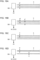
- the medium feeding device includes a container member 1 that accommodates sheet media S, a discharging member 2 that is disposed further than the media S accommodated in the container member 1 in a discharging direction in which the media S are discharged to discharge the media S one by one, a hand-over member 3 that is disposed above the container member 1, sucks the media S (more specifically, a medium S1 located uppermost) accommodated in the container member 1 with air and passes the media S to the discharging member 2, a floating device 4 that is disposed on a side of the media S accommodated in the container member 1, that blows air to an upper area of a side end surface of the media to float the media S while an upper portion of the media S is separated, a detector 5 that detects a separation state of the media floated by the floating device 4, and a controller 6 that controls a medium-feeding operation including a pre-feeding blowing operation BL0 serving as an air blowing operation performed by the floating device 4 before the media S are fed,
- the controller 6 while performing the pre-feeding blowing operation BL0 or the during-feeding blowing operation BL1, the controller 6 performs detection with the detector 5. When a result of the detection fails to satisfy a preset target range, the controller 6 changes a parameter for a medium-feeding operation including at least one of the pre-feeding blowing operation BL0 or the during-feeding blowing operation BL1.
- the medium feeding device of this type is installed in a medium processing device including a processing member not illustrated that performs a predetermined process on the media S, and used as a device that embodies a function of feeding the media S to the processing member.
- examples of the processing member include a device that performs various processing on media such as forming holes in media, cutting media, sorting media, or folding media.
- the container member 1 generally includes a mount that receives the media S thereon, and the mount is usually supported by a hoist mechanism to be movable upward and downward.
- the container member 1 includes side guides and a rear guide.
- Examples of the discharging member 2 include a wide range of members that discharge media, and a typical example of the discharging member 2 includes a pair of discharging rollers or a set of a discharging roller and a discharging belt.
- Any member such as a transport shuttle (a component of a vacuum head) or a transport belt, that sucks media one by one, passes the media to the discharging member 2, and returns to the initial position may be appropriately selected as the hand-over member 3.
- Any member that blows air to the upper area of the accommodated media S from the side of the container member 1 may be selected as the floating device 4.
- any member that images a side end surface of each medium such as a camera or sensor and that detects the separation state of the media S floated by the floating device 4 may be selected as the detector 5 as appropriate.
- the controller 6 controls parameters for the medium-feeding operation including these operations BL0 and BL1 (including an air suction operation performed by the hand-over member 3, and including, in an aspect including an air handling member 8 that blows air to separate an upper medium S1 that has floated toward the side end in a discharging direction of the floating medium S from a medium S located below the upper medium S1, an air blowing operation performed by the air handling member 8, an operation of controlling the position of the uppermost one of the media S1 accommodated in the container member 1, and a control operation for separating media transported in an overlapping manner).
- these operations BL0 and BL1 including an air suction operation performed by the hand-over member 3, and including, in an aspect including an air handling member 8 that blows air to separate an upper medium S1 that has floated toward the side end in a discharging direction of the floating medium S from a medium S located below the upper medium S1, an air blowing operation performed by the air handling member 8, an operation of controlling the position of the uppermost one of the media S1 accommodated in
- the controller 6 identifies the separation state of the media S that float during the pre-feeding blowing operation BL0 or the during-feeding blowing operation BL1, and changes, when the separation state of the media S deviates from a predetermined tolerance range, the parameters for the medium-feeding operation to change the medium-feeding operation conditions to more appropriate conditions.
- the controller 6 performs detection with the detector 5 at a timing when predetermined time elapses from the start of the pre-feeding blowing operation BL0 and during the pre-feeding blowing operation BL0, and changes a parameter for a medium-feeding operation including at least the pre-feeding blowing operation BL0, on condition that a result of the detection fails to satisfy a preset target range.
- the controller 6 on condition that the controller 6 has changed a parameter after performing detection with the detector 5, while performing the pre-feeding blowing operation BL0 after an elapse of predetermined time, the controller 6 preferably performs detection with the detector again on the pre-feeding blowing operation BL0 performed using the previously changed parameter, and on condition that a result of the detection fails to satisfy a preset target range, the controller 6 preferably changes a parameter for the medium-feeding operation at least including the pre-feeding blowing operation BL0.
- the controller 6 that performs the during-feeding blowing operation BL1
- the controller 6 performs detection with the detector 5 at predetermined time intervals, and on condition that a result of the detection fails to satisfy a preset target range, the controller 6 changes a parameter for a medium-feeding operation including at least the during-feeding blowing operation BL1.
- the controller 6 on condition that the controller 6 has changed a parameter after performing detection with the detector 5 while performing the during-feeding blowing operation BL1, the controller 6 preferably performs detection with the detector 5 again on the during-feeding blowing operation BL1 performed using the previously changed parameter after an elapse of predetermined time, and on condition that a result of the detection fails to satisfy a preset target range, the controller 6 preferably changes a parameter for the medium-feeding operation at least including the during-feeding blowing operation BL1.
- the controller 6 performs both the pre-feeding blowing operation BL0 and the during-feeding blowing operation BL1, as illustrated in Fig. 1B , after the media S are feedably accommodated in the container member 1, the controller 6 performs detection with the detector 5 during both the pre-feeding blowing operation BL0 and the during-feeding blowing operation BL1, and on condition that a result of the detection fails to satisfy a preset target range, the controller 6 changes a parameter for a medium-feeding operation including at least one of the pre-feeding blowing operation BL0 or the during-feeding blowing operation BL1.
- the controller 6 to perform detection with the detector 5 first while performing the during-feeding blowing operation BL1, on condition that the controller 6 has changed a parameter after performing detection with the detector 5 during the pre-feeding blowing operation BL0, the controller 6 preferably performs detection with the detector 5 on the during-feeding blowing operation BL1 performed using the parameter changed during the pre-feeding blowing operation BL0.On condition that a result of the detection fails to satisfy a preset target range, the controller 6 preferably changes a parameter for the medium-feeding operation at least including the during-feeding blowing operation BL1.
- the controller 6 To perform second or later detection with the detector 5 while performing the during-feeding blowing operation BL1, on condition that the controller 6 has changed a parameter after performing previous detection with the detector 5 while performing the during-feeding blowing operation BL1, the controller 6 preferably performs detection with the detector 5 again on the during-feeding blowing operation BL1 performed using the previously changed parameter after an elapse of predetermined time. On condition that a result of the detection fails to satisfy a preset target range, the controller 6 preferably changes a parameter for the medium-feeding operation at least including the during-feeding blowing operation BL1.
- the controller 6 preferably performs detection with the detector 5 during the during-feeding blowing operation BL1 and in a period immediately after the discharging member 2 finishes delivering the medium S and before a next medium S adheres to the hand-over member 3.
- the detector 5 performs detection on the floating state of the medium S depending only on the floating device 4. This example is preferable in that the detection is not affected by the medium-feeding operation performed by any device other than the floating device 4.
- Examples of other preferable aspects of the controller 6 include an aspect where, when intermittent operations are intermittently performed during the medium-feeding operation while the during-feeding blowing operation BL1 is performed, a timing when the intermittent operations are not performed is set as a parameter change timing. In other words, in this example, parameters are not changed during the intermittent operations performed intermittently.
- examples of intermittent operations intermittently performed in the medium-feeding operation include an air suction operation performed by the hand-over member 3, and an air blowing operation performed by the air handling member 8.
- parameters are changed at a timing when each intermittent operation is not performed (for example, in a non-operational time period in the medium-feeding operation or a time period between the operation of feeding a first medium S and the operation of feeding a second medium S).
- the during-feeding blowing operation BL1 performed by the floating device 4 is not finished during the medium-feeding operation.
- a parameter change for the floating device 4 may be performed.
- the during-feeding blowing operation BL1 is frequently successively performed without being stopped during the time period between the medium-feeding operations as illustrated in Fig. 1B .
- the parameter change for the floating device 4 is performed after the during-feeding blowing operation is finished as indicated with a virtual line in Fig. 1B .
- the controller 6 does not perform next detection with the detector 5 while performing the during-feeding blowing operation BL1 on condition that a parameter change determined from a previous detection result from the detector 5 is not yet performed.
- the controller 6 does not perform any of detection with the detector 5, parameter change, and detection and parameter change for a predetermined time length after a parameter change while the during-feeding blowing operation BL1 is performed.
- the controller 6 performs detection with the detector 5 after repeatedly performing detection and a parameter change a specific number of times while performing the during-feeding blowing operation BL1, and includes a limiter that limits, on condition that a result of the detection fails to satisfy a target range, the operation of feeding subsequent media S after finishing the operation of feeding the currently fed medium S.
- Examples of the "limiter” in this case include a form of stopping the operation of feeding the media S, a form of notifying that the operation of feeding the media S is out of a target range, and a form of repeating a determining operation until a result of the detection satisfies the target range after the operation of feeding the media S is temporarily stopped.
- the controller 6 performs detection with the detector 5 after repeating, a specific number of times, detection with the detector 5 and a parameter change while performing the pre-feeding blowing operation BL0, and includes a terminator that terminates the pre-feeding blowing operation on condition that a result of the detection fails to satisfy the target range.
- the termination may be notified to a user, or may directly shift to the during-feeding blowing operation, counting on the subsequent step.
- the detector 5 detects the interval between, of all the media S that float in the detection area as a medium separation state, media vertically adjacent to each other to determine whether the interval is within a target range, for example, whether no interval is narrower than a predetermined range.
- the detector 5 detects the thickness of the media S floating in the detection area, to determine whether the thickness is within a target range, for example, whether none of the media has a thickness exceeding a predetermined range.
- the target range is variably set depending on the information of type of media S.
- the information of type of media S includes, for example, a brand, a size, and a basis weight.
- the controller 6 controls an air suction operation performed by the hand-over member 3 in addition to the pre-feeding blowing operation BL0 and the during-feeding blowing operation BL1 performed by the floating device 4, and is capable of changing the parameters to be controlled.
- the controller 6 includes the air handling member 8 that blows air to separate an upper medium S floated by the floating device 4 toward an end of the floating medium S in the discharging direction from a medium located below the upper medium S.
- the controller 6 controls an air blowing operation performed by the air handling member 8 in addition to the pre-feeding blowing operation BL0 and the during-feeding blowing operation BL1 performed by the floating device 4, and is capable of changing the parameters to be controlled.
- Parameters for the medium-feeding operation may be selected as appropriate, and typical examples of parameters include at least one of an airflow rate, a direction of air, an area to which air is blown, an air temperature, an air suction rate, an initial uppermost position of the accommodated media, or a separation position of overlapping media.
- Fig. 2 is a diagram of the entire structure of a medium processing device according to a first exemplary embodiment.
- a medium processing device 10 includes a medium feeding device 11 that feeds sheet media one by one, and a processing unit 20 that serves as a processing member that performs a predetermined process on the media fed from the medium feeding device 11.
- the processing unit 20 includes an image forming unit 21 that forms images on the media.
- the image forming unit 21 employs various image forming methods such as an electrophotographic system or an inkjet printing method.
- the processing unit 20 includes an importing path 22 along which media fed from the medium feeding device 11 are transported to the image forming unit 21, and an exporting path 23 along which media undergoing image formation at the image forming unit 21 are transported out of the processing unit 20.
- the processing unit 20 separately includes a built-in medium feeder 24 below the image forming unit 21. Media from the medium feeder 24 are also fed to the image forming unit 21 through a feed transport path 25.
- Importing rollers 26 are disposed at the entrance of the importing path 22.
- An appropriate number of transporting members are disposed at the importing path 22, the exporting path 23, and the feed transport path 25.
- the medium feeding device 11 includes a housing 12 that accommodates media.
- the housing 12 includes an upper drawer 13 and a lower drawer 14 vertically arranged in two stages to be drawable outward, and a manual feeder 15 disposed at an upper portion of the housing 12 to allow media to be manually fed therethrough.
- the medium feeding device 11 also includes a relay unit 16 on the side of the housing 12 closer to the processing unit 20. The relay unit 16 relays media fed from the upper drawer 13, the lower drawer 14, and the manual feeder 15 to transport the media to the processing unit 20.
- both the upper drawer 13 and the lower drawer 14 accommodate a large number of media and feed the media one by one.
- the relay unit 16 includes a first transport path 17a along which the media fed from the upper drawer 13 are transported, a second transport path 17b along which the media fed from the lower drawer 14 are transported, and a third transport path 17c along which the media fed from the manual feeder 15 are transported.
- An appropriate number of transport rollers 18 are disposed at the first to third transport paths 17a to 17c.
- a merging transport path 17d that is continuous with an outlet port 17e leading to the processing unit 20 is disposed at the exit side of each of the first to third transport paths 17a to 17c.
- Discharge rollers 19 are disposed at the merging transport path 17d.
- the upper drawer 13 and the lower drawer 14 respectively include pulls 13a and 14a to be drawable to the near side.
- the upper drawer 13 and the lower drawer 14 have substantially the same structure.
- the upper drawer 13 is described as an example.
- the upper drawer 13 includes a container 30 serving as a container member that accommodates sheet media, discharging rollers 40 serving as a discharging member disposed further than the media accommodated in the container 30 in a discharging direction in which the media are discharged to discharge the media one by one, a vacuum head 50 disposed above the container 30 to serve as a hand-over member that sucks the media accommodated in the container 30 with air and passes the media to the discharging rollers 40, a floating mechanism 70 that is disposed on a side in a direction crossing the discharging direction in which the media accommodated in the container 30 is discharged, the floating mechanism 70 serving as a floating device that blows air to the side of the media to float the media while separating the upper area of the media, an air handling mechanism 80 disposed further than the media accommodated in the container 30 in a discharging direction in which the media are discharged, the air handling mechanism 80 blowing air to separate an upper medium floated by the
- the container 30 includes a receiving bottom plate 31 that receives media of various sizes, side guides 32 (more specifically, 32a and 32b) disposed on the sides in a width direction crossing the discharging direction of media of various sizes placed on the receiving bottom plate 31 to serve as side guide members that fix and guide the side position of the media, an end guide 33 disposed at a rear side opposite to the side in the discharging direction in which the media loaded on the receiving bottom plate 31 are discharged to serve as a rear guide member that fixes and guides the rear position of the media, and a partitioning plate 34 that defines the position of the media loaded on the receiving bottom plate 31 in the discharging direction in which the media are discharged.
- the container 30 may be designed in accordance with the size of media to be used.
- a normal-size medium is to be mainly used.
- examples of the normal-size medium include media with a length up to 488 mm.
- An example of media with such a size corresponds to media of A3 size or smaller in Japanese Industrial Standards (JIS).
- examples of medium include, in addition to media with a uniform thickness, a medium with an uneven thickness such as an envelope that varies in thickness in the discharging direction.
- the side guides 32 are movable in the width direction of the receiving bottom plate 31, and fixed in a predetermined fixed position.
- the end guide 33 is movable in the discharging direction of the media on the receiving bottom plate 31, and fixed in a predetermined fixed position.
- a separation plate 35 protrudes upward from the upper edge of the partitioning plate 34.
- the separation plate 35 serves as a stopper wall that stops the upper area of a pile of the media located below the medium sucked by the vacuum head 50 with air.
- the receiving bottom plate 31 is supported by a hoist mechanism 90 described below (refer to Figs. 6A and 6B ) to be movable upward and downward.
- the hoist mechanism 90 includes suspension portions 91 disposed at four portions of the receiving bottom plate 31 at both sides in the width direction crossing the medium discharging direction, and four wires 92 to 95 having the far ends coupled to the respective suspension portions 91.
- each of the wires 92 to 95 is wound around one or more guide pulleys 96, a first end of each of the wires 92 to 95 is stuck to coaxially coupled take-up pulleys 97 (97a and 97b in this example), the take-up pulleys 97 are rotated by a driving motor 98 that is rotatable forward and backward, and the wires 92 to 95 are moved by a predetermined amount to raise or lower the receiving bottom plate 31 while keeping the receiving bottom plate 31 in a horizontal position.
- a height sensor 99 sets the surface of one of the media loaded on the receiving bottom plate 31 to a predetermined medium reference height FC (refer to Fig. 7 ).
- the medium reference height FC in this case refers to a position where the uppermost position of the medium is set to be capable of undergoing an air suction operation from the vacuum head 50 on condition that the media S are accommodated in the container 30 in a substantially horizontal position.
- the discharging rollers 40 include a driving roller 41 that drives to rotate, and a driven roller 42 that is driven to rotate following the rotation of the driving roller 41.
- the discharging rollers 40 transport a medium while holding the medium at a contact portion between the driving roller 41 and the driven roller 42.
- a position sensor 45 is disposed downstream from the discharging rollers 40 in the medium discharging direction. This position sensor 45 detects the passage of a medium through a nip area of the discharging rollers 40, and is disposed in a medium passage area. A detection signal from the position sensor 45 notifies the end of the operation of feeding a medium S transported previously, and serves as a trigger of the operation of feeding the subsequent medium S in a successive feeding mode.
- the vacuum head 50 is supported with a guide mechanism 58 (for example, a guide rod) by a head frame 60 fixed to the housing 12 above the container 30 to be movable forward and rearward in the medium discharging direction.
- a guide mechanism 58 for example, a guide rod
- the vacuum head 50 includes a hollow box-shaped head body 51.
- a surface of the head body 51 facing the media accommodated in the container 30 has a large number of vacuum holes 52.
- the vacuum head 50 also includes a skirt portion 51a around the vacuum holes 52 in the head body 51 to keep the medium hermetic while sucking the medium with air.
- a suction mechanism 53 is connected to the head body 51.
- an example used as the suction mechanism 53 has a structure where a suction blower 54 and the head body 51 are connected with a connection duct 55, an open-close valve 56 that opens and shuts the path is disposed at a portion of the connection duct 55, and the open-close valve 56 is opened or shut by a valve motor 57.
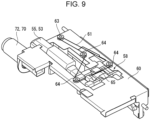
- a forward/rearward moving mechanism 61 that moves the vacuum head 50 forward and rearward is disposed at the head frame 60.
- the forward/rearward moving mechanism 61 fixes a stepping motor 62 to the head frame 60
- a driving pulley 63 is coupled to the stepping motor 62
- a predetermined number of transmission pulleys 64 are disposed at the head frame 60 at appropriate positions
- a wire 65 is wound around the driving pulley 63 and the transmission pulleys 64, and part of the wire 65 is stuck to the vacuum head 50.
- the driving pulley 63 rotates in response to the forward or rearward rotation of the stepping motor 62, the wire 65 moves by a predetermined distance in response, and the vacuum head 50 moves forward or rearward in the medium discharging direction.
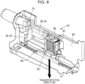
- the floating mechanism 70 includes, for example, hollow box-shaped side guides 32 (32a and 32b).
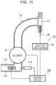
- Each side guide 32 has multiple air outlets 71 at an upper portion facing the side of the media, and has, in the hollow portion, an air duct 72 having one end continuous with the corresponding air outlet 71 and the other end continuous with a blower 73 for blowing air.
- the blower 73 may be installed inside each side guide 32 or disposed outside of the side guide 32.
- An air suction duct 110 in which a heater 111 is installed is connected to the suction port of the blower 73.
- the temperature inside the air suction duct 110 is detected by a temperature sensor 112.
- the information from the temperature sensor 112 is taken into a control device 200, and the heater 111 is controlled to be heated with a control signal from the control device 200.
- medium restrictors 100 are disposed near the air outlets 71 of the side guide 32.
- the medium restrictors 100 in this example are disposed on the side of the media loaded on the receiving bottom plate 31, and protrude to a medium accommodation area to restrict floating excess of media that float while using the floating mechanism 70.
- a shutter mechanism 75 that opens or shuts the air outlets 71 is disposed.
- the shutter mechanism 75 includes a planar shutter 76 covering the air outlet 71 and a shutter driving mechanism 77 that vertically moves the shutter 76 in a reciprocating manner.
- An example used as the shutter driving mechanism 77 in this case includes a driving motor 771 formed from a stepping motor, a driving transmission gear 772 coaxial with a driving shaft of the driving motor 771, a shutter support member 773 that supports a lower portion of the shutter 76, a rack 774 vertically extending at a side edge of the shutter support member 773, and a driving transmission gear train 775 disposed between the rack 774 and the driving transmission gear 772 to engage the rack 774 and the driving transmission gear 772 with each other to transmit the driving force between the rack 774 and the driving transmission gear 772 via the driving transmission gear train 775.
- the driving force from the driving motor 771 driven based on the driving signal from the control device 200 is transmitted to the shutter 76.
- each air outlet 71 is repeatedly opened and shut by the shutter mechanism 75.
- air blown from the air outlets 71 is capable of easily floating the upper portion of the medium S in a fluctuation pattern.
- the shutter mechanism 75 has a slit 78 in a portion of the shutter 76.
- a predetermined inclined portion 78a is disposed to direct the direction of air blows blown from the air outlets 71 to obliquely below.
- this example is preferable in terms of the effect of separating the media S compared to a structure where the direction of all the air blows is substantially uniformly horizontal.
- the inclined portion 78a in the slit 78 in the shutter 76 may be formed from a swingable louver 79 having its angle adjustable. In this case, the pattern of air blows blown from the air outlets 71 is changeable.
- the air handling mechanism 80 includes an air nozzle 81 that blows knife-shaped air to obliquely rearward from below to the end of the medium floated by the floating mechanism 70 in the discharging direction.
- An air guide plate 82 protrudes from a portion of the vacuum head 50 closer to the discharging rollers 40 to change the direction of air blown from the air nozzle 81, and to separate the media by blowing air between the upper medium floated by the floating mechanism 70 and the media located below the upper medium.
- the air nozzle 81 is continuous with an air duct 83, to which an air blowing blower 84 is connected.
- an open-close valve 85 that opens or shuts the flow path is disposed.
- the open-close valve 85 is opened or shut by a valve motor 86.
- the blower 84 is kept driving, air is blown from the air nozzle 81 in a switching manner by opening or shutting the open-close valve 85.
- the flotation detector 120 is disposed at an upper portion of each side guide 32, and is formed from an imaging device such as a camera.
- the number of the flotation detector 120 may be at least one, and may be plural.
- the flotation detector 120 detects the interval between the floating media S.
- a predetermined threshold g0 a level of the medium floating state at which the medium is preferably sucked by the vacuum head 50
- the flotation detector 120 determines the floating state of the media S as being preferable (good).
- the flotation detector 120 determines the floating state of the media S as being poor (no good).
- the flotation detector 120 determines the floating state of the media S as being preferable. Instead, depending on the type of medium (such as a thin paper sheet), a different upper limit threshold may be set to carefully handle the medium considering that the medium S is more likely to float in a poor floating state when the interval exceeds the upper limit threshold.
- the flotation detector 120 detects the interval between the floating media S, but this is not the only possible example.
- the flotation detector 120 may detect the thickness of the floating media S.
- the flotation detector 120 determines that the media S are appropriately separated without being piled together, and thus the flotation detector 120 determines the floating state of the media S as being preferable (good).
- the flotation detector 120 determines that the multiple media S are possibly piled without being separated, and thus the flotation detector 120 determines the floating state of the media S as being poor (no good).
- both the interval of the media S and the thickness of the media S may be detected.
- the present example includes the control device 200 that controls the medium feeding device 11.
- the control device 200 is formed from a microcomputer including various processors.
- processor refers to a processor in a broad sense. Examples of the processor include general processors (for example, a central processing unit or CPU) and dedicated processors (for example, a graphics processing unit or GPU, an application specific integrated circuit or ASIC, a field programmable gate array or FPGA, and a programmable logic device).
- general processors for example, a central processing unit or CPU
- dedicated processors for example, a graphics processing unit or GPU, an application specific integrated circuit or ASIC, a field programmable gate array or FPGA, and a programmable logic device.
- This control device 200 captures, into the processors, various information resulting from, for example, job identification, or signals from various sensors (such as the position sensor 45, the height sensor 99, and the flotation detector 120), executes various programs preinstalled into a memory not illustrated (including an improvement process program of the medium floating state (refer to Fig. 18 to Fig. 20 )), and transmits a predetermined control signal to each control target.
- examples of the control target include the discharging rollers 40, the vacuum head 50 (the suction mechanism 53, and the forward/rearward moving mechanism 61), the floating mechanism 70, the air handling mechanism 80, and the hoist mechanism 90.
- the control device 200 includes a display 210 that displays the processing state of the medium feeding job or a warning indicating an abnormal state in medium feeding.
- the floating mechanism 70 blows floating air from a side of a medium pile to float some upper sheets in the medium pile to the positions to be sucked by the vacuum head 50 with air.
- the open-close valve 56 in the suction mechanism 53 in the vacuum head 50 is opened to cause the vacuum head 50 to form a negative pressure.
- the vacuum head 50 sucks the floating medium S1 located uppermost with air.
- the vacuum head 50 has a recessed portion between the surrounding skirt portion 51a and the surfaces of the vacuum holes 52 in the head body 51.
- the medium S1 is deformed along the recessed portion, and the skirt portion 51a disposed to tightly close the negative pressure area is also raised together with the medium S1.
- the open-close valve 85 in the air handling mechanism 80 is opened, air is applied to the air guide plate 82 located on the side of the vacuum head 50 facing in the discharging direction, to insert separating air between an uppermost medium S1 sucked by the vacuum head 50 with air and second and lower media S located below the uppermost medium S1, and the second and lower media S following the uppermost medium S are dropped down with air.
- the vacuum head 50 holding the uppermost medium S1 moves forward toward the discharging rollers 40, the vacuum head 50 passes the medium S1 to the discharging rollers 40, and then the open-close valve 56 in the vacuum head 50 and the open-close valve 85 in the air handling mechanism 80 are shut.
- the vacuum head 50 is returned to the initial position to be ready for the next medium feeding operation.
- Fig. 17 is a timing chart of each device in the above medium feeding operation process.
- a vacuum-head blower corresponds to "the blower 54" (refer to Figs. 10A and 10B ) in the suction mechanism 53
- an air-handling blower corresponds to “the blower 84” (refer to Figs. 14A to 14C ) in the air handling mechanism 80
- a flotation blower corresponds to "the blower 73" (refer to Fig. 11 ) in the floating mechanism 70.
- a vacuum-valve motor corresponds to the valve motor 57
- an air-handling valve motor corresponds to the valve motor 86
- a vacuum-head motor corresponds to the stepping motor 62 in the forward/rearward moving mechanism 61.
- the vacuum-head blower In this example, “the vacuum-head blower”, “the air-handling blower”, and “the flotation blower” are kept on during the medium feeding job. "The vacuum-valve motor”, “the air-handling valve motor”, and “the vacuum-head motor” repeat on/off control for each sheet medium to repeatedly perform suction and forward/rearward movement with the vacuum head 50 and feeding and stopping feeding of separation air from the air handling mechanism 80.
- the floating mechanism 70 performs the air blowing operation (pre-feeding blowing operation BL0) performed before the media S set in the container 30 are fed, and the air blowing operation (during-feeding blowing operation BL1) performed after the start of feeding the media S set in the container 30 until the end of feeding the media A.
- the floating mechanism 70 floats the media S to suck the media S1 with the vacuum head 50 with air for feeding the media S.
- the floating mechanism 70 performs the above-described pre-feeding blowing operation to separate a pile of the media S set in the container 30 in advance, to preferably float the media S during medium feeding.
- the container 30 raises a pile of the media S loaded on the receiving bottom plate 31 with the hoist mechanism 90 to align the uppermost position of the pile of the media S with the medium reference height FC.
- the loaded media S are sequentially fed.
- the pile of the media S in the container 30 is raised by the hoist mechanism 90, and the media S located below in the loaded pile of the media S arrive at a position where the media S are to be floated by the floating mechanism 70, and float with an air blow from the floating mechanism 70.
- an upper medium group in the loaded pile of the media S located in an upper area, and a lower medium group in the loaded pile located in a lower area differ in the characteristics such as the paper quality attributable to the humidity or dried state.
- the upper medium group and the lower medium group may have a floating state differing from the medium floating state of the previously fed medium S although a predetermined parameter is selected as a floating condition (such as airflow rate of a blow) of the floating mechanism 70.
- a predetermined parameter such as airflow rate of a blow
- keeping the medium feeding operation with the same parameter may lead to an inappropriate separation state (paper jamming or overlapping transport) while the floating mechanism 70 is performing the operation of floating the media S.
- the medium feeding device 11 may be desired to handle various different types of media.
- Different types of media for example, a thin paper sheet and a thick paper sheet vary in the medium floating state.
- the parameters for the medium-feeding operation for example, an airflow rate of the floating mechanism 70, an air suction rate of the vacuum head 50, and an air blow rate of the air handling mechanism 80
- the parameters for the medium-feeding operation may be inappropriate for the thin paper sheet.
- a thin paper sheet may be floated in a poor floating state by the floating mechanism 70, and thus may be, for example, unstably sucked and held by the vacuum head 50.
- a parameter setting may interfere with the medium-feeding operation.
- the present exemplary embodiment employs a control method including determining the medium floating state, and, when the medium floating state is inappropriate, changing the parameters for the medium-feeding operation to improve the medium-feeding operation.
- the process of determining the medium floating state is performed in both the pre-feeding blowing operation BL0 and the during-feeding blowing operation BL1.
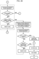
- Fig. 18 to Fig. 20 are flowcharts of the process of improving the medium-feeding operation according to the present exemplary embodiment.
- the process of improving the medium-feeding operation is performed accompanying the pre-feeding blowing operation BL0.
- the pre-feeding blowing operation BL0 may be performed only once, or may be performed multiple times at each predetermined time interval (refer to Fig. 21 ) .
- the floating mechanism 70 (the air outlets 71 and the shutter mechanism 75) performs an air blow as the pre-feeding blowing operation BL0.
- the vacuum head 50 repeatedly performs an operation of sucking air and stopping sucking air multiple times.
- This operation of the vacuum head 50 of sucking air and stopping sucking air is a dummy operation, but is preferable because this operation repeatedly raises or drops upper media, and provides a disturbance to the medium orientation to facilitate separation of the media with a blow.
- the flotation detector 120 performs detection (detects an interval between sheets serving as media in this example) after an elapse of predetermined time, and determines whether a result of the detection falls within a determined target range.
- the flotation detector 120 determines that the floating state of the sheet serving as the medium is poor.
- the flotation detector 120 determines that the floating state of the sheet serving as the medium is preferable.
- the parameter for the medium-feeding operation (corresponding to "the sheet feeding operation") including the pre-feeding blowing operation BL0, or in this example, a parameter PM1 (refer to Fig. 7 ) for the air blowing operation performed by the floating mechanism 70 is changed.
- an air blow rate from the air outlets 71 selected as an example of the parameter PM1 is changed to be increased because the floating state is determined as being poor due to a narrow interval between the sheets serving as the media.
- the parameter PM1 may be selected as appropriate from any conditions that affect the operation of floating the media with the floating mechanism 70, for example, the air temperature, an air blowing direction, or an air blowing pattern.
- the heating condition of the heater 111 may be changed.
- the pattern or time of opening or shutting the shutter 76, or the inclination direction of the slit 78 in the shutter 76 may be changed.
- the parameter PM1 may be changed at a timing when the pre-feeding blowing operation BL0 is not performed, and the changed parameter PM1 is applied to the next pre-feeding blowing operation BL0.
- the changed parameter PM1 is applied to the during-feeding blowing operation BL1 performed first in the medium-feeding operation.
- the operation mode of the medium feeding device 11 is selected.
- the display 210 (refer to Fig. 4 ) displays a warning.
- a process of improving the medium-feeding operation is performed accompanying the during-feeding blowing operation BL1.
- the during-feeding blowing operation BL1 is performed every time when the medium-feeding operation is performed (refer to Fig. 21 ).
- Fig. 19 when an instruction to start feeding sheets serving as media is received, the floating mechanism 70 starts blowing air, and the shutter mechanism 75 starts the opening and shutting operation.
- the vacuum head 50 sucks the sheets serving as media
- the air handling mechanism 80 starts blowing air
- the vacuum head 50 transports the sucked sheets serving as media toward the discharging rollers 40.
- the flotation detector 120 measures the interval between the sheets serving as media to determine whether the interval is within the determined target range.
- the parameter PM1 is changed in this example on condition that the parameter is out of the target range (refer to Fig. 21 ).
- the during-feeding blowing operation BL1 is not finished during the sheet feeding operation. After an elapse of predetermined time after the feeding operation is finished, the during-feeding blowing operation BL1 is temporarily finished. In this manner, the shutter mechanism 75 and the blower 54 in the floating mechanism 70 are controlled to be turned on or off for each sheet feeding job.
- the floating mechanism 70 when, for example, a job of feeding sequential sheets (n sheets) is specified, the floating mechanism 70 successively performs the during-feeding blowing operation BL1 also during intermittent sheet feeding operations (an operation of feeding a first sheet, an operation of feeding a second sheet, ..., and an operation of feeding an n-th sheet).
- the job of feeding successive sheets is controlled in such a manner that a time period after one sheet feeding operation is finished and before the floating mechanism 70 is turned off (after-blow time) is set long, and when the next sheet feeding operation is started before the floating mechanism 70 is turned off, turning off the air blowing operation of the floating mechanism 70 is cancelled.
- the floating mechanism 70 successively performs the during-feeding blowing operation BL1
- the floating mechanism 70 stably performs the operation of floating the media during the job of feeding successive sheets.
- the floating mechanism 70 changes the parameter PM1 when the floating mechanism 70 is not performing the during-feeding blowing operation BL1.
- the floating mechanism 70 may naturally change the parameter PM1 in the time period between the feeding operations.
- the changed parameter is used in the next during-feeding blowing operation BL1.
- the process returns to C in Fig. 19 , and the medium-feeding operation is performed until the number of sheets fed arrives at the prescribed number of sheets.
- the flotation detector 120 measures the interval between the sheets serving as media, and determines whether the interval is within the determined target range. When the interval is within the determined target range, the flotation detector 120 restarts the sheet feeding operation, and then, as illustrated in Fig. 19 , performs the sheet feeding operation until the number of sheets fed arrives at the prescribed number of sheets.
- the parameter change is performed on condition that the number of times the parameter is changed has not arrived at the prescribed number of times (N times).
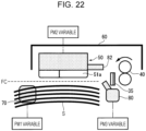
- Fig. 22 illustrates a related portion of a medium feeding device according to the second exemplary embodiment.
- the medium feeding device 11 has a basic structure substantially the same as that of the first exemplary embodiment, but differs from the first exemplary embodiment in parameters for the medium-feeding operation that are to be changed when a result of the detection of the flotation detector 120 deviates from the predetermined target range.
- a parameter (PM2) for the air suction operation performed by the vacuum head 50 and a parameter (PM3) for the air blowing operation performed by the air handling mechanism 80 are to be changed.
- the air suction operation performed by the vacuum head 50 and the air blowing operation performed by the air handling mechanism 80 are intermittently performed for each medium-feeding operation (corresponding to "the sheet feeding operation" in Fig. 21 ).
- the parameters PM2 and PM3 for these operations are changed when the medium-feeding operation is not intermittently performed (for example, in a time period during the medium-feeding operation not intermittently performed or in the time period between the medium-feeding operations).
- the parameter PM1 of the floating mechanism 70 is similar to that in the first exemplary embodiment.
- Examples of the parameter PM2 of the vacuum head 50 include an air suction rate of the vacuum head 50.
- the degree of opening of the open-close valve 56 in the suction mechanism 53 in the vacuum head 50 is adjustable successively or stepwise, and the degree of opening of the open-close valve 56 is changeable with the valve motor 57.
- the air suction rate may be increased to enhance the suction force of the vacuum head 50 to suck the medium.
- the open-close valve 56 may be opened or shut by being turned on or off to change the number of rotations of the blower 84.
- parameter PM2 include the time length for which and the start timing at which the vacuum head 50 performs air suction.
- Examples of the parameter PM3 of the air handling mechanism 80 include an air blow rate from the air nozzle 81, an air blow area, and an air blowing direction.
- the air blow rate" from the air nozzle 81 is changeable by changing, with the valve motor 86, the degree of opening of the open-close valve 85 in the air handling mechanism 80 that is adjustable successively or stepwise.
- the open-close valve 85 may be opened or shut by being turned on or off to change the number of rotations of the blower 84.
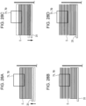
- the air blow area may be changed by arranging one or more sets of multiple (three in this example) air handling mechanisms 80 (more specifically, 80a to 80c) to orient the respective blow areas toward a blown area Sw of the medium S.
- the air blowing direction or an air blowing direction ⁇ (an angle with respect to the horizon) from the air nozzle 81 is changeable by swingably disposing a louver 87 for restricting the air direction in, for example, the air nozzle 81, and changing the direction of the louver 87 that is drivable by an actuator 88 such as a solenoid.
- FIG. 25A, 25D, and 25E another example for changing "the air blow direction" is to connect, to the air duct 83, two air nozzles 81 (more specifically, 81a and 81b) that blow air in different directions, disposing a switching valve 89 at a connection portion of the air duct 83 continuous to the two air nozzles 81 (81a and 81b), switching this switching valve 89 to be securely connected to either one of the air nozzles 81 (81a and 81b) to select the air nozzle 81 (81a or 81b) in a switching manner.
- three parameters PM1 to PM3 are changed, but this is not the only possible example.
- two parameters PM1 and PM2, two parameters PM1 and PM3, or two parameters PM2 and PM3 may be changed, or, only the parameter PM2 or PM3 may be changed instead of the parameter PM1.
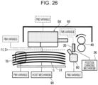
- Fig. 26 illustrates a related portion of a medium feeding device according to a third exemplary embodiment.
- the medium feeding device 11 has substantially the same basic structure as the first and second exemplary embodiments, but differs from the first and second exemplary embodiments in the parameters for the medium-feeding operation to be changed when a result of the detection of the flotation detector 120 deviates from the predetermined target range.
- a parameter (PM4, corresponding to the medium reference height FC) for the height position of the pile of the media S loaded on the container 30, and a parameter (PM5) for the upper end position of the separation plate 35 are selected.
- the height adjustment of the pile of the media S loaded on the container 30 and the adjustment of the vertical position of the separation plate 35 are intermittently performed for each medium-feeding operation (corresponding to "the sheet feeding operation" in Fig. 21 ).
- the parameters PM4 and PM5 for these operations are changed at a timing when the medium-feeding operation is not intermittently performed (for example, in the time period during the medium-feeding operation not intermittently performed or in the time period between the medium-feeding operations).
- the medium feeding device 11 appropriately raises or lowers the receiving bottom plate 31 with the hoist mechanism 90 to change the uppermost position of the pile of the media S loaded on the receiving bottom plate 31, that is, the height position of the pile of the media S.
- the height position of the pile of the media S is normally adjusted to correspond to the medium reference height FC.
- the height position of the pile of the media S facing the air outlets 71 of the floating mechanism 70 is changed, the number of media accommodated in the area facing the air outlets 71 is changed, and thus the number of media separated by the air blown from the air outlets 71 is changed.
- the floating state of the media S is changed.
- the flotation detector 120 performs detection (measures the interval between the sheets serving as media), and determines whether a result of the detection is within a predetermined target range.
- the target range indicates the range between the upper-limit threshold and the lower-limit threshold.
- the position of the receiving bottom plate 31 may be raised to raise the height position of the pile of the media to change the parameter PM4.
- the sheets serving as media when the interval between the sheets serving as media is smaller than the target range, the sheets may be transported while overlapping each other.
- the position of the receiving bottom plate 31 may be lowered to lower the height position of the pile of the media to change the parameter PM4.
- decreasing the number of sheets facing the air outlets 71 allows reduction of the number of sheets receiving an air blow, and reduction of the number of sheets to be floated and separated.
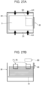
- the medium feeding device 11 includes the separation plate 35 in front of a contact area (nip area) of the discharging rollers 40.
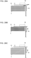
- the separation plate 35 prevents overlapping transport, or a phenomenon where a sheet S1 transported while being sucked and held by the vacuum head 50 and a sheet S2 located below the sheet S1 are transported together.
- the separation plate 35 is supported by a position changing mechanism 36.
- This position changing mechanism 36 is formed from, for example, an actuator that moves in the vertical direction to change the vertical position of the separation plate 35.
- the flotation detector 120 performs detection (measures the interval between the sheets serving as media), and determines whether a result of the detection falls within the predetermined target range.
- the target range indicates the range between the upper-limit threshold and the lower-limit threshold.
- the upper end position of the separation plate 35 may be raised to change the parameter PM5 as illustrated in Fig. 29B .
- the upper end position of the separation plate 35 may be lowered to change the parameter PM5 as illustrated in Fig. 29C .
- the lower sheet S2 is more easily blocked.
- the sheet S1 that is to be provided may be allowed to flow more easily to less easily cause paper jamming.
- the five parameters PM1 to PM5 are changed in the parameter change, but this is not the only possible example. Two, three, or four parameters including the parameter PM4 or PM5 may be changed. Instead, only the parameter PM4 or PM5 may be changed.
Landscapes
- Engineering & Computer Science (AREA)
- Mechanical Engineering (AREA)
- Sheets, Magazines, And Separation Thereof (AREA)
Abstract
Description
- The present disclosure relates to a medium feeding device that feeds media such as sheets one by one.
- For example, a device described in
Japanese Unexamined Patent Application Publication No. 2020-152561 Fig. 7 ) is known as this type of medium feeding device. -
Japanese Unexamined Patent Application Publication No. 2020-152561 Fig. 7 ) describes a sheet feeding device including a sheet feeding belt disposed above sheets set on a set board and having a suction hole, a suction device that sucks air from the sheet feeding belt to produce floating air to suck the set sheets, a discharging mechanism that discharges sheets by rotating the sheet feeding belt, an interval measuring unit that measures an interval between the sheets while the suction device sucks the sheets, and a controller that identifies the interval between the sheets based on an output from the interval measuring unit, and adjusts the airflow rate of the floating air based on the identified interval between the sheets. - Accordingly, it is an object of the present disclosure to further reduce, while performing a method of feeding media by floating and sucking the media one by one, sheet feeding failures by determining an operation of floating each medium than when feeding media with constantly unchanged parameters.
- According to a first aspect of the present disclosure, there is provided a medium feeding device including a container member that accommodates sheet media, a discharging member located further than the media accommodated in the container member in a discharging direction in which the media are discharged to discharge the media one by one, a hand-over member disposed above the container member to suck the media accommodated in the container member with air and pass the media to the discharging member, a floating device disposed on a side of the media accommodated in the container member to blow air to an upper area of a side end surface of the media to float the media while an upper portion of the media is separated, a detector that detects a separation state of the medium floated by the floating device, and a controller that controls a medium-feeding operation including a pre-feeding blowing operation and a during-feeding blowing operation, the pre-feeding blowing operation serving as an air blowing operation performed by the floating device before the medium is fed, and the during-feeding blowing operation serving as an air blowing operation performed by the floating device from a start of feeding the medium to an end of feeding the medium, wherein while performing the pre-feeding blowing operation or the during-feeding blowing operation, the controller performs detection with the detector. On condition that a result of the detection fails to satisfy a preset target range, the controller changes a parameter for the medium-feeding operation including at least one of the pre-feeding blowing operation or the during-feeding blowing operation.
- According to a second aspect of the present disclosure, there is a medium feeding device having the first aspect, wherein after the media are feedably accommodated in the container member and at a time point when a predetermined time elapses from a start of the pre-feeding blowing operation while the pre-feeding blowing operation is performed, the controller performs detection with the detector, and on condition that a result of the detection fails to satisfy the preset target range, the controller changes a parameter for the medium-feeding operation including at least the pre-feeding blowing operation.
- According to a third aspect of the present disclosure, there is a medium feeding device having the second aspect wherein, on condition that the controller has changed the parameter after performing detection with the detector while the pre-feeding blowing operation is performed, the controller performs detection with the detector again on the pre-feeding blowing operation performed using the parameter previously changed while the pre-feeding blowing operation is performed after an elapse of predetermined time, and on condition that a result of the detection fails to satisfy the preset target range, the controller changes a parameter for the medium-feeding operation including at least the pre-feeding blowing operation.
- According to a fourth aspect of the present disclosure, there is a medium feeding device having the first aspect wherein after the media are feedably accommodated in the container member and while the during-feeding blowing operation is performed, the controller performs detection with the detector at a predetermined time interval, and on condition that a result of the detection fails to satisfy the preset target range, the controller changes a parameter for the medium-feeding operation including at least the during-feeding blowing operation.
- According to a fifth aspect of the present disclosure, there is a medium feeding device having the fourth aspect wherein, on condition that the controller has changed the parameter after performing detection with the detector while the during-feeding blowing operation is performed, the controller performs detection with the detector again on the during-feeding blowing operation performed using the parameter previously changed after an elapse of predetermined time, and on condition that a result of the detection fails to satisfy the preset target range, the controller changes a parameter for the medium-feeding operation including at least the during-feeding blowing operation.
- According to a sixth aspect of the present disclosure, there is a medium feeding device having the first aspect wherein after the media are feedably accommodated in the container member and while the pre-feeding blowing operation and the during-feeding blowing operation are both performed, the controller performs detection with the detector, and on condition that a result of the detection fails to satisfy the preset target range, the controller changes a parameter for the medium-feeding operation including at least the pre-feeding blowing operation or the during-feeding blowing operation.
- According to a seventh aspect of the present disclosure, there is a medium feeding device having the sixth aspect wherein, to perform detection with the detector first during a period when the during-feeding blowing operation is performed, on condition that the controller has changed the parameter after performing detection with the detector while the pre-feeding blowing operation is performed, the controller performs detection with the detector on the during-feeding blowing operation performed using the parameter changed in the pre-feeding blowing operation, and on condition that a result of the detection fails to satisfy the preset target range, the controller changes a parameter for the medium-feeding operation including at least the during-feeding blowing operation, and wherein to perform detection with the detector for second and subsequent times during a period when the during-feeding blowing operation is performed, on condition that the controller has changed the parameter after performing previous detection with the detector while the during-feeding blowing operation is performed, the controller performs detection with the detector again on the during-feeding blowing operation performed using the parameter previously changed after an elapse of predetermined time, and operation on condition that a result of the detection fails to satisfy the preset target range, the controller changes a parameter for the medium-feeding operation including at least the during-feeding blowing operation.
- According to an eighth aspect of the present disclosure, there is a medium feeding device having the first aspect wherein the controller performs detection with the detector while the during-feeding blowing operation is performed immediately after the discharging member finishes an operation of transporting one of the media and before the hand-over member sucks a next one of the media.
- According to a ninth aspect of the present disclosure, there is a medium feeding device having the first aspect wherein the controller determines, as a timing to change the parameter, a timing when intermittent operations performed intermittently during the medium-feeding operation are not performed while the during-feeding blowing operation is performed.
- According to a tenth aspect of the present disclosure, there is a medium feeding device having the ninth aspect wherein the controller does not perform next detection with the detector on condition that the parameter determined to be changed based on a result of previous detection from the detector is left unchanged while the during-feeding blowing operation is performed.
- According to an eleventh aspect of the present disclosure, there is a medium feeding device having the ninth aspect wherein the controller does not perform any of detection with the detector, a change of the parameter, and the detection and the change in a predetermined time period after the change of the parameter while the during-feeding blowing operation is performed.
- According to a twelfth aspect of the present disclosure, there is a medium feeding device having the first aspect wherein after repeating detection with the detector and a change of the parameter a predetermined number of times while the during-feeding blowing operation is performed, the controller performs detection with the detector, and the controller includes a limiter that limits, on condition that a result of the detection fails to satisfy the target range, a medium feeding operation to be performed after the operation of feeding a medium that is being fed is finished.
- According to a thirteenth aspect of the present disclosure, there is a medium feeding device having the first aspect wherein after repeating detection with the detector and a change of the parameter a predetermined number of times while the pre-feeding blowing operation is performed, the controller performs detection with the detector, and the controller includes a terminator that terminates, on condition that a result of the detection fails to satisfy the target range, the pre-feeding blowing operation.
- A fourteenth aspect of the present disclosure is a medium feeding device having the first aspect including an air handling member that blows separation air to an upper medium and a medium located below the upper medium, the upper medium being floated by the floating device toward an end of the floated medium in a direction in which the medium is discharged, wherein the controller controls, as a control target, an air blowing operation of the air handling member in addition to the pre-feeding blowing operation and the during-feeding blowing operation performed by the floating device, and is capable of changing a parameter of the control target.
- A fifteenth aspect of the present disclosure is a medium feeding device having the first aspect wherein the parameter for the medium-feeding operation includes at least one of an airflow rate, a direction of air, an area to which air is blown, an air temperature, an air suction rate, an initial uppermost position of the accommodated media, or a separation position of overlapping media.
- The first aspect of the present disclosure is capable of further reducing failures in feeding media when the media are floated and sucked one by one to be fed, while the operation of floating the media is determined unlike in the case where the media are kept being fed at the same parameter.
- The second aspect of the present disclosure is capable of preventing and reducing failures in feeding media during a pre-feeding blowing operation performed with a floating device while determining a floating operation of the media.
- The third aspect of the present disclosure is capable of determining the floating operation of the media multiple times during the pre-feeding blowing operation performed with the floating device, and is capable of further reducing failures in feeding media than when determining the floating operation once.
- The fourth aspect of the present disclosure is capable of reducing failures in feeding media during the during-feeding blowing operation performed with the floating device while determining the floating operation of the media.
- The fifth aspect of the present disclosure is capable of determining the floating operation of the media multiple times during the during-feeding blowing operation performed with the floating device, and thus further reducing failures in feeding media.
- The sixth aspect of the present disclosure is capable of determining the floating operation of the media in the pre-feeding blowing operation and the during-feeding blowing operation performed with the floating device, and is capable of further reducing failures in feeding media than when the floating operation of the media is not determined in the pre-feeding blowing operation.
- The seventh aspect of the present disclosure is capable of effectively using check information of the floating operation of the media performed in the pre-feeding blowing operation during the during-feeding blowing operation performed with the floating device, and is capable of correcting the floating operation of the media as appropriate.
- The eighth aspect of the present disclosure is capable of detecting a separation state of media floated by only the during-feeding blowing operation with the floating device without being affected by the medium feeding operation performed with the floating device.
- The ninth aspect of the present disclosure is capable of preventing a change of the parameter during the intermittent operations performed intermittently during the during-feeding blowing operation with the floating device.
- The tenth aspect of the present disclosure is capable of preventing a useless operation check by preceding a previous determination and restricting the following operation check when a parameter change performed by the controller takes time.
- The eleventh aspect of the present disclosure is capable of stabilizing the effect of a parameter change without a useless operation check when the controller performs the parameter change.
- The twelfth aspect of the present disclosure is capable of preventing a failure in feeding media by restricting the operation of feeding media when detection on the during-feeding blowing operation repeated a specific number of times fails to satisfy the target range while the during-feeding blowing operation is performed.
- The thirteenth aspect of the present disclosure is capable of proceeding to the operation of feeding media by forcibly terminating the pre-feeding blowing operation when detection on the pre-feeding blowing operation repeated a specific number of times fails to satisfy the target range while the pre-feeding blowing operation is performed.
- The fourteenth aspect of the present disclosure is capable of changing the parameter for the medium feeding operation performed with the floating device and an air handling member.
- The fifteenth aspect of the present disclosure is capable of appropriately selecting the parameter for the medium feeding operation.
- Exemplary embodiments of the present disclosure will be described in detail based on the following figures, wherein:
-
Fig. 1A is a rough schematic diagram of a medium feeding device according to an exemplary embodiment of the present disclosure, andFig. 1B is a rough timing chart of a control operation performed by a controller; -
Fig. 2 is a diagram of the entire structure of a medium processing device according to a first exemplary embodiment; -
Fig. 3 is diagram of a medium feeding device included in the medium processing device according to the first exemplary embodiment; -
Fig. 4 is a diagram of a drive control system in the medium feeding device according to the first exemplary embodiment; -
Fig. 5 is a perspective view of a medium container in the medium feeding device according to the first exemplary embodiment; -
Fig. 6A is a diagram of a hoist mechanism illustrated inFig. 4 , andFig. 6B is a perspective view of a related portion of the hoist mechanism illustrated inFig. 6A ; -
Fig. 7 is a diagram of a related portion of the medium feeding device according to the first exemplary embodiment; -
Fig. 8 is a detailed diagram of a vacuum head serving as a hand-over member according to the first exemplary embodiment; -
Fig. 9 is a diagram of a forward/rearward moving mechanism of the vacuum head viewed in a direction IX inFig. 8 ; -
Figs. 10A and 10B are diagrams of a suction mechanism in the vacuum head, whereFig. 10A illustrates a state where the suction mechanism performs sucking, andFig. 10B illustrates a state where the suction mechanism stops sucking; -
Fig. 11 is a diagram of a floating mechanism illustrated inFig. 4 ; -
Figs. 12A and 12B are diagrams of a shutter mechanism included in the floating mechanism, whereFig. 12A is a state where an air outlet of the shutter mechanism is shut, andFig. 12B is a state where the air outlet of the shutter mechanism is open; -
Figs. 13A, 13B, and 13C are diagrams of the shutter mechanism inFigs. 12A and 12B , whereFig. 13A is a diagram illustrating a case where the direction in which air from the air outlet is blown is partially changed,Fig. 13B is a cross-sectional view taken along line XIIIB-XIIIB inFig. 13A, and Fig. 13C is a diagram illustrating a case where a pattern in which air from the air outlet is blown is used as a parameter to be changed; -
Fig. 14A is a diagram of an air handling mechanism illustrated inFig. 7 ,Fig. 14B is a diagram of a state where air is blown when viewed in a direction of arrow XIVB inFig. 14A, and Fig. 14C is a diagram of a state where air is not blown. -
Fig. 15A is a diagram of a detection example where the interval at which the media are floated by the flotation detector is normal,Fig. 15B is a diagram of a detection example where the interval at which the media are floated by the flotation detector is abnormal,Fig. 15C is a diagram of a detection example where the medium detected by the flotation detector has a normal thickness, andFig. 15D is a diagram of a detection example where the medium detected by the flotation detector has an abnormal thickness; -
Figs. 16A to 16E are diagrams of a basic medium feeding operation process performed by the medium feeding device according to the first exemplary embodiment; -
Fig. 17 is a timing chart of a basic medium feeding operation performed by the medium feeding device illustrated inFigs. 16A to 16E ; -
Fig. 18 is a flowchart (1) of a control operation performed by the medium feeding device according to the first exemplary embodiment; -
Fig. 19 is a flowchart (2) following the flowchart (1) illustrated inFig. 18 ; -
Fig. 20 is a flowchart (3) following the flowchart (2) illustrated inFig. 19 ; -
Fig. 21 is a timing chart of a control operation performed in the pre-feeding blowing operation and the during-feeding blowing operation by the floating mechanism; -
Fig. 22 is a diagram of a related portion of a medium feeding device according to a second exemplary embodiment; -
Fig. 23 is a diagram of an example where the parameter of the vacuum head according to the second exemplary embodiment is variable; -
Fig. 24A is a diagram of an example where the air blow rate serving as a parameter of an air handling mechanism according to a second exemplary embodiment is variable, andFig. 24B is a diagram of an example where the air blow area serving as a parameter of the air handling mechanism is variable; -
Fig. 25A is a diagram of an example where the air blowing direction serving as a parameter of the air handling mechanism according to the second exemplary embodiment is variable,Fig. 25B is a diagram of a structure example 1 where the air blowing direction illustrated inFig. 25A is variable,Fig. 25C is a diagram illustrating an operation performed to make the air blowing direction variable in the structure example 1 illustrated inFig. 25B, Fig. 25D is a diagram of a structure example 2 where the air blowing direction illustrated inFig. 25A is variable, andFig. 25E is a diagram illustrating an operation performed to make the air blowing direction variable in the structure example 2 illustrated inFig. 25D ; -
Fig. 26 is a diagram of a related portion of a medium feeding device according to a third exemplary embodiment; -
Fig. 27A is a schematic plan view of a layout around a container, andFig. 27B is a front view of the layout; -
Figs. 28A to 28D are diagrams illustrating a change of a parameter PM4 (medium reference height),Fig. 28A is a diagram illustrating the behavior exhibited to raise the medium reference height,Fig. 28B is a diagram illustrating the operation when the medium reference height is raised,Fig. 28C is a diagram illustrating the behavior exhibited to lower the medium reference height, andFig. 28D is a diagram illustrating the operation when the medium reference height is lowered; and -
Figs. 29A to 29C are diagrams illustrating a change of a parameter PM5 (a vertical position of a separation plate), whereFig. 29A is a diagram of a basic operation of the separation plate,Fig. 29B is a diagram of the operation when the position of the separation plate is raised, andFig. 29C is a diagram of the operation when the position of the separation plate is lowered. -
Fig. 1A is a rough diagram of a medium feeding device according to an exemplary embodiment of the present disclosure. - In
Fig. 1A , the medium feeding device includes acontainer member 1 that accommodates sheet media S, a dischargingmember 2 that is disposed further than the media S accommodated in thecontainer member 1 in a discharging direction in which the media S are discharged to discharge the media S one by one, a hand-over member 3 that is disposed above thecontainer member 1, sucks the media S (more specifically, a medium S1 located uppermost) accommodated in thecontainer member 1 with air and passes the media S to the dischargingmember 2, a floating device 4 that is disposed on a side of the media S accommodated in thecontainer member 1, that blows air to an upper area of a side end surface of the media to float the media S while an upper portion of the media S is separated, adetector 5 that detects a separation state of the media floated by the floating device 4, and acontroller 6 that controls a medium-feeding operation including a pre-feeding blowing operation BL0 serving as an air blowing operation performed by the floating device 4 before the media S are fed, and a during-feeding blowing operation BL1 serving as an air blowing operation performed by the floating device 4 from a start of feeding the media S to an end of feeding the media S. As illustrated inFig. 1B , while performing the pre-feeding blowing operation BL0 or the during-feeding blowing operation BL1, thecontroller 6 performs detection with thedetector 5. When a result of the detection fails to satisfy a preset target range, thecontroller 6 changes a parameter for a medium-feeding operation including at least one of the pre-feeding blowing operation BL0 or the during-feeding blowing operation BL1. - The medium feeding device of this type is installed in a medium processing device including a processing member not illustrated that performs a predetermined process on the media S, and used as a device that embodies a function of feeding the media S to the processing member.
- In this case, in addition to an image forming member that forms images on the media S, examples of the processing member include a device that performs various processing on media such as forming holes in media, cutting media, sorting media, or folding media.
- In such as a technical member, the
container member 1 generally includes a mount that receives the media S thereon, and the mount is usually supported by a hoist mechanism to be movable upward and downward. In an aspect of accommodating the media S of various different sizes, thecontainer member 1 includes side guides and a rear guide. - Examples of the discharging
member 2 include a wide range of members that discharge media, and a typical example of the dischargingmember 2 includes a pair of discharging rollers or a set of a discharging roller and a discharging belt. - Any member, such as a transport shuttle (a component of a vacuum head) or a transport belt, that sucks media one by one, passes the media to the discharging
member 2, and returns to the initial position may be appropriately selected as the hand-over member 3. - Any member that blows air to the upper area of the accommodated media S from the side of the container member 1 (including from the front or rear side in a medium discharging direction besides from the side in a width direction crossing the medium discharging direction) may be selected as the floating device 4.
- Any member that images a side end surface of each medium such as a camera or sensor and that detects the separation state of the media S floated by the floating device 4 may be selected as the
detector 5 as appropriate. - In addition, instead of an aspect of controlling the pre-feeding blowing operation BL0 before medium feeding and the during-feeding blowing operation BL1 during medium feeding, the
controller 6 controls parameters for the medium-feeding operation including these operations BL0 and BL1 (including an air suction operation performed by the hand-over member 3, and including, in an aspect including anair handling member 8 that blows air to separate an upper medium S1 that has floated toward the side end in a discharging direction of the floating medium S from a medium S located below the upper medium S1, an air blowing operation performed by theair handling member 8, an operation of controlling the position of the uppermost one of the media S1 accommodated in thecontainer member 1, and a control operation for separating media transported in an overlapping manner). Thecontroller 6 identifies the separation state of the media S that float during the pre-feeding blowing operation BL0 or the during-feeding blowing operation BL1, and changes, when the separation state of the media S deviates from a predetermined tolerance range, the parameters for the medium-feeding operation to change the medium-feeding operation conditions to more appropriate conditions. - Subsequently, a typical aspect or a preferable aspect of a medium feeding device according to an exemplary embodiment will be described.
- First, as a typical aspect of the
controller 6 that performs the pre-feeding blowing operation BL0, as illustrated inFig. 1B , after the media S are feedably accommodated in the container member 1 (corresponding to "medium setting ST" in the drawing), thecontroller 6 performs detection with thedetector 5 at a timing when predetermined time elapses from the start of the pre-feeding blowing operation BL0 and during the pre-feeding blowing operation BL0, and changes a parameter for a medium-feeding operation including at least the pre-feeding blowing operation BL0, on condition that a result of the detection fails to satisfy a preset target range. - In this example, on condition that the
controller 6 has changed a parameter after performing detection with thedetector 5, while performing the pre-feeding blowing operation BL0 after an elapse of predetermined time, thecontroller 6 preferably performs detection with the detector again on the pre-feeding blowing operation BL0 performed using the previously changed parameter, and on condition that a result of the detection fails to satisfy a preset target range, thecontroller 6 preferably changes a parameter for the medium-feeding operation at least including the pre-feeding blowing operation BL0. - As a typical aspect of the
controller 6 that performs the during-feeding blowing operation BL1, as illustrated inFig. 1B , after the media S are feedably accommodated in thecontainer member 1 and during the during-feeding blowing operation BL1, thecontroller 6 performs detection with thedetector 5 at predetermined time intervals, and on condition that a result of the detection fails to satisfy a preset target range, thecontroller 6 changes a parameter for a medium-feeding operation including at least the during-feeding blowing operation BL1. - In this example, on condition that the
controller 6 has changed a parameter after performing detection with thedetector 5 while performing the during-feeding blowing operation BL1, thecontroller 6 preferably performs detection with thedetector 5 again on the during-feeding blowing operation BL1 performed using the previously changed parameter after an elapse of predetermined time, and on condition that a result of the detection fails to satisfy a preset target range, thecontroller 6 preferably changes a parameter for the medium-feeding operation at least including the during-feeding blowing operation BL1. - In addition, in a typical aspect of the
controller 6 that performs both the pre-feeding blowing operation BL0 and the during-feeding blowing operation BL1, as illustrated inFig. 1B , after the media S are feedably accommodated in thecontainer member 1, thecontroller 6 performs detection with thedetector 5 during both the pre-feeding blowing operation BL0 and the during-feeding blowing operation BL1, and on condition that a result of the detection fails to satisfy a preset target range, thecontroller 6 changes a parameter for a medium-feeding operation including at least one of the pre-feeding blowing operation BL0 or the during-feeding blowing operation BL1. - In this example, to perform detection with the
detector 5 first while performing the during-feeding blowing operation BL1, on condition that thecontroller 6 has changed a parameter after performing detection with thedetector 5 during the pre-feeding blowing operation BL0, thecontroller 6 preferably performs detection with thedetector 5 on the during-feeding blowing operation BL1 performed using the parameter changed during the pre-feeding blowing operation BL0.On condition that a result of the detection fails to satisfy a preset target range, thecontroller 6 preferably changes a parameter for the medium-feeding operation at least including the during-feeding blowing operation BL1. To perform second or later detection with thedetector 5 while performing the during-feeding blowing operation BL1, on condition that thecontroller 6 has changed a parameter after performing previous detection with thedetector 5 while performing the during-feeding blowing operation BL1, thecontroller 6 preferably performs detection with thedetector 5 again on the during-feeding blowing operation BL1 performed using the previously changed parameter after an elapse of predetermined time. On condition that a result of the detection fails to satisfy a preset target range, thecontroller 6 preferably changes a parameter for the medium-feeding operation at least including the during-feeding blowing operation BL1. - In a preferable aspect of the
controller 6, thecontroller 6 preferably performs detection with thedetector 5 during the during-feeding blowing operation BL1 and in a period immediately after the dischargingmember 2 finishes delivering the medium S and before a next medium S adheres to the hand-over member 3. In this example, thedetector 5 performs detection on the floating state of the medium S depending only on the floating device 4. This example is preferable in that the detection is not affected by the medium-feeding operation performed by any device other than the floating device 4. - Examples of other preferable aspects of the
controller 6 include an aspect where, when intermittent operations are intermittently performed during the medium-feeding operation while the during-feeding blowing operation BL1 is performed, a timing when the intermittent operations are not performed is set as a parameter change timing. In other words, in this example, parameters are not changed during the intermittent operations performed intermittently. - For example, as illustrated in
Fig. 1B , assume an example case where detection is performed with thedetector 5 during an operation of feeding a first medium S. In this case, examples of intermittent operations intermittently performed in the medium-feeding operation include an air suction operation performed by the hand-over member 3, and an air blowing operation performed by theair handling member 8. For these operations, parameters are changed at a timing when each intermittent operation is not performed (for example, in a non-operational time period in the medium-feeding operation or a time period between the operation of feeding a first medium S and the operation of feeding a second medium S). - As illustrated in
Fig. 1B , the during-feeding blowing operation BL1 performed by the floating device 4 is not finished during the medium-feeding operation. As indicated with a solid line inFig. 1B , when the during-feeding blowing operation BL1 is finished in a time period when the medium-feeding operation is finished, a parameter change for the floating device 4 may be performed. However, for example, when a job of feeding successive media S is instructed, to efficiently perform the medium-feeding operation, the during-feeding blowing operation BL1 is frequently successively performed without being stopped during the time period between the medium-feeding operations as illustrated inFig. 1B . In such a case, the parameter change for the floating device 4 is performed after the during-feeding blowing operation is finished as indicated with a virtual line inFig. 1B . - In this example, in a preferable aspect, to avoid useless detection with the
detector 5, thecontroller 6 does not perform next detection with thedetector 5 while performing the during-feeding blowing operation BL1 on condition that a parameter change determined from a previous detection result from thedetector 5 is not yet performed. - In another preferable aspect, to avoid useless detection and parameter change performed by the
detector 5, thecontroller 6 does not perform any of detection with thedetector 5, parameter change, and detection and parameter change for a predetermined time length after a parameter change while the during-feeding blowing operation BL1 is performed. - In a preferable aspect, the
controller 6 performs detection with thedetector 5 after repeatedly performing detection and a parameter change a specific number of times while performing the during-feeding blowing operation BL1, and includes a limiter that limits, on condition that a result of the detection fails to satisfy a target range, the operation of feeding subsequent media S after finishing the operation of feeding the currently fed medium S. - Examples of the "limiter" in this case include a form of stopping the operation of feeding the media S, a form of notifying that the operation of feeding the media S is out of a target range, and a form of repeating a determining operation until a result of the detection satisfies the target range after the operation of feeding the media S is temporarily stopped.
- In another preferable aspect, the
controller 6 performs detection with thedetector 5 after repeating, a specific number of times, detection with thedetector 5 and a parameter change while performing the pre-feeding blowing operation BL0, and includes a terminator that terminates the pre-feeding blowing operation on condition that a result of the detection fails to satisfy the target range. - When the "terminator" terminates the pre-feeding blowing operation, the termination may be notified to a user, or may directly shift to the during-feeding blowing operation, counting on the subsequent step.
- As a typical aspect, to keep the interval between the media S within an appropriate range, the
detector 5 detects the interval between, of all the media S that float in the detection area as a medium separation state, media vertically adjacent to each other to determine whether the interval is within a target range, for example, whether no interval is narrower than a predetermined range. - As another typical aspect, to keep the media S in a separation state instead of being piled, the
detector 5 detects the thickness of the media S floating in the detection area, to determine whether the thickness is within a target range, for example, whether none of the media has a thickness exceeding a predetermined range. - Preferably, the target range is variably set depending on the information of type of media S. In this case, "the information of type of media S" includes, for example, a brand, a size, and a basis weight.
- In another preferable aspect, the
controller 6 controls an air suction operation performed by the hand-over member 3 in addition to the pre-feeding blowing operation BL0 and the during-feeding blowing operation BL1 performed by the floating device 4, and is capable of changing the parameters to be controlled. - In another preferable aspect, the
controller 6 includes theair handling member 8 that blows air to separate an upper medium S floated by the floating device 4 toward an end of the floating medium S in the discharging direction from a medium located below the upper medium S. Thecontroller 6 controls an air blowing operation performed by theair handling member 8 in addition to the pre-feeding blowing operation BL0 and the during-feeding blowing operation BL1 performed by the floating device 4, and is capable of changing the parameters to be controlled. - Parameters for the medium-feeding operation may be selected as appropriate, and typical examples of parameters include at least one of an airflow rate, a direction of air, an area to which air is blown, an air temperature, an air suction rate, an initial uppermost position of the accommodated media, or a separation position of overlapping media.
- Hereinbelow, the present disclosure will be further described in detail based on exemplary embodiments illustrated in appended drawings.
-
Fig. 2 is a diagram of the entire structure of a medium processing device according to a first exemplary embodiment. - In
Fig. 2 , amedium processing device 10 includes amedium feeding device 11 that feeds sheet media one by one, and aprocessing unit 20 that serves as a processing member that performs a predetermined process on the media fed from themedium feeding device 11. - In the present example, the
processing unit 20 includes animage forming unit 21 that forms images on the media. Theimage forming unit 21 employs various image forming methods such as an electrophotographic system or an inkjet printing method. Theprocessing unit 20 includes an importingpath 22 along which media fed from themedium feeding device 11 are transported to theimage forming unit 21, and an exportingpath 23 along which media undergoing image formation at theimage forming unit 21 are transported out of theprocessing unit 20. In this example, theprocessing unit 20 separately includes a built-inmedium feeder 24 below theimage forming unit 21. Media from themedium feeder 24 are also fed to theimage forming unit 21 through afeed transport path 25. Importingrollers 26 are disposed at the entrance of the importingpath 22. An appropriate number of transporting members are disposed at the importingpath 22, the exportingpath 23, and thefeed transport path 25. - In this example, as illustrated in
Fig. 2 and Fig. 3 , themedium feeding device 11 includes ahousing 12 that accommodates media. Thehousing 12 includes anupper drawer 13 and alower drawer 14 vertically arranged in two stages to be drawable outward, and amanual feeder 15 disposed at an upper portion of thehousing 12 to allow media to be manually fed therethrough. Themedium feeding device 11 also includes arelay unit 16 on the side of thehousing 12 closer to theprocessing unit 20. Therelay unit 16 relays media fed from theupper drawer 13, thelower drawer 14, and themanual feeder 15 to transport the media to theprocessing unit 20. - In this example, both the
upper drawer 13 and thelower drawer 14 accommodate a large number of media and feed the media one by one. Therelay unit 16 includes afirst transport path 17a along which the media fed from theupper drawer 13 are transported, asecond transport path 17b along which the media fed from thelower drawer 14 are transported, and athird transport path 17c along which the media fed from themanual feeder 15 are transported. An appropriate number oftransport rollers 18 are disposed at the first tothird transport paths 17a to 17c. A mergingtransport path 17d that is continuous with anoutlet port 17e leading to theprocessing unit 20 is disposed at the exit side of each of the first tothird transport paths 17a to 17c.Discharge rollers 19 are disposed at the mergingtransport path 17d. Theupper drawer 13 and thelower drawer 14 respectively include pulls 13a and 14a to be drawable to the near side. - In this example, the
upper drawer 13 and thelower drawer 14 have substantially the same structure. Hereinbelow, theupper drawer 13 is described as an example. - In this example, as illustrated in, for example,
Fig. 4 , theupper drawer 13 includes acontainer 30 serving as a container member that accommodates sheet media, dischargingrollers 40 serving as a discharging member disposed further than the media accommodated in thecontainer 30 in a discharging direction in which the media are discharged to discharge the media one by one, avacuum head 50 disposed above thecontainer 30 to serve as a hand-over member that sucks the media accommodated in thecontainer 30 with air and passes the media to the dischargingrollers 40, a floatingmechanism 70 that is disposed on a side in a direction crossing the discharging direction in which the media accommodated in thecontainer 30 is discharged, the floatingmechanism 70 serving as a floating device that blows air to the side of the media to float the media while separating the upper area of the media, anair handling mechanism 80 disposed further than the media accommodated in thecontainer 30 in a discharging direction in which the media are discharged, theair handling mechanism 80 blowing air to separate an upper medium floated by the floatingmechanism 70 from a medium located below the upper media, and aflotation detector 120 that detects a separation state of each medium floated by the floatingmechanism 70. - In this example, as illustrated in
Fig. 4 andFig. 5 , thecontainer 30 includes a receivingbottom plate 31 that receives media of various sizes, side guides 32 (more specifically, 32a and 32b) disposed on the sides in a width direction crossing the discharging direction of media of various sizes placed on the receivingbottom plate 31 to serve as side guide members that fix and guide the side position of the media, anend guide 33 disposed at a rear side opposite to the side in the discharging direction in which the media loaded on the receivingbottom plate 31 are discharged to serve as a rear guide member that fixes and guides the rear position of the media, and apartitioning plate 34 that defines the position of the media loaded on the receivingbottom plate 31 in the discharging direction in which the media are discharged. - In this example, the
container 30 may be designed in accordance with the size of media to be used. However, in view of high versatility, preferably, a normal-size medium is to be mainly used. In this case, examples of the normal-size medium include media with a length up to 488 mm. An example of media with such a size corresponds to media of A3 size or smaller in Japanese Industrial Standards (JIS). - In this example, examples of medium include, in addition to media with a uniform thickness, a medium with an uneven thickness such as an envelope that varies in thickness in the discharging direction.
- In this example, the side guides 32 are movable in the width direction of the receiving
bottom plate 31, and fixed in a predetermined fixed position. Theend guide 33 is movable in the discharging direction of the media on the receivingbottom plate 31, and fixed in a predetermined fixed position. In this example, a separation plate 35 (refer toFig. 7 ) protrudes upward from the upper edge of thepartitioning plate 34. Theseparation plate 35 serves as a stopper wall that stops the upper area of a pile of the media located below the medium sucked by thevacuum head 50 with air. - As illustrated in
Fig. 4 , the receivingbottom plate 31 is supported by a hoistmechanism 90 described below (refer toFigs. 6A and 6B ) to be movable upward and downward. - In this example, as illustrated in
Figs. 4 ,6A, and 6B , the hoistmechanism 90 includessuspension portions 91 disposed at four portions of the receivingbottom plate 31 at both sides in the width direction crossing the medium discharging direction, and fourwires 92 to 95 having the far ends coupled to therespective suspension portions 91. After each of thewires 92 to 95 is wound around one or more guide pulleys 96, a first end of each of thewires 92 to 95 is stuck to coaxially coupled take-up pulleys 97 (97a and 97b in this example), the take-uppulleys 97 are rotated by a drivingmotor 98 that is rotatable forward and backward, and thewires 92 to 95 are moved by a predetermined amount to raise or lower the receivingbottom plate 31 while keeping the receivingbottom plate 31 in a horizontal position. - A
height sensor 99 sets the surface of one of the media loaded on the receivingbottom plate 31 to a predetermined medium reference height FC (refer toFig. 7 ). - The medium reference height FC in this case refers to a position where the uppermost position of the medium is set to be capable of undergoing an air suction operation from the
vacuum head 50 on condition that the media S are accommodated in thecontainer 30 in a substantially horizontal position. - In this example, as illustrated in
Fig. 4 andFig. 7 , the dischargingrollers 40 include a drivingroller 41 that drives to rotate, and a drivenroller 42 that is driven to rotate following the rotation of the drivingroller 41. The dischargingrollers 40 transport a medium while holding the medium at a contact portion between the drivingroller 41 and the drivenroller 42. - In the present exemplary embodiment, as illustrated in
Fig. 4 , aposition sensor 45 is disposed downstream from the dischargingrollers 40 in the medium discharging direction. Thisposition sensor 45 detects the passage of a medium through a nip area of the dischargingrollers 40, and is disposed in a medium passage area. A detection signal from theposition sensor 45 notifies the end of the operation of feeding a medium S transported previously, and serves as a trigger of the operation of feeding the subsequent medium S in a successive feeding mode. - In this example, as illustrated in
Figs. 4 ,7 , and8 , thevacuum head 50 is supported with a guide mechanism 58 (for example, a guide rod) by ahead frame 60 fixed to thehousing 12 above thecontainer 30 to be movable forward and rearward in the medium discharging direction. - In this example, the
vacuum head 50 includes a hollow box-shapedhead body 51. A surface of thehead body 51 facing the media accommodated in thecontainer 30 has a large number of vacuum holes 52. Thevacuum head 50 also includes askirt portion 51a around the vacuum holes 52 in thehead body 51 to keep the medium hermetic while sucking the medium with air. - A
suction mechanism 53 is connected to thehead body 51. As illustrated inFigs. 10A and 10B , in this case, an example used as thesuction mechanism 53 has a structure where asuction blower 54 and thehead body 51 are connected with aconnection duct 55, an open-close valve 56 that opens and shuts the path is disposed at a portion of theconnection duct 55, and the open-close valve 56 is opened or shut by avalve motor 57. - A forward/rearward moving
mechanism 61 that moves thevacuum head 50 forward and rearward is disposed at thehead frame 60. In this example, as illustrated inFig. 8 andFig. 9 , the forward/rearward movingmechanism 61 fixes a stepping motor 62 to thehead frame 60, a drivingpulley 63 is coupled to the stepping motor 62, a predetermined number of transmission pulleys 64 are disposed at thehead frame 60 at appropriate positions, awire 65 is wound around the drivingpulley 63 and the transmission pulleys 64, and part of thewire 65 is stuck to thevacuum head 50. In this example, the drivingpulley 63 rotates in response to the forward or rearward rotation of the stepping motor 62, thewire 65 moves by a predetermined distance in response, and thevacuum head 50 moves forward or rearward in the medium discharging direction. - In this example, as illustrated in
Figs. 4 ,5 ,7 , and11 , the floatingmechanism 70 includes, for example, hollow box-shaped side guides 32 (32a and 32b). Each side guide 32 hasmultiple air outlets 71 at an upper portion facing the side of the media, and has, in the hollow portion, anair duct 72 having one end continuous with thecorresponding air outlet 71 and the other end continuous with ablower 73 for blowing air. In this case, theblower 73 may be installed inside each side guide 32 or disposed outside of theside guide 32. - An
air suction duct 110 in which aheater 111 is installed is connected to the suction port of theblower 73. The temperature inside theair suction duct 110 is detected by atemperature sensor 112. The information from thetemperature sensor 112 is taken into acontrol device 200, and theheater 111 is controlled to be heated with a control signal from thecontrol device 200. - In this example,
medium restrictors 100 are disposed near theair outlets 71 of theside guide 32. Themedium restrictors 100 in this example are disposed on the side of the media loaded on the receivingbottom plate 31, and protrude to a medium accommodation area to restrict floating excess of media that float while using the floatingmechanism 70. - In this example, a
shutter mechanism 75 that opens or shuts theair outlets 71 is disposed. As illustrated inFigs. 11 ,12A, and 12B , theshutter mechanism 75 includes aplanar shutter 76 covering theair outlet 71 and ashutter driving mechanism 77 that vertically moves theshutter 76 in a reciprocating manner. An example used as theshutter driving mechanism 77 in this case includes a drivingmotor 771 formed from a stepping motor, a drivingtransmission gear 772 coaxial with a driving shaft of the drivingmotor 771, ashutter support member 773 that supports a lower portion of theshutter 76, arack 774 vertically extending at a side edge of theshutter support member 773, and a drivingtransmission gear train 775 disposed between therack 774 and the drivingtransmission gear 772 to engage therack 774 and the drivingtransmission gear 772 with each other to transmit the driving force between therack 774 and the drivingtransmission gear 772 via the drivingtransmission gear train 775. Thus, the driving force from the drivingmotor 771 driven based on the driving signal from thecontrol device 200 is transmitted to theshutter 76. - Thus, in this example, each
air outlet 71 is repeatedly opened and shut by theshutter mechanism 75. Thus, air blown from theair outlets 71 is capable of easily floating the upper portion of the medium S in a fluctuation pattern. - In this example, as illustrated in
Figs. 13A and 13B , theshutter mechanism 75 has aslit 78 in a portion of theshutter 76. At an opening edge of theslit 78, a predeterminedinclined portion 78a is disposed to direct the direction of air blows blown from theair outlets 71 to obliquely below. Thus, this example is preferable in terms of the effect of separating the media S compared to a structure where the direction of all the air blows is substantially uniformly horizontal. - As illustrated in, for example,
Fig. 13C , to change the inclination angle of theinclined portion 78a in theslit 78, theinclined portion 78a in theslit 78 in theshutter 76 may be formed from aswingable louver 79 having its angle adjustable. In this case, the pattern of air blows blown from theair outlets 71 is changeable. - In this example, as illustrated in
Figs. 4 ,7 , and14A to 14C , theair handling mechanism 80 includes anair nozzle 81 that blows knife-shaped air to obliquely rearward from below to the end of the medium floated by the floatingmechanism 70 in the discharging direction. Anair guide plate 82 protrudes from a portion of thevacuum head 50 closer to the dischargingrollers 40 to change the direction of air blown from theair nozzle 81, and to separate the media by blowing air between the upper medium floated by the floatingmechanism 70 and the media located below the upper medium. - In this example, the
air nozzle 81 is continuous with anair duct 83, to which anair blowing blower 84 is connected. Thus, at a portion of theair duct 83, an open-close valve 85 that opens or shuts the flow path is disposed. The open-close valve 85 is opened or shut by avalve motor 86. Thus, in this example, while theblower 84 is kept driving, air is blown from theair nozzle 81 in a switching manner by opening or shutting the open-close valve 85. - In this example, as illustrated in
Figs. 4 and15A to 15D, theflotation detector 120 is disposed at an upper portion of eachside guide 32, and is formed from an imaging device such as a camera. The number of theflotation detector 120 may be at least one, and may be plural. - In this example, as illustrated in
Fig. 15A , theflotation detector 120 detects the interval between the floating media S. When an interval g1 is larger than or equal to a predetermined threshold g0 (a level of the medium floating state at which the medium is preferably sucked by the vacuum head 50), theflotation detector 120 determines the floating state of the media S as being preferable (good). - In contrast, as illustrated in
Fig. 15B , when an interval g2 between any two of the media S is less than the threshold g0, theflotation detector 120 determines the floating state of the media S as being poor (no good). - In this example, when the interval between the floating media S is larger than or equal to the threshold g0, the
flotation detector 120 determines the floating state of the media S as being preferable. Instead, depending on the type of medium (such as a thin paper sheet), a different upper limit threshold may be set to carefully handle the medium considering that the medium S is more likely to float in a poor floating state when the interval exceeds the upper limit threshold. - In the exemplary embodiment, the
flotation detector 120 detects the interval between the floating media S, but this is not the only possible example. For example, theflotation detector 120 may detect the thickness of the floating media S. In this case, as illustrated inFig. 15C , when the floating medium S has a thickness t1 of a predetermined threshold t0 (a specified thickness of a medium to be used is selected as the threshold) or smaller, theflotation detector 120 determines that the media S are appropriately separated without being piled together, and thus theflotation detector 120 determines the floating state of the media S as being preferable (good). - In contrast, as illustrated in
Fig. 15D , when any of the floating media S has a thickness t2 exceeding the threshold t0, theflotation detector 120 determines that the multiple media S are possibly piled without being separated, and thus theflotation detector 120 determines the floating state of the media S as being poor (no good). - Naturally, both the interval of the media S and the thickness of the media S may be detected.
- As illustrated in
Fig. 4 , the present example includes thecontrol device 200 that controls themedium feeding device 11. Thecontrol device 200 is formed from a microcomputer including various processors. In the embodiments above, the term "processor" refers to a processor in a broad sense. Examples of the processor include general processors (for example, a central processing unit or CPU) and dedicated processors (for example, a graphics processing unit or GPU, an application specific integrated circuit or ASIC, a field programmable gate array or FPGA, and a programmable logic device). - This
control device 200 captures, into the processors, various information resulting from, for example, job identification, or signals from various sensors (such as theposition sensor 45, theheight sensor 99, and the flotation detector 120), executes various programs preinstalled into a memory not illustrated (including an improvement process program of the medium floating state (refer toFig. 18 to Fig. 20 )), and transmits a predetermined control signal to each control target. - In this example, examples of the control target include the discharging
rollers 40, the vacuum head 50 (thesuction mechanism 53, and the forward/rearward moving mechanism 61), the floatingmechanism 70, theair handling mechanism 80, and the hoistmechanism 90. Thecontrol device 200 includes adisplay 210 that displays the processing state of the medium feeding job or a warning indicating an abnormal state in medium feeding. - First, a basic medium feeding operation process of a medium feeding device according to an exemplary embodiment will be described with reference to
Figs. 16A to 16E . - First, as illustrated in
Fig. 16A , the floatingmechanism 70 blows floating air from a side of a medium pile to float some upper sheets in the medium pile to the positions to be sucked by thevacuum head 50 with air. - In this state, as illustrated in
Fig. 16B , the open-close valve 56 in thesuction mechanism 53 in thevacuum head 50 is opened to cause thevacuum head 50 to form a negative pressure. Thus, thevacuum head 50 sucks the floating medium S1 located uppermost with air. At this time, thevacuum head 50 has a recessed portion between the surroundingskirt portion 51a and the surfaces of the vacuum holes 52 in thehead body 51. Thus, the medium S1 is deformed along the recessed portion, and theskirt portion 51a disposed to tightly close the negative pressure area is also raised together with the medium S1. - Thereafter, as illustrated in
Fig. 16C , the open-close valve 85 in theair handling mechanism 80 is opened, air is applied to theair guide plate 82 located on the side of thevacuum head 50 facing in the discharging direction, to insert separating air between an uppermost medium S1 sucked by thevacuum head 50 with air and second and lower media S located below the uppermost medium S1, and the second and lower media S following the uppermost medium S are dropped down with air. - Thereafter, as illustrated in
Fig. 16D , thevacuum head 50 holding the uppermost medium S1 moves forward toward the dischargingrollers 40, thevacuum head 50 passes the medium S1 to the dischargingrollers 40, and then the open-close valve 56 in thevacuum head 50 and the open-close valve 85 in theair handling mechanism 80 are shut. - Thereafter, as illustrated in
Fig. 16E , thevacuum head 50 is returned to the initial position to be ready for the next medium feeding operation. -
Fig. 17 is a timing chart of each device in the above medium feeding operation process. - In
Fig. 17 , "a vacuum-head blower" corresponds to "theblower 54" (refer toFigs. 10A and 10B ) in thesuction mechanism 53, "an air-handling blower" corresponds to "theblower 84" (refer toFigs. 14A to 14C ) in theair handling mechanism 80, and "a flotation blower" corresponds to "theblower 73" (refer toFig. 11 ) in the floatingmechanism 70. - "A vacuum-valve motor" corresponds to the
valve motor 57, "an air-handling valve motor" corresponds to thevalve motor 86, and "a vacuum-head motor" corresponds to the stepping motor 62 in the forward/rearward movingmechanism 61. - In this example, "the vacuum-head blower", "the air-handling blower", and "the flotation blower" are kept on during the medium feeding job. "The vacuum-valve motor", "the air-handling valve motor", and "the vacuum-head motor" repeat on/off control for each sheet medium to repeatedly perform suction and forward/rearward movement with the
vacuum head 50 and feeding and stopping feeding of separation air from theair handling mechanism 80. - In this example, the floating
mechanism 70 performs the air blowing operation (pre-feeding blowing operation BL0) performed before the media S set in thecontainer 30 are fed, and the air blowing operation (during-feeding blowing operation BL1) performed after the start of feeding the media S set in thecontainer 30 until the end of feeding the media A. - Generally, the floating
mechanism 70 floats the media S to suck the media S1 with thevacuum head 50 with air for feeding the media S. - In this example, in addition to the above-described during-feeding blowing operation, the floating
mechanism 70 performs the above-described pre-feeding blowing operation to separate a pile of the media S set in thecontainer 30 in advance, to preferably float the media S during medium feeding. - In this example, the
container 30 raises a pile of the media S loaded on the receivingbottom plate 31 with the hoistmechanism 90 to align the uppermost position of the pile of the media S with the medium reference height FC. During the medium-feeding operation, the loaded media S are sequentially fed. Thus, the pile of the media S in thecontainer 30 is raised by the hoistmechanism 90, and the media S located below in the loaded pile of the media S arrive at a position where the media S are to be floated by the floatingmechanism 70, and float with an air blow from the floatingmechanism 70. At this time, an upper medium group in the loaded pile of the media S located in an upper area, and a lower medium group in the loaded pile located in a lower area differ in the characteristics such as the paper quality attributable to the humidity or dried state. Thus, the upper medium group and the lower medium group may have a floating state differing from the medium floating state of the previously fed medium S although a predetermined parameter is selected as a floating condition (such as airflow rate of a blow) of the floatingmechanism 70. In this manner, keeping the medium feeding operation with the same parameter may lead to an inappropriate separation state (paper jamming or overlapping transport) while the floatingmechanism 70 is performing the operation of floating the media S. - In this example, the
medium feeding device 11 may be desired to handle various different types of media. Different types of media, for example, a thin paper sheet and a thick paper sheet vary in the medium floating state. For example, when the parameters for the medium-feeding operation (for example, an airflow rate of the floatingmechanism 70, an air suction rate of thevacuum head 50, and an air blow rate of the air handling mechanism 80) are set to be suitable for the thick paper sheet, and, for example, when a thin paper sheet is used instead of a thick paper sheet, the parameters for the medium-feeding operation may be inappropriate for the thin paper sheet. In such a case, for example, although a thick paper sheet is floated in a preferable floating state by the floatingmechanism 70, a thin paper sheet may be floated in a poor floating state by the floatingmechanism 70, and thus may be, for example, unstably sucked and held by thevacuum head 50. Thus, such a parameter setting may interfere with the medium-feeding operation. - Thus, the present exemplary embodiment employs a control method including determining the medium floating state, and, when the medium floating state is inappropriate, changing the parameters for the medium-feeding operation to improve the medium-feeding operation.
- In this case, the process of determining the medium floating state is performed in both the pre-feeding blowing operation BL0 and the during-feeding blowing operation BL1.
-
Fig. 18 to Fig. 20 are flowcharts of the process of improving the medium-feeding operation according to the present exemplary embodiment. - First, in this example, as illustrated in
Fig. 18 , the process of improving the medium-feeding operation is performed accompanying the pre-feeding blowing operation BL0.In this example, the pre-feeding blowing operation BL0 may be performed only once, or may be performed multiple times at each predetermined time interval (refer toFig. 21 ) . - More specifically, the floating mechanism 70 (the
air outlets 71 and the shutter mechanism 75) performs an air blow as the pre-feeding blowing operation BL0. - In addition, the
vacuum head 50 repeatedly performs an operation of sucking air and stopping sucking air multiple times. This operation of thevacuum head 50 of sucking air and stopping sucking air is a dummy operation, but is preferable because this operation repeatedly raises or drops upper media, and provides a disturbance to the medium orientation to facilitate separation of the media with a blow. - Thereafter, the
flotation detector 120 performs detection (detects an interval between sheets serving as media in this example) after an elapse of predetermined time, and determines whether a result of the detection falls within a determined target range. - In this case, when a result of the detection of the
flotation detector 120 exceeds the target range (refer toFig. 15B ), theflotation detector 120 determines that the floating state of the sheet serving as the medium is poor. When a result of the detection of theflotation detector 120 falls within the target range (refer toFig. 15A ), theflotation detector 120 determines that the floating state of the sheet serving as the medium is preferable. - As described above, when a result of the detection of the
flotation detector 120 is out of the target range, the parameter for the medium-feeding operation (corresponding to "the sheet feeding operation") including the pre-feeding blowing operation BL0, or in this example, a parameter PM1 (refer toFig. 7 ) for the air blowing operation performed by the floatingmechanism 70 is changed. - In this example, an air blow rate from the
air outlets 71 selected as an example of the parameter PM1 is changed to be increased because the floating state is determined as being poor due to a narrow interval between the sheets serving as the media. - Instead of the air blow rate, the parameter PM1 may be selected as appropriate from any conditions that affect the operation of floating the media with the floating
mechanism 70, for example, the air temperature, an air blowing direction, or an air blowing pattern. - In this case, to change the air temperature, the heating condition of the
heater 111 may be changed. To change the air blowing direction or the blowing pattern, the pattern or time of opening or shutting theshutter 76, or the inclination direction of theslit 78 in theshutter 76 may be changed. - As illustrated in
Fig. 21 , the parameter PM1 may be changed at a timing when the pre-feeding blowing operation BL0 is not performed, and the changed parameter PM1 is applied to the next pre-feeding blowing operation BL0. - When the next pre-feeding blowing operation BL0 is not performed, the changed parameter PM1 is applied to the during-feeding blowing operation BL1 performed first in the medium-feeding operation.
- When the pre-feeding blowing operation BL0 is performed multiple times, and the parameter is changed more than or equal to a predetermined number of times N, the operation mode of the
medium feeding device 11 is selected. When a stop operation mode is selected, the entire device is stopped, and the display 210 (refer toFig. 4 ) displays a warning. - On the other hand, when a non-stop mode is selected as the operation mode, as illustrated in
Fig. 19 , the floatingmechanism 70 finishes blowing air, and theshutter mechanism 75 finishes the opening and shutting operation. This operation is performed to check the medium floating state again during the medium-feeding operation although an appropriate parameter change is not performed during the pre-feeding blowing operation. - When a result of the detection of the
flotation detector 120 is within a target range, no parameter change is performed in particular, and as illustrated inFig. 19 , the floatingmechanism 70 finishes blowing air, and theshutter mechanism 75 finishes the opening and shutting operation. - In this example, as illustrated in
Fig. 19 , a process of improving the medium-feeding operation (sheet feeding operation) is performed accompanying the during-feeding blowing operation BL1. In this example, the during-feeding blowing operation BL1 is performed every time when the medium-feeding operation is performed (refer toFig. 21 ). - In
Fig. 19 , when an instruction to start feeding sheets serving as media is received, the floatingmechanism 70 starts blowing air, and theshutter mechanism 75 starts the opening and shutting operation. - Thereafter, the
vacuum head 50 sucks the sheets serving as media, theair handling mechanism 80 starts blowing air, and thevacuum head 50 transports the sucked sheets serving as media toward the dischargingrollers 40. - Thereafter, whether the timing for the
flotation detector 120 to perform detection has come is determined. When the timing for theflotation detector 120 to perform detection has not come yet, the medium-feeding operation is repeated until the number of sheets fed arrives at the prescribed number of sheets. - When the timing for the
flotation detector 120 to perform detection has come, as illustrated inFig. 20 , theflotation detector 120 measures the interval between the sheets serving as media to determine whether the interval is within the determined target range. - Thereafter, when the number of times the parameter is changed sequentially fails to arrive at the predetermined prescribed number of times (M times), the parameter is changed (the parameter PM1 is changed in this example) on condition that the parameter is out of the target range (refer to
Fig. 21 ). - In this example, for example, when a job of feeding one sheet is specified, the during-feeding blowing operation BL1 is not finished during the sheet feeding operation. After an elapse of predetermined time after the feeding operation is finished, the during-feeding blowing operation BL1 is temporarily finished. In this manner, the
shutter mechanism 75 and theblower 54 in the floatingmechanism 70 are controlled to be turned on or off for each sheet feeding job. - However, in this example, when, for example, a job of feeding sequential sheets (n sheets) is specified, the floating
mechanism 70 successively performs the during-feeding blowing operation BL1 also during intermittent sheet feeding operations (an operation of feeding a first sheet, an operation of feeding a second sheet, ..., and an operation of feeding an n-th sheet). Specifically, the job of feeding successive sheets is controlled in such a manner that a time period after one sheet feeding operation is finished and before the floatingmechanism 70 is turned off (after-blow time) is set long, and when the next sheet feeding operation is started before the floatingmechanism 70 is turned off, turning off the air blowing operation of the floatingmechanism 70 is cancelled. Thus, the floatingmechanism 70 successively performs the during-feeding blowing operation BL1, and the floatingmechanism 70 stably performs the operation of floating the media during the job of feeding successive sheets. - Thus, in this example, as illustrated in
Fig. 21 , for both the job of feeding one sheet each and the job of feeding successive sheets, the floatingmechanism 70 changes the parameter PM1 when the floatingmechanism 70 is not performing the during-feeding blowing operation BL1. - Regardless of when a control method of temporarily finishing the during-feeding blowing operation BL1 in a time period between feeding operations in a job of feeding successive sheets is employed, the floating
mechanism 70 may naturally change the parameter PM1 in the time period between the feeding operations. - As illustrated in
Fig. 21 , the changed parameter is used in the next during-feeding blowing operation BL1. - When a result of the detection of the
flotation detector 120 is within the determined target range, the process returns to C inFig. 19 , and the medium-feeding operation is performed until the number of sheets fed arrives at the prescribed number of sheets. - In
Fig. 20 , when the parameter change successively arrives at the prescribed number of times (M times), the sheet feeding operation is temporarily stopped when the medium-feeding operation (sheet feeding operation) in progress is finished. However, the floatingmechanism 70 keeps the operation of blowing air. - Thereafter, the
flotation detector 120 measures the interval between the sheets serving as media, and determines whether the interval is within the determined target range. When the interval is within the determined target range, theflotation detector 120 restarts the sheet feeding operation, and then, as illustrated inFig. 19 , performs the sheet feeding operation until the number of sheets fed arrives at the prescribed number of sheets. - When a result of the detection of the
flotation detector 120 fails to fall within the determined target range, the parameter change is performed on condition that the number of times the parameter is changed has not arrived at the prescribed number of times (N times). - In contrast, when the parameter change is performed more than or equal to N times, the entire device is stopped and the display 210 (refer to
Fig. 4 ) displays a warning. Second Exemplary Embodiment -
Fig. 22 illustrates a related portion of a medium feeding device according to the second exemplary embodiment. - In
Fig. 22 , themedium feeding device 11 has a basic structure substantially the same as that of the first exemplary embodiment, but differs from the first exemplary embodiment in parameters for the medium-feeding operation that are to be changed when a result of the detection of theflotation detector 120 deviates from the predetermined target range. - In this example, in addition to the parameter (PM1) for the air blowing operation performed by the floating
mechanism 70, a parameter (PM2) for the air suction operation performed by thevacuum head 50 and a parameter (PM3) for the air blowing operation performed by theair handling mechanism 80 are to be changed. - In this example, the air suction operation performed by the
vacuum head 50 and the air blowing operation performed by theair handling mechanism 80 are intermittently performed for each medium-feeding operation (corresponding to "the sheet feeding operation" inFig. 21 ). Thus, as illustrated in, for example,Fig. 21 , the parameters PM2 and PM3 for these operations are changed when the medium-feeding operation is not intermittently performed (for example, in a time period during the medium-feeding operation not intermittently performed or in the time period between the medium-feeding operations). - In this example, the parameter PM1 of the floating
mechanism 70 is similar to that in the first exemplary embodiment. - Examples of the parameter PM2 of the
vacuum head 50 include an air suction rate of thevacuum head 50. - In this case, for example, as illustrated in
Fig. 23 , the degree of opening of the open-close valve 56 in thesuction mechanism 53 in thevacuum head 50 is adjustable successively or stepwise, and the degree of opening of the open-close valve 56 is changeable with thevalve motor 57. - For example, when the medium is floated by the floating
mechanism 70 in a poor floating state, the air suction rate may be increased to enhance the suction force of thevacuum head 50 to suck the medium. - As another example of changing the air suction rate of the
vacuum head 50, the open-close valve 56 may be opened or shut by being turned on or off to change the number of rotations of theblower 84. - Other examples of the parameter PM2 include the time length for which and the start timing at which the
vacuum head 50 performs air suction. - Examples of the parameter PM3 of the
air handling mechanism 80 include an air blow rate from theair nozzle 81, an air blow area, and an air blowing direction. - In this case, as illustrated in, for example,
Fig. 24A , "the air blow rate" from theair nozzle 81 is changeable by changing, with thevalve motor 86, the degree of opening of the open-close valve 85 in theair handling mechanism 80 that is adjustable successively or stepwise. - For example, when the media are selectively used between the thick paper sheets and the thin paper sheets, changing the air blow rate from the
air nozzle 81 in accordance with the type of media is effective. - As another example of changing the air blow rate, the open-
close valve 85 may be opened or shut by being turned on or off to change the number of rotations of theblower 84. - As illustrated in, for example,
Fig. 24B , "the air blow area" may be changed by arranging one or more sets of multiple (three in this example) air handling mechanisms 80 (more specifically, 80a to 80c) to orient the respective blow areas toward a blown area Sw of the medium S. - In addition, for example, as illustrated in
Fig. 25A to 25C , "the air blowing direction" or an air blowing direction θ (an angle with respect to the horizon) from theair nozzle 81 is changeable by swingably disposing alouver 87 for restricting the air direction in, for example, theair nozzle 81, and changing the direction of thelouver 87 that is drivable by anactuator 88 such as a solenoid. - As illustrated in
Figs. 25A, 25D, and 25E , another example for changing "the air blow direction" is to connect, to theair duct 83, two air nozzles 81 (more specifically, 81a and 81b) that blow air in different directions, disposing a switchingvalve 89 at a connection portion of theair duct 83 continuous to the two air nozzles 81 (81a and 81b), switching this switchingvalve 89 to be securely connected to either one of the air nozzles 81 (81a and 81b) to select the air nozzle 81 (81a or 81b) in a switching manner. - In the present exemplary embodiment, in the parameter change, three parameters PM1 to PM3 are changed, but this is not the only possible example. For example, two parameters PM1 and PM2, two parameters PM1 and PM3, or two parameters PM2 and PM3 may be changed, or, only the parameter PM2 or PM3 may be changed instead of the parameter PM1.
-
Fig. 26 illustrates a related portion of a medium feeding device according to a third exemplary embodiment. - In
Fig. 26 , themedium feeding device 11 has substantially the same basic structure as the first and second exemplary embodiments, but differs from the first and second exemplary embodiments in the parameters for the medium-feeding operation to be changed when a result of the detection of theflotation detector 120 deviates from the predetermined target range. - In this example, in addition to the parameters (PM1, PM2, and PM3) to be changed in the second exemplary embodiment, a parameter (PM4, corresponding to the medium reference height FC) for the height position of the pile of the media S loaded on the
container 30, and a parameter (PM5) for the upper end position of theseparation plate 35 are selected. - In this example, the height adjustment of the pile of the media S loaded on the
container 30 and the adjustment of the vertical position of theseparation plate 35 are intermittently performed for each medium-feeding operation (corresponding to "the sheet feeding operation" inFig. 21 ). Thus, as illustrated in, for example,Fig. 21 , the parameters PM4 and PM5 for these operations are changed at a timing when the medium-feeding operation is not intermittently performed (for example, in the time period during the medium-feeding operation not intermittently performed or in the time period between the medium-feeding operations). - In this example, as illustrated in
Figs. 27A and 27B , themedium feeding device 11 appropriately raises or lowers the receivingbottom plate 31 with the hoistmechanism 90 to change the uppermost position of the pile of the media S loaded on the receivingbottom plate 31, that is, the height position of the pile of the media S. - In this case, the height position of the pile of the media S is normally adjusted to correspond to the medium reference height FC. However, when the height position of the pile of the media S facing the
air outlets 71 of the floatingmechanism 70 is changed, the number of media accommodated in the area facing theair outlets 71 is changed, and thus the number of media separated by the air blown from theair outlets 71 is changed. Thus, the floating state of the media S is changed. - In this example, the
flotation detector 120 performs detection (measures the interval between the sheets serving as media), and determines whether a result of the detection is within a predetermined target range. - In this example, the target range indicates the range between the upper-limit threshold and the lower-limit threshold. For example, in an assumption that the interval between the sheets serving as media in the floating state is larger than the target range, as illustrated in
Fig. 28A , the position of the receivingbottom plate 31 may be raised to raise the height position of the pile of the media to change the parameter PM4. - At this time, the sheets are separated by a surplus distance. Thus, as illustrated in
Fig. 28B , when the number of sheets facing theair outlets 71 is increased, the number of sheets that receive an air blow is increased, and the number of sheets to be floated and separated is thus increased. - In contrast, when the interval between the sheets serving as media is smaller than the target range, the sheets may be transported while overlapping each other. Thus, as illustrated in
Fig. 28C , the position of the receivingbottom plate 31 may be lowered to lower the height position of the pile of the media to change the parameter PM4. - In this case, as illustrated in
Fig. 28D , decreasing the number of sheets facing theair outlets 71 allows reduction of the number of sheets receiving an air blow, and reduction of the number of sheets to be floated and separated. - In this example, as illustrated in
Figs. 26 ,27A, and 27B , themedium feeding device 11 includes theseparation plate 35 in front of a contact area (nip area) of the dischargingrollers 40. As illustrated inFig. 29A , theseparation plate 35 prevents overlapping transport, or a phenomenon where a sheet S1 transported while being sucked and held by thevacuum head 50 and a sheet S2 located below the sheet S1 are transported together. - In this case, as illustrated in
Fig. 29A , when the upper end position of theseparation plate 35 is low, the overlapping transport is highly likely to occur. In contrast, when the upper end position of theseparation plate 35 is high, the sheet to be fed is more likely to cause collision and paper jamming. - In this example, as illustrated in
Fig. 26 , theseparation plate 35 is supported by aposition changing mechanism 36. Thisposition changing mechanism 36 is formed from, for example, an actuator that moves in the vertical direction to change the vertical position of theseparation plate 35. - Also in this example, the
flotation detector 120 performs detection (measures the interval between the sheets serving as media), and determines whether a result of the detection falls within the predetermined target range. - In this example, the target range indicates the range between the upper-limit threshold and the lower-limit threshold. For example, when the interval between the sheets serving as media in the floating state is smaller than the target range, the upper end position of the
separation plate 35 may be raised to change the parameter PM5 as illustrated inFig. 29B . - In this case, the lower sheet S2 highly likely to cause overlapping transport is easily blocked.
- In contrast, when the interval between the sheets serving as media in the floating state is larger than the target range, the upper end position of the
separation plate 35 may be lowered to change the parameter PM5 as illustrated inFig. 29C . - At this time, the lower sheet S2 is more easily blocked. Thus, the sheet S1 that is to be provided may be allowed to flow more easily to less easily cause paper jamming.
- In the present exemplary embodiment, the five parameters PM1 to PM5 are changed in the parameter change, but this is not the only possible example. Two, three, or four parameters including the parameter PM4 or PM5 may be changed. Instead, only the parameter PM4 or PM5 may be changed.
- The foregoing description of the exemplary embodiments of the present disclosure has been provided for the purposes of illustration and description. It is not intended to be exhaustive or to limit the disclosure to the precise forms disclosed. Obviously, many modifications and variations will be apparent to practitioners skilled in the art. The embodiments were chosen and described in order to best explain the principles of the disclosure and its practical applications, thereby enabling others skilled in the art to understand the disclosure for various embodiments and with the various modifications as are suited to the particular use contemplated. It is intended that the scope of the disclosure be defined by the following claims and their equivalents.
Claims (15)
- A medium feeding device, comprising:a container member that accommodates sheet media;a discharging member located further than the media accommodated in the container member in a discharging direction in which the media are discharged, to discharge the media one by one;a hand-over member disposed above the container member to suck the media accommodated in the container member with air and pass the media to the discharging member;a floating device disposed on a side of the media accommodated in the container member to blow air to an upper area of a side end surface of the media to float the media while an upper portion of the media is separated;a detector that detects a separation state of the medium floated by the floating device; anda controller that controls a medium-feeding operation including a pre-feeding blowing operation and a during-feeding blowing operation, the pre-feeding blowing operation serving as an air blowing operation performed by the floating device before the medium is fed, and the during-feeding blowing operation serving as an air blowing operation performed by the floating device from a start of feeding the medium to an end of feeding the medium,wherein while performing the pre-feeding blowing operation or the during-feeding blowing operation, the controller performs detection with the detector, and on condition that a result of the detection fails to satisfy a preset target range, the controller changes a parameter for the medium-feeding operation including at least one of the pre-feeding blowing operation or the during-feeding blowing operation.
- The medium feeding device according to Claim 1,
wherein after the media are feedably accommodated in the container member and at a time point when a predetermined time elapses from a start of the pre-feeding blowing operation while the pre-feeding blowing operation is performed, the controller performs detection with the detector, and on condition that a result of the detection fails to satisfy the preset target range, the controller changes a parameter for the medium-feeding operation including at least the pre-feeding blowing operation. - The medium feeding device according to Claim 2,
wherein on condition that the controller has changed the parameter after performing detection with the detector while the pre-feeding blowing operation is performed, the controller performs detection with the detector again on the pre-feeding blowing operation performed using the parameter previously changed while the pre-feeding blowing operation is performed after an elapse of predetermined time, and on condition that a result of the detection fails to satisfy the preset target range, the controller changes a parameter for the medium-feeding operation including at least the pre-feeding blowing operation. - The medium feeding device according to Claim 1,
wherein after the media are feedably accommodated in the container member and while the during-feeding blowing operation is performed, the controller performs detection with the detector at a predetermined time interval, and on condition that a result of the detection fails to satisfy the preset target range, the controller changes a parameter for the medium-feeding operation including at least the during-feeding blowing operation. - The medium feeding device according to Claim 4,
wherein on condition that the controller has changed the parameter after performing detection with the detector while the during-feeding blowing operation is performed, the controller performs detection with the detector again on the during-feeding blowing operation performed using the parameter previously changed after an elapse of predetermined time, and on condition that a result of the detection fails to satisfy the preset target range, the controller changes a parameter for the medium-feeding operation including at least the during-feeding blowing operation. - The medium feeding device according to Claim 1,
wherein after the media are feedably accommodated in the container member and while the pre-feeding blowing operation and the during-feeding blowing operation are both performed, the controller performs detection with the detector, and on condition that a result of the detection fails to satisfy the preset target range, the controller changes a parameter for the medium-feeding operation including at least the pre-feeding blowing operation or the during-feeding blowing operation. - The medium feeding device according to Claim 6,wherein, to perform detection with the detector first during a period when the during-feeding blowing operation is performed, on condition that the controller has changed the parameter after performing detection with the detector while the pre-feeding blowing operation is performed, the controller performs detection with the detector on the during-feeding blowing operation performed using the parameter changed in the pre-feeding blowing operation, and on condition that a result of the detection fails to satisfy the preset target range, the controller changes a parameter for the medium-feeding operation including at least the during-feeding blowing operation, andwherein to perform detection with the detector for second and subsequent times during a period when the during-feeding blowing operation is performed, on condition that the controller has changed the parameter after performing previous detection with the detector while the during-feeding blowing operation is performed, the controller performs detection with the detector again on the during-feeding blowing operation performed using the parameter previously changed after an elapse of predetermined time, and on condition that a result of the detection fails to satisfy the preset target range, the controller changes a parameter for the medium-feeding operation including at least the during-feeding blowing operation.
- The medium feeding device according to Claim 1,
wherein the controller performs detection with the detector while the during-feeding blowing operation is performed immediately after the discharging member finishes an operation of transporting one of the media and before the hand-over member sucks a next one of the media. - The medium feeding device according to Claim 1,
wherein the controller determines, as a timing to change the parameter, a timing when intermittent operations performed intermittently during the medium-feeding operation are not performed while the during-feeding blowing operation is performed. - The medium feeding device according to Claim 9,
wherein the controller does not perform next detection with the detector on condition that the parameter determined to be changed based on a result of previous detection from the detector is left unchanged while the during-feeding blowing operation is performed. - The medium feeding device according to Claim 9,
wherein the controller does not perform any of detection with the detector, a change of the parameter, and the detection and the change in a predetermined time period after the change of the parameter while the during-feeding blowing operation is performed. - The medium feeding device according to Claim 1,
wherein after repeating detection with the detector and a change of the parameter a predetermined number of times while the during-feeding blowing operation is performed, the controller performs detection with the detector, and the controller includes a limiter that limits, on condition that a result of the detection fails to satisfy the target range, a medium feeding operation to be performed after the operation of feeding a medium that is being fed is finished. - The medium feeding device according to Claim 1,
wherein after repeating detection with the detector and a change of the parameter a predetermined number of times while the pre-feeding blowing operation is performed, the controller performs detection with the detector, and the controller includes a terminator that terminates, on condition that a result of the detection fails to satisfy the target range, the pre-feeding blowing operation. - The medium feeding device according to Claim 1, comprising:an air handling member that blows separation air to an upper medium and a medium located below the upper medium, the upper medium being floated by the floating device toward an end of the floated medium in the discharging direction in which the medium is discharged,wherein the controller controls, as a control target, an air blowing operation of the air handling member in addition to the pre-feeding blowing operation and the during-feeding blowing operation performed by the floating device, and is capable of changing a parameter of the control target.
- The medium feeding device according to Claim 1,
wherein the parameter for the medium-feeding operation includes at least one of an airflow rate, a direction of air, an area to which air is blown, an air temperature, an air suction rate, an initial uppermost position of the accommodated media, or a separation position of overlapping media.
Applications Claiming Priority (1)
| Application Number | Priority Date | Filing Date | Title |
|---|---|---|---|
| JP2022054313A JP2023146887A (en) | 2022-03-29 | 2022-03-29 | Media supply device and media processing device using the same |
Publications (2)
| Publication Number | Publication Date |
|---|---|
| EP4253291A1 true EP4253291A1 (en) | 2023-10-04 |
| EP4253291B1 EP4253291B1 (en) | 2024-10-09 |
Family
ID=83508969
Family Applications (1)
| Application Number | Title | Priority Date | Filing Date |
|---|---|---|---|
| EP22198675.5A Active EP4253291B1 (en) | 2022-03-29 | 2022-09-29 | Medium feeding device |
Country Status (4)
| Country | Link |
|---|---|
| US (1) | US20230312279A1 (en) |
| EP (1) | EP4253291B1 (en) |
| JP (1) | JP2023146887A (en) |
| CN (1) | CN116924110A (en) |
Families Citing this family (2)
| Publication number | Priority date | Publication date | Assignee | Title |
|---|---|---|---|---|
| JP2023144991A (en) * | 2022-03-28 | 2023-10-11 | 富士フイルムビジネスイノベーション株式会社 | Sending device and image forming device |
| WO2025114194A1 (en) * | 2023-11-27 | 2025-06-05 | Giesecke+Devrient Currency Technology Gmbh | Device and method for conveying value documents or flat elements for the production of galvanic cells |
Citations (3)
| Publication number | Priority date | Publication date | Assignee | Title |
|---|---|---|---|---|
| US20070228639A1 (en) * | 2006-04-03 | 2007-10-04 | Canon Kabushiki Kaisha | Sheet feeding apparatus and image forming apparatus |
| US20150029525A1 (en) * | 2013-07-24 | 2015-01-29 | Konica Minolta, Inc. | Sheet supply apparatus and image forming apparatus |
| US20200299089A1 (en) * | 2019-03-22 | 2020-09-24 | Kyocera Document Solutions Inc. | Sheet feeder, method for controlling sheet feeder |
Family Cites Families (10)
| Publication number | Priority date | Publication date | Assignee | Title |
|---|---|---|---|---|
| WO2011013230A1 (en) * | 2009-07-30 | 2011-02-03 | 株式会社 東芝 | Bundle state detection system and separation/take-out device |
| JP5786881B2 (en) * | 2013-03-18 | 2015-09-30 | コニカミノルタ株式会社 | Sheet supply apparatus and image forming apparatus |
| JP5799986B2 (en) * | 2013-07-17 | 2015-10-28 | コニカミノルタ株式会社 | Sheet supply apparatus and image forming apparatus |
| JP6624506B2 (en) * | 2015-12-07 | 2019-12-25 | 株式会社リコー | Paper feeder, image forming apparatus, and image forming system |
| JP2018111571A (en) * | 2017-01-12 | 2018-07-19 | コニカミノルタ株式会社 | Paper feeding device and image forming apparatus |
| JP6517961B2 (en) * | 2017-02-23 | 2019-05-22 | キヤノンファインテックニスカ株式会社 | Feeder, control method therefor, and image forming apparatus |
| JP2018193231A (en) * | 2017-05-22 | 2018-12-06 | グローリー株式会社 | Media ejection device |
| JP6941356B2 (en) * | 2017-09-07 | 2021-09-29 | デュプロ精工株式会社 | Feeding device, sheet processing device including the feeding device |
| US10787329B2 (en) * | 2017-12-28 | 2020-09-29 | Ricoh Company, Ltd. | Sheet feeding device, image forming apparatus, image forming system, and sheet processing apparatus |
| JP2021088417A (en) * | 2019-12-02 | 2021-06-10 | コニカミノルタ株式会社 | Sheet feeding device system, sheet feeding device, sheet feeding device control program, and image forming apparatus |
-
2022
- 2022-03-29 JP JP2022054313A patent/JP2023146887A/en active Pending
- 2022-08-12 US US17/887,019 patent/US20230312279A1/en active Pending
- 2022-09-05 CN CN202211077721.3A patent/CN116924110A/en active Pending
- 2022-09-29 EP EP22198675.5A patent/EP4253291B1/en active Active
Patent Citations (4)
| Publication number | Priority date | Publication date | Assignee | Title |
|---|---|---|---|---|
| US20070228639A1 (en) * | 2006-04-03 | 2007-10-04 | Canon Kabushiki Kaisha | Sheet feeding apparatus and image forming apparatus |
| US20150029525A1 (en) * | 2013-07-24 | 2015-01-29 | Konica Minolta, Inc. | Sheet supply apparatus and image forming apparatus |
| US20200299089A1 (en) * | 2019-03-22 | 2020-09-24 | Kyocera Document Solutions Inc. | Sheet feeder, method for controlling sheet feeder |
| JP2020152561A (en) | 2019-03-22 | 2020-09-24 | 京セラドキュメントソリューションズ株式会社 | Paper feed device |
Also Published As
| Publication number | Publication date |
|---|---|
| US20230312279A1 (en) | 2023-10-05 |
| JP2023146887A (en) | 2023-10-12 |
| EP4253291B1 (en) | 2024-10-09 |
| CN116924110A (en) | 2023-10-24 |
Similar Documents
| Publication | Publication Date | Title |
|---|---|---|
| EP4253291B1 (en) | Medium feeding device | |
| US6595511B2 (en) | Paper feeder | |
| JP2010137963A (en) | Paper feeder, paper feeding unit and image forming device | |
| US9919891B2 (en) | Recording apparatus | |
| US9527318B2 (en) | Recording apparatus | |
| US10870548B2 (en) | Medium supply apparatus | |
| JP2020083540A (en) | Medium supply device | |
| JP6719250B2 (en) | Inkjet printer | |
| US11518633B2 (en) | Sheet feed device | |
| JP6517961B2 (en) | Feeder, control method therefor, and image forming apparatus | |
| US20250206556A1 (en) | Sheet feeding method, sheet feeding apparatus, sheet feeding program, and learning model | |
| JPH09240898A (en) | Paper reversing device | |
| EP3628613B1 (en) | Sheet feeding device, image forming apparatus incorporating the sheet feeding device, and image forming system incorporating the sheet feeding device | |
| EP4345038B1 (en) | Medium supply device and image forming apparatus | |
| EP4335801B1 (en) | Feeding device and image forming apparatus | |
| JPH0885640A (en) | Paper feeder | |
| EP3436380B1 (en) | Device for feeding papers | |
| US12240723B2 (en) | Medium feeding device and medium processing device including the same | |
| JP5787623B2 (en) | Sheet feeding apparatus and image forming apparatus | |
| CN113387205B (en) | Media supply device | |
| JP2000203141A (en) | Sheet feeding mechanism for stencil printer | |
| EP2855314B1 (en) | Method for forming an image | |
| US11873182B2 (en) | Sheet-shaped-medium feeder and handling apparatus | |
| JP7859076B2 (en) | Recording device and method for controlling the airflow of the recording device | |
| JP7451238B2 (en) | media supply device |
Legal Events
| Date | Code | Title | Description |
|---|---|---|---|
| PUAI | Public reference made under article 153(3) epc to a published international application that has entered the european phase |
Free format text: ORIGINAL CODE: 0009012 |
|
| STAA | Information on the status of an ep patent application or granted ep patent |
Free format text: STATUS: THE APPLICATION HAS BEEN PUBLISHED |
|
| AK | Designated contracting states |
Kind code of ref document: A1 Designated state(s): AL AT BE BG CH CY CZ DE DK EE ES FI FR GB GR HR HU IE IS IT LI LT LU LV MC MK MT NL NO PL PT RO RS SE SI SK SM TR |
|
| STAA | Information on the status of an ep patent application or granted ep patent |
Free format text: STATUS: REQUEST FOR EXAMINATION WAS MADE |
|
| 17P | Request for examination filed |
Effective date: 20240326 |
|
| RBV | Designated contracting states (corrected) |
Designated state(s): AL AT BE BG CH CY CZ DE DK EE ES FI FR GB GR HR HU IE IS IT LI LT LU LV MC MK MT NL NO PL PT RO RS SE SI SK SM TR |
|
| GRAP | Despatch of communication of intention to grant a patent |
Free format text: ORIGINAL CODE: EPIDOSNIGR1 |
|
| STAA | Information on the status of an ep patent application or granted ep patent |
Free format text: STATUS: GRANT OF PATENT IS INTENDED |
|
| RIC1 | Information provided on ipc code assigned before grant |
Ipc: B65H 3/56 20060101ALI20240426BHEP Ipc: B65H 7/16 20060101ALI20240426BHEP Ipc: B65H 7/06 20060101ALI20240426BHEP Ipc: B65H 3/08 20060101ALI20240426BHEP Ipc: B65H 3/12 20060101ALI20240426BHEP Ipc: B65H 3/48 20060101AFI20240426BHEP |
|
| INTG | Intention to grant announced |
Effective date: 20240516 |
|
| GRAS | Grant fee paid |
Free format text: ORIGINAL CODE: EPIDOSNIGR3 |
|
| GRAA | (expected) grant |
Free format text: ORIGINAL CODE: 0009210 |
|
| STAA | Information on the status of an ep patent application or granted ep patent |
Free format text: STATUS: THE PATENT HAS BEEN GRANTED |
|
| AK | Designated contracting states |
Kind code of ref document: B1 Designated state(s): AL AT BE BG CH CY CZ DE DK EE ES FI FR GB GR HR HU IE IS IT LI LT LU LV MC MK MT NL NO PL PT RO RS SE SI SK SM TR |
|
| REG | Reference to a national code |
Ref country code: CH Ref legal event code: EP |
|
| REG | Reference to a national code |
Ref country code: DE Ref legal event code: R096 Ref document number: 602022006654 Country of ref document: DE |
|
| REG | Reference to a national code |
Ref country code: IE Ref legal event code: FG4D |
|
| P01 | Opt-out of the competence of the unified patent court (upc) registered |
Free format text: CASE NUMBER: APP_66392/2024 Effective date: 20241216 |
|
| REG | Reference to a national code |
Ref country code: LT Ref legal event code: MG9D |
|
| REG | Reference to a national code |
Ref country code: NL Ref legal event code: MP Effective date: 20241009 |
|
| REG | Reference to a national code |
Ref country code: AT Ref legal event code: MK05 Ref document number: 1730406 Country of ref document: AT Kind code of ref document: T Effective date: 20241009 |
|
| PG25 | Lapsed in a contracting state [announced via postgrant information from national office to epo] |
Ref country code: NL Free format text: LAPSE BECAUSE OF FAILURE TO SUBMIT A TRANSLATION OF THE DESCRIPTION OR TO PAY THE FEE WITHIN THE PRESCRIBED TIME-LIMIT Effective date: 20241009 |
|
| PG25 | Lapsed in a contracting state [announced via postgrant information from national office to epo] |
Ref country code: NL Free format text: LAPSE BECAUSE OF FAILURE TO SUBMIT A TRANSLATION OF THE DESCRIPTION OR TO PAY THE FEE WITHIN THE PRESCRIBED TIME-LIMIT Effective date: 20241009 |
|
| PG25 | Lapsed in a contracting state [announced via postgrant information from national office to epo] |
Ref country code: PT Free format text: LAPSE BECAUSE OF FAILURE TO SUBMIT A TRANSLATION OF THE DESCRIPTION OR TO PAY THE FEE WITHIN THE PRESCRIBED TIME-LIMIT Effective date: 20250210 Ref country code: HR Free format text: LAPSE BECAUSE OF FAILURE TO SUBMIT A TRANSLATION OF THE DESCRIPTION OR TO PAY THE FEE WITHIN THE PRESCRIBED TIME-LIMIT Effective date: 20241009 Ref country code: IS Free format text: LAPSE BECAUSE OF FAILURE TO SUBMIT A TRANSLATION OF THE DESCRIPTION OR TO PAY THE FEE WITHIN THE PRESCRIBED TIME-LIMIT Effective date: 20250209 |
|
| PG25 | Lapsed in a contracting state [announced via postgrant information from national office to epo] |
Ref country code: FI Free format text: LAPSE BECAUSE OF FAILURE TO SUBMIT A TRANSLATION OF THE DESCRIPTION OR TO PAY THE FEE WITHIN THE PRESCRIBED TIME-LIMIT Effective date: 20241009 |
|
| PG25 | Lapsed in a contracting state [announced via postgrant information from national office to epo] |
Ref country code: BG Free format text: LAPSE BECAUSE OF FAILURE TO SUBMIT A TRANSLATION OF THE DESCRIPTION OR TO PAY THE FEE WITHIN THE PRESCRIBED TIME-LIMIT Effective date: 20241009 |
|
| PG25 | Lapsed in a contracting state [announced via postgrant information from national office to epo] |
Ref country code: ES Free format text: LAPSE BECAUSE OF FAILURE TO SUBMIT A TRANSLATION OF THE DESCRIPTION OR TO PAY THE FEE WITHIN THE PRESCRIBED TIME-LIMIT Effective date: 20241009 |
|
| PG25 | Lapsed in a contracting state [announced via postgrant information from national office to epo] |
Ref country code: NO Free format text: LAPSE BECAUSE OF FAILURE TO SUBMIT A TRANSLATION OF THE DESCRIPTION OR TO PAY THE FEE WITHIN THE PRESCRIBED TIME-LIMIT Effective date: 20250109 |
|
| PG25 | Lapsed in a contracting state [announced via postgrant information from national office to epo] |
Ref country code: AT Free format text: LAPSE BECAUSE OF FAILURE TO SUBMIT A TRANSLATION OF THE DESCRIPTION OR TO PAY THE FEE WITHIN THE PRESCRIBED TIME-LIMIT Effective date: 20241009 Ref country code: LV Free format text: LAPSE BECAUSE OF FAILURE TO SUBMIT A TRANSLATION OF THE DESCRIPTION OR TO PAY THE FEE WITHIN THE PRESCRIBED TIME-LIMIT Effective date: 20241009 Ref country code: GR Free format text: LAPSE BECAUSE OF FAILURE TO SUBMIT A TRANSLATION OF THE DESCRIPTION OR TO PAY THE FEE WITHIN THE PRESCRIBED TIME-LIMIT Effective date: 20250110 |
|
| PG25 | Lapsed in a contracting state [announced via postgrant information from national office to epo] |
Ref country code: PL Free format text: LAPSE BECAUSE OF FAILURE TO SUBMIT A TRANSLATION OF THE DESCRIPTION OR TO PAY THE FEE WITHIN THE PRESCRIBED TIME-LIMIT Effective date: 20241009 |
|
| PG25 | Lapsed in a contracting state [announced via postgrant information from national office to epo] |
Ref country code: RS Free format text: LAPSE BECAUSE OF FAILURE TO SUBMIT A TRANSLATION OF THE DESCRIPTION OR TO PAY THE FEE WITHIN THE PRESCRIBED TIME-LIMIT Effective date: 20250109 |
|
| PG25 | Lapsed in a contracting state [announced via postgrant information from national office to epo] |
Ref country code: SM Free format text: LAPSE BECAUSE OF FAILURE TO SUBMIT A TRANSLATION OF THE DESCRIPTION OR TO PAY THE FEE WITHIN THE PRESCRIBED TIME-LIMIT Effective date: 20241009 |
|
| PG25 | Lapsed in a contracting state [announced via postgrant information from national office to epo] |
Ref country code: DK Free format text: LAPSE BECAUSE OF FAILURE TO SUBMIT A TRANSLATION OF THE DESCRIPTION OR TO PAY THE FEE WITHIN THE PRESCRIBED TIME-LIMIT Effective date: 20241009 |
|
| REG | Reference to a national code |
Ref country code: DE Ref legal event code: R097 Ref document number: 602022006654 Country of ref document: DE |
|
| PG25 | Lapsed in a contracting state [announced via postgrant information from national office to epo] |
Ref country code: EE Free format text: LAPSE BECAUSE OF FAILURE TO SUBMIT A TRANSLATION OF THE DESCRIPTION OR TO PAY THE FEE WITHIN THE PRESCRIBED TIME-LIMIT Effective date: 20241009 |
|
| PG25 | Lapsed in a contracting state [announced via postgrant information from national office to epo] |
Ref country code: RO Free format text: LAPSE BECAUSE OF FAILURE TO SUBMIT A TRANSLATION OF THE DESCRIPTION OR TO PAY THE FEE WITHIN THE PRESCRIBED TIME-LIMIT Effective date: 20241009 |
|
| PG25 | Lapsed in a contracting state [announced via postgrant information from national office to epo] |
Ref country code: SK Free format text: LAPSE BECAUSE OF FAILURE TO SUBMIT A TRANSLATION OF THE DESCRIPTION OR TO PAY THE FEE WITHIN THE PRESCRIBED TIME-LIMIT Effective date: 20241009 |
|
| PG25 | Lapsed in a contracting state [announced via postgrant information from national office to epo] |
Ref country code: CZ Free format text: LAPSE BECAUSE OF FAILURE TO SUBMIT A TRANSLATION OF THE DESCRIPTION OR TO PAY THE FEE WITHIN THE PRESCRIBED TIME-LIMIT Effective date: 20241009 |
|
| PG25 | Lapsed in a contracting state [announced via postgrant information from national office to epo] |
Ref country code: IT Free format text: LAPSE BECAUSE OF FAILURE TO SUBMIT A TRANSLATION OF THE DESCRIPTION OR TO PAY THE FEE WITHIN THE PRESCRIBED TIME-LIMIT Effective date: 20241009 |
|
| PLBE | No opposition filed within time limit |
Free format text: ORIGINAL CODE: 0009261 |
|
| STAA | Information on the status of an ep patent application or granted ep patent |
Free format text: STATUS: NO OPPOSITION FILED WITHIN TIME LIMIT |
|
| PG25 | Lapsed in a contracting state [announced via postgrant information from national office to epo] |
Ref country code: SE Free format text: LAPSE BECAUSE OF FAILURE TO SUBMIT A TRANSLATION OF THE DESCRIPTION OR TO PAY THE FEE WITHIN THE PRESCRIBED TIME-LIMIT Effective date: 20241009 |
|
| 26N | No opposition filed |
Effective date: 20250710 |
|
| PGFP | Annual fee paid to national office [announced via postgrant information from national office to epo] |
Ref country code: DE Payment date: 20250805 Year of fee payment: 4 |
|
| PGFP | Annual fee paid to national office [announced via postgrant information from national office to epo] |
Ref country code: FR Payment date: 20250808 Year of fee payment: 4 |
|
| REG | Reference to a national code |
Ref country code: CH Ref legal event code: H13 Free format text: ST27 STATUS EVENT CODE: U-0-0-H10-H13 (AS PROVIDED BY THE NATIONAL OFFICE) Effective date: 20260504 |