EP4253233A1 - Movable cargo support having vertically biased wheel members - Google Patents
Movable cargo support having vertically biased wheel members Download PDFInfo
- Publication number
- EP4253233A1 EP4253233A1 EP22165946.9A EP22165946A EP4253233A1 EP 4253233 A1 EP4253233 A1 EP 4253233A1 EP 22165946 A EP22165946 A EP 22165946A EP 4253233 A1 EP4253233 A1 EP 4253233A1
- Authority
- EP
- European Patent Office
- Prior art keywords
- support
- wheel
- cargo
- biasing
- arm
- Prior art date
- Legal status (The legal status is an assumption and is not a legal conclusion. Google has not performed a legal analysis and makes no representation as to the accuracy of the status listed.)
- Granted
Links
Images


Classifications
-
- B—PERFORMING OPERATIONS; TRANSPORTING
- B64—AIRCRAFT; AVIATION; COSMONAUTICS
- B64D—EQUIPMENT FOR FITTING IN OR TO AIRCRAFT; FLIGHT SUITS; PARACHUTES; ARRANGEMENT OR MOUNTING OF POWER PLANTS OR PROPULSION TRANSMISSIONS IN AIRCRAFT
- B64D9/00—Equipment for handling freight; Equipment for facilitating passenger embarkation or the like
- B64D9/003—Devices for retaining pallets or freight containers
-
- B—PERFORMING OPERATIONS; TRANSPORTING
- B64—AIRCRAFT; AVIATION; COSMONAUTICS
- B64D—EQUIPMENT FOR FITTING IN OR TO AIRCRAFT; FLIGHT SUITS; PARACHUTES; ARRANGEMENT OR MOUNTING OF POWER PLANTS OR PROPULSION TRANSMISSIONS IN AIRCRAFT
- B64D9/00—Equipment for handling freight; Equipment for facilitating passenger embarkation or the like
-
- B—PERFORMING OPERATIONS; TRANSPORTING
- B64—AIRCRAFT; AVIATION; COSMONAUTICS
- B64C—AEROPLANES; HELICOPTERS
- B64C1/00—Fuselages; Constructional features common to fuselages, wings, stabilising surfaces or the like
- B64C1/18—Floors
- B64C1/20—Floors specially adapted for freight
-
- B—PERFORMING OPERATIONS; TRANSPORTING
- B64—AIRCRAFT; AVIATION; COSMONAUTICS
- B64D—EQUIPMENT FOR FITTING IN OR TO AIRCRAFT; FLIGHT SUITS; PARACHUTES; ARRANGEMENT OR MOUNTING OF POWER PLANTS OR PROPULSION TRANSMISSIONS IN AIRCRAFT
- B64D9/00—Equipment for handling freight; Equipment for facilitating passenger embarkation or the like
- B64D2009/006—Rollers or drives for pallets of freight containers, e.g. PDU
Definitions
- the present invention relates to a movable cargo support for being received the cargo hold or passenger cabin of an aircraft.
- the passenger cabin of an aircraft may be used in a more flexible manner.
- the number of passengers during flights varies to a larger extent than in the past, it is often desired that part of the passenger cabin may also be used for cargo.
- cargo supports which are movable along the floor of the passenger cabin have been developed.
- the term "cargo support” in the sense of the present invention has a broad meaning and covers any kind of support member which is configured to carry cargo elements such as large items, luggage etc. and has a base member comprising a bottom surface and a support surface, the support surface being configured to support the cargo elements.
- the cargo support also comprises flexible or rigid wall members such as lateral and top walls which define a receiving space for the cargo elements.
- such wall members are merely optional, and the term “cargo support” encompasses also those supports that do not comprise a flexible or rigid enclosure for the cargo elements.
- the floor of the passenger cabin of an aircraft is often configured such that it may only bear limited point loads. This in turn limits the maximum weight that can be carried by a cargo support especially, when the latter comprises wheels on its bottom surface so as to allow to move the cargo support along the floor surface. These wheels may apply significant point loads to the floor surface especially during landing when high inertia forces in the Z-direction occur in addition to the gravitational forces.
- the passenger cabin does not comprise a cargo loading system, i.e., means on the floor of the passenger cabin that move cargo supports along the floor surface, and the cargo supports have to be moved to the desired position in the cabin by personnel.
- a cargo loading system i.e., means on the floor of the passenger cabin that move cargo supports along the floor surface, and the cargo supports have to be moved to the desired position in the cabin by personnel.
- the supports In order to increase the maximum weight carried by a cargo support in the passenger cabin, the supports maybe arranged such that they vertically abut on the seat rails which may carry higher loads than other regions of the floor of the passenger cabin. However, this requires that the entire cargo support is lowered to such an extent that support sections on the bottom surface of the cargo support will rest on the seat rails. In order to achieve this the wheel members must be vertically adjustable and the position must be actively adapted when the cargo supports have reached their final positions in the passenger cabin.
- a movable cargo support for being received in the cargo hold or passenger cabin of an aircraft comprising: a base member having a support surface and a bottom surface opposite the support surface, wherein the support surface is adapted to support one or more cargo elements, wherein the bottom surface comprises one or more support sections, which are adapted to support the base member on a floor surface, and wherein the one or more support sections extend in a common support plane, wherein the base member comprises a plurality of wheel assemblies, wherein each wheel assembly comprises a wheel member which may rest on a floor surface and is rotatable about a rotation axis that is parallel to the support plane, the wheel member being movably mounted on the base member such that it may pivot about a steering axis of that wheel assembly which steering axis extends perpendicular to the support plane and that its position parallel to the steering axis may be altered between an extended position and a retracted position, wherein in the extended position the wheel member protrudes beyond the support plane, wherein in the retracted position the
- the cargo support of the present invention comprises a base member or base plate which is provided with a normally upwards pointing support surface and a downward pointing bottom surface so that the latter is opposite the support surface.
- the support surface is adapted to carry one or more cargo element wherein the term "cargo element" in the sense of the present invention is to be understood broadly, i.e., it covers luggage, large items etc.
- the present invention does not require that the cargo support comprises rigid or flexible wall members defining a receiving space.
- the present invention also covers cargo supports being merely in the form of a plate member and do not comprise wall elements encompassing a space for receiving the cargo elements.
- the bottom surface of the base member comprises one or more support sections which are configured such that they extend in a common support plane and the base member is adapted such that it may be supported on a horizontal floor surface by the support sections which then are in contact with the floor surface, i.e., the entire bottom surface of the base member is configured such that it does not comprise additional elements which permanently extend beyond the common support plane and prevent the support sections from being in direct contact with a floor surface.
- the base member comprises a plurality of wheel assemblies each of them comprising a wheel member which is rotatable about a rotation axis extending parallel to the support plane.
- the wheel member of each of the wheel assemblies is steerable, i.e., it may pivot about a steering axis of the respective wheel assembly which extends perpendicularly to the support plane.
- the position relative to the steering axis may be altered between an extended position and a retracted position such that the wheel member may project beyond the common support plane when being in the extended position and being retracted towards the support surface so that it does not extend beyond the common support plane.
- each wheel assembly is provided with a biasing member that biases the wheel member into the extended position.
- the biasing member is configured such that the biasing force acting on the wheel member is chosen such that it is higher than the maximum gravitational force which is applied to the wheel member when the support surface carries the maximum allowable weight and which forces the wheel member towards the retracted position. Further the biasing force exceeds the maximum gravitational force 50 % at most, i.e., the biasing member exerts a force on the wheel member which pushes the wheel member towards the extended position and which is 1.5 times as high as the maximum gravitational force as specified before.
- the wheel members of the wheel members are in the extended position so that the cargo support may be maneuvered across a floor surface of a cargo hold or passenger cabin with the wheel members rolling thereon.
- the wheel members will be shifted towards the retracted position so that the support sections of the base member will come into contact with the floor surface or at least projecting members thereon and high point loads due to the limited contact surface between the wheel members and the floor surface are avoided in such situations.
- the point loads applied by the wheel members will also be limited, since in case the forces applied in such situations on the wheel members exceed the biasing force, the wheel members will be retracted and the support sections will get into contact with the floor surface so that high point loads are prevented as well.
- the biasing member is configured such that the biasing force exceeds the maximum gravitational force by 40 % at most, preferably by 30 % at most, which acts on the wheel member and pushes it towards the retracted position when the wheel members are placed on a floor surface and one or more cargo elements are placed on the support surface having the maximum allowable weight of the one or more cargo elements for the cargo support.
- the wheel assembly is even more sensitive to situations where the applied forces exceed the limit at which the floor surface on which the cargo support is currently resting, may be damaged due to too high point loads.
- each wheel assembly the steering axis and the rotation axis are arranged such that when seen in the support plane the rotation axis is at a distance from the steering axis.
- the rotation axis of the wheel member is eccentrically arranged relative to the steering axis, which has the effect that the wheel members align themselves to the direction along which the cargo support is maneuvered by a user.
- each wheel assembly comprises a mount member fixedly supported on the base member and a carrier assembly, wherein the carrier assembly is rotatably supported on the mount member about the steering axis of the wheel assembly and the wheel member of the wheel assembly is rotatably supported about the rotation axis on the carrier assembly.
- the wheel assemblies comprise a mount member and a carrier assembly being separate from the base member, the wheel assemblies can easily be replaced in case of a malfunction.
- the carrier assembly comprises a carrier member rotatably coupled to the mount member about the steering axis, and an arm member, wherein a first end of the arm member is pivotably connected to the carrier member about a pivot axis which is parallel to the rotational axis, and a second end of the arm member opposite the first end carries the wheel member, and wherein the biasing member is arranged between the carrier member and the arm member.
- the biasing member can be formed in a simple manner such as in the form of a helical spring or the gas spring, the biasing force of which can precisely be adjusted.
- the threshold defined by the biasing force at which the wheel members move to the retracted position can easily be adapted to the specific conditions of the cargo support at issue.
- the wheel member comprises a first wheel and a second wheel which are spaced along the rotational axis and supported on a shaft member, wherein the arm member and/or the biasing member extends between the first and second wheels.
- the contact surface between the wheel member and the floor surface can be enlarged.
- the carrier assembly such as the carrier member and the arm member, and or the biasing member in the center of the wheel assembly which in turn is a space-saving arrangement for a given contact area.
- the biasing member is formed as ring member, preferably a circular ring member, wherein the ring member extends in a plane perpendicular to the pivot axis, wherein the ring member is arranged between the carrier member and the arm member, wherein the ring member is supported on the arm member at a point spaced from the pivot axis and on the carrier member such that when the arm member pivots towards the mount member, the ring member is elastically deformed.
- the biasing member Since the biasing forces are significant, which have to be chosen so as to fulfil the above requirement that the wheel members move to the retracted position only in those cases where the maximum gravitational forces occurring with a maximum weight on the support surface of the cargo support is exceeded, the biasing member must have a significant stiffness which can be achieved in a simple manner when using a ring member, preferably formed of steel, as a biasing member.
- the cross section of the carrier member has a coupling section extending perpendicularly to the steering axis and being rotatably coupled to the mount member, and an arm section extending away from the mount member with a distal end spaced from the coupling section along the steering axis, wherein the first end of the arm member is pivotably coupled to the distal end of the arm section, and wherein the ring member is supported on the coupling section.
- the coupling section extending perpendicularly to the steering axis a support portion for the upper part of the ring member is provided so that it is supported on the one hand by the coupling portion and on the other hand by the arm member. This in turn allows for the ring member to be squeezed when the wheel member moves towards the retracted position by a pivoting movement of the arm member. In this way the required deformation of the wheel member generating the biasing force can be achieved in a mechanically simple manner.
- the first end of the arm member is coupled to the carrier member by a bolt member
- the wheel member comprises a shaft member which is carried by the arm member at its second end
- the ring member is support via the bolt member and the shaft member.
- the bolt member and the shaft member may directly or indirectly supported the ring member.
- the shaft member and the board member carry brackets which in turn supports the ring member. Since the in such arrangement the ring member either arrests on the boat member and the shaft member just along a narrow line or the bracket pivots to get well maybe may pivot relative to the arm member the friction between the ring member and its support during the formation is significantly reduced. This in turn allows that the above mentioned threshold can precisely be adjusted and not is not altered due to friction effects.
- a cargo support 1 comprises a base member 3 which is essentially planar and formed as a rigid body comprising an upper support surface 5 and a downwardly pointing bottom surface 7 which during normal use of the cargo support 1 may face a floor surface 9 of the floor 11 of a cargo hold or passenger cabin.
- the bottom surface 7 comprises a plurality of support sections 13 which extend in a common support plane 15.
- the bottom surface 7 of the base member 3 is further configured such that it does not comprise any rigid elements which permanently project beyond the support plane 15, i.e., the base member 3 may rest on the floor surface 9 of the floor 11 when the wheel members 17 of the wheel assemblies 19 are in a retracted position as it will be discussed in more detail below.
- FIG. 2 A first alternative of the configuration of the wheel assemblies 19 arranged in the bottom surface 7 of the cargo support 1 of figure 1 is shown in detail in figure 2 .
- the wheel assembly 19 comprises a mount member 21 which is configured to be fixedly attached in a recess in the bottom surface 7 of the base member 3.
- a carrier member 23 is rotatably mounted via a bearing 25 so that the carrier member 23 may rotate about the amount member 21 about a steering axis 27.
- the carrier member 23 may rotate and not just pivot relative to the mount member 21.
- the carrier member 23 comprises a coupling section 29 which when looking at the cross-section parallel to the steering axis 27 essentially extends perpendicularly to the steering axis 27 and is rotatably coupled to the mount member 21.
- Attached to the coupling section 29 are arm sections 31, which extend away from the mount member 21, the arm sections 31 having a distal end 33 at which arm members 35 are pivotably mounted via a bolt member 37 so that the arm members 35 may pivot relative to the arm sections 31 and hence the carrier member 23 about a pivot axis 39 extending perpendicularly to the steering axis 27.
- the pivot axis 39 also extends in parallel to the common support plane 15.
- the carrier member 23 and the arm members 35 form a carrier assembly which is rotatable relative to the mount member 21 and which rotatably supports the wheel member 17.
- a first end of the arm members 35 is pivotably coupled to the arm sections 31 and hence the carrier member 23
- a second end of the arm members 35 opposite the first end carries the wheel member 17
- the wheel member 17 comprises a first wheel 41 and a second wheel 43 which are supported by a shaft member 45 that defines the rotational axis 47 about which the wheels 41, 43 and hence the wheel member 17 may rotate.
- the rotational axis 47 and the pivot axis 39 are parallel to each other.
- the projection of the rotation axis 47 on the common support plane 15 is spaced from the point where the steering axis 27 intersects the common support plane 15.
- the rotation axis 47 and the steering axis 27 are at a distance from each other or spaced apart, and the wheels 41, 43 are eccentrically mounted with respect to the steering axis 27.
- Such arrangement has the advantage that when the cargo support 1 is maneuvered along a certain predetermined direction the wheel members 17 will align themselves with this direction.
- the wheel assembly 19 comprises a biasing member in the form of a ring member 49, which in this preferred embodiment is circular and formed of steel.
- the ring member 49 is supported on the one hand by the bolt member 37 and the shaft member 45 and on the other hand by the coupling section 29. Further, the ring member 49 is arranged between the first and second wheels 41, 43 in the gap formed between them. the ring member 49 extends in a plane perpendicular to the pivot axis (39),
- the ring member 49 is arranged between the carrier member 23 and the arm member 35 and supported on the arm member 39 at a point spaced from the pivot axis 39 and on the carrier member 23 such that when the arm member 35 pivots towards the mount member 21, the ring member 49 is elastically deformed.
- the wheels 41, 43 When the ring member 49 is in the un-deformed state as shown in figure 2 , the wheels 41, 43 are in an extended position and extend beyond the common support plane 15, as can be seen in figure 1 .
- the ring member 49 will elastically be deformed and the arm members 35 pivot towards the coupling section 29 so that the wheels 41, 43 are retracted from the support plane 15 towards the support surface 5 and they do not extend beyond the support plane 15 but are received in the recesses in the base member 3 and assume a retracted position.
- the ring member 49 acts as a biasing member which applies a biasing force to the wheels 41, 43 which forces them towards the extended position.
- the position of the wheels 41, 43 may be altered between an extended position and a retracted position against the biasing force of the biasing member in the form of the ring member 49, the biasing force mainly acting along the steering axis 27.
- the ring member 49 is dimensioned in such a manner that the biasing force it applies to the wheel member 17 and the wheels 41, 43 in the direction of the steering axis 27 towards the extended position has such a magnitude that it exceeds the maximum gravitational force by 50 % at most which acts on the wheel member 17 and forces it towards the retracted position when all the wheel members 17 of the cargo support 1 are placed on the floor surface 11 and one or more cargo elements are placed on the support surface 5 having the maximum allowable weight of the one or more cargo elements for the cargo support. It is preferred when the biasing member in the form of the ring member 49 is configured such that the biasing force it applies exceeds the maximum gravitational force by 40 % at most, more preferably by just 30 % at most. With such preferred configuration the wheel assembly 19 is even more sensitive to situations where the applied forces exceed the limit at which the floor 11 on which the cargo support 1 is currently resting, may be damaged.
- the wheel members 17 will still be in the extended position and project beyond the common support plane 15, so that the cargo support 1 can be maneuvered over a floor surface 9 with the wheels 41, 43 rolling over the surface 9.
- the biasing force of the ring member 49 is exceeded, so that the wheel members 17 will move from the extended position to the retracted position, and the support sections 13 on the bottom surface 7 of the base member 3 will come into contact with the floor surface 9, as it is shown in figure 6 a) .
- the entire cargo support 1 is then no longer supported by the wheel members 17 only but by the support sections 13, so that high point loads to which the floor surface 9 will be subjected at the positions of the wheels 41, 43, are avoided. Instead, the entire load due to the cargo unit 1 is then transferred to the floor surface 11 via the support sections 13 having a much larger contact surface.
- Figures 3 and 4 show an alternative configuration of the wheel assembly 19 to be mounted in the bottom surface 7 of the base member 3.
- this second alternative does not essentially differ from the first alternative shown in figure 2 .
- It also comprises a mount member 21 which is adapted to be fixedly mounted on the base member 3.
- a carrier member 23 Rotatably coupled to the mount member 21 about a steering axis 27 is a carrier member 23 comprising a coupling section 29 and arm sections 31, the coupling section 29 extending essentially perpendicularly to the steering axis 27 and the arm sections 31 extending away from the mount member 21 and having a distal end spaced from the coupling section 29 along the steering axis 27.
- arm members 35 are pivotably supported about a pivot axis 39 via bolt members 37.
- first end of the arm members 35 is supported at the distal end of the arm sections 31 by means of bolt members 37
- second end of the arm members 35 carries shaft members 45 which define a rotational axis for first and second wheels 41, 43 which are supported on the shaft members 45 and which form a wheel member 17.
- the rotational axis 47 is spaced from the steering axis 27 when seen in the support plane 15, so that also in this alternative the rotational axis 47 is eccentrically arranged relative to the steering axis 27.
- both the bolt members 37 and the shaft members 45 each carry a bracket 51, 53, and the ring member 49 which also in this alternative acts as a biasing member is supported in the brackets 51, 53.
- the ring member 49 which is also arranged between the wheels 41, 43, is not directly supported on the bolt members 37 and the shaft members 45 but carried by additional brackets 41, 43 so that the bolt members 37 and the shaft members 45 only indirectly carry the ring member 49.
- the ring member 49 is also dimensioned such that the biasing force it applies to the wheels 41, 43 in the direction of the steering axis 27 towards the extended position has such a magnitude that it exceeds that force by X % at most which acts on the wheel member 17 and forces it towards the retracted position when all the wheel members 17 of the cargo support 1 are placed on the floor surface 11 and cargo elements having the maximum allowable weight are placed on the support surface 5.
- figure 5 shows a further alternative of a wheel assembly 19 to be coupled with the base member 3 of the cargo unit 1 of the present invention.
- a carrier member 23 comprising a coupling section 29 and arm sections 31 is rotatably coupled to the mount member 21 about a steering axis 27 via a bearing 25.
- the coupling section 29 extends essentially perpendicularly to the steering axis 27 and the arm sections 31 project away from the mount member 21 and have a distal end spaced from the coupling section 29 along the steering axis 27.
- arm members 35 are pivotably supported about a pivot axis 39 via bolt members 37.
- the first end of the arm members 35 is supported at the distal end of the arm sections 31 by means of bolt members 37, and the second end of the arm members 35 carries a shaft member 45 which defines a rotational axis 47 for first and second wheels 41, 43 which are supported on the shaft member 45 and which form a wheel member 17.
- the rotational axis 47 is spaced from the steering axis 27 when seen in the support plane 15, so that also in this third alternative the rotational axis 47 is eccentrically arranged relative to the steering axis 27.
- a gas spring 55 is employed as a biasing member rather than a ring member, the gas spring 55 being arranged between the distal end of the arm member and 35 and the arm section 31.
- the gas spring 55 is coupled to the distal end of the arm member 35 via the shaft member 45, which also carries one end of the gas spring 55.
- linearly acting biasing members for applying the biasing force onto the wheel members 17.
- the biasing member in the form of the gas spring 35 is dimensioned such that the biasing force it applies to the wheels 41, 43 in the direction of the steering axis 27 towards the extended position has such a magnitude that it exceeds that force by X % at most which acts on the wheel member 17 and forces it towards the retracted position when all the wheel members 17 of the cargo support 1 are placed on the floor surface 11 and cargo elements having the maximum allowable weight are placed on the support surface 5.
- the cargo support 1 may also be positioned above seat rails 57 in the floor 11 having locking members 59 inserted therein, wherein the cargo unit 1 is positioned such that the locking members 59 engage with recesses in the support section 13 of the cargo unit 1 and prevent the cargo unit 1 from being moved relative to the floor surface 9.
- the wheel members 17 of the wheel assemblies 19 are pushed towards the retracted position since the biasing force generated by the biasing the members does not suffice anymore to keep the support sections 13 spaced from the seat rails 57. Instead, the support sections 13 approach the seat rails 57 and get into contact with them. Hence, when large forces occur in such situation, a high point loads due to the wheel members 17 are avoided since the support sections 13 contact the seat rails 57.
- FIG 7b another situation is shown in which with the cargo unit 1 of the present invention it can be avoided that high point loads are applied onto a floor surface 9 by the wheel members 17.
- some wheel members 17 of wheel assemblies 19 are positioned on a light strip 61 or seat rail 57.
- the respective wheel members 17 will be pushed towards the retracted position so that the other wheel members 17 will still contact the floor surface 9.
- a cargo support 1 As can be taken from the above, with the embodiment of a cargo support 1 according to the present invention it is prevented that high point loads due to the wheel members 17 on the bottom surface 7 of the cargo support 1 are applied to the floor surface 9 supporting the cargo support 1. In particular, it is not required that the wheel members 17 are actively retracted. Instead, the mechanism of the present invention with a biasing member being chosen in the aforementioned way does not require an active adjustment of the wheel assemblies.
Landscapes
- Engineering & Computer Science (AREA)
- Aviation & Aerospace Engineering (AREA)
- Handcart (AREA)
Abstract
Description
- The present invention relates to a movable cargo support for being received the cargo hold or passenger cabin of an aircraft.
- Recently it has become more desirable that the passenger cabin of an aircraft may be used in a more flexible manner. In particular, since the number of passengers during flights varies to a larger extent than in the past, it is often desired that part of the passenger cabin may also be used for cargo. To this end cargo supports which are movable along the floor of the passenger cabin have been developed.
- In this regard it is to be noted that the term "cargo support" in the sense of the present invention has a broad meaning and covers any kind of support member which is configured to carry cargo elements such as large items, luggage etc. and has a base member comprising a bottom surface and a support surface, the support surface being configured to support the cargo elements. However, it is not required that the cargo support also comprises flexible or rigid wall members such as lateral and top walls which define a receiving space for the cargo elements. Instead, such wall members are merely optional, and the term "cargo support" encompasses also those supports that do not comprise a flexible or rigid enclosure for the cargo elements.
- However, the floor of the passenger cabin of an aircraft is often configured such that it may only bear limited point loads. This in turn limits the maximum weight that can be carried by a cargo support especially, when the latter comprises wheels on its bottom surface so as to allow to move the cargo support along the floor surface. These wheels may apply significant point loads to the floor surface especially during landing when high inertia forces in the Z-direction occur in addition to the gravitational forces.
- On the other hand such wheels are required, since the passenger cabin does not comprise a cargo loading system, i.e., means on the floor of the passenger cabin that move cargo supports along the floor surface, and the cargo supports have to be moved to the desired position in the cabin by personnel.
- In order to increase the maximum weight carried by a cargo support in the passenger cabin, the supports maybe arranged such that they vertically abut on the seat rails which may carry higher loads than other regions of the floor of the passenger cabin. However, this requires that the entire cargo support is lowered to such an extent that support sections on the bottom surface of the cargo support will rest on the seat rails. In order to achieve this the wheel members must be vertically adjustable and the position must be actively adapted when the cargo supports have reached their final positions in the passenger cabin.
- Another problem with the cargo supports having wheels at its bottom surface occurs when such supports are maneuvered across elements projecting from other portions of the floor surface such as steps are seat rails. After having passed such elements the wheels on the bottom surface of the cargo supports will impinge onto the lower regions of the floor which results in high point loads in those regions adjacent to the aforementioned elements having a greater height.
- Hence, it is the object of the present invention to provide a cargo support which may be maneuvered over a floor surface on wheels wherein the maximum loads applied to the surface is limited both when the cargo support is maneuvered and after having reached its final position.
- This object is achieved by a movable cargo support for being received in the cargo hold or passenger cabin of an aircraft comprising:
a base member having a support surface and a bottom surface opposite the support surface, wherein the support surface is adapted to support one or more cargo elements, wherein the bottom surface comprises one or more support sections, which are adapted to support the base member on a floor surface, and wherein the one or more support sections extend in a common support plane, wherein the base member comprises a plurality of wheel assemblies, wherein each wheel assembly comprises a wheel member which may rest on a floor surface and is rotatable about a rotation axis that is parallel to the support plane, the wheel member being movably mounted on the base member such that it may pivot about a steering axis of that wheel assembly which steering axis extends perpendicular to the support plane and that its position parallel to the steering axis may be altered between an extended position and a retracted position, wherein in the extended position the wheel member protrudes beyond the support plane, wherein in the retracted position the wheel member is retracted from the support plane towards the support surface, so that it does not extend beyond the support plane, wherein each wheel assembly comprises a biasing member biasing the wheel member towards the extended position with a biasing force acting in the direction of the pivot axis, and wherein the biasing member is configured such that the biasing force is higher than the maximum gravitational force which acts on the wheel member and forces it towards the retracted position when the wheel members are placed on a horizontal floor surface and one or more cargo elements are placed on the support surface having the maximum allowable weight of the one or more cargo elements for the cargo support and wherein the biasing force exceeds the maximum gravitational force by 50 % at most. - Hence, the cargo support of the present invention comprises a base member or base plate which is provided with a normally upwards pointing support surface and a downward pointing bottom surface so that the latter is opposite the support surface. The support surface is adapted to carry one or more cargo element wherein the term "cargo element" in the sense of the present invention is to be understood broadly, i.e., it covers luggage, large items etc. Furthermore, the present invention does not require that the cargo support comprises rigid or flexible wall members defining a receiving space. Instead, the present invention also covers cargo supports being merely in the form of a plate member and do not comprise wall elements encompassing a space for receiving the cargo elements.
- The bottom surface of the base member comprises one or more support sections which are configured such that they extend in a common support plane and the base member is adapted such that it may be supported on a horizontal floor surface by the support sections which then are in contact with the floor surface, i.e., the entire bottom surface of the base member is configured such that it does not comprise additional elements which permanently extend beyond the common support plane and prevent the support sections from being in direct contact with a floor surface.
- Moreover, according to the present invention the base member comprises a plurality of wheel assemblies each of them comprising a wheel member which is rotatable about a rotation axis extending parallel to the support plane. The wheel member of each of the wheel assemblies is steerable, i.e., it may pivot about a steering axis of the respective wheel assembly which extends perpendicularly to the support plane. In addition, for the wheel member of each of the wheel assemblies the position relative to the steering axis may be altered between an extended position and a retracted position such that the wheel member may project beyond the common support plane when being in the extended position and being retracted towards the support surface so that it does not extend beyond the common support plane.
- Finally, each wheel assembly is provided with a biasing member that biases the wheel member into the extended position. The biasing member is configured such that the biasing force acting on the wheel member is chosen such that it is higher than the maximum gravitational force which is applied to the wheel member when the support surface carries the maximum allowable weight and which forces the wheel member towards the retracted position. Further the biasing force exceeds the maximum gravitational force 50 % at most, i.e., the biasing member exerts a force on the wheel member which pushes the wheel member towards the extended position and which is 1.5 times as high as the maximum gravitational force as specified before.
- With this latter feature is achieved that even when the cargo support of the present invention carries cargo elements having the maximum allowable weight, the wheel members of the wheel members are in the extended position so that the cargo support may be maneuvered across a floor surface of a cargo hold or passenger cabin with the wheel members rolling thereon. However, when for example during landing in addition to the gravitational forces further inertia forces act in the vertical direction and the biasing force is exceeded, the wheel members will be shifted towards the retracted position so that the support sections of the base member will come into contact with the floor surface or at least projecting members thereon and high point loads due to the limited contact surface between the wheel members and the floor surface are avoided in such situations. In particular, in order to ensure that in case of high forces acting in the direction perpendicular to the floor surface no extreme point loads will be applied to the floor surface, it is not necessary with the design of the present invention to lower the cargo support by actively retracting the wheel members such as by actuating a corresponding mechanism. Instead, due to the choice of the biasing force according to the present invention, such retraction is automatically effected.
- Moreover, when the cargo support of the present invention rolls with its wheels over a step such as the light strip and thereafter impinges onto the floor surface adjacent to the strip, the point loads applied by the wheel members will also be limited, since in case the forces applied in such situations on the wheel members exceed the biasing force, the wheel members will be retracted and the support sections will get into contact with the floor surface so that high point loads are prevented as well.
- In a preferred embodiment, the biasing member is configured such that the biasing force exceeds the maximum gravitational force by 40 % at most, preferably by 30 % at most, which acts on the wheel member and pushes it towards the retracted position when the wheel members are placed on a floor surface and one or more cargo elements are placed on the support surface having the maximum allowable weight of the one or more cargo elements for the cargo support. When these values are chosen, the wheel assembly is even more sensitive to situations where the applied forces exceed the limit at which the floor surface on which the cargo support is currently resting, may be damaged due to too high point loads.
- Furthermore, it is preferred that in each wheel assembly the steering axis and the rotation axis are arranged such that when seen in the support plane the rotation axis is at a distance from the steering axis. Thus, in a preferred embodiment the rotation axis of the wheel member is eccentrically arranged relative to the steering axis, which has the effect that the wheel members align themselves to the direction along which the cargo support is maneuvered by a user.
- In a further preferred embodiment, each wheel assembly comprises a mount member fixedly supported on the base member and a carrier assembly, wherein the carrier assembly is rotatably supported on the mount member about the steering axis of the wheel assembly and the wheel member of the wheel assembly is rotatably supported about the rotation axis on the carrier assembly. When the wheel assemblies comprise a mount member and a carrier assembly being separate from the base member, the wheel assemblies can easily be replaced in case of a malfunction.
- Furthermore it is preferred, that the carrier assembly comprises a carrier member rotatably coupled to the mount member about the steering axis, and an arm member, wherein a first end of the arm member is pivotably connected to the carrier member about a pivot axis which is parallel to the rotational axis, and a second end of the arm member opposite the first end carries the wheel member, and wherein the biasing member is arranged between the carrier member and the arm member. With such configuration where the wheel member is supported on the distal end of a pivotably mounted arm member, the biasing member can be formed in a simple manner such as in the form of a helical spring or the gas spring, the biasing force of which can precisely be adjusted. Thus, with such kind of mechanism the threshold defined by the biasing force at which the wheel members move to the retracted position, can easily be adapted to the specific conditions of the cargo support at issue.
- In another preferred embodiment, the wheel member comprises a first wheel and a second wheel which are spaced along the rotational axis and supported on a shaft member, wherein the arm member and/or the biasing member extends between the first and second wheels. With such arrangement the contact surface between the wheel member and the floor surface can be enlarged. In addition, such arrangement allows to arrange the carrier assembly, such as the carrier member and the arm member, and or the biasing member in the center of the wheel assembly which in turn is a space-saving arrangement for a given contact area.
- In another preferred embodiment the biasing member is formed as ring member, preferably a circular ring member, wherein the ring member extends in a plane perpendicular to the pivot axis, wherein the ring member is arranged between the carrier member and the arm member, wherein the ring member is supported on the arm member at a point spaced from the pivot axis and on the carrier member such that when the arm member pivots towards the mount member, the ring member is elastically deformed. Since the biasing forces are significant, which have to be chosen so as to fulfil the above requirement that the wheel members move to the retracted position only in those cases where the maximum gravitational forces occurring with a maximum weight on the support surface of the cargo support is exceeded, the biasing member must have a significant stiffness which can be achieved in a simple manner when using a ring member, preferably formed of steel, as a biasing member.
- Moreover, it is preferred that when seen along the pivot axis the cross section of the carrier member has a coupling section extending perpendicularly to the steering axis and being rotatably coupled to the mount member, and an arm section extending away from the mount member with a distal end spaced from the coupling section along the steering axis, wherein the first end of the arm member is pivotably coupled to the distal end of the arm section, and wherein the ring member is supported on the coupling section. With the coupling section extending perpendicularly to the steering axis a support portion for the upper part of the ring member is provided so that it is supported on the one hand by the coupling portion and on the other hand by the arm member. This in turn allows for the ring member to be squeezed when the wheel member moves towards the retracted position by a pivoting movement of the arm member. In this way the required deformation of the wheel member generating the biasing force can be achieved in a mechanically simple manner.
- Finally, it is preferred that the first end of the arm member is coupled to the carrier member by a bolt member, wherein the wheel member comprises a shaft member which is carried by the arm member at its second end, and wherein the ring member is support via the bolt member and the shaft member. In such arrangement the bolt member and the shaft member may directly or indirectly supported the ring member. In particular, it is conceivable that the shaft member and the board member carry brackets which in turn supports the ring member. Since the in such arrangement the ring member either arrests on the boat member and the shaft member just along a narrow line or the bracket pivots to get well maybe may pivot relative to the arm member the friction between the ring member and its support during the formation is significantly reduced. This in turn allows that the above mentioned threshold can precisely be adjusted and not is not altered due to friction effects.
- In the following a preferred embodiment of the present invention is described with respect to the attached drawing.
- Figure 1
- shows a vertical cross-sectional view of the preferred embodiment of a cargo support with the wheel members in the extended position;
- Figure 2
- shows a lateral view and a rear view of a first alternative of a wheel assembly for the embodiment of a cargo support of
figure 1 ; - Figure 3
- shows a perspective view of a second alternative of a wheel assembly for the embodiment of
figure 1 ; - Figure 4
- shows cross-sectional views of the alternative of a wheel assembly shown in
figure 3 ; - Figure 5
- shows cross-sectional views of a third alternative of a wheel assembly;
- Figure 6
- shows in part a) a cross-sectional view of the embodiment of
figure 1 with the support sections being in contact with a floor surface, and in part b) a cross-sectional view of the embodiment offigure 1 with locking elements being in the engagement with the base member; and - Figure 7
- shows in part a) a cross-sectional view of the embodiment of
figure 1 with locking elements being in engagement with the base member and support sections being in contact with a rail member, in part b) a cross-sectional view of the embodiment offigure 1 with wheel members contacting projecting seat rails. - As can be taken from
figure 1 the preferred embodiment of acargo support 1 according to the present invention comprises abase member 3 which is essentially planar and formed as a rigid body comprising anupper support surface 5 and a downwardly pointingbottom surface 7 which during normal use of thecargo support 1 may face afloor surface 9 of thefloor 11 of a cargo hold or passenger cabin. Thebottom surface 7 comprises a plurality ofsupport sections 13 which extend in acommon support plane 15. Thebottom surface 7 of thebase member 3 is further configured such that it does not comprise any rigid elements which permanently project beyond thesupport plane 15, i.e., thebase member 3 may rest on thefloor surface 9 of thefloor 11 when thewheel members 17 of thewheel assemblies 19 are in a retracted position as it will be discussed in more detail below. - A first alternative of the configuration of the
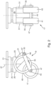
wheel assemblies 19 arranged in thebottom surface 7 of thecargo support 1 offigure 1 is shown in detail infigure 2 . As can be taken fromfigure 2 thewheel assembly 19 comprises amount member 21 which is configured to be fixedly attached in a recess in thebottom surface 7 of thebase member 3. On the bottom side of the mount member21a carrier member 23 is rotatably mounted via abearing 25 so that thecarrier member 23 may rotate about theamount member 21 about a steeringaxis 27. In the present embodiment thecarrier member 23 may rotate and not just pivot relative to themount member 21. However, for the present invention it would suffice when just a pivot movement within a limited angular range would be possible for thecarrier member 23. - The
carrier member 23 comprises acoupling section 29 which when looking at the cross-section parallel to the steeringaxis 27 essentially extends perpendicularly to the steeringaxis 27 and is rotatably coupled to themount member 21. Attached to thecoupling section 29 arearm sections 31, which extend away from themount member 21, thearm sections 31 having adistal end 33 at whicharm members 35 are pivotably mounted via abolt member 37 so that thearm members 35 may pivot relative to thearm sections 31 and hence thecarrier member 23 about apivot axis 39 extending perpendicularly to the steeringaxis 27. Thepivot axis 39 also extends in parallel to thecommon support plane 15. Thecarrier member 23 and thearm members 35 form a carrier assembly which is rotatable relative to themount member 21 and which rotatably supports thewheel member 17. - Whereas a first end of the
arm members 35 is pivotably coupled to thearm sections 31 and hence thecarrier member 23, a second end of thearm members 35 opposite the first end carries thewheel member 17 wherein in this preferred embodiment thewheel member 17 comprises afirst wheel 41 and asecond wheel 43 which are supported by ashaft member 45 that defines therotational axis 47 about which thewheels wheel member 17 may rotate. As can be seen infigure 2 therotational axis 47 and thepivot axis 39 are parallel to each other. - Moreover, as can be taken from
figure 2 , the projection of therotation axis 47 on thecommon support plane 15 is spaced from the point where the steeringaxis 27 intersects thecommon support plane 15. Hence, when seen in thesupport plane 15 therotation axis 47 and the steeringaxis 27 are at a distance from each other or spaced apart, and thewheels axis 27. Such arrangement has the advantage that when thecargo support 1 is maneuvered along a certain predetermined direction thewheel members 17 will align themselves with this direction. - Finally, as shown in
figure 2 thewheel assembly 19 comprises a biasing member in the form of aring member 49, which in this preferred embodiment is circular and formed of steel. Thering member 49 is supported on the one hand by thebolt member 37 and theshaft member 45 and on the other hand by thecoupling section 29. Further, thering member 49 is arranged between the first andsecond wheels ring member 49 extends in a plane perpendicular to the pivot axis (39), - So, the
ring member 49 is arranged between thecarrier member 23 and thearm member 35 and supported on thearm member 39 at a point spaced from thepivot axis 39 and on thecarrier member 23 such that when thearm member 35 pivots towards themount member 21, thering member 49 is elastically deformed. - When the
ring member 49 is in the un-deformed state as shown infigure 2 , thewheels common support plane 15, as can be seen infigure 1 . However, when a sufficiently high force acts on thewheels coupling section 29 and themount member 21, thering member 49 will elastically be deformed and thearm members 35 pivot towards thecoupling section 29 so that thewheels support plane 15 towards thesupport surface 5 and they do not extend beyond thesupport plane 15 but are received in the recesses in thebase member 3 and assume a retracted position. However, when thewheels ring member 49 acts as a biasing member which applies a biasing force to thewheels - Thus, the position of the
wheels ring member 49, the biasing force mainly acting along the steeringaxis 27. - The
ring member 49 is dimensioned in such a manner that the biasing force it applies to thewheel member 17 and thewheels axis 27 towards the extended position has such a magnitude that it exceeds the maximum gravitational force by 50 % at most which acts on thewheel member 17 and forces it towards the retracted position when all thewheel members 17 of thecargo support 1 are placed on thefloor surface 11 and one or more cargo elements are placed on thesupport surface 5 having the maximum allowable weight of the one or more cargo elements for the cargo support. It is preferred when the biasing member in the form of thering member 49 is configured such that the biasing force it applies exceeds the maximum gravitational force by 40 % at most, more preferably by just 30 % at most. With such preferred configuration thewheel assembly 19 is even more sensitive to situations where the applied forces exceed the limit at which thefloor 11 on which thecargo support 1 is currently resting, may be damaged. - Thus, when the
support surface 5 of the embodiment of thecargo support 1 carries a cargo element having the maximum allowable weight for thecargo support 1, thewheel members 17 will still be in the extended position and project beyond thecommon support plane 15, so that thecargo support 1 can be maneuvered over afloor surface 9 with thewheels surface 9. However, when the embodiment of thecargo support 1 is subjected to additional forces, e.g., during landing, which act also parallel to the steeringaxis 27 and which add up to the already mentioned gravitational forces, the biasing force of thering member 49 is exceeded, so that thewheel members 17 will move from the extended position to the retracted position, and thesupport sections 13 on thebottom surface 7 of thebase member 3 will come into contact with thefloor surface 9, as it is shown infigure 6 a) . Thus, theentire cargo support 1 is then no longer supported by thewheel members 17 only but by thesupport sections 13, so that high point loads to which thefloor surface 9 will be subjected at the positions of thewheels cargo unit 1 is then transferred to thefloor surface 11 via thesupport sections 13 having a much larger contact surface. -
Figures 3 and4 show an alternative configuration of thewheel assembly 19 to be mounted in thebottom surface 7 of thebase member 3. However, this second alternative does not essentially differ from the first alternative shown infigure 2 . It also comprises amount member 21 which is adapted to be fixedly mounted on thebase member 3. Rotatably coupled to themount member 21 about a steeringaxis 27 is acarrier member 23 comprising acoupling section 29 andarm sections 31, thecoupling section 29 extending essentially perpendicularly to the steeringaxis 27 and thearm sections 31 extending away from themount member 21 and having a distal end spaced from thecoupling section 29 along the steeringaxis 27. - At the distal end of the
arm sections 31arm members 35 are pivotably supported about apivot axis 39 viabolt members 37. Hence, also in this case the first end of thearm members 35 is supported at the distal end of thearm sections 31 by means ofbolt members 37, and the second end of thearm members 35 carriesshaft members 45 which define a rotational axis for first andsecond wheels shaft members 45 and which form awheel member 17. As can further be taken from the left part offigure 4 , therotational axis 47 is spaced from the steeringaxis 27 when seen in thesupport plane 15, so that also in this alternative therotational axis 47 is eccentrically arranged relative to the steeringaxis 27. - As can be taken from
figures 3 and4 , both thebolt members 37 and theshaft members 45 each carry abracket ring member 49 which also in this alternative acts as a biasing member is supported in thebrackets ring member 49, which is also arranged between thewheels bolt members 37 and theshaft members 45 but carried byadditional brackets bolt members 37 and theshaft members 45 only indirectly carry thering member 49. - In this second alternative the
ring member 49 is also dimensioned such that the biasing force it applies to thewheels axis 27 towards the extended position has such a magnitude that it exceeds that force by X % at most which acts on thewheel member 17 and forces it towards the retracted position when all thewheel members 17 of thecargo support 1 are placed on thefloor surface 11 and cargo elements having the maximum allowable weight are placed on thesupport surface 5. Therefore, when using this second alternative of awheel assembly 19 in thecargo support 1 the same behavior as described above will be achieved, i.e., when in addition to the gravitational forces further inertia forces act in the direction of the steeringaxis 27, thewheel members 17 will be pushed towards the retracted position against the biasing force applied by the ring member, and thesupport sections 13 will get into contact with the floor surface so as to reduce the point loads. - Finally,
figure 5 shows a further alternative of awheel assembly 19 to be coupled with thebase member 3 of thecargo unit 1 of the present invention. - It also comprises a
mount member 21 which is adapted to be fixedly mounted on thebase member 3. Acarrier member 23 comprising acoupling section 29 andarm sections 31 is rotatably coupled to themount member 21 about a steeringaxis 27 via abearing 25. Thecoupling section 29 extends essentially perpendicularly to the steeringaxis 27 and thearm sections 31 project away from themount member 21 and have a distal end spaced from thecoupling section 29 along the steeringaxis 27. On the distal ends of thearm sections 31arm members 35 are pivotably supported about apivot axis 39 viabolt members 37. So, also in this third alternative the first end of thearm members 35 is supported at the distal end of thearm sections 31 by means ofbolt members 37, and the second end of thearm members 35 carries ashaft member 45 which defines arotational axis 47 for first andsecond wheels shaft member 45 and which form awheel member 17. - As can further be taken from
figure 5 , therotational axis 47 is spaced from the steeringaxis 27 when seen in thesupport plane 15, so that also in this third alternative therotational axis 47 is eccentrically arranged relative to the steeringaxis 27. - In this third alternative of a wheel assembly 19 a
gas spring 55 is employed as a biasing member rather than a ring member, thegas spring 55 being arranged between the distal end of the arm member and 35 and thearm section 31. In particular, thegas spring 55 is coupled to the distal end of thearm member 35 via theshaft member 45, which also carries one end of thegas spring 55. Thus, it is also possible to use linearly acting biasing members for applying the biasing force onto thewheel members 17. - In particular, also in this third alternative the biasing member in the form of the
gas spring 35 is dimensioned such that the biasing force it applies to thewheels axis 27 towards the extended position has such a magnitude that it exceeds that force by X % at most which acts on thewheel member 17 and forces it towards the retracted position when all thewheel members 17 of thecargo support 1 are placed on thefloor surface 11 and cargo elements having the maximum allowable weight are placed on thesupport surface 5. - Therefore, when using also this third alternative of a
wheel assembly 19 in thecargo support 1 the same behavior as described above will be achieved, i.e., when in addition to the gravitational forces further inertia forces act in the direction of the steeringaxis 27, thewheel members 17 will be pushed towards the retracted position against the biasing force applied by the ring member, and thesupport sections 13 will get into contact with the floor surface so as to reduce the point loads. - Besides the scenario described with respect to
figures 1 and6 a ) other scenarios are also conceivable where the afore-mentioned configuration withwheel assemblies 19 havingwheels members 17 that are forced towards an extended position via a biasing member that is chosen such that the force it applies exceeds the gravitational forces by only a small amount, prevents sections of a floor from being damaged by high point loads applied by thewheel members 17. - As it is shown in
figures 6b ) and7a ) thecargo support 1 may also be positioned above seat rails 57 in thefloor 11 havinglocking members 59 inserted therein, wherein thecargo unit 1 is positioned such that the lockingmembers 59 engage with recesses in thesupport section 13 of thecargo unit 1 and prevent thecargo unit 1 from being moved relative to thefloor surface 9. When in such case in addition to the gravitational forces due to the weight of cargo elements arranged on thesupport surface 5 further inertia forces act on thecargo support 1 in a direction parallel to the steeringaxis 27, thewheel members 17 of thewheel assemblies 19 are pushed towards the retracted position since the biasing force generated by the biasing the members does not suffice anymore to keep thesupport sections 13 spaced from the seat rails 57. Instead, thesupport sections 13 approach the seat rails 57 and get into contact with them. Hence, when large forces occur in such situation, a high point loads due to thewheel members 17 are avoided since thesupport sections 13 contact the seat rails 57. - Finally, in
figure 7b ) another situation is shown in which with thecargo unit 1 of the present invention it can be avoided that high point loads are applied onto afloor surface 9 by thewheel members 17. In this case somewheel members 17 ofwheel assemblies 19 are positioned on alight strip 61 orseat rail 57. However, due to the choice of the biasing force of thewheel assemblies 19 positioned on the rails, therespective wheel members 17 will be pushed towards the retracted position so that theother wheel members 17 will still contact thefloor surface 9. - As can be taken from the above, with the embodiment of a
cargo support 1 according to the present invention it is prevented that high point loads due to thewheel members 17 on thebottom surface 7 of thecargo support 1 are applied to thefloor surface 9 supporting thecargo support 1. In particular, it is not required that thewheel members 17 are actively retracted. Instead, the mechanism of the present invention with a biasing member being chosen in the aforementioned way does not require an active adjustment of the wheel assemblies. -
- 1
- cargo support
- 3
- base member
- 5
- support surface
- 7
- bottom surface
- 9
- floor surface
- 11
- floor
- 13
- support section
- 15
- support plane
- 17
- wheel member
- 19
- wheel assembly
- 21
- mount member
- 23
- carrier member
- 25
- bearing
- 27
- steering axis
- 29
- coupling section
- 31
- arm section
- 33
- distal end
- 35
- arm member
- 37
- bolt member
- 39
- pivot axis
- 41
- first wheel
- 43
- second wheel
- 45
- shaft member
- 47
- rotational axis
- 49
- ring member
- 51
- bracket
- 53
- bracket
- 55
- gas spring
- 57
- seat rail
- 59
- locking member
- 61
- light strip
Claims (10)
- A movable cargo support (1) for being received in the cargo hold or passenger cabin of an aircraft comprising:a base member (3) having a support surface (5) and a bottom surface (7) opposite the support surface (5),wherein the support surface (5) is adapted to support one or more cargo elements,wherein the bottom surface (7) comprises one or more support sections (13), which are adapted to support the base member (3) on a floor surface (9), andwherein the one or more support sections (13) extend in a common support plane (15),wherein the base member (3) comprises a plurality of wheel assemblies (19),wherein each wheel assembly (19) comprises a wheel member (17) which may rest on a floor surface (9) and is rotatable about a rotation axis (47) that is parallel to the support plane (15), the wheel member (17) being movably mounted on the base member (3) such- that it may pivot about a steering axis (27) of that wheel assembly (19) which steering axis (27) extends perpendicularly to the support plane (15) and- that its position parallel to the steering axis (27) may be altered between an extended position and a retracted position,wherein in the extended position the wheel member (17) protrudes beyond the support plane (15),wherein in the retracted position the wheel member is retracted from the support plane (15) towards the support surface (Ziffer 5), so that it does not extend beyond the support plane (15),wherein each wheel assembly (19) comprises a biasing member (49, 55) biasing the wheel member (17) towards the extended position with a biasing force acting in the direction of the steering axis (27), andwherein the biasing member (49, 55) is configured such that the biasing force is higher than the maximum gravitational force which acts on the wheel member (47) and forces it towards the retracted position when the wheel members (47) are placed on a horizontal floor surface (9) and one or more cargo elements are placed on the support surface (5) having the maximum allowable weight of the one or more cargo elements for the cargo support (1) and wherein the biasing force exceeds the maximum gravitational force by 50 % at most.
- The cargo support of claim 1, wherein the biasing member (49, 55) is configured such that the biasing force exceeds the maximum gravitational force by 40 % at most, preferably 30 % at most, which acts on the wheel member (17) and pushes it towards the retracted position when the wheel members (17) are placed on a floor surface (9) and one or more cargo elements are placed on the support surface (5) having the maximum allowable weight of the one or more cargo elements for the cargo support (i).
- The cargo support of claim 1 or 2, wherein in each wheel assembly (19) the steering axis (27) and the rotation axis (47) are arranged such that when seen in the support plane (15) the rotation axis (47) is at a distance from the steering axis (27).
- The cargo support of one or more of claims 1 to 3, wherein each wheel assembly (19) comprises a mount member (21) fixedly supported on the base member (3) and a carrier assembly,wherein the carrier assembly is rotatably supported on the mount member (21) about the steering axis (27) of the wheel assembly (19), andwherein the wheel member (17) of the wheel assembly (19) is rotatably supported about the rotation axis (47) on the carrier assembly.
- The cargo support of claim 4, wherein the carrier assembly comprises a carrier member (23) rotatably coupled to the mount member (21) about the steering axis (27), and an arm member (35),wherein a first end of the arm member (35) is pivotably connected to the carrier member (23) about a pivot axis (39) which is parallel to the rotational axis (47), and a second end of the arm member (35) opposite the first end carries the wheel member (17), andwherein the biasing member (49, 55) is arranged between the carrier member (23) and the arm member (35).
- The cargo support of claim 5, wherein the wheel member (17) comprises a first wheel (41) and a second wheel (43) which are spaced along the rotational axis (47) and supported on a shaft member (45), and
wherein the arm member (35) and/or the biasing member (49, 55) extends between the first and second wheels (41, 43). - The cargo support of claim 5 or 6, wherein the biasing member is formed as a gas spring (55) or helical spring extending between the carrier member (23) and the arm member (35).
- The cargo support of claim 5 or 6, wherein the biasing member is formed as ring member, preferably a circular ring member,wherein the ring member (49) extends in a plane perpendicular to the pivot axis (39),wherein the ring member (49) is arranged between the carrier member (23) and the arm member (35),wherein the ring member (49) is supported on the arm member (35) at a point spaced from the pivot axis (39) and on the carrier member (23) such that when the arm member (35) pivots towards the mount member (21), the ring member (49) is elastically deformed.
- The cargo support of claim 8, wherein when seen along the pivot axis (39) the cross section of the carrier member (23) has a coupling section (29) extending perpendicularly to the steering axis (27) and being rotatably coupled to the mount member (21), and an arm section (31) extending away from the mount member (21) with a distal end spaced from the coupling section (29) along the steering axis (27),wherein the first end of the arm member (35) is pivotably coupled to the distal end of the arm section (31), andwherein the ring member (49) is supported on the coupling section (29).
- The cargo support of claim 8 or 9, wherein the first end of the arm member (35) is coupled to the carrier member (23) by a bolt member (37),wherein the wheel member (17) comprises a shaft member (45) which is carried by the arm member (35) at its second end, andwherein the ring member (39) is supported via the bolt member (37) and the shaft member (45).
Priority Applications (2)
| Application Number | Priority Date | Filing Date | Title |
|---|---|---|---|
| EP22165946.9A EP4253233B1 (en) | 2022-03-31 | 2022-03-31 | Movable cargo support having vertically biased wheel members |
| US18/191,210 US12583587B2 (en) | 2022-03-31 | 2023-03-28 | Movable cargo support having vertically biased wheel members |
Applications Claiming Priority (1)
| Application Number | Priority Date | Filing Date | Title |
|---|---|---|---|
| EP22165946.9A EP4253233B1 (en) | 2022-03-31 | 2022-03-31 | Movable cargo support having vertically biased wheel members |
Publications (2)
| Publication Number | Publication Date |
|---|---|
| EP4253233A1 true EP4253233A1 (en) | 2023-10-04 |
| EP4253233B1 EP4253233B1 (en) | 2024-12-25 |
Family
ID=81325495
Family Applications (1)
| Application Number | Title | Priority Date | Filing Date |
|---|---|---|---|
| EP22165946.9A Active EP4253233B1 (en) | 2022-03-31 | 2022-03-31 | Movable cargo support having vertically biased wheel members |
Country Status (2)
| Country | Link |
|---|---|
| US (1) | US12583587B2 (en) |
| EP (1) | EP4253233B1 (en) |
Citations (3)
| Publication number | Priority date | Publication date | Assignee | Title |
|---|---|---|---|---|
| GB624303A (en) * | 1947-07-01 | 1949-06-01 | Spencer Heath & George Ltd | Improved retractable castor mechanisms |
| JP2004284528A (en) * | 2003-03-24 | 2004-10-14 | Sanki Kogyo:Kk | caster |
| WO2019229844A1 (en) * | 2018-05-29 | 2019-12-05 | 芝海株式会社 | Cargo container |
Family Cites Families (1)
| Publication number | Priority date | Publication date | Assignee | Title |
|---|---|---|---|---|
| USH1767H (en) * | 1996-06-11 | 1999-01-05 | The United States Of America As Represented By The Secretary Of The Army | Device to improve the mobility of towed howitzers |
-
2022
- 2022-03-31 EP EP22165946.9A patent/EP4253233B1/en active Active
-
2023
- 2023-03-28 US US18/191,210 patent/US12583587B2/en active Active
Patent Citations (3)
| Publication number | Priority date | Publication date | Assignee | Title |
|---|---|---|---|---|
| GB624303A (en) * | 1947-07-01 | 1949-06-01 | Spencer Heath & George Ltd | Improved retractable castor mechanisms |
| JP2004284528A (en) * | 2003-03-24 | 2004-10-14 | Sanki Kogyo:Kk | caster |
| WO2019229844A1 (en) * | 2018-05-29 | 2019-12-05 | 芝海株式会社 | Cargo container |
Also Published As
| Publication number | Publication date |
|---|---|
| US20240116633A1 (en) | 2024-04-11 |
| EP4253233B1 (en) | 2024-12-25 |
| US12583587B2 (en) | 2026-03-24 |
Similar Documents
| Publication | Publication Date | Title |
|---|---|---|
| US9227529B2 (en) | Utility vehicle seat with a rotation adjustment device overload protection unit | |
| US6691971B2 (en) | Seat slide device | |
| US5803523A (en) | Extendable support system | |
| US5052878A (en) | Retractable bed for truck | |
| US4854790A (en) | Vehicle wheel support and fastening device | |
| US5544591A (en) | Stabilized roller bearing adapter | |
| US6804850B2 (en) | Loading dock with lip protecting bumpers | |
| KR20070057777A (en) | Combination bed loading and fixing system | |
| US3685872A (en) | Slide for a vehicle seat | |
| EP3385114B1 (en) | Device for longitudinal movement and adjustment of automotive vehicles seats | |
| WO2013152178A1 (en) | Adjustable decking system for supporting freight | |
| CN103998287B (en) | Control and reduce the device of seat rearward displacement for selectivity under accident conditions | |
| EP1805072B1 (en) | Railway wagon | |
| EP4253233A1 (en) | Movable cargo support having vertically biased wheel members | |
| US6520472B1 (en) | Container restraint for a parked swap body | |
| CN112272634A (en) | Railway truck assembly with friction assist side bearing | |
| EP3914057B1 (en) | Slide rail assembly | |
| GB2551158A (en) | Vehicle ramp | |
| JP2006123661A (en) | Slope device for vehicle | |
| JP5421888B2 (en) | Movable cradle for cargo vehicles | |
| CN212289608U (en) | Support device and dump truck | |
| EP4335693B1 (en) | Vehicle seat | |
| US20260008397A1 (en) | Table with movable guide element | |
| JP3965405B2 (en) | Stopper device, load receiving table using the same, and load receiving device lifting device | |
| JP4586143B2 (en) | loader |
Legal Events
| Date | Code | Title | Description |
|---|---|---|---|
| PUAI | Public reference made under article 153(3) epc to a published international application that has entered the european phase |
Free format text: ORIGINAL CODE: 0009012 |
|
| STAA | Information on the status of an ep patent application or granted ep patent |
Free format text: STATUS: THE APPLICATION HAS BEEN PUBLISHED |
|
| AK | Designated contracting states |
Kind code of ref document: A1 Designated state(s): AL AT BE BG CH CY CZ DE DK EE ES FI FR GB GR HR HU IE IS IT LI LT LU LV MC MK MT NL NO PL PT RO RS SE SI SK SM TR |
|
| STAA | Information on the status of an ep patent application or granted ep patent |
Free format text: STATUS: REQUEST FOR EXAMINATION WAS MADE |
|
| 17P | Request for examination filed |
Effective date: 20240320 |
|
| RBV | Designated contracting states (corrected) |
Designated state(s): AL AT BE BG CH CY CZ DE DK EE ES FI FR GB GR HR HU IE IS IT LI LT LU LV MC MK MT NL NO PL PT RO RS SE SI SK SM TR |
|
| GRAP | Despatch of communication of intention to grant a patent |
Free format text: ORIGINAL CODE: EPIDOSNIGR1 |
|
| STAA | Information on the status of an ep patent application or granted ep patent |
Free format text: STATUS: GRANT OF PATENT IS INTENDED |
|
| INTG | Intention to grant announced |
Effective date: 20240719 |
|
| GRAS | Grant fee paid |
Free format text: ORIGINAL CODE: EPIDOSNIGR3 |
|
| GRAA | (expected) grant |
Free format text: ORIGINAL CODE: 0009210 |
|
| STAA | Information on the status of an ep patent application or granted ep patent |
Free format text: STATUS: THE PATENT HAS BEEN GRANTED |
|
| AK | Designated contracting states |
Kind code of ref document: B1 Designated state(s): AL AT BE BG CH CY CZ DE DK EE ES FI FR GB GR HR HU IE IS IT LI LT LU LV MC MK MT NL NO PL PT RO RS SE SI SK SM TR |
|
| REG | Reference to a national code |
Ref country code: GB Ref legal event code: FG4D |
|
| REG | Reference to a national code |
Ref country code: CH Ref legal event code: EP |
|
| REG | Reference to a national code |
Ref country code: IE Ref legal event code: FG4D |
|
| REG | Reference to a national code |
Ref country code: DE Ref legal event code: R096 Ref document number: 602022008980 Country of ref document: DE |
|
| REG | Reference to a national code |
Ref country code: LT Ref legal event code: MG9D |
|
| PG25 | Lapsed in a contracting state [announced via postgrant information from national office to epo] |
Ref country code: HR Free format text: LAPSE BECAUSE OF FAILURE TO SUBMIT A TRANSLATION OF THE DESCRIPTION OR TO PAY THE FEE WITHIN THE PRESCRIBED TIME-LIMIT Effective date: 20241225 |
|
| PG25 | Lapsed in a contracting state [announced via postgrant information from national office to epo] |
Ref country code: FI Free format text: LAPSE BECAUSE OF FAILURE TO SUBMIT A TRANSLATION OF THE DESCRIPTION OR TO PAY THE FEE WITHIN THE PRESCRIBED TIME-LIMIT Effective date: 20241225 |
|
| PG25 | Lapsed in a contracting state [announced via postgrant information from national office to epo] |
Ref country code: BG Free format text: LAPSE BECAUSE OF FAILURE TO SUBMIT A TRANSLATION OF THE DESCRIPTION OR TO PAY THE FEE WITHIN THE PRESCRIBED TIME-LIMIT Effective date: 20241225 |
|
| PG25 | Lapsed in a contracting state [announced via postgrant information from national office to epo] |
Ref country code: NO Free format text: LAPSE BECAUSE OF FAILURE TO SUBMIT A TRANSLATION OF THE DESCRIPTION OR TO PAY THE FEE WITHIN THE PRESCRIBED TIME-LIMIT Effective date: 20250325 |
|
| PG25 | Lapsed in a contracting state [announced via postgrant information from national office to epo] |
Ref country code: LV Free format text: LAPSE BECAUSE OF FAILURE TO SUBMIT A TRANSLATION OF THE DESCRIPTION OR TO PAY THE FEE WITHIN THE PRESCRIBED TIME-LIMIT Effective date: 20241225 Ref country code: GR Free format text: LAPSE BECAUSE OF FAILURE TO SUBMIT A TRANSLATION OF THE DESCRIPTION OR TO PAY THE FEE WITHIN THE PRESCRIBED TIME-LIMIT Effective date: 20250326 |
|
| PG25 | Lapsed in a contracting state [announced via postgrant information from national office to epo] |
Ref country code: RS Free format text: LAPSE BECAUSE OF FAILURE TO SUBMIT A TRANSLATION OF THE DESCRIPTION OR TO PAY THE FEE WITHIN THE PRESCRIBED TIME-LIMIT Effective date: 20250325 |
|
| REG | Reference to a national code |
Ref country code: NL Ref legal event code: MP Effective date: 20241225 |
|
| PG25 | Lapsed in a contracting state [announced via postgrant information from national office to epo] |
Ref country code: NL Free format text: LAPSE BECAUSE OF FAILURE TO SUBMIT A TRANSLATION OF THE DESCRIPTION OR TO PAY THE FEE WITHIN THE PRESCRIBED TIME-LIMIT Effective date: 20241225 |
|
| REG | Reference to a national code |
Ref country code: AT Ref legal event code: MK05 Ref document number: 1753976 Country of ref document: AT Kind code of ref document: T Effective date: 20241225 |
|
| PG25 | Lapsed in a contracting state [announced via postgrant information from national office to epo] |
Ref country code: SM Free format text: LAPSE BECAUSE OF FAILURE TO SUBMIT A TRANSLATION OF THE DESCRIPTION OR TO PAY THE FEE WITHIN THE PRESCRIBED TIME-LIMIT Effective date: 20241225 |
|
| PG25 | Lapsed in a contracting state [announced via postgrant information from national office to epo] |
Ref country code: PL Free format text: LAPSE BECAUSE OF FAILURE TO SUBMIT A TRANSLATION OF THE DESCRIPTION OR TO PAY THE FEE WITHIN THE PRESCRIBED TIME-LIMIT Effective date: 20241225 |
|
| PG25 | Lapsed in a contracting state [announced via postgrant information from national office to epo] |
Ref country code: ES Free format text: LAPSE BECAUSE OF FAILURE TO SUBMIT A TRANSLATION OF THE DESCRIPTION OR TO PAY THE FEE WITHIN THE PRESCRIBED TIME-LIMIT Effective date: 20241225 |
|
| PG25 | Lapsed in a contracting state [announced via postgrant information from national office to epo] |
Ref country code: IS Free format text: LAPSE BECAUSE OF FAILURE TO SUBMIT A TRANSLATION OF THE DESCRIPTION OR TO PAY THE FEE WITHIN THE PRESCRIBED TIME-LIMIT Effective date: 20250425 |
|
| PG25 | Lapsed in a contracting state [announced via postgrant information from national office to epo] |
Ref country code: PT Free format text: LAPSE BECAUSE OF FAILURE TO SUBMIT A TRANSLATION OF THE DESCRIPTION OR TO PAY THE FEE WITHIN THE PRESCRIBED TIME-LIMIT Effective date: 20250428 |
|
| PG25 | Lapsed in a contracting state [announced via postgrant information from national office to epo] |
Ref country code: EE Free format text: LAPSE BECAUSE OF FAILURE TO SUBMIT A TRANSLATION OF THE DESCRIPTION OR TO PAY THE FEE WITHIN THE PRESCRIBED TIME-LIMIT Effective date: 20241225 |
|
| PG25 | Lapsed in a contracting state [announced via postgrant information from national office to epo] |
Ref country code: RO Free format text: LAPSE BECAUSE OF FAILURE TO SUBMIT A TRANSLATION OF THE DESCRIPTION OR TO PAY THE FEE WITHIN THE PRESCRIBED TIME-LIMIT Effective date: 20241225 Ref country code: AT Free format text: LAPSE BECAUSE OF FAILURE TO SUBMIT A TRANSLATION OF THE DESCRIPTION OR TO PAY THE FEE WITHIN THE PRESCRIBED TIME-LIMIT Effective date: 20241225 |
|
| PG25 | Lapsed in a contracting state [announced via postgrant information from national office to epo] |
Ref country code: SK Free format text: LAPSE BECAUSE OF FAILURE TO SUBMIT A TRANSLATION OF THE DESCRIPTION OR TO PAY THE FEE WITHIN THE PRESCRIBED TIME-LIMIT Effective date: 20241225 |
|
| PG25 | Lapsed in a contracting state [announced via postgrant information from national office to epo] |
Ref country code: CZ Free format text: LAPSE BECAUSE OF FAILURE TO SUBMIT A TRANSLATION OF THE DESCRIPTION OR TO PAY THE FEE WITHIN THE PRESCRIBED TIME-LIMIT Effective date: 20241225 |
|
| PG25 | Lapsed in a contracting state [announced via postgrant information from national office to epo] |
Ref country code: IT Free format text: LAPSE BECAUSE OF FAILURE TO SUBMIT A TRANSLATION OF THE DESCRIPTION OR TO PAY THE FEE WITHIN THE PRESCRIBED TIME-LIMIT Effective date: 20241225 |
|
| PG25 | Lapsed in a contracting state [announced via postgrant information from national office to epo] |
Ref country code: SE Free format text: LAPSE BECAUSE OF FAILURE TO SUBMIT A TRANSLATION OF THE DESCRIPTION OR TO PAY THE FEE WITHIN THE PRESCRIBED TIME-LIMIT Effective date: 20241225 |
|
| REG | Reference to a national code |
Ref country code: DE Ref legal event code: R097 Ref document number: 602022008980 Country of ref document: DE |
|
| PG25 | Lapsed in a contracting state [announced via postgrant information from national office to epo] |
Ref country code: DK Free format text: LAPSE BECAUSE OF FAILURE TO SUBMIT A TRANSLATION OF THE DESCRIPTION OR TO PAY THE FEE WITHIN THE PRESCRIBED TIME-LIMIT Effective date: 20241225 |
|
| PG25 | Lapsed in a contracting state [announced via postgrant information from national office to epo] |
Ref country code: MC Free format text: LAPSE BECAUSE OF FAILURE TO SUBMIT A TRANSLATION OF THE DESCRIPTION OR TO PAY THE FEE WITHIN THE PRESCRIBED TIME-LIMIT Effective date: 20241225 |
|
| REG | Reference to a national code |
Ref country code: CH Ref legal event code: H13 Free format text: ST27 STATUS EVENT CODE: U-0-0-H10-H13 (AS PROVIDED BY THE NATIONAL OFFICE) Effective date: 20251023 |
|
| PLBE | No opposition filed within time limit |
Free format text: ORIGINAL CODE: 0009261 |
|
| STAA | Information on the status of an ep patent application or granted ep patent |
Free format text: STATUS: NO OPPOSITION FILED WITHIN TIME LIMIT |
|
| PG25 | Lapsed in a contracting state [announced via postgrant information from national office to epo] |
Ref country code: LU Free format text: LAPSE BECAUSE OF NON-PAYMENT OF DUE FEES Effective date: 20250331 |
|
| 26N | No opposition filed |
Effective date: 20250926 |
|
| REG | Reference to a national code |
Ref country code: BE Ref legal event code: MM Effective date: 20250331 |
|
| PG25 | Lapsed in a contracting state [announced via postgrant information from national office to epo] |
Ref country code: BE Free format text: LAPSE BECAUSE OF NON-PAYMENT OF DUE FEES Effective date: 20250331 |
|
| PG25 | Lapsed in a contracting state [announced via postgrant information from national office to epo] |
Ref country code: CH Free format text: LAPSE BECAUSE OF NON-PAYMENT OF DUE FEES Effective date: 20250331 |
|
| PG25 | Lapsed in a contracting state [announced via postgrant information from national office to epo] |
Ref country code: IE Free format text: LAPSE BECAUSE OF NON-PAYMENT OF DUE FEES Effective date: 20250331 |
|
| PGFP | Annual fee paid to national office [announced via postgrant information from national office to epo] |
Ref country code: DE Payment date: 20260319 Year of fee payment: 5 |
|
| PGFP | Annual fee paid to national office [announced via postgrant information from national office to epo] |
Ref country code: FR Payment date: 20260323 Year of fee payment: 5 |