EP4253199A1 - Vehicle body front structure and vehicle - Google Patents
Vehicle body front structure and vehicle Download PDFInfo
- Publication number
- EP4253199A1 EP4253199A1 EP21897155.4A EP21897155A EP4253199A1 EP 4253199 A1 EP4253199 A1 EP 4253199A1 EP 21897155 A EP21897155 A EP 21897155A EP 4253199 A1 EP4253199 A1 EP 4253199A1
- Authority
- EP
- European Patent Office
- Prior art keywords
- longitudinal beam
- front longitudinal
- plate
- support member
- support
- Prior art date
- Legal status (The legal status is an assumption and is not a legal conclusion. Google has not performed a legal analysis and makes no representation as to the accuracy of the status listed.)
- Pending
Links
Images


Classifications
-
- B—PERFORMING OPERATIONS; TRANSPORTING
- B62—LAND VEHICLES FOR TRAVELLING OTHERWISE THAN ON RAILS
- B62D—MOTOR VEHICLES; TRAILERS
- B62D25/00—Superstructure or monocoque structure sub-units; Parts or details thereof not otherwise provided for
- B62D25/08—Front or rear portions
-
- B—PERFORMING OPERATIONS; TRANSPORTING
- B62—LAND VEHICLES FOR TRAVELLING OTHERWISE THAN ON RAILS
- B62D—MOTOR VEHICLES; TRAILERS
- B62D21/00—Understructures, i.e. chassis frame on which a vehicle body may be mounted
- B62D21/15—Understructures, i.e. chassis frame on which a vehicle body may be mounted having impact absorbing means, e.g. a frame designed to permanently or temporarily change shape or dimension upon impact with another body
- B62D21/152—Front or rear frames
- B62D21/155—Sub-frames or underguards
-
- B—PERFORMING OPERATIONS; TRANSPORTING
- B62—LAND VEHICLES FOR TRAVELLING OTHERWISE THAN ON RAILS
- B62D—MOTOR VEHICLES; TRAILERS
- B62D21/00—Understructures, i.e. chassis frame on which a vehicle body may be mounted
- B62D21/15—Understructures, i.e. chassis frame on which a vehicle body may be mounted having impact absorbing means, e.g. a frame designed to permanently or temporarily change shape or dimension upon impact with another body
- B62D21/152—Front or rear frames
-
- B—PERFORMING OPERATIONS; TRANSPORTING
- B62—LAND VEHICLES FOR TRAVELLING OTHERWISE THAN ON RAILS
- B62D—MOTOR VEHICLES; TRAILERS
- B62D27/00—Connections between superstructure or understructure sub-units
- B62D27/02—Connections between superstructure or understructure sub-units rigid
- B62D27/023—Assembly of structural joints
-
- B—PERFORMING OPERATIONS; TRANSPORTING
- B62—LAND VEHICLES FOR TRAVELLING OTHERWISE THAN ON RAILS
- B62D—MOTOR VEHICLES; TRAILERS
- B62D25/00—Superstructure or monocoque structure sub-units; Parts or details thereof not otherwise provided for
- B62D25/08—Front or rear portions
- B62D25/082—Engine compartments
Definitions
- the present disclosure relates to the technical field of vehicles, and in particular, to a vehicle body front structure and a vehicle.
- the embodiments of the present disclosure provide a vehicle body front structure and a vehicle.
- a vehicle body front structure including: a front longitudinal beam assembly, including a front longitudinal beam inner plate, a front longitudinal beam cover plate, and a front longitudinal beam support member, the front longitudinal beam inner plate including a longitudinal beam bottom plate and two longitudinal beam side plates, wherein the two longitudinal beam side plates are respectively connected to two opposite side edges of the longitudinal beam bottom plate, and are connected to the front longitudinal beam cover plate, the front longitudinal beam cover plate is opposite to the longitudinal beam bottom plate, a first portion of the front longitudinal beam support member is in a groove enclosed by the longitudinal beam bottom plate and the longitudinal beam side plates, a second portion of the front longitudinal beam support member is outside the groove, the first portion is connected to the longitudinal beam bottom plate and the longitudinal beam side plates, and a surface of the front longitudinal beam support member is connected to a side edge of the front longitudinal beam cover plate; and a front wheel cover side reinforcement beam connected to the second portion.
- a front longitudinal beam assembly including a front longitudinal beam inner plate, a front longitudinal beam cover plate, and a front longitudinal beam support member
- a length of the front longitudinal beam cover plate is less than a length of the longitudinal beam side plate in a length direction of the longitudinal beam side plate, and the first portion is on and connected to the side edge of the front longitudinal beam cover plate and is connected to the side edge of the front longitudinal beam cover plate.
- the front longitudinal beam support member includes a support bottom plate and two support side plates, wherein the two support side plates are respectively connected to two opposite side edges of the support bottom plate, a side edge of the support bottom plate is connected to a surface of the longitudinal beam bottom plate, a surface of the support bottom plate is connected to the side edge of the front longitudinal beam cover plate, the support side plates are parallel to the longitudinal beam side plates and are attached to the longitudinal beam side plates.
- the support bottom plate has two opposite first side edges and two opposite second side edges, two ends of each of the first side edges are respectively connected to the two second side edges, and the two support side plates are respectively connected to the two first side edges; and a first connection flange is arranged on the two second side edges, a portion of the first connection flange in the groove is attached to the longitudinal beam bottom plate, and a portion of the first connection flange outside the groove is attached to the front wheel cover side reinforcement beam.
- a second connection flange is arranged on the support side plate, wherein the second connection flange and the support bottom plate are on opposite sides of the support side plate, and the second connection flange is opposite to a side edge of the longitudinal beam side plate and is connected to the side edge of the longitudinal beam side plate.
- the vehicle body front structure further includes a support structure connected to the front longitudinal beam cover plate and the front longitudinal beam support member.
- the support structure includes a support connection plate having two opposite third side edges and two opposite fourth side edges, wherein two ends of each of the third side edges are respectively connected to the two fourth side edges, and the two third side edges are respectively connected to the surface of the front longitudinal beam support member and a surface of the front longitudinal beam cover plate.
- the support structure further includes two connection side plates respectively connected to the two fourth side edges, wherein the connection side plates are connected to the surface of the front longitudinal beam support member and the surface of the front longitudinal beam cover plate.
- a third connection flange is arranged on the longitudinal beam side plate, wherein the third connection flange and the longitudinal beam bottom plate are on opposite sides of the longitudinal beam side plate, and the third connection flange is attached to the front longitudinal beam cover plate.
- a fourth connection flange is arranged on the side edge of the front longitudinal beam cover plate, wherein the fourth connection flange is opposite to the front longitudinal beam support member, and the fourth connection flange is attached to the front longitudinal beam support member.
- the vehicle body front structure further includes a front baffle plate, wherein a first end of the front longitudinal beam inner plate is connected to the front baffle plate and is distal from the front longitudinal beam support member, a first end of the front longitudinal beam cover plate is connected to the front baffle plate and is distal from the front longitudinal beam support member, and a first end of the front wheel cover side reinforcement beam is connected to the front baffle plate and is distal from the front longitudinal beam support member.
- the vehicle body front structure includes two front longitudinal beam assemblies and two front wheel cover side reinforcement beams, wherein the two front longitudinal beam assemblies and the two front wheel cover side reinforcement beams are symmetrically on two sides of the front baffle plate.
- the front longitudinal beam support member is fastened to the front longitudinal beam cover plate by welding
- the front longitudinal beam inner plate is fastened to the front longitudinal beam cover plate by welding
- a vehicle includes the foregoing vehicle body front structure.
- the length of the front longitudinal beam cover plate is less than the length of the longitudinal beam side plate in the length direction of the longitudinal beam side plate, the first portion is on the side edge of the front longitudinal beam cover plate and is connected to the side edge of the front longitudinal beam cover plate.
- the front longitudinal beam support member includes the support bottom plate and the two support side plates, wherein the two support side plates are respectively connected to the two opposite side edges of the support bottom plate, the side edge of the support bottom plate is connected to the surface of the longitudinal beam bottom plate, the surface of the support bottom plate is connected to the side edge of the front longitudinal beam cover plate, the support side plates are parallel to the longitudinal beam side plates, and the support side plates are attached to the longitudinal beam side plates.
- the vehicle body front structure further includes the support structure connected to the front longitudinal beam cover plate and the front longitudinal beam support member.
- the portion of the front longitudinal beam support member is in the groove of the front longitudinal beam inner plate.
- the portion of the front longitudinal beam support member in the groove is connected to the longitudinal beam bottom plate and the longitudinal beam side plates.
- the front wheel cover side reinforcement beam is connected to the portion of the front longitudinal beam support member outside the groove. In this way, in the case that the front wheel cover side reinforcement beam is subjected to a small overlap crash, the front wheel cover side reinforcement beam transfers energy to the front longitudinal beam inner plate through the front longitudinal beam support member after being subjected to a force.
- a force-bearing point of the front longitudinal beam inner plate is at the longitudinal beam bottom plate and the longitudinal beam side plates, that is, the force-bearing position is inside the front longitudinal beam assembly.
- the front longitudinal beam assembly In comparison with the related art in which a connection plate is directly connected to an outer side wall of a front longitudinal beam, in the embodiments of the present disclosure, in the case that the front longitudinal beam assembly bears a force, side walls of the front longitudinal beam assembly share an external force, avoiding the situation that the outer side wall of the front longitudinal beam is subjected to excessive local force. Therefore, the front longitudinal beam is not easy to bend, such that the front longitudinal beam assembly can effectively transfer energy, impact resistance of the front longitudinal beam assembly is improved, deformation of a passenger compartment is reduced, and safety is improved.
- a solution to a 25% small overlap crash is mainly to add a connector on a side wall of a front longitudinal beam, and a front wheel cover side reinforcement beam is connected to the connector, to transfer an impact force applied to the front wheel cover side reinforcement beam to the front longitudinal beam through the connector.
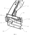
- FIG. 1 is a schematic diagram of a vehicle body front structure according to some embodiments of the present disclosure.
- the vehicle body front structure includes a front longitudinal beam assembly 1 and a front wheel cover side reinforcement beam 2.
- the front longitudinal beam assembly 1 is connected to the front wheel cover side reinforcement beam 2.
- the vehicle body front structure further includes a front baffle plate 4.
- a portion of a front longitudinal beam inner plate 11 opposite to a front longitudinal beam support member 13 is connected to the front baffle plate 4.
- a portion of a front longitudinal beam cover plate 12 opposite to the front longitudinal beam support member 13 is connected to the front baffle plate 4.
- a portion of the front wheel cover side reinforcement beam 2 opposite to the front longitudinal beam support member 13 is connected to the front baffle plate 4.
- FIG. 2 is a partially exploded view of a vehicle body front structure according to some embodiments of the present disclosure.
- the front longitudinal beam assembly 1 includes the front longitudinal beam inner plate 11, the front longitudinal beam cover plate 12, and the front longitudinal beam support member 13.
- the front longitudinal beam inner plate 11 and the front longitudinal beam cover plate 12 are connected to the front longitudinal beam support member 13.
- the front longitudinal beam support member 13 is also connected to the front wheel cover side reinforcement beam 2.
- FIG. 3 is a schematic diagram of a partial structure of the front longitudinal beam assembly 1 according to some embodiments of the present disclosure.
- FIG. 3 shows a portion of the front longitudinal beam inner plate 11, a portion of the front longitudinal beam cover plate 12, and the front longitudinal beam support member 13 included in the front longitudinal beam assembly.
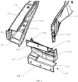
- FIG. 4 is an exploded view of the front longitudinal beam assembly 1 according to some embodiments of the present disclosure.
- the front longitudinal beam inner plate 11 includes a longitudinal beam bottom plate 111 and two longitudinal beam side plates 112 connected to opposite sides of the longitudinal beam bottom plate 111.
- the two longitudinal beam side plates 112 are connected to the front longitudinal beam cover plate 12.
- the front longitudinal beam cover plate 12 is opposite to the longitudinal beam bottom plate 111.
- a portion of the front longitudinal beam support member 13 is in a groove C enclosed by the longitudinal beam bottom plate 111 and the longitudinal beam side plates 112.
- the portion of the front longitudinal beam support member 13 in the groove C is connected to the longitudinal beam bottom plate 111 and the longitudinal beam side plates 112.
- a surface of the front longitudinal beam support member 13 is connected to a side edge of the front longitudinal beam cover plate 12. That is, a first portion of the front longitudinal beam support member 13 is in the groove C enclosed by the longitudinal beam bottom plate 111 and the longitudinal beam side plates 112, and a second portion of the front longitudinal beam support member 13 is outside the groove C.
- the first portion is connected to the longitudinal beam bottom plate 111 and the longitudinal beam side plates 112.
- the surface of the front longitudinal beam support member 13 is connected to the side edge of the front longitudinal beam cover plate 12.
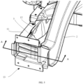
- FIG. 5 is a schematic assembly diagram of a vehicle body front structure according to some embodiments of the present disclosure. As shown in FIG. 5 , the front wheel cover side reinforcement beam 2 is connected to the portion of the front longitudinal beam support member 13 outside the groove C. That is, the front wheel cover side reinforcement beam 2 is connected to the second portion.
- the vehicle body front structure provided in the embodiments of the present disclosure includes the front longitudinal beam assembly 1 and the front wheel cover side reinforcement beam 2.
- the front longitudinal beam assembly 1 includes the front longitudinal beam inner plate 11, the front longitudinal beam cover plate 12, and the front longitudinal beam support member 13.
- the longitudinal beam bottom plate 111 and the longitudinal beam side plates 112 of the front longitudinal beam inner plate 11 make the front longitudinal beam inner plate 11 U-shaped. That is, the longitudinal beam bottom plate 111 and the longitudinal beam side plates 112 form the U-shaped groove C.
- the front longitudinal beam cover plate 12 covers an opening of the groove C of the front longitudinal beam inner plate 11 to form a stable structure with a square cross section.
- the portion of the front longitudinal beam support member 13 is in the groove C between the front longitudinal beam inner plate 11 and the front longitudinal beam cover plate 12.
- the portion of the front longitudinal beam support member 13 in the groove C is connected to the longitudinal beam bottom plate 111 and the longitudinal beam side plates 112.
- the front wheel cover side reinforcement beam 2 is connected to the portion of the front longitudinal beam support member 13 outside the groove C. In this way, in the case that the front wheel cover side reinforcement beam 2 is subjected to a small overlap crash, the front wheel cover side reinforcement beam 2 transfers energy to the front longitudinal beam inner plate 11 through the front longitudinal beam support member 13 after being subjected to a force.
- a force-bearing point of the front longitudinal beam inner plate 11 is at the longitudinal beam bottom plate 111 and the longitudinal beam side plates 112, that is, the force-bearing position is inside the front longitudinal beam assembly 1.
- a connection plate is directly connected to an outer side wall of a front longitudinal beam
- side walls of the front longitudinal beam assembly 1 share an external force, avoiding the situation that the outer side wall of the front longitudinal beam is subjected to an excessive local force.
- the front longitudinal beam assembly 1 is a stable structure with a square cross section, such that the front longitudinal beam is not easy to bend, and the front longitudinal beam assembly 1 can effectively transfer energy.
- a surface of the front longitudinal beam cover plate 12 is provided with an opening.
- the opening is on a side edge of the front longitudinal beam cover plate 12 close to the front longitudinal beam support member 13.
- the opening penetrates the surface of the front longitudinal beam cover plate 12.
- the opening communicates with the groove C.
- the front longitudinal beam support member 13 is in the opening and connected to a side edge of the opening. A portion of the front longitudinal beam support member 13 passes through the opening and is connected to the longitudinal beam bottom plate 111 and the longitudinal beam side plates 112. The other portion of the front longitudinal beam support member 13 is connected to the side edge of the front longitudinal beam cover plate 12.
- the surface of the front longitudinal beam cover plate 12 is provided with the opening as a through structure for the front longitudinal beam support member 13, such that the front longitudinal beam support member 13 passes through the opening and enter the groove C.
- the front longitudinal beam support member 13 is connected to the longitudinal beam bottom plate 111 and the longitudinal beam side plates 112.
- each side wall of the front longitudinal beam assembly 1 bears portion of the external force through the front longitudinal beam support member 13, avoiding the situation that the outer side wall of the front longitudinal beam bears an excessive local force. Therefore, the front longitudinal beam assembly 1 can effectively transfer energy.
- the opening is a groove extending from the side edge of the front longitudinal beam cover plate 12 in a length direction of the longitudinal beam bottom plate 111.
- the opening is provided on the side edge of the front longitudinal beam cover plate 12 to facilitate grooving to form the opening.
- the front longitudinal beam support member 13 seals ends of the longitudinal beam bottom plate 111 and the longitudinal beam side plates 112 to seal the groove C, such that the front longitudinal beam assembly 1 has a more stable closed structure.
- a size of the opening in a width direction of the front longitudinal beam cover plate 12 is the same as a width of the front longitudinal beam cover plate 12. That is, a length of the front longitudinal beam cover plate 12 is less than a length of the longitudinal beam side plate 112.
- the length of the front longitudinal beam cover plate 12 is less than the length of the longitudinal beam side plate 112 in a length direction of the longitudinal beam side plate 112.
- the first portion is on the side edge of the front longitudinal beam cover plate 12 and is connected to the side edge of the front longitudinal beam cover plate 12.
- the length of the front longitudinal beam cover plate 12 is set to be less than the length of the longitudinal beam side plate 112, such that the side, close to the front longitudinal beam support member 13, of the front longitudinal beam cover plate 12 has a notch exposing the groove C.
- the front longitudinal beam support member 13 is in the groove C through the notch and exactly seal the ends of the longitudinal beam bottom plate 111 and the longitudinal beam side plates 112 to seal the groove C, such that the front longitudinal beam assembly 1 has a more stable closed structure.
- the front longitudinal beam support member 13 includes a support bottom plate 131 and two support side plates 132 disposed on two opposite sides of the support bottom plate 131. That is, the two support side plates 132 are respectively connected to two opposite side edges of the support bottom plate 131. A side edge of the support bottom plate 131 is connected to a surface of the longitudinal beam bottom plate 111. A surface of the support bottom plate 131 is connected to the side edge of the front longitudinal beam cover plate 12.
- the support side plates 132 are parallel to the longitudinal beam side plates 112. The two support side plates 132 are respectively attached to the two longitudinal beam side plates 112.
- the two support side plates 132 parallel to each other are disposed on the support bottom plate 131, such that the two support side plates 132 are exactly attached to inner wall surfaces of the longitudinal beam side plates 112 in parallel to the inner wall surfaces of the longitudinal beam side plates 112, in the case that the side edge of the support bottom plate 131 is connected to the surface of the longitudinal beam bottom plate 111. That is, the connection between the front longitudinal beam support member 13 and the longitudinal beam side plate 112 is adjusted to be surface contact to improve reliability of the connection between the front longitudinal beam support member 13 and the front longitudinal beam inner plate 11 and prevent the front longitudinal beam support member 13 from being easily separated from the front longitudinal beam inner plate 11.
- the support bottom plate 131 of the front longitudinal beam support member 13 is rectangular, and the two support side plates 132 are disposed on the two opposite side edges of the support bottom plate 131.
- the support side plates 132 are perpendicularly connected to the support bottom plate 131.
- the support side plates 132 of the front longitudinal beam support member 13 are controlled to be in the groove C of the front longitudinal beam inner plate 11 and the front longitudinal beam cover plate 12 in a state of being parallel to the longitudinal beam side plates 112, such that a side edge of the front longitudinal beam support member 13 is connected to the longitudinal beam bottom plate 111 of the front longitudinal beam inner plate 11.
- the two support side plates 132 are controlled to be attached to the longitudinal beam side plates 112 to connect the front longitudinal beam support member 13 to the front longitudinal beam inner plate 11.
- the side edge of the front longitudinal beam cover plate 12 is connected to the surface of the support bottom plate 131 to form the front longitudinal beam assembly 1.
- the front longitudinal beam assembly 1 bears an external force transferred from the front longitudinal beam support member 13.
- the external force is dispersed to the longitudinal beam bottom plate 111 and the longitudinal beam side plates 112 through the front longitudinal beam support member 13, such that side walls are uniformly stressed. Therefore, the front longitudinal beam assembly 1 is not easy to bend, and can effectively transfer energy.
- the front longitudinal beam inner plate 11 and the front longitudinal beam support member 13, the front longitudinal beam support member 13 and the front longitudinal beam cover plate 12, and the front longitudinal beam inner plate 11 and the front longitudinal beam cover plate 12 are fastened to each other by welding.
- the welding is, for example, spot welding or plug welding.
- the support bottom plate 131 has two opposite first side edges and two opposite second side edges. Two ends of each of the first side edges are respectively connected to the two second side edges.
- the two support side plates 132 are respectively connected to the two first side edges.
- the two second side edges have a first connection flange 133.
- a portion of the first connection flange 133 in the groove C is attached to the longitudinal beam bottom plate 111.
- a portion of the first connection flange 133 outside the groove C is attached to the front wheel cover side reinforcement beam 2.
- the first connection flange 133 is disposed on the side plate connecting the support bottom plate 131 and the longitudinal beam bottom plate 111, such that the first connection flange 133 of the support bottom plate 131 is exactly attached to an inner wall surface of the longitudinal beam bottom plate 111 in parallel, in the case that the support bottom plate 131 is connected to the surface of the longitudinal beam bottom plate 111. That is, the connection between the support bottom plate 131 and the longitudinal beam bottom plate 111 is adjusted to be surface contact to improve reliability of the connection between the front longitudinal beam support member 13 and the front longitudinal beam inner plate 11 and prevent the front longitudinal beam support member 13 from easily falling off from the front longitudinal beam inner plate 11.
- the first connection flange 133 on the support bottom plate 131 is a perpendicular flange.
- the first connection flange 133 is disposed on a side surface of the support bottom plate 131 opposite to the support side plate 132. That is, the first connection flange 133 and the support side plate 132 are disposed on two opposite side surfaces.
- the front longitudinal beam support member 13 can more stably and reliably transfer power to the longitudinal beam bottom plate 111, such that the longitudinal beam bottom plate 111 shares an external force. Therefore, the front longitudinal beam assembly 1 is unlikely to be bent, and the front longitudinal beam assembly 1 can effectively transfer energy.
- a second connection flange 134 is disposed on a side edge of the support side plate 132 opposite to the support bottom plate 131. That is, the support side plate 132 has the second connection flange 134, and the second connection flange 134 and the support bottom plate 131 are disposed on opposite sides of the support side plate 132.
- the second connection flange 134 is opposite to and connected to the side edge of the longitudinal beam side plate 112.
- the second connection flange 134 is disposed on the side edge of the support side plate 132, and the second connection flange 134 is connected to the side edge of the longitudinal beam side plate 112, such that reliability of the connection between the front longitudinal beam support member 13 and the front longitudinal beam inner plate 11 is improved.
- two second connection flanges 134 extend in opposite directions, such that the second connection flanges 134 abut against the side edges of the longitudinal beam side plates 112, in the case that the front longitudinal beam support member 13 is connected to the front longitudinal beam inner plate 11. That is, in the case that the front longitudinal beam support member 13 and the front longitudinal beam inner plate 11 are assembled, the second connection flanges 134 abut against the side edges of the longitudinal beam side plates 112 to achieve installation and positioning of the front longitudinal beam support member 13.
- the second connection flange 134 is further provided with a connection hole.
- the second connection flange 134 is installed on another portion of a vehicle body through the connection hole to facilitate connections and assembly.
- a third connection flange 113 is disposed on a side edge of the longitudinal beam side plate 112 opposite to the longitudinal beam bottom plate 111. That is, the longitudinal beam side plate 112 has the third connection flange 113, and the third connection flange 113 and the longitudinal beam bottom plate 111 are disposed on opposite sides of the longitudinal beam side plate 112. The third connection flange 113 is attached to the front longitudinal beam cover plate 12.
- the third connection flange 113 is disposed on the longitudinal beam side plate 112 to increase a contact region between the longitudinal beam side plate 112 and the front longitudinal beam cover plate 12, such that the longitudinal beam side plate 112 is connected to the front longitudinal beam cover plate 12 more reliably.
- the front longitudinal beam cover plate 12 is prevented from easily falling off from the front longitudinal beam inner plate 11, and a square structure formed by the front longitudinal beam cover plate 12 and the front longitudinal beam inner plate 11 is more stable.
- a fourth connection flange 121 is disposed on a side edge of the front longitudinal beam cover plate 12 opposite to the front longitudinal beam support member 13. That is, the side edge of the front longitudinal beam cover plate 12 has the fourth connection flange 121, and the fourth connection flange 121 is opposite to the front longitudinal beam support member 13. The fourth connection flange 121 is attached to the front longitudinal beam support member 13.
- the fourth connection flange 121 is disposed on the front longitudinal beam cover plate 12 to increase a contact region between the front longitudinal beam cover plate 12 and the front longitudinal beam support member 13, such that the front longitudinal beam cover plate 12 is connected to the front longitudinal beam support member 13 more reliably.
- the front longitudinal beam cover plate 12 is prevented from easily falling off from the front longitudinal beam support member 13.
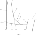
- FIG. 6 is a cross-sectional view at A-A in FIG. 5 .
- the vehicle body front structure further includes a support structure 3.
- the support structure 3 is connected to the front longitudinal beam cover plate 12 and the front longitudinal beam support member 13.
- the support structure 3 connected to the surface of the front longitudinal beam support member 13 and the surface of the front longitudinal beam cover plate 12 is disposed to jointly form a stable triangular structure to improve impact resistance of the front longitudinal beam assembly 1.
- the support structure 3 includes a support connection plate 31.
- Two opposite side edges of the support connection plate 31 parallel to the front longitudinal beam support member 13 are respectively connected to the surface of the front longitudinal beam support member 13 and the surface of the front longitudinal beam cover plate 12. That is, the support connection plate 31 has two opposite third side edges and two opposite fourth side edges. Two ends of each of the third side edges are respectively connected to the two fourth side edges.
- the support connection plate 31 has the two opposite third side edges and the two opposite fourth side edges. The two ends of each of the third side edges are respectively connected to the two fourth side edges.
- the two third side edges are respectively connected to the surface of the front longitudinal beam support member 13 and the surface of the front longitudinal beam cover plate 12.
- the support connection plate 31 connected to the surface of the front longitudinal beam support member 13 and the surface of the front longitudinal beam cover plate 12 is disposed, such that the support connection plate 31, the front longitudinal beam support member 13, and the front longitudinal beam cover plate 12 jointly form a stable triangular structure to improve the impact resistance of the front longitudinal beam assembly 1, avoiding the situation that the front longitudinal beam assembly 1 is easy to bend, improving an energy absorption effect of the vehicle body front structure, and reducing deformation of a passenger compartment, and improve safety.
- the support structure 3 further includes two connection side plates 32.
- the two connection side plates 32 are disposed on two opposite side edges of the support connection plate 31 that intersect the front longitudinal beam support member 13.
- the connection side plates 32 are connected to the surface of the front longitudinal beam support member 13 and the surface of the front longitudinal beam cover plate 12. That is, the support structure 3 further include the two connection side plates 32, and the two connection side plates 32 are respectively connected to the two fourth side edges.
- the connection side plates 32 are connected to the surface of the front longitudinal beam support member 13 and the surface of the front longitudinal beam cover plate 12.
- connection side plate 32 is also triangular, such that the connection side plate 32 is exactly clamped in a gap between the support connection plate 31, the front longitudinal beam support member 13, and the front longitudinal beam cover plate 12, in the case that the support connection plate 31 is connected to the front longitudinal beam support member 13 and the front longitudinal beam cover plate 12.
- connection side plate 32 is connected to the front longitudinal beam cover plate 12, and another side edge of the connection side plate 32 is connected to the front longitudinal beam support member 13, such that the support connection plate 31 more reliably connects the front longitudinal beam support member 13 and the front longitudinal beam cover plate 12 to improve the impact resistance of the front longitudinal beam assembly 1, avoiding the situation that the front longitudinal beam assembly 1 is easy to bend, improving the energy absorption effect of the vehicle body front structure, and reducing the deformation of the passenger compartment, and improve the safety.
- the portion of the front longitudinal beam inner plate 11 opposite to the front longitudinal beam support member 13 is a region of the front longitudinal beam inner plate 11 distal from the front longitudinal beam support member 13.
- the portion of the front longitudinal beam cover plate 12 opposite to the front longitudinal beam support member 13 is a region of the front longitudinal beam cover plate 12 distal from the front longitudinal beam support member 13.
- the portion of the front wheel cover side reinforcement beam 2 opposite to the front longitudinal beam support member 13 is a region of the front wheel cover side reinforcement beam 2 distal from the front longitudinal beam support member 13.
- a side edge of the longitudinal beam bottom plate 111 is connected to the front longitudinal beam support member 13.
- the side edge of the longitudinal beam bottom plate 111 away from the front longitudinal beam support member 13 is a portion of the longitudinal beam bottom plate 111 opposite to the front longitudinal beam support member 13.
- the vehicle body front structure further includes a front baffle plate 4.
- a first end of the front longitudinal beam inner plate 11 is connected to the front baffle plate 4.
- the first end of the front longitudinal beam inner plate 11 is distal from the front longitudinal beam support member 13.
- a first end of the front longitudinal beam cover plate 12 is connected to the front baffle plate 4.
- the first end of the front longitudinal beam cover plate 12 is distal from the front longitudinal beam support member 13.
- a first end of the front wheel cover side reinforcement beam 2 is connected to the front baffle plate 4.
- the first end of the front wheel cover side reinforcement beam 2 is distal from the front longitudinal beam support member 13.
- the front longitudinal beam assembly 1, the front wheel cover side reinforcement beam 2, and the support structure 3 are arranged on each of left and right sides of the front baffle plate 4.
- the front longitudinal beam assemblies 1, two front wheel cover side reinforcement beams 2, and two support structures 3 disposed on the two sides of the front baffle plate 4 are symmetrically arranged.
- the front baffle plate 4 is connected to the front longitudinal beam inner plate 11, the front longitudinal beam cover plate 12, and the front wheel cover side reinforcement beam 2.
- the front longitudinal beam assembly 1 and the front wheel cover side reinforcement beam 2 are reliably fastened to each other, such that a force transfer path during a crash is increased, and the front longitudinal beam assembly 1 and the front wheel cover side reinforcement beam 2 are deformed together.
- the front longitudinal beam inner plate 11, the front longitudinal beam cover plate 12, and the front wheel cover side reinforcement beam 2 bear a transferred external force.
- the external force is dispersed through a plurality of structures serving as an external force transfer path.
- the structures are deformed together, such that the energy absorption effect of the vehicle body front structure is improved, energy transferred to the front baffle plate 4 is reduced, deformation of the front baffle plate 4 is reduced, and the safety is improved.
- the vehicle body front structure provided in the present disclosure is connected in the following manner:
- the front longitudinal beam inner plate 11 and the front longitudinal beam support member 13 are connected by spot welding, which is specifically as follows.
- the longitudinal beam bottom plate 111 and the first connection flange 133 are fastened to each other by spot welding.
- the longitudinal beam side plate 112 and the support side plate 132 are fastened to each other by spot welding.
- the preceding components is connected to the front longitudinal beam cover plate 12 by plug and spot welding to form the front longitudinal beam assembly 1.
- the support connection plate 31 is disposed between the front longitudinal beam support member 13 and the front longitudinal beam cover plate 12.
- the two opposite side edges of the support connection plate 31 are fastened to the surface of the front longitudinal beam support member 13 and the surface of the front longitudinal beam cover plate 12 by spot welding and plug welding.
- front wheel cover side reinforcement beam 2 is attached to the first connection flange 133 of the front longitudinal beam support member 13 outside the groove C, and is fastened by spot welding and plug welding.
- Embodiments of the present disclosure provide a vehicle, including the foregoing vehicle body front structure.
- the vehicle body front structure includes the front longitudinal beam assembly 1, front wheel cover side reinforcement beam 2, and support structure 3.
- the front longitudinal beam assembly 1 includes the front longitudinal beam inner plate 11, front longitudinal beam cover plate 12, and front longitudinal beam support member 13.
- the front longitudinal beam inner plate 11 is U-shaped.
- the front longitudinal beam cover plate 12 covers the front longitudinal beam inner plate 11 to form a stable structure with a closed square cross section.
- the portion of the front longitudinal beam support member 13 is in the groove C between the front longitudinal beam inner plate 11 and the front longitudinal beam cover plate 12.
- the portion of the front longitudinal beam support member 13 in the groove C is connected to the longitudinal beam bottom plate 111 and the longitudinal beam side plates 112.
- the front wheel cover side reinforcement beam 2 is connected to the portion of the front longitudinal beam support member 13 outside the groove C. In this way, in the case that the front wheel cover side reinforcement beam 2 is subjected to a small overlap crash test, the front wheel cover side reinforcement beam 2 transfers energy to the front longitudinal beam inner plate 11 through the front longitudinal beam support member 13 after being subjected to a force.
- the side walls of the front longitudinal beam assembly 1 share an external force.
- the front longitudinal beam assembly 1 is a stable structure with a square cross section, such that the front longitudinal beam assembly 1 is not easy to bend, and the front longitudinal beam assembly 1 can effectively transfer energy.
- the support structure 3, the front longitudinal beam support member 13, and the front longitudinal beam cover plate 12 of the vehicle body front structure jointly form a stable triangular structure to improve the impact resistance of the front longitudinal beam assembly 1, avoiding the situation that the front longitudinal beam assembly 1 is easy to bend, improving the energy absorption effect of the vehicle body front structure, reducing the deformation of the passenger compartment, and improving safety of the vehicle.
Landscapes
- Engineering & Computer Science (AREA)
- Chemical & Material Sciences (AREA)
- Combustion & Propulsion (AREA)
- Transportation (AREA)
- Mechanical Engineering (AREA)
- Body Structure For Vehicles (AREA)
Abstract
Description
- The present application claims priority to
Chinese Patent Application No. 202011357273.3, filed on November 27, 2020 - The present disclosure relates to the technical field of vehicles, and in particular, to a vehicle body front structure and a vehicle.
- 25% small overlap crashes attract increasing attention. During this type of crash, the frontal overlap between an obstacle and a vehicle body is small. Only 25% coverage is involved, and only a front wheel cover region outside a front longitudinal beam is covered. Consequently, the front longitudinal beam is not involved in the crash. The front longitudinal beam cannot absorb energy during the crash, and the vehicle body has poor impact resistance.
- The embodiments of the present disclosure provide a vehicle body front structure and a vehicle.
- According to a first aspect, a vehicle body front structure is provided, including: a front longitudinal beam assembly, including a front longitudinal beam inner plate, a front longitudinal beam cover plate, and a front longitudinal beam support member, the front longitudinal beam inner plate including a longitudinal beam bottom plate and two longitudinal beam side plates, wherein the two longitudinal beam side plates are respectively connected to two opposite side edges of the longitudinal beam bottom plate, and are connected to the front longitudinal beam cover plate, the front longitudinal beam cover plate is opposite to the longitudinal beam bottom plate, a first portion of the front longitudinal beam support member is in a groove enclosed by the longitudinal beam bottom plate and the longitudinal beam side plates, a second portion of the front longitudinal beam support member is outside the groove, the first portion is connected to the longitudinal beam bottom plate and the longitudinal beam side plates, and a surface of the front longitudinal beam support member is connected to a side edge of the front longitudinal beam cover plate; and a front wheel cover side reinforcement beam connected to the second portion.
- Optionally, a length of the front longitudinal beam cover plate is less than a length of the longitudinal beam side plate in a length direction of the longitudinal beam side plate, and the first portion is on and connected to the side edge of the front longitudinal beam cover plate and is connected to the side edge of the front longitudinal beam cover plate.
- Optionally, the front longitudinal beam support member includes a support bottom plate and two support side plates, wherein the two support side plates are respectively connected to two opposite side edges of the support bottom plate, a side edge of the support bottom plate is connected to a surface of the longitudinal beam bottom plate, a surface of the support bottom plate is connected to the side edge of the front longitudinal beam cover plate, the support side plates are parallel to the longitudinal beam side plates and are attached to the longitudinal beam side plates.
- Optionally, the support bottom plate has two opposite first side edges and two opposite second side edges, two ends of each of the first side edges are respectively connected to the two second side edges, and the two support side plates are respectively connected to the two first side edges; and a first connection flange is arranged on the two second side edges, a portion of the first connection flange in the groove is attached to the longitudinal beam bottom plate, and a portion of the first connection flange outside the groove is attached to the front wheel cover side reinforcement beam.
- Optionally, a second connection flange is arranged on the support side plate, wherein the second connection flange and the support bottom plate are on opposite sides of the support side plate, and the second connection flange is opposite to a side edge of the longitudinal beam side plate and is connected to the side edge of the longitudinal beam side plate.
- Optionally, the vehicle body front structure further includes a support structure connected to the front longitudinal beam cover plate and the front longitudinal beam support member.
- Optionally, the support structure includes a support connection plate having two opposite third side edges and two opposite fourth side edges, wherein two ends of each of the third side edges are respectively connected to the two fourth side edges, and the two third side edges are respectively connected to the surface of the front longitudinal beam support member and a surface of the front longitudinal beam cover plate.
- Optionally, the support structure further includes two connection side plates respectively connected to the two fourth side edges, wherein the connection side plates are connected to the surface of the front longitudinal beam support member and the surface of the front longitudinal beam cover plate.
- Optionally, a third connection flange is arranged on the longitudinal beam side plate, wherein the third connection flange and the longitudinal beam bottom plate are on opposite sides of the longitudinal beam side plate, and the third connection flange is attached to the front longitudinal beam cover plate.
- Optionally, a fourth connection flange is arranged on the side edge of the front longitudinal beam cover plate, wherein the fourth connection flange is opposite to the front longitudinal beam support member, and the fourth connection flange is attached to the front longitudinal beam support member.
- Optionally, the vehicle body front structure further includes a front baffle plate, wherein a first end of the front longitudinal beam inner plate is connected to the front baffle plate and is distal from the front longitudinal beam support member, a first end of the front longitudinal beam cover plate is connected to the front baffle plate and is distal from the front longitudinal beam support member, and a first end of the front wheel cover side reinforcement beam is connected to the front baffle plate and is distal from the front longitudinal beam support member.
- Optionally, the vehicle body front structure includes two front longitudinal beam assemblies and two front wheel cover side reinforcement beams, wherein the two front longitudinal beam assemblies and the two front wheel cover side reinforcement beams are symmetrically on two sides of the front baffle plate.
- Optionally, the front longitudinal beam support member is fastened to the front longitudinal beam cover plate by welding, and the front longitudinal beam inner plate is fastened to the front longitudinal beam cover plate by welding.
- According to a second aspect, a vehicle is provided. The vehicle includes the foregoing vehicle body front structure.
- Optionally, the length of the front longitudinal beam cover plate is less than the length of the longitudinal beam side plate in the length direction of the longitudinal beam side plate, the first portion is on the side edge of the front longitudinal beam cover plate and is connected to the side edge of the front longitudinal beam cover plate.
- Optionally, the front longitudinal beam support member includes the support bottom plate and the two support side plates, wherein the two support side plates are respectively connected to the two opposite side edges of the support bottom plate, the side edge of the support bottom plate is connected to the surface of the longitudinal beam bottom plate, the surface of the support bottom plate is connected to the side edge of the front longitudinal beam cover plate, the support side plates are parallel to the longitudinal beam side plates, and the support side plates are attached to the longitudinal beam side plates.
- Optionally, the vehicle body front structure further includes the support structure connected to the front longitudinal beam cover plate and the front longitudinal beam support member.
- The technical solutions according to the embodiments of the present disclosure at least achieve the following beneficial effects:
- In the vehicle body front structure according to the embodiments of the present disclosure, the portion of the front longitudinal beam support member is in the groove of the front longitudinal beam inner plate. The portion of the front longitudinal beam support member in the groove is connected to the longitudinal beam bottom plate and the longitudinal beam side plates. The front wheel cover side reinforcement beam is connected to the portion of the front longitudinal beam support member outside the groove. In this way, in the case that the front wheel cover side reinforcement beam is subjected to a small overlap crash, the front wheel cover side reinforcement beam transfers energy to the front longitudinal beam inner plate through the front longitudinal beam support member after being subjected to a force. A force-bearing point of the front longitudinal beam inner plate is at the longitudinal beam bottom plate and the longitudinal beam side plates, that is, the force-bearing position is inside the front longitudinal beam assembly. In comparison with the related art in which a connection plate is directly connected to an outer side wall of a front longitudinal beam, in the embodiments of the present disclosure, in the case that the front longitudinal beam assembly bears a force, side walls of the front longitudinal beam assembly share an external force, avoiding the situation that the outer side wall of the front longitudinal beam is subjected to excessive local force. Therefore, the front longitudinal beam is not easy to bend, such that the front longitudinal beam assembly can effectively transfer energy, impact resistance of the front longitudinal beam assembly is improved, deformation of a passenger compartment is reduced, and safety is improved.
- In order to describe the technical solutions in the embodiments of the present disclosure more clearly, the following briefly describes the accompanying drawings required for describing the embodiments. Apparently, the accompanying drawings in the following description show merely some embodiments of the present disclosure, and those of ordinary skill in the art may still derive other drawings from these accompanying drawings without creative efforts.
-
FIG. 1 is a schematic diagram of a vehicle body front structure according to some embodiments of the present disclosure; -
FIG. 2 is a partially exploded view of a vehicle body front structure according to some embodiments of the present disclosure; -
FIG. 3 is a schematic diagram of a partial structure of a front longitudinal beam assembly according to some embodiments of the present disclosure; -
FIG. 4 is an exploded view of a front longitudinal beam assembly according to some embodiments of the present disclosure; -
FIG. 5 is a schematic assembly diagram of a vehicle body front structure according to some embodiments of the present disclosure; and -
FIG. 6 is a cross-sectional view at A-A inFIG. 5 . - Specific embodiments of the present disclosure are shown by the accompanying drawings and are described below in more detail. The accompanying drawings and text description are not intended to limit the scope of the concept of the present disclosure in any manner, but to explain the concept of the present disclosure for those skilled in the art with reference to specific embodiments.
- In order to make the objectives, technical solutions, and advantages of the present disclosure clearer, the embodiments of the present disclosure will be further described in detail below with reference to the accompanying drawings.
- In the related art, a solution to a 25% small overlap crash is mainly to add a connector on a side wall of a front longitudinal beam, and a front wheel cover side reinforcement beam is connected to the connector, to transfer an impact force applied to the front wheel cover side reinforcement beam to the front longitudinal beam through the connector.
- However, in response to a 25% small overlap crash by a vehicle body structure in the related art, because the connector is connected to an outer side wall of the front longitudinal beam, the outer side wall of the front longitudinal beam to which the connector is connected bears a large local force when subjected to impact of the crash. Consequently, the front longitudinal beam is easy to be pulled, causing the front longitudinal beam to bend, and a force applied to the front longitudinal beam fails to be transferred.
-
FIG. 1 is a schematic diagram of a vehicle body front structure according to some embodiments of the present disclosure. As shown inFIG. 1 , the vehicle body front structure includes a frontlongitudinal beam assembly 1 and a front wheel coverside reinforcement beam 2. The frontlongitudinal beam assembly 1 is connected to the front wheel coverside reinforcement beam 2. - As shown in
FIG. 1 , the vehicle body front structure further includes afront baffle plate 4. A portion of a front longitudinal beaminner plate 11 opposite to a front longitudinalbeam support member 13 is connected to thefront baffle plate 4. A portion of a front longitudinalbeam cover plate 12 opposite to the front longitudinalbeam support member 13 is connected to thefront baffle plate 4. A portion of the front wheel coverside reinforcement beam 2 opposite to the front longitudinalbeam support member 13 is connected to thefront baffle plate 4. -
FIG. 2 is a partially exploded view of a vehicle body front structure according to some embodiments of the present disclosure. As shown inFIG. 2 , the frontlongitudinal beam assembly 1 includes the front longitudinal beaminner plate 11, the front longitudinalbeam cover plate 12, and the front longitudinalbeam support member 13. - The front longitudinal beam
inner plate 11 and the front longitudinalbeam cover plate 12 are connected to the front longitudinalbeam support member 13. The front longitudinalbeam support member 13 is also connected to the front wheel coverside reinforcement beam 2. -
FIG. 3 is a schematic diagram of a partial structure of the frontlongitudinal beam assembly 1 according to some embodiments of the present disclosure.FIG. 3 shows a portion of the front longitudinal beaminner plate 11, a portion of the front longitudinalbeam cover plate 12, and the front longitudinalbeam support member 13 included in the front longitudinal beam assembly.FIG. 4 is an exploded view of the frontlongitudinal beam assembly 1 according to some embodiments of the present disclosure. As shown inFIG. 3 andFIG. 4 , the front longitudinal beaminner plate 11 includes a longitudinal beambottom plate 111 and two longitudinalbeam side plates 112 connected to opposite sides of the longitudinal beambottom plate 111. The two longitudinalbeam side plates 112 are connected to the front longitudinalbeam cover plate 12. The front longitudinalbeam cover plate 12 is opposite to the longitudinal beambottom plate 111. - As shown in
FIG. 3 andFIG. 4 , a portion of the front longitudinalbeam support member 13 is in a groove C enclosed by the longitudinal beambottom plate 111 and the longitudinalbeam side plates 112. The portion of the front longitudinalbeam support member 13 in the groove C is connected to the longitudinal beambottom plate 111 and the longitudinalbeam side plates 112. A surface of the front longitudinalbeam support member 13 is connected to a side edge of the front longitudinalbeam cover plate 12. That is, a first portion of the front longitudinalbeam support member 13 is in the groove C enclosed by the longitudinal beambottom plate 111 and the longitudinalbeam side plates 112, and a second portion of the front longitudinalbeam support member 13 is outside the groove C. The first portion is connected to the longitudinal beambottom plate 111 and the longitudinalbeam side plates 112. The surface of the front longitudinalbeam support member 13 is connected to the side edge of the front longitudinalbeam cover plate 12. -
FIG. 5 is a schematic assembly diagram of a vehicle body front structure according to some embodiments of the present disclosure. As shown inFIG. 5 , the front wheel coverside reinforcement beam 2 is connected to the portion of the front longitudinalbeam support member 13 outside the groove C. That is, the front wheel coverside reinforcement beam 2 is connected to the second portion. - The vehicle body front structure provided in the embodiments of the present disclosure includes the front
longitudinal beam assembly 1 and the front wheel coverside reinforcement beam 2. The frontlongitudinal beam assembly 1 includes the front longitudinal beaminner plate 11, the front longitudinalbeam cover plate 12, and the front longitudinalbeam support member 13. The longitudinal beambottom plate 111 and the longitudinalbeam side plates 112 of the front longitudinal beaminner plate 11 make the front longitudinal beaminner plate 11 U-shaped. That is, the longitudinal beambottom plate 111 and the longitudinalbeam side plates 112 form the U-shaped groove C. In addition, the front longitudinalbeam cover plate 12 covers an opening of the groove C of the front longitudinal beaminner plate 11 to form a stable structure with a square cross section. - The portion of the front longitudinal
beam support member 13 is in the groove C between the front longitudinal beaminner plate 11 and the front longitudinalbeam cover plate 12. The portion of the front longitudinalbeam support member 13 in the groove C is connected to the longitudinal beambottom plate 111 and the longitudinalbeam side plates 112. The front wheel coverside reinforcement beam 2 is connected to the portion of the front longitudinalbeam support member 13 outside the groove C. In this way, in the case that the front wheel coverside reinforcement beam 2 is subjected to a small overlap crash, the front wheel coverside reinforcement beam 2 transfers energy to the front longitudinal beaminner plate 11 through the front longitudinalbeam support member 13 after being subjected to a force. A force-bearing point of the front longitudinal beaminner plate 11 is at the longitudinal beambottom plate 111 and the longitudinalbeam side plates 112, that is, the force-bearing position is inside the frontlongitudinal beam assembly 1. In comparison with the related art in which a connection plate is directly connected to an outer side wall of a front longitudinal beam, in the embodiments of the present disclosure, in the case that the frontlongitudinal beam assembly 1 bears a force, side walls of the frontlongitudinal beam assembly 1 share an external force, avoiding the situation that the outer side wall of the front longitudinal beam is subjected to an excessive local force. In addition, the frontlongitudinal beam assembly 1 is a stable structure with a square cross section, such that the front longitudinal beam is not easy to bend, and the frontlongitudinal beam assembly 1 can effectively transfer energy. - Optionally, a surface of the front longitudinal
beam cover plate 12 is provided with an opening. The opening is on a side edge of the front longitudinalbeam cover plate 12 close to the front longitudinalbeam support member 13. The opening penetrates the surface of the front longitudinalbeam cover plate 12. The opening communicates with the groove C. - The front longitudinal
beam support member 13 is in the opening and connected to a side edge of the opening. A portion of the front longitudinalbeam support member 13 passes through the opening and is connected to the longitudinal beambottom plate 111 and the longitudinalbeam side plates 112. The other portion of the front longitudinalbeam support member 13 is connected to the side edge of the front longitudinalbeam cover plate 12. - The surface of the front longitudinal
beam cover plate 12 is provided with the opening as a through structure for the front longitudinalbeam support member 13, such that the front longitudinalbeam support member 13 passes through the opening and enter the groove C. In this way, the front longitudinalbeam support member 13 is connected to the longitudinal beambottom plate 111 and the longitudinalbeam side plates 112. In the case that a force is borne during a crash, each side wall of the frontlongitudinal beam assembly 1 bears portion of the external force through the front longitudinalbeam support member 13, avoiding the situation that the outer side wall of the front longitudinal beam bears an excessive local force. Therefore, the frontlongitudinal beam assembly 1 can effectively transfer energy. - For example, as shown in
FIG. 2 , the opening is a groove extending from the side edge of the front longitudinalbeam cover plate 12 in a length direction of the longitudinal beambottom plate 111. - The opening is provided on the side edge of the front longitudinal
beam cover plate 12 to facilitate grooving to form the opening. In this way, in the case that the front longitudinalbeam support member 13 is in the groove, the front longitudinalbeam support member 13 seals ends of the longitudinal beambottom plate 111 and the longitudinalbeam side plates 112 to seal the groove C, such that the frontlongitudinal beam assembly 1 has a more stable closed structure. - It should be noted that a size of the opening in a width direction of the front longitudinal
beam cover plate 12 is the same as a width of the front longitudinalbeam cover plate 12. That is, a length of the front longitudinalbeam cover plate 12 is less than a length of the longitudinalbeam side plate 112. - Optionally, as shown in
FIG. 3 andFIG. 4 , the length of the front longitudinalbeam cover plate 12 is less than the length of the longitudinalbeam side plate 112 in a length direction of the longitudinalbeam side plate 112. The first portion is on the side edge of the front longitudinalbeam cover plate 12 and is connected to the side edge of the front longitudinalbeam cover plate 12. - The length of the front longitudinal
beam cover plate 12 is set to be less than the length of the longitudinalbeam side plate 112, such that the side, close to the front longitudinalbeam support member 13, of the front longitudinalbeam cover plate 12 has a notch exposing the groove C. In this way, the front longitudinalbeam support member 13 is in the groove C through the notch and exactly seal the ends of the longitudinal beambottom plate 111 and the longitudinalbeam side plates 112 to seal the groove C, such that the frontlongitudinal beam assembly 1 has a more stable closed structure. - As shown in
FIG. 3 andFIG. 4 , the front longitudinalbeam support member 13 includes asupport bottom plate 131 and twosupport side plates 132 disposed on two opposite sides of thesupport bottom plate 131. That is, the twosupport side plates 132 are respectively connected to two opposite side edges of thesupport bottom plate 131. A side edge of thesupport bottom plate 131 is connected to a surface of the longitudinal beambottom plate 111. A surface of thesupport bottom plate 131 is connected to the side edge of the front longitudinalbeam cover plate 12. Thesupport side plates 132 are parallel to the longitudinalbeam side plates 112. The twosupport side plates 132 are respectively attached to the two longitudinalbeam side plates 112. - The two
support side plates 132 parallel to each other are disposed on thesupport bottom plate 131, such that the twosupport side plates 132 are exactly attached to inner wall surfaces of the longitudinalbeam side plates 112 in parallel to the inner wall surfaces of the longitudinalbeam side plates 112, in the case that the side edge of thesupport bottom plate 131 is connected to the surface of the longitudinal beambottom plate 111. That is, the connection between the front longitudinalbeam support member 13 and the longitudinalbeam side plate 112 is adjusted to be surface contact to improve reliability of the connection between the front longitudinalbeam support member 13 and the front longitudinal beaminner plate 11 and prevent the front longitudinalbeam support member 13 from being easily separated from the front longitudinal beaminner plate 11. In addition, in the case that the front wheel coverside reinforcement beam 2 is subjected to a force during a crash, an external force is more reliably transferred to the longitudinalbeam side plate 112 through the front longitudinalbeam support member 13 to disperse the external force, such that the frontlongitudinal beam assembly 1 can effectively transfer energy. - For example, as shown in
FIG. 4 , thesupport bottom plate 131 of the front longitudinalbeam support member 13 is rectangular, and the twosupport side plates 132 are disposed on the two opposite side edges of thesupport bottom plate 131. In addition, thesupport side plates 132 are perpendicularly connected to thesupport bottom plate 131. - In the case that the front longitudinal
beam support member 13 is assembled and connected to the front longitudinal beaminner plate 11 and the front longitudinalbeam cover plate 12, thesupport side plates 132 of the front longitudinalbeam support member 13 are controlled to be in the groove C of the front longitudinal beaminner plate 11 and the front longitudinalbeam cover plate 12 in a state of being parallel to the longitudinalbeam side plates 112, such that a side edge of the front longitudinalbeam support member 13 is connected to the longitudinal beambottom plate 111 of the front longitudinal beaminner plate 11. The twosupport side plates 132 are controlled to be attached to the longitudinalbeam side plates 112 to connect the front longitudinalbeam support member 13 to the front longitudinal beaminner plate 11. Then, the side edge of the front longitudinalbeam cover plate 12 is connected to the surface of thesupport bottom plate 131 to form the frontlongitudinal beam assembly 1. - During a small overlap crash, the front
longitudinal beam assembly 1 bears an external force transferred from the front longitudinalbeam support member 13. The external force is dispersed to the longitudinal beambottom plate 111 and the longitudinalbeam side plates 112 through the front longitudinalbeam support member 13, such that side walls are uniformly stressed. Therefore, the frontlongitudinal beam assembly 1 is not easy to bend, and can effectively transfer energy. - The front longitudinal beam
inner plate 11 and the front longitudinalbeam support member 13, the front longitudinalbeam support member 13 and the front longitudinalbeam cover plate 12, and the front longitudinal beaminner plate 11 and the front longitudinalbeam cover plate 12 are fastened to each other by welding. The welding is, for example, spot welding or plug welding. - As shown in
FIG. 4 , thesupport bottom plate 131 has two opposite first side edges and two opposite second side edges. Two ends of each of the first side edges are respectively connected to the two second side edges. The twosupport side plates 132 are respectively connected to the two first side edges. - The two second side edges have a
first connection flange 133. As shown inFIG. 3 , a portion of thefirst connection flange 133 in the groove C is attached to the longitudinal beambottom plate 111. As shown inFIG. 5 , a portion of thefirst connection flange 133 outside the groove C is attached to the front wheel coverside reinforcement beam 2. - The
first connection flange 133 is disposed on the side plate connecting thesupport bottom plate 131 and the longitudinal beambottom plate 111, such that thefirst connection flange 133 of thesupport bottom plate 131 is exactly attached to an inner wall surface of the longitudinal beambottom plate 111 in parallel, in the case that thesupport bottom plate 131 is connected to the surface of the longitudinal beambottom plate 111. That is, the connection between thesupport bottom plate 131 and the longitudinal beambottom plate 111 is adjusted to be surface contact to improve reliability of the connection between the front longitudinalbeam support member 13 and the front longitudinal beaminner plate 11 and prevent the front longitudinalbeam support member 13 from easily falling off from the front longitudinal beaminner plate 11. In addition, in the case that the front wheel coverside reinforcement beam 2 is subjected to a force during a crash, an external force is more reliably transferred to the longitudinal beambottom plate 111 through the front longitudinalbeam support member 13 to disperse the external force, such that the frontlongitudinal beam assembly 1 can effectively transfer energy. - For example, as shown in
FIG. 4 , thefirst connection flange 133 on thesupport bottom plate 131 is a perpendicular flange. Thefirst connection flange 133 is disposed on a side surface of thesupport bottom plate 131 opposite to thesupport side plate 132. That is, thefirst connection flange 133 and thesupport side plate 132 are disposed on two opposite side surfaces. - During a small overlap crash, the front longitudinal
beam support member 13 can more stably and reliably transfer power to the longitudinal beambottom plate 111, such that the longitudinal beambottom plate 111 shares an external force. Therefore, the frontlongitudinal beam assembly 1 is unlikely to be bent, and the frontlongitudinal beam assembly 1 can effectively transfer energy. - Optionally, as shown in
FIG. 3 andFIG. 4 , asecond connection flange 134 is disposed on a side edge of thesupport side plate 132 opposite to thesupport bottom plate 131. That is, thesupport side plate 132 has thesecond connection flange 134, and thesecond connection flange 134 and thesupport bottom plate 131 are disposed on opposite sides of thesupport side plate 132. Thesecond connection flange 134 is opposite to and connected to the side edge of the longitudinalbeam side plate 112. - The
second connection flange 134 is disposed on the side edge of thesupport side plate 132, and thesecond connection flange 134 is connected to the side edge of the longitudinalbeam side plate 112, such that reliability of the connection between the front longitudinalbeam support member 13 and the front longitudinal beaminner plate 11 is improved. - In addition, two
second connection flanges 134 extend in opposite directions, such that thesecond connection flanges 134 abut against the side edges of the longitudinalbeam side plates 112, in the case that the front longitudinalbeam support member 13 is connected to the front longitudinal beaminner plate 11. That is, in the case that the front longitudinalbeam support member 13 and the front longitudinal beaminner plate 11 are assembled, thesecond connection flanges 134 abut against the side edges of the longitudinalbeam side plates 112 to achieve installation and positioning of the front longitudinalbeam support member 13. - The
second connection flange 134 is further provided with a connection hole. Thesecond connection flange 134 is installed on another portion of a vehicle body through the connection hole to facilitate connections and assembly. - Optionally, as shown in
FIG. 4 , athird connection flange 113 is disposed on a side edge of the longitudinalbeam side plate 112 opposite to the longitudinal beambottom plate 111. That is, the longitudinalbeam side plate 112 has thethird connection flange 113, and thethird connection flange 113 and the longitudinal beambottom plate 111 are disposed on opposite sides of the longitudinalbeam side plate 112. Thethird connection flange 113 is attached to the front longitudinalbeam cover plate 12. - The
third connection flange 113 is disposed on the longitudinalbeam side plate 112 to increase a contact region between the longitudinalbeam side plate 112 and the front longitudinalbeam cover plate 12, such that the longitudinalbeam side plate 112 is connected to the front longitudinalbeam cover plate 12 more reliably. The front longitudinalbeam cover plate 12 is prevented from easily falling off from the front longitudinal beaminner plate 11, and a square structure formed by the front longitudinalbeam cover plate 12 and the front longitudinal beaminner plate 11 is more stable. - Optionally, as shown in
FIG. 4 , afourth connection flange 121 is disposed on a side edge of the front longitudinalbeam cover plate 12 opposite to the front longitudinalbeam support member 13. That is, the side edge of the front longitudinalbeam cover plate 12 has thefourth connection flange 121, and thefourth connection flange 121 is opposite to the front longitudinalbeam support member 13. Thefourth connection flange 121 is attached to the front longitudinalbeam support member 13. - The
fourth connection flange 121 is disposed on the front longitudinalbeam cover plate 12 to increase a contact region between the front longitudinalbeam cover plate 12 and the front longitudinalbeam support member 13, such that the front longitudinalbeam cover plate 12 is connected to the front longitudinalbeam support member 13 more reliably. The front longitudinalbeam cover plate 12 is prevented from easily falling off from the front longitudinalbeam support member 13. -
FIG. 6 is a cross-sectional view at A-A inFIG. 5 . As shown inFIG. 6 , the vehicle body front structure further includes asupport structure 3. Thesupport structure 3 is connected to the front longitudinalbeam cover plate 12 and the front longitudinalbeam support member 13. Thesupport structure 3 connected to the surface of the front longitudinalbeam support member 13 and the surface of the front longitudinalbeam cover plate 12 is disposed to jointly form a stable triangular structure to improve impact resistance of the frontlongitudinal beam assembly 1. - For example, as shown in
FIG. 6 , thesupport structure 3 includes asupport connection plate 31. Two opposite side edges of thesupport connection plate 31 parallel to the front longitudinalbeam support member 13 are respectively connected to the surface of the front longitudinalbeam support member 13 and the surface of the front longitudinalbeam cover plate 12. That is, thesupport connection plate 31 has two opposite third side edges and two opposite fourth side edges. Two ends of each of the third side edges are respectively connected to the two fourth side edges. Thesupport connection plate 31 has the two opposite third side edges and the two opposite fourth side edges. The two ends of each of the third side edges are respectively connected to the two fourth side edges. The two third side edges are respectively connected to the surface of the front longitudinalbeam support member 13 and the surface of the front longitudinalbeam cover plate 12. - The
support connection plate 31 connected to the surface of the front longitudinalbeam support member 13 and the surface of the front longitudinalbeam cover plate 12 is disposed, such that thesupport connection plate 31, the front longitudinalbeam support member 13, and the front longitudinalbeam cover plate 12 jointly form a stable triangular structure to improve the impact resistance of the frontlongitudinal beam assembly 1, avoiding the situation that the frontlongitudinal beam assembly 1 is easy to bend, improving an energy absorption effect of the vehicle body front structure, and reducing deformation of a passenger compartment, and improve safety. - For example, as shown in
FIG. 2 , thesupport structure 3 further includes twoconnection side plates 32. The twoconnection side plates 32 are disposed on two opposite side edges of thesupport connection plate 31 that intersect the front longitudinalbeam support member 13. Theconnection side plates 32 are connected to the surface of the front longitudinalbeam support member 13 and the surface of the front longitudinalbeam cover plate 12. That is, thesupport structure 3 further include the twoconnection side plates 32, and the twoconnection side plates 32 are respectively connected to the two fourth side edges. Theconnection side plates 32 are connected to the surface of the front longitudinalbeam support member 13 and the surface of the front longitudinalbeam cover plate 12. - Because the
support connection plate 31, the front longitudinalbeam support member 13, and the front longitudinalbeam cover plate 12 jointly form a stable triangular structure, theconnection side plate 32 is also triangular, such that theconnection side plate 32 is exactly clamped in a gap between thesupport connection plate 31, the front longitudinalbeam support member 13, and the front longitudinalbeam cover plate 12, in the case that thesupport connection plate 31 is connected to the front longitudinalbeam support member 13 and the front longitudinalbeam cover plate 12. That is, a side edge of theconnection side plate 32 is connected to the front longitudinalbeam cover plate 12, and another side edge of theconnection side plate 32 is connected to the front longitudinalbeam support member 13, such that thesupport connection plate 31 more reliably connects the front longitudinalbeam support member 13 and the front longitudinalbeam cover plate 12 to improve the impact resistance of the frontlongitudinal beam assembly 1, avoiding the situation that the frontlongitudinal beam assembly 1 is easy to bend, improving the energy absorption effect of the vehicle body front structure, and reducing the deformation of the passenger compartment, and improve the safety. - The portion of the front longitudinal beam
inner plate 11 opposite to the front longitudinalbeam support member 13 is a region of the front longitudinal beaminner plate 11 distal from the front longitudinalbeam support member 13. The portion of the front longitudinalbeam cover plate 12 opposite to the front longitudinalbeam support member 13 is a region of the front longitudinalbeam cover plate 12 distal from the front longitudinalbeam support member 13. The portion of the front wheel coverside reinforcement beam 2 opposite to the front longitudinalbeam support member 13 is a region of the front wheel coverside reinforcement beam 2 distal from the front longitudinalbeam support member 13. - For example, in combination with specific components of the front longitudinal beam
inner plate 11, a side edge of the longitudinal beambottom plate 111 is connected to the front longitudinalbeam support member 13. The side edge of the longitudinal beambottom plate 111 away from the front longitudinalbeam support member 13 is a portion of the longitudinal beambottom plate 111 opposite to the front longitudinalbeam support member 13. - Optionally, as shown in
FIG. 1 , the vehicle body front structure further includes afront baffle plate 4. A first end of the front longitudinal beaminner plate 11 is connected to thefront baffle plate 4. The first end of the front longitudinal beaminner plate 11 is distal from the front longitudinalbeam support member 13. A first end of the front longitudinalbeam cover plate 12 is connected to thefront baffle plate 4. The first end of the front longitudinalbeam cover plate 12 is distal from the front longitudinalbeam support member 13. A first end of the front wheel coverside reinforcement beam 2 is connected to thefront baffle plate 4. The first end of the front wheel coverside reinforcement beam 2 is distal from the front longitudinalbeam support member 13. - As shown in
FIG. 1 , in the vehicle body front structure, the frontlongitudinal beam assembly 1, the front wheel coverside reinforcement beam 2, and thesupport structure 3 are arranged on each of left and right sides of thefront baffle plate 4. The frontlongitudinal beam assemblies 1, two front wheel cover side reinforcement beams 2, and twosupport structures 3 disposed on the two sides of thefront baffle plate 4 are symmetrically arranged. Thefront baffle plate 4 is connected to the front longitudinal beaminner plate 11, the front longitudinalbeam cover plate 12, and the front wheel coverside reinforcement beam 2. The frontlongitudinal beam assembly 1 and the front wheel coverside reinforcement beam 2 are reliably fastened to each other, such that a force transfer path during a crash is increased, and the frontlongitudinal beam assembly 1 and the front wheel coverside reinforcement beam 2 are deformed together. The front longitudinal beaminner plate 11, the front longitudinalbeam cover plate 12, and the front wheel coverside reinforcement beam 2 bear a transferred external force. The external force is dispersed through a plurality of structures serving as an external force transfer path. The structures are deformed together, such that the energy absorption effect of the vehicle body front structure is improved, energy transferred to thefront baffle plate 4 is reduced, deformation of thefront baffle plate 4 is reduced, and the safety is improved. - The vehicle body front structure provided in the present disclosure is connected in the following manner:
- First, the front longitudinal beam
inner plate 11 and the front longitudinalbeam support member 13 are connected by spot welding, which is specifically as follows. The longitudinal beambottom plate 111 and thefirst connection flange 133 are fastened to each other by spot welding. The longitudinalbeam side plate 112 and thesupport side plate 132 are fastened to each other by spot welding. The preceding components is connected to the front longitudinalbeam cover plate 12 by plug and spot welding to form the frontlongitudinal beam assembly 1. - Then, the
support connection plate 31 is disposed between the front longitudinalbeam support member 13 and the front longitudinalbeam cover plate 12. The two opposite side edges of thesupport connection plate 31 are fastened to the surface of the front longitudinalbeam support member 13 and the surface of the front longitudinalbeam cover plate 12 by spot welding and plug welding. - Finally, the front wheel cover
side reinforcement beam 2 is attached to thefirst connection flange 133 of the front longitudinalbeam support member 13 outside the groove C, and is fastened by spot welding and plug welding. - Embodiments of the present disclosure provide a vehicle, including the foregoing vehicle body front structure.
- The vehicle body front structure includes the front
longitudinal beam assembly 1, front wheel coverside reinforcement beam 2, andsupport structure 3. The frontlongitudinal beam assembly 1 includes the front longitudinal beaminner plate 11, front longitudinalbeam cover plate 12, and front longitudinalbeam support member 13. The front longitudinal beaminner plate 11 is U-shaped. The front longitudinalbeam cover plate 12 covers the front longitudinal beaminner plate 11 to form a stable structure with a closed square cross section. - The portion of the front longitudinal
beam support member 13 is in the groove C between the front longitudinal beaminner plate 11 and the front longitudinalbeam cover plate 12. The portion of the front longitudinalbeam support member 13 in the groove C is connected to the longitudinal beambottom plate 111 and the longitudinalbeam side plates 112. The front wheel coverside reinforcement beam 2 is connected to the portion of the front longitudinalbeam support member 13 outside the groove C. In this way, in the case that the front wheel coverside reinforcement beam 2 is subjected to a small overlap crash test, the front wheel coverside reinforcement beam 2 transfers energy to the front longitudinal beaminner plate 11 through the front longitudinalbeam support member 13 after being subjected to a force. The side walls of the frontlongitudinal beam assembly 1 share an external force. In addition, the frontlongitudinal beam assembly 1 is a stable structure with a square cross section, such that the frontlongitudinal beam assembly 1 is not easy to bend, and the frontlongitudinal beam assembly 1 can effectively transfer energy. - In addition, the
support structure 3, the front longitudinalbeam support member 13, and the front longitudinalbeam cover plate 12 of the vehicle body front structure jointly form a stable triangular structure to improve the impact resistance of the frontlongitudinal beam assembly 1, avoiding the situation that the frontlongitudinal beam assembly 1 is easy to bend, improving the energy absorption effect of the vehicle body front structure, reducing the deformation of the passenger compartment, and improving safety of the vehicle. - The foregoing is not intended to limit the present disclosure in any form. Although the present disclosure has been disclosed by the foregoing embodiments, the embodiments are not intended to limit the present disclosure. Any person skilled in the art may make some changes or modifications to implement equivalent embodiments with equivalent changes by using the technical content disclosed above without departing from the scope of the technical solution of the present disclosure. Any simple modification, and equivalent change and modification made to the foregoing embodiments according to the technical essence of the present disclosure without departing from the content of the technical solution of the present disclosure shall fall within the scope of the technical solution of the present disclosure.
Claims (17)
- A vehicle body front structure, comprising:a front longitudinal beam assembly (1), comprising a front longitudinal beam inner plate (11), a front longitudinal beam cover plate (12), and a front longitudinal beam support member (13), the front longitudinal beam inner plate (11) comprising a longitudinal beam bottom plate (111) and two longitudinal beam side plates (112), wherein the two longitudinal beam side plates (112) are respectively connected to two opposite side edges of the longitudinal beam bottom plate (111) and are connected to the front longitudinal beam cover plate (12), the front longitudinal beam cover plate (12) is opposite to the longitudinal beam bottom plate (111), a first portion of the front longitudinal beam support member (13) is in a groove enclosed by the longitudinal beam bottom plate (111) and the longitudinal beam side plates (112), a second portion of the front longitudinal beam support member (13) is outside the groove, the first portion is connected to the longitudinal beam bottom plate (111) and the longitudinal beam side plates (112), and a surface of the front longitudinal beam support member (13) is connected to a side edge of the front longitudinal beam cover plate (12); anda front wheel cover side reinforcement beam (2) connected to the second portion.
- The vehicle body front structure according to claim 1, whereina length of the front longitudinal beam cover plate (12) is less than a length of the longitudinal beam side plate (112) in a length direction of the longitudinal beam side plate (112); andthe first portion is on the side edge of the front longitudinal beam cover plate (12) and is connected to the side edge of the front longitudinal beam cover plate (12).
- The vehicle body front structure according to claim 1, wherein the front longitudinal beam support member (13) comprises a support bottom plate (131) and two support side plates (132), wherein the two support side plates (132) are respectively connected to two opposite side edges of the support bottom plate (131), a side edge of the support bottom plate (131) is connected to a surface of the longitudinal beam bottom plate (111), a surface of the support bottom plate (131) is connected to the side edge of the front longitudinal beam cover plate (12), the support side plates (132) are parallel to the longitudinal beam side plates (112) and are attached to the longitudinal beam side plates (112).
- The vehicle body front structure according to claim 3, whereinthe support bottom plate (131) has two opposite first side edges and two opposite second side edges, wherein two ends of each of the first side edges are respectively connected to the two second side edges, and the two support side plates (132) are respectively connected to the two first side edges; anda first connection flange (133) is arranged on the two second side edges, wherein a portion of the first connection flange (133) in the groove is attached to the longitudinal beam bottom plate (111), and a portion of the first connection flange (133) outside the groove is attached to the front wheel cover side reinforcement beam (2).
- The vehicle body front structure according to claim 3, wherein a second connection flange is arranged on the support side plate (132), wherein the second connection flange (134) and the support bottom plate (131) are on opposite sides of the support side plate (132), and the second connection flange (134) is opposite to a side edge of the longitudinal beam side plate (112) and is connected to the side edge of the longitudinal beam side plate (112).
- The vehicle body front structure according to claim 1, further comprising: a support structure (3) connected to the front longitudinal beam cover plate (12) and the front longitudinal beam support member (13).
- The vehicle body front structure according to claim 6, wherein the support structure (3) comprises a support connection plate (31) having two opposite third side edges and two opposite fourth side edges, wherein two ends of each of the third side edges are respectively connected to the two fourth side edges, and the two third side edges are respectively connected to the surface of the front longitudinal beam support member (13) and a surface of the front longitudinal beam cover plate (12).
- The vehicle body front structure according to claim 7, wherein the support structure (3) further comprises two connection side plates (32) respectively connected to the two fourth side edges, wherein the connection side plates (32) are connected to the surface of the front longitudinal beam support member (13) and the surface of the front longitudinal beam cover plate (12).
- The vehicle body front structure according to any one of claims 1 to 8, wherein a third connection flange (113) is arranged on the longitudinal beam side plate (112), wherein the third connection flange (113) and the longitudinal beam bottom plate (111) are on opposite sides of the longitudinal beam side plate (112), and the third connection flange (113) is attached to the front longitudinal beam cover plate (12).
- The vehicle body front structure according to any one of claims 1 to 8, wherein a fourth connection flange (121) is arranged on a side edge of the front longitudinal beam cover plate (12), wherein the fourth connection flange (121) is opposite to the front longitudinal beam support member (13) and is attached to the front longitudinal beam support member (13).
- The vehicle body front structure according to any one of claims 1 to 8, further comprising: a front baffle plate (4), wherein a first end of the front longitudinal beam inner plate (11) is connected to the front baffle plate (4) and is distal from the front longitudinal beam support member (13), a first end of the front longitudinal beam cover plate (12) is connected to the front baffle plate (4) and is distal from the front longitudinal beam support member (13), and a first end of the front wheel cover side reinforcement beam (2) is connected to the front baffle plate (4) and is distal from the front longitudinal beam support member (13).
- The vehicle body front structure according to claim 11, comprising two front longitudinal beam assemblies (1) and two front wheel cover side reinforcement beams (2), wherein the two front longitudinal beam assemblies (1) and the two front wheel cover side reinforcement beams (2) are symmetrically on two sides of the front baffle plate (4).
- The vehicle body front structure according to any one of claims 1 to 8, wherein the front longitudinal beam support member (13) is fastened to the front longitudinal beam cover plate (12) by welding, and the front longitudinal beam inner plate (11) is fastened to the front longitudinal beam cover plate (12) by welding.
- A vehicle, comprising the vehicle body front structure as defined in any one of claims 1 to 13.
- The vehicle according to claim 14, whereinthe length of the front longitudinal beam cover plate (12) is less than the length of the longitudinal beam side plate (112) in the length direction of the longitudinal beam side plate (112); andthe first portion is on the side edge of the front longitudinal beam cover plate (12) and is connected to the side edge of the front longitudinal beam cover plate (12).
- The vehicle according to claim 14, wherein the front longitudinal beam support member (13) comprises the support bottom plate (131) and the two support side plates (132), wherein the two support side plates (132) are respectively connected to the two opposite side edges of the support bottom plate (131), the side edge of the support bottom plate (131) is connected to the surface of the longitudinal beam bottom plate (111), the surface of the support bottom plate (131) is connected to the side edge of the front longitudinal beam cover plate (12), the support side plates (132) are parallel to the longitudinal beam side plates (112) and are attached to the longitudinal beam side plates (112).
- The vehicle according to claim 14, wherein the vehicle body front structure further comprises the support structure (3) connected to the front longitudinal beam cover plate (12) and the front longitudinal beam support member (13).
Applications Claiming Priority (2)
| Application Number | Priority Date | Filing Date | Title |
|---|---|---|---|
| CN202011357273.3A CN112429088B (en) | 2020-11-27 | 2020-11-27 | Vehicle body front structure and automobile |
| PCT/CN2021/133698 WO2022111655A1 (en) | 2020-11-27 | 2021-11-26 | Vehicle body front structure and vehicle |
Publications (2)
| Publication Number | Publication Date |
|---|---|
| EP4253199A1 true EP4253199A1 (en) | 2023-10-04 |
| EP4253199A4 EP4253199A4 (en) | 2024-05-15 |
Family
ID=74698301
Family Applications (1)
| Application Number | Title | Priority Date | Filing Date |
|---|---|---|---|
| EP21897155.4A Pending EP4253199A4 (en) | 2020-11-27 | 2021-11-26 | Vehicle body front structure and vehicle |
Country Status (4)
| Country | Link |
|---|---|
| US (1) | US12600412B2 (en) |
| EP (1) | EP4253199A4 (en) |
| CN (1) | CN112429088B (en) |
| WO (1) | WO2022111655A1 (en) |
Families Citing this family (8)
| Publication number | Priority date | Publication date | Assignee | Title |
|---|---|---|---|---|
| CN112429088B (en) | 2020-11-27 | 2022-07-12 | 奇瑞汽车股份有限公司 | Vehicle body front structure and automobile |
| CN112849267B (en) * | 2021-03-31 | 2022-06-24 | 安徽江淮汽车集团股份有限公司 | Send cabin roof side rail assembly structure and car |
| CN115384629A (en) * | 2022-08-29 | 2022-11-25 | 奇瑞汽车股份有限公司 | Automobile front wheel cover upper stiffening beam assembly and welding process thereof |
| CN115384624B (en) * | 2022-09-23 | 2023-11-21 | 重庆长安汽车股份有限公司 | Engine compartment longitudinal beam front end connecting structure and vehicle |
| CN116374007B (en) * | 2023-05-23 | 2025-10-10 | 奇瑞汽车股份有限公司 | Body component for vehicle and vehicle |
| CN116691843B (en) * | 2023-05-29 | 2025-09-09 | 重庆长安汽车股份有限公司 | Front-end frame structure and car |
| FR3152479A1 (en) * | 2023-08-31 | 2025-03-07 | Psa Automobiles Sa | WHEEL ARCH ASSEMBLY FOR A MOTOR VEHICLE AND MOTOR VEHICLE COMPRISING SUCH AN ASSEMBLY |
| FR3164670A1 (en) * | 2024-07-22 | 2026-01-23 | Stellantis Auto Sas | MOTOR VEHICLE COMPRISING A STRETCHER SIDE REINFORCEMENT, AND PROCESSES ON THE BASIS OF SUCH A VEHICLE |
Family Cites Families (13)
| Publication number | Priority date | Publication date | Assignee | Title |
|---|---|---|---|---|
| JP5776677B2 (en) * | 2012-12-19 | 2015-09-09 | トヨタ自動車株式会社 | Body front structure |
| KR101526416B1 (en) * | 2013-12-17 | 2015-06-05 | 현대자동차 주식회사 | Front vehicle body reinforcing structure |
| US9233716B2 (en) * | 2014-05-30 | 2016-01-12 | Ford Global Technologies, Llc | Vehicle frame component |
| KR101619270B1 (en) | 2014-10-17 | 2016-05-10 | 현대자동차 주식회사 | Connection structure of a vehicle |
| CN204871191U (en) * | 2015-04-01 | 2015-12-16 | 北京汽车研究总院有限公司 | First crossbeam of cross country vehicle and cross country vehicle |
| KR101724879B1 (en) | 2015-07-24 | 2017-04-10 | 현대자동차주식회사 | Front body structure and method for producing the same |
| JP6445953B2 (en) * | 2015-10-26 | 2018-12-26 | 本田技研工業株式会社 | Body front structure |
| JP6557291B2 (en) * | 2017-06-27 | 2019-08-07 | 本田技研工業株式会社 | Body front structure |
| JP6541722B2 (en) * | 2017-07-05 | 2019-07-10 | 本田技研工業株式会社 | Front body structure |
| CN109533029B (en) * | 2018-11-28 | 2020-11-13 | 宝沃汽车(中国)有限公司 | Vehicle and body structure thereof |
| CN110758568B (en) * | 2019-09-29 | 2021-09-28 | 奇瑞汽车股份有限公司 | Vehicle body front structure for improving small offset collision performance and vehicle |
| CN211617879U (en) * | 2020-01-19 | 2020-10-02 | 长城汽车股份有限公司 | Body components and vehicles having the same |
| CN112429088B (en) | 2020-11-27 | 2022-07-12 | 奇瑞汽车股份有限公司 | Vehicle body front structure and automobile |
-
2020
- 2020-11-27 CN CN202011357273.3A patent/CN112429088B/en active Active
-
2021
- 2021-11-26 US US18/250,960 patent/US12600412B2/en active Active
- 2021-11-26 WO PCT/CN2021/133698 patent/WO2022111655A1/en not_active Ceased
- 2021-11-26 EP EP21897155.4A patent/EP4253199A4/en active Pending
Also Published As
| Publication number | Publication date |
|---|---|
| CN112429088B (en) | 2022-07-12 |
| US12600412B2 (en) | 2026-04-14 |
| EP4253199A4 (en) | 2024-05-15 |
| WO2022111655A1 (en) | 2022-06-02 |
| US20240001994A1 (en) | 2024-01-04 |
| CN112429088A (en) | 2021-03-02 |
Similar Documents
| Publication | Publication Date | Title |
|---|---|---|
| US12600412B2 (en) | Vehicle body front structure and vehicle | |
| US11173966B2 (en) | Vehicle body and vehicle | |
| US9108682B2 (en) | Vehicle underbody structure | |
| KR101588762B1 (en) | A Front Body Member of a Vehicle | |
| EP3604089A1 (en) | Vehicle body and vehicle | |
| US10737645B2 (en) | Vehicle front structure | |
| US20050127717A1 (en) | Vehicle front structure | |
| JPH0930452A (en) | Side sill reinforcement structure for automobiles | |
| JP6650920B2 (en) | Body floor structure | |
| EP4686642A1 (en) | Support beam assembly for vehicle and vehicle | |
| JP7149829B2 (en) | car body structure | |
| CN118597267B (en) | Front compartment assembly structure and vehicle | |
| CN110962936B (en) | Cross member structure and vehicle frame | |
| CN218489505U (en) | Vehicle seat installation crossbeam and vehicle | |
| EP1077172B1 (en) | Vehicle body structure | |
| CN113200090B (en) | Rear suspension mounting structure and vehicle body structure | |
| CN116890722A (en) | cushion frame | |
| CN212354179U (en) | A body front floor assembly and automobile | |
| AU2024278372B2 (en) | Support beam assembly for vehicle and vehicle | |
| CN220315111U (en) | Electric automobile body frame, automobile body and vehicle | |
| JP4092712B1 (en) | Vehicle front structure | |
| CN118850199B (en) | Longitudinal beam connection structure and vehicles with it | |
| US20260097732A1 (en) | Bumper assembly | |
| CN220076097U (en) | Vehicle door structure and vehicle | |
| CN222959893U (en) | Vehicle body structure |
Legal Events
| Date | Code | Title | Description |
|---|---|---|---|
| STAA | Information on the status of an ep patent application or granted ep patent |
Free format text: STATUS: THE INTERNATIONAL PUBLICATION HAS BEEN MADE |
|
| PUAI | Public reference made under article 153(3) epc to a published international application that has entered the european phase |
Free format text: ORIGINAL CODE: 0009012 |
|
| STAA | Information on the status of an ep patent application or granted ep patent |
Free format text: STATUS: REQUEST FOR EXAMINATION WAS MADE |
|
| 17P | Request for examination filed |
Effective date: 20230426 |
|
| AK | Designated contracting states |
Kind code of ref document: A1 Designated state(s): AL AT BE BG CH CY CZ DE DK EE ES FI FR GB GR HR HU IE IS IT LI LT LU LV MC MK MT NL NO PL PT RO RS SE SI SK SM TR |
|
| DAV | Request for validation of the european patent (deleted) | ||
| DAX | Request for extension of the european patent (deleted) | ||
| A4 | Supplementary search report drawn up and despatched |
Effective date: 20240412 |
|
| RIC1 | Information provided on ipc code assigned before grant |
Ipc: B62D 25/08 20060101ALI20240408BHEP Ipc: B62D 21/15 20060101AFI20240408BHEP |
|
| STAA | Information on the status of an ep patent application or granted ep patent |
Free format text: STATUS: EXAMINATION IS IN PROGRESS |
|
| 17Q | First examination report despatched |
Effective date: 20250821 |