EP4253198A1 - Moving body control method, moving body control system, and moving body control program - Google Patents
Moving body control method, moving body control system, and moving body control program Download PDFInfo
- Publication number
- EP4253198A1 EP4253198A1 EP23157924.4A EP23157924A EP4253198A1 EP 4253198 A1 EP4253198 A1 EP 4253198A1 EP 23157924 A EP23157924 A EP 23157924A EP 4253198 A1 EP4253198 A1 EP 4253198A1
- Authority
- EP
- European Patent Office
- Prior art keywords
- moving body
- vehicle
- remote instruction
- ins
- predetermined area
- Prior art date
- Legal status (The legal status is an assumption and is not a legal conclusion. Google has not performed a legal analysis and makes no representation as to the accuracy of the status listed.)
- Pending
Links
- 238000000034 method Methods 0.000 title claims abstract description 155
- 238000012795 verification Methods 0.000 claims abstract description 192
- 230000008569 process Effects 0.000 claims abstract description 135
- 230000006854 communication Effects 0.000 claims description 57
- 238000004891 communication Methods 0.000 claims description 56
- 230000033001 locomotion Effects 0.000 claims description 10
- 230000006870 function Effects 0.000 description 31
- 238000010586 diagram Methods 0.000 description 27
- 238000012545 processing Methods 0.000 description 17
- 230000004044 response Effects 0.000 description 10
- 230000001133 acceleration Effects 0.000 description 8
- 230000004807 localization Effects 0.000 description 7
- 238000012360 testing method Methods 0.000 description 7
- 238000001514 detection method Methods 0.000 description 6
- 230000005540 biological transmission Effects 0.000 description 4
- 239000003550 marker Substances 0.000 description 4
- 238000004590 computer program Methods 0.000 description 2
- 230000000694 effects Effects 0.000 description 2
- 238000010801 machine learning Methods 0.000 description 2
- 230000003068 static effect Effects 0.000 description 2
- 238000007664 blowing Methods 0.000 description 1
- 238000004364 calculation method Methods 0.000 description 1
- 230000008859 change Effects 0.000 description 1
- 238000012790 confirmation Methods 0.000 description 1
- 238000012937 correction Methods 0.000 description 1
- 238000003384 imaging method Methods 0.000 description 1
- 239000007787 solid Substances 0.000 description 1
- 230000032258 transport Effects 0.000 description 1
- 238000010200 validation analysis Methods 0.000 description 1
Images


Classifications
-
- G—PHYSICS
- G05—CONTROLLING; REGULATING
- G05D—SYSTEMS FOR CONTROLLING OR REGULATING NON-ELECTRIC VARIABLES
- G05D1/00—Control of position, course, altitude or attitude of land, water, air or space vehicles, e.g. using automatic pilots
- G05D1/0055—Control of position, course, altitude or attitude of land, water, air or space vehicles, e.g. using automatic pilots with safety arrangements
- G05D1/0077—Control of position, course, altitude or attitude of land, water, air or space vehicles, e.g. using automatic pilots with safety arrangements using redundant signals or controls
-
- B—PERFORMING OPERATIONS; TRANSPORTING
- B62—LAND VEHICLES FOR TRAVELLING OTHERWISE THAN ON RAILS
- B62D—MOTOR VEHICLES; TRAILERS
- B62D15/00—Steering not otherwise provided for
- B62D15/02—Steering position indicators ; Steering position determination; Steering aids
- B62D15/027—Parking aids, e.g. instruction means
- B62D15/0285—Parking performed automatically
-
- G—PHYSICS
- G08—SIGNALLING
- G08G—TRAFFIC CONTROL SYSTEMS
- G08G1/00—Traffic control systems for road vehicles
- G08G1/09—Arrangements for giving variable traffic instructions
- G08G1/0962—Arrangements for giving variable traffic instructions having an indicator mounted inside the vehicle, e.g. giving voice messages
- G08G1/0968—Systems involving transmission of navigation instructions to the vehicle
- G08G1/096877—Systems involving transmission of navigation instructions to the vehicle where the input to the navigation device is provided by a suitable I/O arrangement
-
- B—PERFORMING OPERATIONS; TRANSPORTING
- B60—VEHICLES IN GENERAL
- B60W—CONJOINT CONTROL OF VEHICLE SUB-UNITS OF DIFFERENT TYPE OR DIFFERENT FUNCTION; CONTROL SYSTEMS SPECIALLY ADAPTED FOR HYBRID VEHICLES; ROAD VEHICLE DRIVE CONTROL SYSTEMS FOR PURPOSES NOT RELATED TO THE CONTROL OF A PARTICULAR SUB-UNIT
- B60W30/00—Purposes of road vehicle drive control systems not related to the control of a particular sub-unit, e.g. of systems using conjoint control of vehicle sub-units
- B60W30/06—Automatic manoeuvring for parking
-
- G—PHYSICS
- G05—CONTROLLING; REGULATING
- G05D—SYSTEMS FOR CONTROLLING OR REGULATING NON-ELECTRIC VARIABLES
- G05D1/00—Control of position, course, altitude or attitude of land, water, air or space vehicles, e.g. using automatic pilots
- G05D1/0011—Control of position, course, altitude or attitude of land, water, air or space vehicles, e.g. using automatic pilots associated with a remote control arrangement
-
- G—PHYSICS
- G05—CONTROLLING; REGULATING
- G05D—SYSTEMS FOR CONTROLLING OR REGULATING NON-ELECTRIC VARIABLES
- G05D1/00—Control of position, course, altitude or attitude of land, water, air or space vehicles, e.g. using automatic pilots
- G05D1/0055—Control of position, course, altitude or attitude of land, water, air or space vehicles, e.g. using automatic pilots with safety arrangements
-
- G—PHYSICS
- G05—CONTROLLING; REGULATING
- G05D—SYSTEMS FOR CONTROLLING OR REGULATING NON-ELECTRIC VARIABLES
- G05D1/00—Control of position, course, altitude or attitude of land, water, air or space vehicles, e.g. using automatic pilots
- G05D1/02—Control of position or course in two dimensions
- G05D1/021—Control of position or course in two dimensions specially adapted to land vehicles
- G05D1/0231—Control of position or course in two dimensions specially adapted to land vehicles using optical position detecting means
- G05D1/0234—Control of position or course in two dimensions specially adapted to land vehicles using optical position detecting means using optical markers or beacons
-
- G—PHYSICS
- G05—CONTROLLING; REGULATING
- G05D—SYSTEMS FOR CONTROLLING OR REGULATING NON-ELECTRIC VARIABLES
- G05D1/00—Control of position, course, altitude or attitude of land, water, air or space vehicles, e.g. using automatic pilots
- G05D1/02—Control of position or course in two dimensions
- G05D1/021—Control of position or course in two dimensions specially adapted to land vehicles
- G05D1/0268—Control of position or course in two dimensions specially adapted to land vehicles using internal positioning means
- G05D1/0274—Control of position or course in two dimensions specially adapted to land vehicles using internal positioning means using mapping information stored in a memory device
-
- G—PHYSICS
- G08—SIGNALLING
- G08G—TRAFFIC CONTROL SYSTEMS
- G08G1/00—Traffic control systems for road vehicles
- G08G1/14—Traffic control systems for road vehicles indicating individual free spaces in parking areas
-
- H—ELECTRICITY
- H04—ELECTRIC COMMUNICATION TECHNIQUE
- H04W—WIRELESS COMMUNICATION NETWORKS
- H04W12/00—Security arrangements; Authentication; Protecting privacy or anonymity
- H04W12/06—Authentication
-
- H—ELECTRICITY
- H04—ELECTRIC COMMUNICATION TECHNIQUE
- H04W—WIRELESS COMMUNICATION NETWORKS
- H04W4/00—Services specially adapted for wireless communication networks; Facilities therefor
- H04W4/02—Services making use of location information
- H04W4/021—Services related to particular areas, e.g. point of interest [POI] services, venue services or geofences
-
- H—ELECTRICITY
- H04—ELECTRIC COMMUNICATION TECHNIQUE
- H04W—WIRELESS COMMUNICATION NETWORKS
- H04W4/00—Services specially adapted for wireless communication networks; Facilities therefor
- H04W4/02—Services making use of location information
- H04W4/029—Location-based management or tracking services
-
- H—ELECTRICITY
- H04—ELECTRIC COMMUNICATION TECHNIQUE
- H04W—WIRELESS COMMUNICATION NETWORKS
- H04W4/00—Services specially adapted for wireless communication networks; Facilities therefor
- H04W4/30—Services specially adapted for particular environments, situations or purposes
- H04W4/40—Services specially adapted for particular environments, situations or purposes for vehicles, e.g. vehicle-to-pedestrians [V2P]
-
- B—PERFORMING OPERATIONS; TRANSPORTING
- B60—VEHICLES IN GENERAL
- B60W—CONJOINT CONTROL OF VEHICLE SUB-UNITS OF DIFFERENT TYPE OR DIFFERENT FUNCTION; CONTROL SYSTEMS SPECIALLY ADAPTED FOR HYBRID VEHICLES; ROAD VEHICLE DRIVE CONTROL SYSTEMS FOR PURPOSES NOT RELATED TO THE CONTROL OF A PARTICULAR SUB-UNIT
- B60W2556/00—Input parameters relating to data
- B60W2556/40—High definition maps
Definitions
- the present disclosure relates to a technique for controlling a moving body having a function of operating in accordance with a remote instruction in a predetermined area.
- Patent Literature 1 discloses a control device used in a parking lot for automated valet parking.
- a vehicle reads a marker placed in the parking lot and estimates an absolute position of the vehicle based on a relative distance between the vehicle and the marker.
- the control device acquires information on the vehicle position measured by a sensor installed in the parking lot.
- the control device compares a static estimation accuracy, which is a difference between the estimated vehicle position and the measured vehicle position, with a reference value. When the static estimation accuracy is equal to or less than the reference value, the control device prevents the vehicle from using an automated valet parking function.
- Patent Literature 1 International Publication No. WO2021/166620
- a moving body e.g., a vehicle, or a robot having a function of operating in accordance with a remote instruction in a predetermined area
- a vehicle supporting automated valet parking enters a parking lot (a predetermined area) or exits the parking lot
- the vehicle receives a remote instruction instructing power-on from a management system.
- the vehicle is automatically powered on in accordance with the received remote instruction and then starts automated travel in the parking lot.
- Controlling the operation of the moving body through the remote instruction is useful in providing services using the moving body, and the like.
- the moving body since the moving body has the function of operating in accordance with the remote instruction, there is a possibility that the function is abused. That is, there is a possibility that someone with malicious intent fakes a remote instruction and issues the fake remote instruction to operate (hijack) the moving body without permission. For example, it is conceivable that someone with malicious intent powers on the moving body, unlocks its door, and steals the moving body. As another example, it is also conceivable that someone with malicious intent powers on the moving body and makes the moving body automatically travel to cause an accident.
- An object of the present disclosure is to provide a technique capable of suppressing abuse of a function of a moving body that operates in accordance with a remote instruction in a predetermined area.
- a first aspect is directed to a moving body control method for controlling a moving body having a function of operating in accordance with a remote instruction in a predetermined area.
- the moving body control method includes:
- the remote instruction verification process includes:
- a second aspect is directed to a moving body control system for controlling a moving body having a function of operating in accordance with a remote instruction in a predetermined area.
- the moving body control system includes one or more processors.
- the one or more processors are configured to execute:
- the remote instruction verification process includes:
- a third aspect is directed to a moving body control program for controlling a moving body having a function of operating in accordance with a remote instruction in a predetermined area.
- the moving body control program when executed by a computer, causes the computer to execute:
- the remote instruction verification process includes:
- the remote instruction verification process is performed to determine whether or not the remote instruction is valid.
- the operation limiting process that limits at least a part of the operation of the moving body without following the remote instruction is performed. As a result, the abuse of the function of the moving body that operates in accordance with the remote instruction is suppressed.
- a moving body having a function of operating in accordance with a remote instruction is considered.
- the moving body include a vehicle, a robot, and the like.
- a case where the moving body is a vehicle will be considered in the following description.
- vehicle in the following description is replaced with “moving body.”
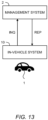
- FIG. 1 is a conceptual diagram for explaining an overview of a vehicle 1 according to the present embodiment.
- the vehicle 1 has a function of operating in accordance with a remote instruction INS.
- the vehicle 1 has a function of operating in accordance with the remote instruction INS in a predetermined area AR.
- the predetermined area AR is, for example, an area in which the vehicle 1 is able to travel automatically. In this case, the vehicle 1 automatically travels in the predetermined area AR in accordance with the remote instruction INS.
- the predetermined area AR may be an area in which a service utilizing the vehicle 1 is provided. In this case, the vehicle 1 provides the service in the predetermined area AR in accordance with the remote instruction INS.
- Various examples of the predetermined area AR will be described later.
- the remote instruction INS instructs to power on or off the vehicle 1, for example.
- Powering on the vehicle 1 means bringing the vehicle 1 into an operable state.
- the powering on the vehicle 1 includes starting power supply to various devices installed on the vehicle 1.
- the powering on the vehicle 1 may include turning on ignition of the vehicle 1.
- powering off the vehicle 1 means bringing the vehicle 1 into an inoperable state.
- the powering off the vehicle 1 includes turning off the ignition of the vehicle 1.
- the powering off the vehicle 1 may include stopping power supply to various devices installed on the vehicle 1. It should be noted that at least a function of receiving the remote instruction INS is activated even after the vehicle 1 is powered off. Therefore, even after the power-off, the vehicle 1 can receive a remote instruction INS instructing the power-on and automatically power on in accordance with the remote instruction INS.
- the remote instruction INS may instruct to perform at least one of steering, acceleration, and deceleration of the vehicle 1.
- the remote instruction INS may instruct to perform autonomous travel of the vehicle 1.
- the remote instruction INS may instruct to recognize a situation around the vehicle 1 using a recognition sensor installed on the vehicle 1.
- the remote instruction INS may instruct to lock or unlock a door of the vehicle 1.
- the remote instruction INS is generated by a management system 2.
- the management system 2 manages at least the vehicle 1 in the predetermined area AR.
- the management system 2 may manage the predetermined area AR.
- the management system 2 may manage the service provided by utilizing the vehicle 1 in the predetermined area AR.
- the vehicle 1 and the management system 2 can communicate with each other.
- the management system 2 transmits the remote instruction INS to the vehicle 1 in the predetermined area AR, as necessary.
- the vehicle 1 in the predetermined area AR receives the remote instruction INS transmitted from the management system 2 and operates in accordance with the received remote instruction INS.
- the management system 2 is realized by, for example, a management server on a cloud.
- the management system 2 may be configured by multiple servers that perform distributed processing.
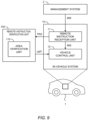
- FIG. 2 is a block diagram for explaining an overview of an in-vehicle system 10 installed on the vehicle 1.
- the in-vehicle system 10 includes a remote instruction reception unit 11 and a vehicle control unit 12.
- the remote instruction reception unit 11 receives the remote instruction INS transmitted from the management system 2. It should be noted that even after the vehicle 1 is powered off, the remote instruction reception unit 11 is activated and stands by for the remote instruction INS transmitted from the management system 2.
- the vehicle control unit 12 controls the vehicle 1.
- the controlling the vehicle 1 includes powering on or off the vehicle 1.
- the controlling the vehicle 1 includes controlling travel (steering, acceleration, and deceleration) of the vehicle 1.
- the controlling the vehicle 1 may include automated driving control of the vehicle 1.
- the controlling the vehicle 1 may include recognizing a situation around the vehicle 1 by using a recognition sensor installed on the vehicle 1.
- the controlling the vehicle 1 may include locking or unlocking a door of the vehicle 1.
- the controlling the vehicle 1 may include turning on or off a light (e.g., a headlight, a hazard lamp) of the vehicle 1.
- the controlling the vehicle 1 may include blowing a horn of the vehicle 1.
- the vehicle control unit 12 controls the vehicle 1 in accordance with the received remote instruction.
- FIG. 3 is a conceptual diagram for explaining automated valet parking (AVP).
- the predetermined area AR is a parking lot.
- the parking lot may be indoor or may be outdoor.
- a plurality of landmarks (markers) M are arranged in the parking lot. Identification information is given to each landmark M.
- An AVP vehicle 1A is the vehicle 1 that supports the automated valet parking in the parking lot.
- the AVP vehicle 1A is able to automatically travel at least in the parking lot. More specifically, the AVP vehicle 1A is provided with a recognition sensor (e.g., a camera) for recognizing a surrounding situation.
- the AVP vehicle 1A automatically travels in the parking lot while recognizing the surrounding situation by using the recognition sensor.
- the AVP vehicle 1A uses a camera to acquire an image indicating a situation around the AVP vehicle 1A, and recognizes the landmark M based on the image.
- the AVP vehicle 1A is able to recognize an entry area based on a result of recognition of the landmark M.
- the AVP vehicle 1A performs "localization process (self-position estimation process, localization)" that estimates a position of the AVP vehicle 1A in the parking lot with high accuracy on the basis of the result of recognition of the landmark M. More specifically, the AVP vehicle 1A estimates its position with high accuracy by combining the result of recognition of the landmark M based on the camera and map information of the landmarks M in the parking lot.
- a target path PT is a path of movement from the entry area to a target parking space allocated to the AVP vehicle 1A. Based on the position of the AVP vehicle 1A estimated by the localization process and the target path PT, the AVP vehicle 1A performs autonomous travel so as to follow the target path PT. This enables the AVP vehicle 1A to automatically move from the entry area to the target parking space.
- the management system 2 manages the automated valet parking in the parking lot.
- the management system 2 is capable of communicating with vehicles including the AVP vehicle 1A in the parking lot.
- the management system 2 issues the remote instruction INS to the AVP vehicle 1A.
- the remote instruction INS instructs to power on or off the AVP vehicle 1A.
- the remote instruction INS instructs to start the autonomous travel.
- the management system 2 may provide the AVP vehicle 1A with map information of the landmarks M in the parking lot.
- the management system 2 may allocate a parking space to the AVP vehicle 1A.
- the management system 2 may generate the target path PT from the entry area to the allocated parking space and provide the AVP vehicle 1A with information on the target path PT.
- the management system 2 may grasp respective positions of the vehicles including the AVP vehicle 1A in the parking lot.
- the management system 2 may remotely operate the AVP vehicle 1A in the parking lot.
- the management system 2 may include a vehicle management center 2A and a parking lot control center 2B.
- the parking lot control center 2B is installed for each parking lot.
- the parking lot control center 2B grasps a situation of the parking lot, allocates a parking space to the AVP vehicle 1A, generates the target path PT, provides the AVP vehicle 1A with the information on the target path PT, and so forth.
- the vehicle management center 2A controls parking lot control centers 2B of a large number of parking lots. For that purpose, the vehicle management center 2A communicates with each parking lot control center 2B to collect a variety of information and provide a variety of information. In addition, the vehicle management center 2A manages the AVP vehicle 1A, and transmits the remote instruction INS to the AVP vehicle 1A as necessary. Furthermore, the vehicle management center 2A manages users and reservations of an automated valet parking service. The vehicle management center 2A may communicate with a user terminal 3 operated by a user of the automated valet parking service.
- the user makes a reservation of the automated valet parking service.
- the user operates the user terminal 3 to input ID information of the user, a desired parking lot, a desired date of use, a desired time of use (i.e., a desired entry time and a desired exit time), and the like.
- the user terminal 3 sends reservation information including the input information to the vehicle management center 2A.
- the vehicle management center 2A executes reservation processing based on the reservation information, and sends a reservation completion notification to the user terminal 3.
- the vehicle management center 2A sends authentication information associated with the reservation information to the user terminal 3.
- the user terminal 3 receives the authentication information and holds the received authentication information.
- Entry (check-in) of the AVP vehicle 1A into the parking lot is as follows.
- the AVP vehicle 1A with the user arrives and stops at the entry area (drop-off area) of the parking lot.
- the user gets off the AVP vehicle 1A.
- the user requests the entry of the AVP vehicle 1A by using the authentication information held in the user terminal 3.
- the vehicle management center 2A conducts authentication of the user.
- authority to operate the AVP vehicle 1A is transferred from the user to the vehicle management center 2A.
- the vehicle management center 2A executes entry processing with regard to the AVP vehicle 1A.
- the vehicle management center 2A communicates with the AVP vehicle 1A to transmit the remote instruction INS that instructs to power on the AVP vehicle 1A.
- the AVP vehicle 1A is automatically powered on in accordance with the received remote instruction INS.
- the parking lot control center 2B refers to a utilization status of the parking lot to allocate an available parking space to the AVP vehicle 1A. Then, the parking lot control center 2B communicates with the AVP vehicle 1A to transmit, as the remote instruction INS, an entry instruction that instructs the AVP vehicle 1A to start the autonomous travel.
- the entry instruction includes information of the target parking space allocated to the AVP vehicle 1A and map information of the parking lot.
- the entry instruction may include information on the target path PT from the entry area to the target parking space.
- the AVP vehicle 1A In response to the entry instruction, the AVP vehicle 1A starts the autonomous travel.
- the AVP vehicle 1A automatically travels from the entry area to the target parking space and automatically parks in the target parking space.
- the AVP vehicle 1A may travel along the target path PT specified by the parking lot control center 2B.
- the parking lot control center 2B may communicate with the AVP vehicle 1A to remotely control the autonomous travel of the AVP vehicle 1A.
- the AVP vehicle 1A Upon completion of the parking, the AVP vehicle 1A notifies the vehicle management center 2A of the parking completion.
- the parking lot control center 2B may use an infrastructure sensor installed in the parking lot to detect completion of the parking of the AVP vehicle 1A and notify the vehicle management center 2A of the parking completion.
- the vehicle management center 2A communicates with the AVP vehicle 1A to transmit the remote instruction INS that instructs to power off the AVP vehicle 1A.
- the AVP vehicle 1A is automatically powered off in accordance with the received remote instruction INS.
- Exit (check-out) of the AVP vehicle 1A from the parking lot is as follows.
- the user uses the user terminal 3 to request exit of the AVP vehicle 1A.
- the exit request includes authentication information.
- the exit request may include information of an exit area (pick-up area) specified by the user.
- the vehicle management center 2A conducts authentication of the user.
- the vehicle management center 2A executes exit processing with regard to the AVP vehicle 1A.
- the vehicle management center 2A communicates with the AVP vehicle 1A to transmit the remote instruction INS that instructs to power on the AVP vehicle 1A.
- the AVP vehicle 1A is automatically powered on in accordance with the received remote instruction INS.
- the parking lot control center 2B communicates with the AVP vehicle 1A to transmit, as the remote instruction INS, an exit instruction that instructs the AVP vehicle 1A to start the autonomous travel.
- the exit instruction includes information of the exit area (pick-up area) and map information of the parking lot.
- the exit instruction may include information on the target path PT from the parking space to the exit area (pick-up area).
- the AVP vehicle 1A In response to the exit instruction, the AVP vehicle 1A starts the autonomous travel.
- the AVP vehicle 1A automatically travels from parking space to the exit area.
- the AVP vehicle 1A may travel along the target path PT specified by the parking lot control center 2B.
- the parking lot control center 2B may communicate with the AVP vehicle 1A to remotely control the autonomous travel of the AVP vehicle 1A.
- the AVP vehicle 1A arrives and stops at the exit area.
- the authority to operate the AVP vehicle 1A is transferred from the vehicle management center 2A to the user.
- the user (and other occupants if any) gets on the AVP vehicle 1A.
- the AVP vehicle 1A departs to a next destination.
- the AVP vehicle 1A receives the remote instruction INS instructing to power on from the management system 2.
- the AVP vehicle 1A is automatically powered on in accordance with the received remote instruction INS and then starts the autonomous travel in the parking lot.
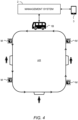
- FIG. 4 is a conceptual diagram for explaining a mobility service in the predetermined area AR.
- the predetermined area AR is an area in which the mobility service is provided.
- the predetermined area AR is a city such as a "smart city" or a part of the city.
- a mobility service vehicle 1B is the vehicle 1 for providing the mobility service in the predetermined area AR.
- Examples of the mobility service vehicle 1B include a bus, a taxi, a shared car, and the like.
- Examples of the bus include a route bus, a sightseeing bus, an on-demand bus, a semi-demand bus, and the like.
- the mobility service vehicle 1B performs autonomous travel (autonomous driving) in the predetermined area AR. More specifically, the mobility service vehicle 1B is provided with a recognition sensor (for example, a camera) for recognizing a surrounding situation. The mobility service vehicle 1B performs the autonomous travel in the predetermined area AR while recognizing the surrounding situation using the recognition sensor.
- a recognition sensor for example, a camera
- Landmarks (markers) M used for the localization process may be arranged in the predetermined area AR.
- the mobility service vehicle 1B uses a camera to acquire an image indicating a situation around the mobility service vehicle 1B and recognizes the landmark M based on the acquired image.
- the mobility service vehicle 1B performs the localization process based on a result of recognition of the landmark M to estimate the self-position in the predetermined area AR.
- the mobility service vehicle 1B performs the autonomous travel based on the estimated self-position.
- the management system 2 manages the mobility service and each mobility service vehicle 1B in the predetermined area AR.
- the management system 2 is capable of communicating with each mobility service vehicle 1B in the predetermined area AR.
- the management system 2 communicates with each mobility service vehicle 1B to collect information on a position and a state of each mobility service vehicle 1B.
- the management system 2 issues the remote instruction INS to the mobility service vehicle 1B, as necessary.
- the remote instruction INS instructs to power on or off the mobility service vehicle 1B.
- the remote instruction INS may remotely instruct the mobility service vehicle 1B to perform at least one of steering, acceleration, and deceleration.
- the management system 2 manages users and reservations of the mobility service.
- the management system 2 may communicate with a user terminal 3 operated by a user of the mobility service.
- the vehicle 1 may be a robot that autonomously travel in the predetermined area AR.
- the vehicle 1 is a logistics robot that automatically transports a package in the predetermined area AR such as a city, a warehouse, a factory, and the like.
- the vehicle 1 may be a work robot that performs predetermined work in the predetermined area AR such as a warehouse, a factory, and the like.
- the vehicle 1 has the function of operating in accordance with the remote instruction INS in the predetermined area AR. Such the function is useful in providing services using the vehicle 1.
- the vehicle 1 since the vehicle 1 has the function of operating in accordance with the remote instruction INS, there is a possibility that the function is abused. That is, there is a possibility that someone with malicious intent fakes a remote instruction INS and issues the fake remote instruction INS to operate (hijack) the vehicle 1 without permission.
- the remote instruction INS faked will be hereinafter referred to as a "fake remote instruction INS-F.”
- a person who maliciously issues the fake remote instruction INS-F to the vehicle 1 is hereinafter referred to as a "fake remote instruction issuer X.”
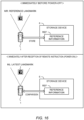
- FIG. 5 shows a case where the vehicle 1 is outside the predetermined area AR.
- the management system 2 transmits the remote instruction INS to the vehicle 1 when the vehicle 1 is within the predetermined area AR.
- the management system 2 does not transmit the remote instruction INS to the vehicle 1.
- the AVP vehicle 1A (see FIG. 3 ) supporting the automated valet parking operates in accordance with the remote instruction INS in the parking lot, but is driven by a user outside the parking lot. Outside the parking lot, the AVP vehicle 1A never receives the remote instruction INS from the management system 2.
- the fake remote instruction issuer X may issue the fake remote instruction INS-F to the vehicle 1 located outside the predetermined area AR.
- the fake remote instruction issuer X can operate (hijack) the vehicle 1 without permission by giving the fake remote instruction INS-F.
- the fake remote instruction issuer X powers on the AVP vehicle 1A (see FIG. 3 ) located outside the parking lot, unlocks its door, and steals the AVP vehicle 1A.
- the fake remote instruction issuer X hijacks the AVP vehicle 1A located outside a parking lot and makes the AVP vehicle 1A automatically travel outside the parking lot to cause an accident.
- FIG. 6 shows a case where the vehicle 1 is in the predetermined area AR.
- the fake remote instruction issuer X can operate (hijack) the vehicle 1 in the predetermined area AR without permission by giving the fake remote instruction INS-F.
- the fake remote instruction issuer X powers on the mobility service vehicle 1B (see FIG. 4 ) waiting in a waiting area, unlocks its door, and steals the mobility service vehicle 1B.
- the fake remote instruction issuer X hijacks the mobility service vehicle 1B in service and causes an accident.
- the fake remote instruction issuer X powers on the AVP vehicle 1A (see FIG. 3 ) located within a parking lot and makes the AVP vehicle 1A automatically travel in the parking lot to cause an accident.
- the present embodiment provides a technique capable of suppressing the abuse of the function of the vehicle 1 that operates in accordance with the remote instruction INS in the predetermined area AR.
- verifying when the vehicle 1 receives a remote instruction INS (this may be a fake remote instruction INS-F), verification (validation) of the received remote instruction INS is performed.
- Verifying the remote instruction INS means determining whether or not the remote instruction INS is valid.
- verifying the remote instruction INS means determining whether the remote instruction INS is a valid remote instruction INS transmitted from the management system 2 or a fake remote instruction INS-F.
- the process of verifying the remote instruction INS received by the vehicle 1 is hereinafter referred to as a "remote instruction verification process.”
- FIG. 7 is a block diagram for explaining an overview of the remote instruction verification process according to the present embodiment.
- a remote instruction verification unit 100 performs the remote instruction verification process.
- the remote instruction verification unit 100 is included in the in-vehicle system 10 of the vehicle 1.
- the remote instruction verification unit 100 may be included in the management system 2.
- the remote instruction verification unit 100 may be distributed to the in-vehicle system 10 and the management system 2.
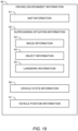
- FIG. 8 is a flowchart showing processing related to the remote instruction verification process according to the present embodiment.
- Step S10 the remote instruction reception unit 11 of the in-vehicle system 10 receives a remote instruction INS (this may be a fake remote instruction INS-F). Upon receiving the remote instruction INS, the remote instruction reception unit 11 transmits a trigger signal TRG to the remote instruction verification unit 100. Thereafter, the processing proceeds to Step S100.
- a remote instruction INS this may be a fake remote instruction INS-F.
- the vehicle control unit 12 may temporarily power on the vehicle 1. In this case, the vehicle control unit 12 waits without performing other processing until a result of the remote instruction verification process is available.
- Step S100 the remote instruction verification unit 100 receives the trigger signal TRG.
- the remote instruction verification unit 100 performs the remote instruction verification process that determines whether or not the remote instruction INS received by the in-vehicle system 10 is valid.
- the remote instruction verification process determines whether or not the remote instruction INS received by the in-vehicle system 10 is valid.
- Various examples can be considered as a concrete method of the remote instruction verification process.
- Various examples of the remote instruction verification processes will be described later.
- Step S100 When the remote instruction INS received by the in-vehicle system 10 is valid (Step S100; Yes), the processing proceeds to Step S200.
- Step S200 the remote instruction verification unit 100 notifies the vehicle control unit 12 of the in-vehicle system 10 of the fact that the remote instruction INS is valid.
- the vehicle control unit 12 controls the vehicle 1 in accordance with the received remote instruction INS as usual.
- Step S100 when it is determined that the received remote instruction INS is the fake remote instruction INS-F (Step S100; No), the processing proceeds to Step S300.
- Step S300 the remote instruction verification unit 100 performs an "operation limiting process.”
- the operation limiting process is a process of limiting at least a part of the operation of the vehicle 1 without following the received remote instruction INS. More specifically, the remote instruction verification unit 100 transmits an operation limiting signal LMT to the vehicle control unit 12.
- the operation limiting signal LMT instructs to limit at least a part of the operation of the vehicle 1 without following the received remote instruction INS.
- the operation limiting signal LMT may include a content of the operation of the vehicle 1 to be limited.
- the vehicle control unit 12 limits at least a part of the operation of vehicle 1 in accordance with the operation limiting signal LMT. Examples of the operation limiting process are as follows.
- a first example of the operation limiting process is to power off the vehicle 1.
- the vehicle control unit 12 temporarily powers on the vehicle 1. After that, when receiving the operation limiting signal LMT instructing to power off, the vehicle control unit 12 immediately powers off the vehicle 1 to make the vehicle 1 inoperable. This can prevent theft of the vehicle 1 and accident occurrence.
- a second example of the operation limiting process is to prohibit movement (travel) of the vehicle 1. Even if the fake remote instruction INS-F instructs to perform the autonomous travel the vehicle 1, the vehicle control unit 12 does not move the vehicle 1 at all. This can prevent theft of the vehicle 1 and accident occurrence. It should be noted that power supply to various devices mounted on the vehicle 1 may be continued while the movement of the vehicle 1 is prohibited.
- a third example of the operation limiting process is to issue an alarm from the vehicle 1 while prohibiting the movement (travel) of the vehicle 1.
- the vehicle control unit 12 turns on or blinks lights (e.g., a headlight, a hazard lamp) of the vehicle 1.
- the vehicle control unit 12 may blow a horn of the vehicle 1.
- a fourth example of the operation limiting process is to prohibit unlocking of a door of the vehicle 1. As a result, intrusion into the vehicle 1 is prevented.
- a fifth example of the operation limiting process relates to a case where the fake remote instruction INS-F is received when the vehicle 1 is in motion. More specifically, the fifth example of the operation limiting process is to immediately decelerate and stop the vehicle 1. As a result, an occurrence of an accident is suppressed.
- Step S400 the remote instruction verification unit 100 notifies the management system 2 of the anomaly detection.
- the management system 2 notifies the user terminal 3 of the anomaly detection.
- the remote instruction verification process is performed to determine whether or not the remote instruction INS is valid.
- the operation limiting process that limits at least a part of the operation of the vehicle 1 without following the remote instruction INS is performed.
- Step S100 remote instruction verification process
- the management system 2 transmits the remote instruction INS to the vehicle 1 when the vehicle 1 is within the predetermined area AR.
- the management system 2 does not transmit the remote instruction INS to the vehicle 1.
- the AVP vehicle 1A (see FIG. 3 ) supporting the automated valet parking operates in accordance with the remote instruction INS in the parking lot, but is driven by a user outside the parking lot. Outside the parking lot, the AVP vehicle 1A never receives the remote instruction INS from the management system 2. If a remote instruction INS is received when the vehicle 1 is located outside the predetermined area AR, the remote instruction INS is highly likely to be not a valid remote instruction transmitted from the management system 2 but the fake remote instruction INS-F.
- determining whether or not the vehicle 1 is present in the predetermined area AR at a time when the vehicle 1 receives the remote instruction INS is considered.
- a process of determining whether or not the vehicle 1 is present in the predetermined area AR at the time when the vehicle 1 receives the remote instruction INS is hereinafter referred to as an "area verification process.”
- the remote instruction verification unit 100 includes an area verification unit 110.
- the area verification unit 110 performs the area verification process in response to the trigger signal TRG. If the vehicle 1 is not present in the predetermined area AR at the time when the vehicle 1 receives the remote instruction INS, the area verification unit 110 determines that the received remote instruction INS is invalid.
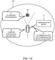
- FIG. 10 is a conceptual diagram for explaining various examples of the area verification process.
- a first example of the area verification process is to determine whether or not a landmark M arranged in the predetermined area AR is recognizable from a position of the vehicle 1.
- the area verification unit 110 determines that the vehicle 1 is not present in the predetermined area AR.
- the vehicle 1 (the in-vehicle system 10) is configured to recognize the landmark M around the vehicle 1 by using a recognition sensor such as a camera and the like mounted on the vehicle 1.
- the area verification unit 110 included in the in-vehicle system 10 determines whether or not the in-vehicle system 10 recognizes the landmark M around the vehicle 1.
- the area verification unit 110 determines that the landmark M is not recognizable from the position of the vehicle 1. That is, the area verification unit 110 determines that the vehicle 1 is not present in the predetermined area AR.
- the vehicle 1 (the in-vehicle system 10) transmits image information captured by the camera mounted on the vehicle 1 to the management system 2.
- the management system 2 is configured to recognize the landmark M around the vehicle 1 based on the image information received from the vehicle 1.
- the area verification unit 110 included in the management system 2 determines whether or not the management system 2 recognizes the landmark M around the vehicle 1. When the management system 2 does not recognize the landmark M, the area verification unit 110 determines that the landmark M is not recognizable from the position of the vehicle 1. That is, the area verification unit 110 determines that the vehicle 1 is not present in the predetermined area AR.
- a second example of the area verification process is to compare the position information of the vehicle 1 with map information.
- a position of the predetermined area AR is registered in the map information. Therefore, comparing the position information of the vehicle 1 with the map information makes it possible to determine whether or not the vehicle 1 is present in the predetermined area AR.
- the in-vehicle system 10 acquires the position information of the vehicle 1 by using a position sensor such as a GPS and the like.
- the in-vehicle system 10 acquires the position information of the vehicle 1 by performing the localization process.
- the area verification unit 110 included in the in-vehicle system 10 acquires the position information of the vehicle 1 and compares the position information of the vehicle 1 with the map information to determine whether or not the vehicle 1 is present in the predetermined area AR.
- the in-vehicle system 10 transmits the position information of the vehicle 1 to the management system 2.
- the management system 2 acquires the position information of the vehicle 1 from the in-vehicle system 10.
- the area verification unit 110 included in the management system 2 acquires the position information of the vehicle 1 and compares the position information of the vehicle 1 with the map information to determine whether or not the vehicle 1 is present in the predetermined area AR.
- the vehicle 1 (the in-vehicle system 10) and a communication device 5 installed in the predetermined area AR are configured to communicate with each other in accordance with a specific communication scheme.
- the parking lot control center 2B corresponds to the communication device 5, and the AVP vehicle 1A in the parking lot and the parking lot control center 2B communicate with each other in accordance with a specific communication scheme.
- the specific communication scheme is a short-range wireless communication scheme such as WiFi (registered trademark), Bluetooth (registered trademark), and the like.
- a third example of the area verification process is to determine whether or not a communication is established between the vehicle 1 (the in-vehicle system 10) and the communication device 5 installed in the predetermined area AR.
- the area verification unit 110 determines that the vehicle 1 is not present in the predetermined area AR.
- the area verification unit 110 may be included in the in-vehicle system 10 or may be included in the communication device 5 included in the management system 2.
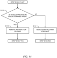
- FIG. 11 is a flowchart summarizing the area verification process performed by the area verification unit 110.
- the area verification unit 110 may be included in the in-vehicle system 10 or may be included in the management system 2. Alternatively, the area verification unit 110 may be distributed to the in-vehicle system 10 and the management system 2.
- Step S110 the area verification unit 110 determines whether or not the vehicle 1 is present in the predetermined area AR.
- the area verification unit 110 determines that the received remote instruction INS is valid (Step Sill).
- the area verification unit 110 determines that the received remote instruction INS is invalid (Step S112).
- checking (confirming) whether or not the management system 2 has actually transmitted the remote instruction INS to the vehicle 1 is considered.
- a process of checking (confirming) whether or not the management system 2 has actually transmitted the remote instruction INS to the vehicle 1 is hereinafter referred to as a "source verification process.”
- the remote instruction verification unit 100 includes a source verification unit 120.
- the source verification unit 120 performs the source verification process in response to the trigger signal TRG.
- the management system 2 has not actually transmitted the remote instruction INS to the vehicle 1, the source verification unit 120 determines that the received remote instruction INS is invalid.
- FIG. 13 is a conceptual diagram for explaining an example of the source verification process.
- the source verification unit 120 is distributed to the in-vehicle system 10 and the management system 2.
- the source verification unit 120 on the side of the in-vehicle system 10 transmits inquiry information INQ to the management system 2.
- the inquiry information INQ is information for inquiring whether or not the remote instruction INS has been actually transmitted to the vehicle 1.
- the source verification unit 120 on the side of the management system 2 checks whether or not the management system 2 has actually transmitted the remote instruction INS to the vehicle 1 being the inquiry source. Then, the source verification unit 120 on the side of the management system 2 returns reply information REP indicating the check result to the in-vehicle system 10.
- the reply information REP indicates that there is no fact of transmission of the remote instruction INS
- the source verification unit 120 on the side of the in-vehicle system 10 determines that the received remote instruction INS is invalid.
- the source verification unit 120 on the side of the management system 2 may determine that the remote instruction INS is invalid and generate the operation limiting signal LMT.
- the operation limiting signal LMT is included in the reply information REP transmitted from the management system 2 to the in-vehicle system 10.
- the vehicle control unit 12 of the in-vehicle system 10 performs the operation limiting process in accordance with the operation limiting signal LMT.
- FIG. 14 is a flowchart summarizing the source verification process performed by the source verification unit 120.
- the source verification unit 120 is distributed to the in-vehicle system 10 and the management system 2.
- Step S120 the source verification unit 120 on the side of the in-vehicle system 10 transmits the inquiry information INQ to the management system 2.
- Step S121 the source verification unit 120 on the side of the management system 2 checks whether or not the management system 2 has actually transmitted the remote instruction INS to the vehicle 1.
- the management system 2 has actually transmitted the remote instruction INS (Step S121; Yes)
- the source verification unit 120 determines that the received remote instruction INS is valid (Step S122).
- Step S121 when the management system 2 has not actually transmitted the remote instruction INS (Step S121; No)
- the source verification unit 120 determines that the received remote instruction INS is invalid (Step S123).
- the landmarks M are arranged in the predetermined area AR.
- the vehicle 1 (the in-vehicle system 10) recognizes the landmark M around the vehicle 1 by using a recognition sensor such as a camera and the like mounted on the vehicle 1.
- the vehicle 1 (the in-vehicle system 10) transmits image information captured by the camera mounted on the vehicle 1 to the management system 2.
- the management system 2 recognizes the landmark M around the vehicle 1 based on the image information received from the vehicle 1.
- determining whether or not the landmark M itself recognized from the position of the vehicle 1 is valid is considered.
- a process of determining whether or not the landmark M itself recognized from the position of the vehicle 1 is valid is hereinafter referred to as a "recognition result verification process.”
- the remote instruction verification unit 100 includes a recognition result verification unit 130.
- the recognition result verification unit 130 may be included in the in-vehicle system 10 or may be included in the management system 2. Alternatively, the recognition result verification unit 130 may be distributed to the in-vehicle system 10 and the management system 2.
- FIG. 16 is a conceptual diagram for explaining an example of the recognition result verification process.
- the remote instruction INS is one instructing to power on the vehicle 1.
- reference landmark MR is a landmark M recognized from the position of the vehicle 1 immediately before the vehicle 1 is powered off.
- Reference information REF is information corresponding to the reference landmark MR.
- the reference information REF includes identification information of the reference landmark MR.
- the reference information REF may include position information of the reference landmark MR.
- the reference information REF may include a position and an orientation of the vehicle 1 when the reference landmark MR is recognized. The reason is that the reference landmark MR recognizable from the vehicle 1 can be identified based on map information of the landmarks M and the position and the orientation of the vehicle 1.
- the recognition result verification unit 130 acquires the reference information REF and stores the reference information REF in a predetermined storage device 6.
- the predetermined storage device 6 may be installed on the vehicle 1 or may be included in the management system 2.
- the recognition result verification unit 130 included in the in-vehicle system 10 acquires the reference information REF from the in-vehicle system 10 and stores the reference information REF in the predetermined storage device 6 installed on the vehicle 1.
- the recognition result verification unit 130 included in the in-vehicle system 10 may transmit the reference information REF to the management system 2, and the recognition result verification unit 130 included in the management system 2 may store the reference information REF in the predetermined storage device 6 of the management system 2.
- the recognition result verification unit 130 included in the management system 2 may acquire the reference information REF from the management system 2 and store the reference information REF in the predetermined storage device 6 of the management system 2.
- the in-vehicle system 10 receives the remote instruction INS that instructs to power on the vehicle 1.
- the recognition result verification unit 130 performs the recognition result verification process in response to the trigger signal TRG.
- a "latest landmark ML" is a landmark M recognized first from the position of the vehicle 1 after the power-on.
- the recognition result verification unit 130 acquires information on the latest landmark ML from the in-vehicle system 10 or the management system 2.
- the information on the latest landmark ML includes at least one of position information and identification information of the latest landmark ML.
- the recognition result verification unit 130 reads the above-described reference information REF from the predetermined storage device 6.
- the recognition result verification unit 130 acquires the information on the reference landmark MR based on the read reference information REF.
- the information on the reference landmark MR includes at least one of the position information and the identification information of the reference landmark MR.
- the recognition result verification unit 130 determines whether or not the latest landmark ML is consistent with the reference landmark MR. When the latest landmark ML is not consistent with the reference landmark MR, the recognition result verification unit 130 determines that the received remote instruction INS is invalid.
- the recognition result verification unit 130 can judge that the vehicle 1 is unintentionally moved during a period in which the vehicle 1 is powered off. That is, it is possible to detect anomaly occurrence (for example, theft) in the period when the vehicle 1 is powered off.
- FIG. 17 is a flowchart summarizing the recognition result verification process performed by the recognition result verification unit 130.
- the recognition result verification unit 130 may be included in the in-vehicle system 10 or may be included in the management system 2. Alternatively, the recognition result verification unit 130 may be distributed to the in-vehicle system 10 and the management system 2.
- Step S130 the recognition result verification unit 130 acquires the information on the latest landmark ML recognized first from the position of the vehicle 1 after the power-on.
- Step S131 the recognition result verification unit 130 determines whether or not the latest landmark ML is consistent with the reference landmark MR based on the reference information REF.
- the recognition result verification unit 130 determines that the received remote instruction INS is valid (Step S132).
- the recognition result verification unit 130 determines that the received remote instruction INS is invalid (Step S133).
- the remote instruction verification process may include two or more of the area verification process, the source verification process, and the recognition result verification process described above. That is, the remote instruction verification unit 100 may include two or more of the area verification unit 110, the source verification unit 120, and the recognition result verification unit 130. In the remote instruction verification unit 100, two or more of the area verification unit 110, the source verification unit 120, and the recognition result verification unit 130 may operate in parallel or in series. When at least one of the area verification unit 110, the source verification unit 120, and the recognition result verification unit 130 determines that the remote instruction INS is invalid, the remote instruction verification unit 100 determines that the remote instruction INS is invalid.
- the combination of the two or more of the area verification process, the source verification process, and the recognition result verification process further improves the accuracy of the remote instruction verification process.
- the remote instruction verification process is performed to determine whether or not the remote instruction INS is valid.
- the operation limiting process that limits at least a part of the operation of the vehicle 1 without following the remote instruction INS is performed.
- a vehicle control system (a moving body control system) according to the present embodiment includes the remote instruction verification unit 100 described above.
- the remote instruction verification unit 100 is included in the in-vehicle system 10 of the vehicle 1.
- the in-vehicle system 10 of the vehicle 1 corresponds to the vehicle control system.
- the remote instruction verification unit 100 may be included in the management system 2.
- the management system 2 corresponds to the vehicle control system.
- the remote instruction verification unit 100 may be distributed to the in-vehicle system 10 and the management system 2.
- a combination of the management system 2 and the in-vehicle system 10 corresponds to the vehicle control system.
- FIG. 18 is a block diagram showing a configuration example of the in-vehicle system 10 according to the present embodiment.
- the in-vehicle system 10 includes a sensor group 20, a travel device 30, light/horn 40, a communication device 50, and a control device 60.
- the sensor group 20 includes a recognition sensor 21, a vehicle state sensor 22, a position sensor 23, and the like.
- the recognition sensor 21 recognizes (detects) a situation around the vehicle 1.
- the recognition sensor 21 includes a camera C.
- the camera C captures image information indicating a situation around the vehicle 1.
- the recognition sensor 21 may include a laser imaging detection and ranging (LIDAR), a radar, and the like.
- the vehicle state sensor 22 detects a state of the vehicle 1.
- the vehicle state sensor 22 includes a speed sensor (a wheel speed sensor), an acceleration sensor, a yaw rate sensor, a steering angle sensor, and the like.
- the position sensor 23 detects a position and an orientation of the vehicle 1.
- the position sensor 23 is exemplified by a GPS (Global Positioning System) sensor.
- the travel device 30 includes a steering device, a driving device, and a braking device.
- the steering device steers wheels.
- the steering device includes an electric power steering (EPS) device.
- EPS electric power steering
- the driving device is a power source that generates a driving force. Examples of the driving device include an engine, an electric motor, and an in-wheel motor.
- the braking device generates a braking force.
- the light/horn 40 include a light and a horn.
- Examples of the light include a headlight and a hazard lamp.
- the communication device 50 communicates with the outside of the vehicle 1.
- the communication device 50 communicates with the management system 2.
- the communication device 50 communicates with the communication device 5 (see FIG. 10 ) installed in the predetermined area AR.
- the communication with the communication device 5 installed in the predetermined area AR is performed by a specific communication scheme.
- the specific communication scheme is a short-range wireless communication scheme such as WiFi (registered trademark), Bluetooth (registered trademark), and the like.
- the control device 60 is a computer that controls the vehicle 1.
- the control device 60 includes one or more processors 70 (hereinafter, simply referred to as a processor 70) and one or more memory devices 80 (hereinafter, simply referred to as a memory device 80).
- the processor 70 executes a variety of processing.
- the processor 70 includes a central processing unit (CPU).
- the memory device 80 stores a variety of of information. Examples of the memory device 80 include a volatile memory, a nonvolatile memory, a hard disk drive (HDD), a solid state drive (SSD), and the like.
- the control device 60 may include one or more electronic control units (ECUs).
- a vehicle control program PROG is a computer program for controlling the vehicle 1.
- a variety of processing by the control device 60 may be implemented by the processor 70 executing the vehicle control program PROG.
- the vehicle control program PROG is stored in the memory device 80. Alternatively, the vehicle control program PROG may be recorded on a non-transitory computer-readable recording medium.
- the control device 60 acquires driving environment information 90 indicating a driving environment for the vehicle 1.
- the driving environment information 90 is stored in the memory device 80.
- FIG. 19 is a block diagram showing an example of the driving environment information 90.
- the driving environment information 90 includes map information 91, surrounding situation information 92, vehicle state information 96, and vehicle position information 97.
- the map information 91 includes a general navigation map.
- the map information 91 may indicate a lane configuration and a road shape.
- the map information 91 may include position information of structures, traffic signals, signs, and the like. Further, the position of the predetermined area AR (e.g., a parking lot) is registered in the map information 91.
- the map information 91 may include map information in the predetermined area AR.
- the map information 91 may include a position and identification information of each landmark (marker) M arranged in the predetermined area AR.
- the control device 60 acquires the map information 91 from a map database.
- the map database may be stored in the memory device 80 or may be stored in the management system 2. In the latter case, the control device 60 communicates with the management system 2 via the communication device 50 to acquire the necessary map information 91.
- the surrounding situation information 92 is information indicating the situation around the vehicle 1.
- the control device 60 recognizes the situation around the vehicle 1 by using the recognition sensor 21 to acquire the surrounding situation information 92.
- the surrounding situation information 92 includes image information 93 captured by the camera C.
- the surrounding situation information 92 includes point cloud information acquired by the LIDAR.
- the surrounding situation information 92 further includes object information 94 regarding an object around the vehicle 1.
- the object include a pedestrian, a bicycle, a motor bike, another vehicle (a preceding vehicle, a parked vehicle, and the like), the landmark M, a white line, a traffic signal, a sign, a structure, an obstacle, and the like.
- the object information 94 indicates a relative position and a relative speed of an object with respect to the vehicle 1.
- analyzing the image information 93 captured by the camera C makes it possible to identify an object and calculate a relative position of the object.
- the control device 60 identifies an object in the image information 93 by using image recognition AI acquired by machine learning. It is also possible to identify an object and acquire a relative position and a relative speed of the object based on the point group information acquired by the LIDAR.
- landmark information 95 is the object information 94 regarding the landmark M around the vehicle 1.
- the control device 60 recognizes the landmark M around the vehicle 1 by using the recognition sensor 21.
- the control device 60 identifies the landmark M in the image information 93 by using the image recognition AI acquired by machine learning.
- the landmark information 95 includes a relative position of the landmark M with respect to the vehicle 1.
- the landmark information 95 may include identification information of the recognized landmark M.
- the vehicle state information 96 is information indicating the state of the vehicle 1 and includes a vehicle speed (wheel speed), an acceleration, a yaw rate, a steering angle, and the like.
- the control device 60 acquires the vehicle state information 96 from the vehicle state sensor 22.
- the vehicle state information 96 may indicate a driving state (automated driving / manual driving) of the vehicle 1.
- the vehicle position information 97 is information indicating the position and the orientation of the vehicle 1.
- the control device 60 acquires the vehicle position information 97 from a result of detection by the position sensor 23.
- the control device 60 may acquire highly accurate vehicle position information 97 by performing a well-known localization process. More specifically, the control device 60 calculates an amount of movement of the vehicle 1 based on the wheel speed and the steering angle acquired by the vehicle state sensor 22, thereby roughly calculating the vehicle position. Further, the control device 60 corrects the vehicle position by matching the position of the landmark M indicated by the map information 91 and the recognized position of the landmark M indicated by the landmark information 95. Repeating the calculation of the amount of movement and the correction of the vehicle position makes it possible to continuously acquire the highly accurate vehicle position information 97.
- the control device 60 executes "vehicle travel control" that controls travel of the vehicle 1.
- the vehicle travel control includes steering control, acceleration control, and deceleration control.
- the control device 60 executes the vehicle travel control by controlling the travel device 30. More specifically, the control device 60 executes the steering control by controlling the steering device. Further, the control device 60 executes the acceleration control by controlling the driving device. Further, the control device 60 executes the deceleration control by controlling the braking device.
- the control device 60 may execute automated driving control based on the driving environment information 90. More specifically, the control device 60 generates a travel plan of the vehicle 1 based on the driving environment information 90. Examples of the travel plan include keeping a current travel lane, making a lane change, making a right turn or left turn, avoiding an obstacle, and the like. Furthermore, the control device 60 generates a target trajectory required for the vehicle 1 to travel in accordance with the travel plan, based on the driving environment information 90. The target trajectory includes a target position and a target velocity. Then, the control device 60 executes the vehicle travel control such that the vehicle 1 follows the target trajectory.
- the control device 60 controls the light/horn 40. For example, the control device 60 turns on or blinks the light of the vehicle 1. As another example, the control device 60 blows the horn of the vehicle 1.
- the control device 60 communicates with the outside of the vehicle 1 via the communication device 50.
- the control device 60 communicates with the management system 2 via the communication device 50.
- the control device 60 communicates with the communication device 5 (see FIG. 10 ) in the predetermined area AR via the communication device 50.
- the control device 60 receives the remote instruction INS transmitted from the management system 2.
- the control device 60 basically controls the vehicle 1 in accordance with the received remote instruction INS.
- the remote instruction INS instructs to power on or off the vehicle 1.
- the remote instruction INS may instruct to perform the vehicle travel control, that is, at least one of steering, acceleration, and deceleration.
- the remote instruction INS may instruct to execute the automated driving control.
- the remote instruction INS may instruct to recognize a situation around the vehicle 1 using the recognition sensor 21.
- the remote instruction INS may instruct to lock or unlock a door of the vehicle 1.
- the in-vehicle system 10 includes the remote instruction reception unit 11 and the vehicle control unit 12 as functional blocks.
- the remote instruction reception unit 11 is realized by the communication device 50.
- the vehicle control unit 12 is realized by the control device 60.
- the control device 60 may perform the remote instruction verification process described in the above Section 3. That is, the control device 60 may have the function of the remote instruction verification unit 100.
- the control device 60 may perform the area verification process described in the above Section 3-1. That is, the control device 60 may have the function of the area verification unit 110.
- the control device 60 determines whether or not the landmark M is recognizable from the position of the vehicle 1 based on the landmark information 95.
- control device 60 determines whether or not the vehicle 1 is present in the predetermined area AR based on the map information 91 and the vehicle position information 97.
- control device 60 determines whether or not the communication with the communication device 5 installed in the predetermined area AR is established via the communication device 50.
- the control device 60 may perform the source verification process described in the above Section 3-2. That is, the control device 60 may have the function of the source verification unit 120. More specifically, the control device 60 transmits the inquiry information INQ to the management system 2 via the communication device 50. The control device 60 receives the reply information REP from the management system 2 via the communication device 50.
- the control device 60 may perform the recognition result verification process described in the above Section 3-3. That is, the control device 60 may have the function of the recognition result verification unit 130. More specifically, the control device 60 acquires the reference information REF corresponding to the reference landmark MR based on the landmark information 95.
- the reference information REF is stored in, for example, the memory device 80.
- the control device 60 acquires the information on the latest landmark ML based on the landmark information 95. Then, the control device 60 determines whether or not the latest landmark ML is consistent with the reference landmark MR.
- the control device 60 performs the operation limiting process described in the above Section 3. More specifically, the control device 60 generates the operation limiting signal LMT according to the result of the remote instruction verification process. Then, the control device 60 limits at least a part of the operation of the vehicle 1 based on the operation limiting signal LMT without following the remote instruction INS.
- FIG. 20 is a block diagram showing a configuration example of the management system 2 according to the present embodiment.
- the management system 2 includes a communication device 210, one or more processors 220 (hereinafter, simply referred to as a processor 220), and one or more memory devices 230 (hereinafter, simply referred to as a memory device 230).
- the communication device 210 communicates with the outside via a communication network.
- the communication device 210 communicates with the in-vehicle system 10 of the vehicle 1.
- the communication device 210 may include the communication device 5 (see FIG. 10 ) installed in the predetermined area AR.
- the communication device 5 installed in the predetermined area AR communicates with the in-vehicle system 10 of the vehicle 1 by a specific communication scheme.
- the specific communication scheme is a short-range wireless communication scheme such as WiFi (registered trademark), Bluetooth (registered trademark), and the like.
- the processor 220 executes a variety of processing.
- the processor 220 includes a CPU.
- the memory device 230 stores a variety of information. Examples of the memory device 230 include a volatile memory, a nonvolatile memory, an HDD, an SSD, and the like.
- a management program 240 is a computer program executed by the processor 220. Functions of the management system 2 may be implemented by the processor 220 executing the management program 240.
- the management program 240 is stored in the memory device 230. Alternatively, the management program 240 may be recorded on a non-transitory computer-readable recording medium.
- the management program 240 may be provided via a network.
- Map information 250 is similar to the map information 91 described above.
- the map information 250 includes a general navigation map.
- the map information 250 may indicate a lane configuration and a road shape.
- the map information 250 may include position information of structures, traffic signals, signs, and the like. Further, the position of the predetermined area AR (e.g., a parking lot) is registered in the map information 250.
- the map information 250 may include map information in the predetermined area AR.
- the map information 250 may include a position and identification information of each landmark (marker) M arranged in the predetermined area AR.
- the map information 250 is stored in advance in the memory device 230.
- Vehicle information 260 is information transmitted from the in-vehicle system 10 of the vehicle 1.
- the vehicle information 260 includes the image information 93 captured by the camera C mounted on the vehicle 1.
- the vehicle information 260 may include the landmark information 95 regarding the landmark M recognized by the recognition sensor 21.
- the vehicle information 260 may include the vehicle position information 97 indicating the position of the vehicle 1.
- the processor 220 acquires the vehicle information 260 from the in-vehicle system 10 via the communication device 210 and stores the acquired vehicle information 260 in the memory device 230.
- Management information 270 is information used for management by the management system 2.
- the management information 270 includes service information regarding a service managed by the management system 2.
- the service information includes, for example, a usage status of the service.
- the management information 270 may include user information regarding users of the service.
- the processor 220 can recognize the landmark M around the vehicle 1 based on the image information 93 included in the vehicle information 260.
- the processor 220 generates the remote instruction INS for the vehicle 1, as necessary.
- the processor 220 communicates with the in-vehicle system 10 via the communication device 210 to transmit the remote instruction INS to the in-vehicle system 10.
- the remote instruction INS instructing the power ON is transmitted to the in-vehicle system 10.
- the processor 220 may perform the remote instruction verification process described in the above Section 3. That is, the processor 220 may have the function of the remote instruction verification unit 100.
- the processor 220 may perform the area verification process described in the above Section 3-1. That is, the processor 220 may have the function of the area verification unit 110.
- the processor 220 determines whether or not the landmark M is recognizable from the position of the vehicle information 1 based on the image information 93 or the landmark information 95 included in the vehicle information 260.
- the processor 220 determines whether or not the vehicle 1 is present in the predetermined area AR based on the map information 250 and the vehicle position information 97 included in the vehicle information 260.
- the processor 220 determines whether or not the communication with the in-vehicle system 10 of the vehicle 1 is established via the communication device 210 (the communication device 5 installed in the predetermined area AR).
- the processor 220 may perform the source verification process described in the above Section 3-2. That is, the processor 220 may have the function of the source verification unit 120. More specifically, the processor 220 receives the inquiry information INQ from the in-vehicle system 10 via the communication device 210. The processor 220 checks whether or not it has actually transmitted the remote instruction INS to the vehicle 1. Then, the processor 220 returns the reply information REP indicating the check result to the in-vehicle system 10 via the communication device 210.
- the processor 220 may perform the recognition result verification process described in the above Section 3-3. That is, the processor 220 may have the function of the recognition result verification unit 130. More specifically, the processor 220 acquires the reference information REF corresponding to the reference landmark MR based on the image information 93 or the landmark information 95 included in the vehicle information 260.
- the reference information REF is stored in, for example, the memory device 230.
- the processor 220 acquires information regarding the latest landmark ML on the basis of the image information 93 or the landmark information 95 included in the vehicle information 260. Then, the processor 220 determines whether or not the latest landmark ML is consistent with the reference landmark MR.
- the processor 220 may perform the operation limiting process described in the above Section 3. More specifically, the processor 220 generates the operation limiting signal LMT according to the result of the remote instruction verification process. The processor 220 transmits the operation limiting signal LMT to the in-vehicle system 10 via the communication device 210. Transmitting the operation limiting signal LMT to the in-vehicle system 10 makes it possible to indirectly limit the operation of the vehicle 1.
- the automated valet parking shown in FIG. 3 is considered.
- the management system 2 may transmit a test remote instruction INS-T to the AVP vehicle 1A.
- the test remote instruction INS-T instructs to power on the parked AVP vehicle 1A.
- the management system 2 regularly transmits the test remote instruction INS-T.
- the management system 2 may transmit the test remote instruction INS-T a predetermined time before a reserved exit time.
- the remote instruction verification unit 100 performs the remote instruction verification process described in Section 3. If any anomaly is detected, the remote instruction verification unit 100 notifies the management system 2 of the anomaly detection (Step S400 in FIG. 8 ). This makes it possible to voluntarily detect the anomaly occurrence in the AVP vehicle 1A.
- the management system 2 determines that the parked AVP vehicle 1A is normal. In this case, the management system 2 transmits a remote instruction INS instructing power-off to the AVP vehicle 1A.
- transmitting the test remote instruction INS-T makes it possible to check the status of the parked AVP vehicle 1A.
Landscapes
- Engineering & Computer Science (AREA)
- Radar, Positioning & Navigation (AREA)
- Physics & Mathematics (AREA)
- General Physics & Mathematics (AREA)
- Remote Sensing (AREA)
- Automation & Control Theory (AREA)
- Aviation & Aerospace Engineering (AREA)
- Computer Networks & Wireless Communication (AREA)
- Signal Processing (AREA)
- Mechanical Engineering (AREA)
- Transportation (AREA)
- Electromagnetism (AREA)
- Chemical & Material Sciences (AREA)
- Computer Security & Cryptography (AREA)
- Combustion & Propulsion (AREA)
- Traffic Control Systems (AREA)
Abstract
A moving body control method controls a moving body (1) having a function of operating in accordance with a remote instruction (INS) in a predetermined area (AR). The moving body control method includes: a remote instruction verification process that determines whether the remote instruction (INS) received by the moving body (1) is valid; and an operation limiting process that limits at least a part of an operation of the moving body (1) without following the remote instruction (INS), when the remote instruction (INS) received by the moving body (1) is invalid. The remote instruction verification process includes: determining whether or not the moving body (1) is present in the predetermined area (AR) at a time when the moving body (1) receives the remote instruction (INS); and determining that the remote instruction (INS) is invalid, when the moving body (1) is not present in the predetermined area (AR) at the time when the moving body (1) receives the remote instruction (INS).
Description
- The present disclosure relates to a technique for controlling a moving body having a function of operating in accordance with a remote instruction in a predetermined area.
-
Patent Literature 1 discloses a control device used in a parking lot for automated valet parking. A vehicle reads a marker placed in the parking lot and estimates an absolute position of the vehicle based on a relative distance between the vehicle and the marker. On the other hand, the control device acquires information on the vehicle position measured by a sensor installed in the parking lot. The control device compares a static estimation accuracy, which is a difference between the estimated vehicle position and the measured vehicle position, with a reference value. When the static estimation accuracy is equal to or less than the reference value, the control device prevents the vehicle from using an automated valet parking function. - Patent Literature 1: International Publication No.
WO2021/166620 - A moving body (e.g., a vehicle, or a robot) having a function of operating in accordance with a remote instruction in a predetermined area will be considered. For example, when a vehicle supporting automated valet parking enters a parking lot (a predetermined area) or exits the parking lot, the vehicle receives a remote instruction instructing power-on from a management system. The vehicle is automatically powered on in accordance with the received remote instruction and then starts automated travel in the parking lot.
- Controlling the operation of the moving body through the remote instruction is useful in providing services using the moving body, and the like. However, since the moving body has the function of operating in accordance with the remote instruction, there is a possibility that the function is abused. That is, there is a possibility that someone with malicious intent fakes a remote instruction and issues the fake remote instruction to operate (hijack) the moving body without permission. For example, it is conceivable that someone with malicious intent powers on the moving body, unlocks its door, and steals the moving body. As another example, it is also conceivable that someone with malicious intent powers on the moving body and makes the moving body automatically travel to cause an accident.
- An object of the present disclosure is to provide a technique capable of suppressing abuse of a function of a moving body that operates in accordance with a remote instruction in a predetermined area.
- A first aspect is directed to a moving body control method for controlling a moving body having a function of operating in accordance with a remote instruction in a predetermined area.
- The moving body control method includes:
- a remote instruction verification process that determines whether or not the remote instruction received by the moving body is valid; and
- an operation limiting process that limits at least a part of an operation of the moving body without following the remote instruction, when the remote instruction received by the moving body is invalid.
- The remote instruction verification process includes:
- determining whether or not the moving body is present in the predetermined area at a time when the moving body receives the remote instruction; and
- determining that the remote instruction is invalid, when the moving body is not present in the predetermined area at the time when the moving body receives the remote instruction.
- A second aspect is directed to a moving body control system for controlling a moving body having a function of operating in accordance with a remote instruction in a predetermined area.
- The moving body control system includes one or more processors.
- The one or more processors are configured to execute:
- a remote instruction verification process that determines whether or not the remote instruction received by the moving body is valid; and
- an operation limiting process that limits at least a part of an operation of the moving body without following the remote instruction, when the remote instruction received by the moving body is invalid.
- The remote instruction verification process includes:
- determining whether or not the moving body is present in the predetermined area at a time when the moving body receives the remote instruction; and
- determining that the remote instruction is invalid, when the moving body is not present in the predetermined area at the time when the moving body receives the remote instruction.
- A third aspect is directed to a moving body control program for controlling a moving body having a function of operating in accordance with a remote instruction in a predetermined area.
- The moving body control program, when executed by a computer, causes the computer to execute:
- a remote instruction verification process that determines whether or not the remote instruction received by the moving body is valid; and
- an operation limiting process that limits at least a part of an operation of the moving body without following the remote instruction, when the remote instruction received by the moving body is invalid.
- The remote instruction verification process includes:
- determining whether or not the moving body is present in the predetermined area at a time when the moving body receives the remote instruction; and
- determining that the remote instruction is invalid, when the moving body is not present in the predetermined area at the time when the moving body receives the remote instruction.
- According to the present disclosure, when the moving body receives the remote instruction, the remote instruction verification process is performed to determine whether or not the remote instruction is valid. When the remote instruction received by the moving body is invalid, the operation limiting process that limits at least a part of the operation of the moving body without following the remote instruction is performed. As a result, the abuse of the function of the moving body that operates in accordance with the remote instruction is suppressed.
-
-
FIG. 1 is a conceptual diagram for explaining an overview of a vehicle according to an embodiment; -
FIG. 2 is a block diagram for explaining an overview of an in-vehicle system according to an embodiment; -
FIG. 3 is a conceptual diagram for explaining automated valet parking; -
FIG. 4 is a conceptual diagram for explaining a mobility service; -
FIG. 5 is a conceptual diagram for explaining a first problem; -
FIG. 6 is a conceptual diagram for explaining a second problem; -
FIG. 7 is a block diagram for explaining an overview of a remote instruction verification process according to an embodiment; -
FIG. 8 is a flowchart showing processing related to a remote instruction verification process according to an embodiment; -
FIG. 9 is a block diagram for explaining an area verification unit that performs an area verification process according to an embodiment; -
FIG. 10 is a conceptual diagram for explaining various examples of an area verification process according to an embodiment; -
FIG. 11 is a flowchart summarizing an area verification process according to an embodiment; -
FIG. 12 is a block diagram for explaining a source verification unit that performs a source verification process according to an embodiment; -
FIG. 13 is a conceptual diagram for explaining an example of a source verification process according to an embodiment; -
FIG. 14 is a flowchart summarizing a source verification process according to an embodiment; -
FIG. 15 is a block diagram for explaining a recognition result verification unit that performs a recognition result verification process according to an embodiment; -
FIG. 16 is a conceptual diagram for explaining an example of a recognition result verification process according to an embodiment; -
FIG. 17 is a flowchart summarizing a recognition result verification process according to an embodiment; -
FIG. 18 is a block diagram showing a configuration example of an in-vehicle system according to an embodiment; -
FIG. 19 is a block diagram showing an example of driving environment information according to an embodiment; and -
FIG. 20 is a block diagram showing a configuration example of a management system according to an embodiment. - Embodiments of the present disclosure will be described with reference to the accompanying drawings.
- A moving body having a function of operating in accordance with a remote instruction is considered. Examples of the moving body include a vehicle, a robot, and the like. As an example, a case where the moving body is a vehicle will be considered in the following description. When generalizing, "vehicle" in the following description is replaced with "moving body."
-
FIG. 1 is a conceptual diagram for explaining an overview of avehicle 1 according to the present embodiment. Thevehicle 1 has a function of operating in accordance with a remote instruction INS. In particular, thevehicle 1 has a function of operating in accordance with the remote instruction INS in a predetermined area AR. - The predetermined area AR is, for example, an area in which the
vehicle 1 is able to travel automatically. In this case, thevehicle 1 automatically travels in the predetermined area AR in accordance with the remote instruction INS. As another example, the predetermined area AR may be an area in which a service utilizing thevehicle 1 is provided. In this case, thevehicle 1 provides the service in the predetermined area AR in accordance with the remote instruction INS. Various examples of the predetermined area AR will be described later. - The remote instruction INS instructs to power on or off the
vehicle 1, for example. "Powering on thevehicle 1" means bringing thevehicle 1 into an operable state. For example, the powering on thevehicle 1 includes starting power supply to various devices installed on thevehicle 1. The powering on thevehicle 1 may include turning on ignition of thevehicle 1. On the other hand, "powering off thevehicle 1" means bringing thevehicle 1 into an inoperable state. For example, the powering off thevehicle 1 includes turning off the ignition of thevehicle 1. As another example, the powering off thevehicle 1 may include stopping power supply to various devices installed on thevehicle 1. It should be noted that at least a function of receiving the remote instruction INS is activated even after thevehicle 1 is powered off. Therefore, even after the power-off, thevehicle 1 can receive a remote instruction INS instructing the power-on and automatically power on in accordance with the remote instruction INS. - As another example, the remote instruction INS may instruct to perform at least one of steering, acceleration, and deceleration of the
vehicle 1. As still another example, the remote instruction INS may instruct to perform autonomous travel of thevehicle 1. As still another example, the remote instruction INS may instruct to recognize a situation around thevehicle 1 using a recognition sensor installed on thevehicle 1. - As still another example, the remote instruction INS may instruct to lock or unlock a door of the
vehicle 1. - The remote instruction INS is generated by a
management system 2. Themanagement system 2 manages at least thevehicle 1 in the predetermined area AR. Themanagement system 2 may manage the predetermined area AR. Themanagement system 2 may manage the service provided by utilizing thevehicle 1 in the predetermined area AR. Thevehicle 1 and themanagement system 2 can communicate with each other. Themanagement system 2 transmits the remote instruction INS to thevehicle 1 in the predetermined area AR, as necessary. Thevehicle 1 in the predetermined area AR receives the remote instruction INS transmitted from themanagement system 2 and operates in accordance with the received remote instruction INS. - The
management system 2 is realized by, for example, a management server on a cloud. Themanagement system 2 may be configured by multiple servers that perform distributed processing. -
FIG. 2 is a block diagram for explaining an overview of an in-vehicle system 10 installed on thevehicle 1. The in-vehicle system 10 includes a remoteinstruction reception unit 11 and avehicle control unit 12. - The remote
instruction reception unit 11 receives the remote instruction INS transmitted from themanagement system 2. It should be noted that even after thevehicle 1 is powered off, the remoteinstruction reception unit 11 is activated and stands by for the remote instruction INS transmitted from themanagement system 2. - The
vehicle control unit 12 controls thevehicle 1. For example, the controlling thevehicle 1 includes powering on or off thevehicle 1. As another example, the controlling thevehicle 1 includes controlling travel (steering, acceleration, and deceleration) of thevehicle 1. As still another example, the controlling thevehicle 1 may include automated driving control of thevehicle 1. As still another example, the controlling thevehicle 1 may include recognizing a situation around thevehicle 1 by using a recognition sensor installed on thevehicle 1. As still another example, the controlling thevehicle 1 may include locking or unlocking a door of thevehicle 1. As still another example, the controlling thevehicle 1 may include turning on or off a light (e.g., a headlight, a hazard lamp) of thevehicle 1. As still another example, the controlling thevehicle 1 may include blowing a horn of thevehicle 1. - When the remote
instruction reception unit 11 receives the remote instruction INS, thevehicle control unit 12 controls thevehicle 1 in accordance with the received remote instruction. - Hereinafter, examples of the
vehicle 1 that operates in accordance with the remote instruction INS in the predetermined area AR will be described. -
FIG. 3 is a conceptual diagram for explaining automated valet parking (AVP). In this example, the predetermined area AR is a parking lot. The parking lot may be indoor or may be outdoor. A plurality of landmarks (markers) M are arranged in the parking lot. Identification information is given to each landmark M. - An
AVP vehicle 1A is thevehicle 1 that supports the automated valet parking in the parking lot. TheAVP vehicle 1A is able to automatically travel at least in the parking lot. More specifically, theAVP vehicle 1A is provided with a recognition sensor (e.g., a camera) for recognizing a surrounding situation. TheAVP vehicle 1A automatically travels in the parking lot while recognizing the surrounding situation by using the recognition sensor. - For example, the
AVP vehicle 1A uses a camera to acquire an image indicating a situation around theAVP vehicle 1A, and recognizes the landmark M based on the image. TheAVP vehicle 1A is able to recognize an entry area based on a result of recognition of the landmark M. Moreover, theAVP vehicle 1A performs "localization process (self-position estimation process, localization)" that estimates a position of theAVP vehicle 1A in the parking lot with high accuracy on the basis of the result of recognition of the landmark M. More specifically, theAVP vehicle 1A estimates its position with high accuracy by combining the result of recognition of the landmark M based on the camera and map information of the landmarks M in the parking lot. A target path PT is a path of movement from the entry area to a target parking space allocated to theAVP vehicle 1A. Based on the position of theAVP vehicle 1A estimated by the localization process and the target path PT, theAVP vehicle 1A performs autonomous travel so as to follow the target path PT. This enables theAVP vehicle 1A to automatically move from the entry area to the target parking space. - The
management system 2 manages the automated valet parking in the parking lot. Themanagement system 2 is capable of communicating with vehicles including theAVP vehicle 1A in the parking lot. For example, themanagement system 2 issues the remote instruction INS to theAVP vehicle 1A. For example, the remote instruction INS instructs to power on or off theAVP vehicle 1A. As another example, the remote instruction INS instructs to start the autonomous travel. Themanagement system 2 may provide theAVP vehicle 1A with map information of the landmarks M in the parking lot. Themanagement system 2 may allocate a parking space to theAVP vehicle 1A. Themanagement system 2 may generate the target path PT from the entry area to the allocated parking space and provide theAVP vehicle 1A with information on the target path PT. Themanagement system 2 may grasp respective positions of the vehicles including theAVP vehicle 1A in the parking lot. Themanagement system 2 may remotely operate theAVP vehicle 1A in the parking lot. - As shown in
FIG. 3 , themanagement system 2 may include avehicle management center 2A and a parkinglot control center 2B. The parkinglot control center 2B is installed for each parking lot. For example, the parkinglot control center 2B grasps a situation of the parking lot, allocates a parking space to theAVP vehicle 1A, generates the target path PT, provides theAVP vehicle 1A with the information on the target path PT, and so forth. - The
vehicle management center 2A controls parkinglot control centers 2B of a large number of parking lots. For that purpose, thevehicle management center 2A communicates with each parkinglot control center 2B to collect a variety of information and provide a variety of information. In addition, thevehicle management center 2A manages theAVP vehicle 1A, and transmits the remote instruction INS to theAVP vehicle 1A as necessary. Furthermore, thevehicle management center 2A manages users and reservations of an automated valet parking service. Thevehicle management center 2A may communicate with auser terminal 3 operated by a user of the automated valet parking service. - Hereinafter, an example of a flow when a user uses the automated valet parking service will be described. It is assumed that member information of the user is registered in advance in the
vehicle management center 2A. - First, the user makes a reservation of the automated valet parking service. For example, the user operates the
user terminal 3 to input ID information of the user, a desired parking lot, a desired date of use, a desired time of use (i.e., a desired entry time and a desired exit time), and the like. Theuser terminal 3 sends reservation information including the input information to thevehicle management center 2A. Thevehicle management center 2A executes reservation processing based on the reservation information, and sends a reservation completion notification to theuser terminal 3. In addition, thevehicle management center 2A sends authentication information associated with the reservation information to theuser terminal 3. Theuser terminal 3 receives the authentication information and holds the received authentication information. - Entry (check-in) of the
AVP vehicle 1A into the parking lot is as follows. - The
AVP vehicle 1A with the user arrives and stops at the entry area (drop-off area) of the parking lot. At the entry area, the user (and other occupants if any) gets off theAVP vehicle 1A. Then, the user requests the entry of theAVP vehicle 1A by using the authentication information held in theuser terminal 3. In response to the entry request, thevehicle management center 2A conducts authentication of the user. Upon completion of the authentication, authority to operate theAVP vehicle 1A is transferred from the user to thevehicle management center 2A. Thevehicle management center 2A executes entry processing with regard to theAVP vehicle 1A. - In the entry processing, the
vehicle management center 2A communicates with theAVP vehicle 1A to transmit the remote instruction INS that instructs to power on theAVP vehicle 1A. TheAVP vehicle 1A is automatically powered on in accordance with the received remote instruction INS. - The parking
lot control center 2B refers to a utilization status of the parking lot to allocate an available parking space to theAVP vehicle 1A. Then, the parkinglot control center 2B communicates with theAVP vehicle 1A to transmit, as the remote instruction INS, an entry instruction that instructs theAVP vehicle 1A to start the autonomous travel. The entry instruction includes information of the target parking space allocated to theAVP vehicle 1A and map information of the parking lot. The entry instruction may include information on the target path PT from the entry area to the target parking space. - In response to the entry instruction, the
AVP vehicle 1A starts the autonomous travel. TheAVP vehicle 1A automatically travels from the entry area to the target parking space and automatically parks in the target parking space. At this time, theAVP vehicle 1A may travel along the target path PT specified by the parkinglot control center 2B. The parkinglot control center 2B may communicate with theAVP vehicle 1A to remotely control the autonomous travel of theAVP vehicle 1A. - Upon completion of the parking, the
AVP vehicle 1A notifies thevehicle management center 2A of the parking completion. Alternatively, the parkinglot control center 2B may use an infrastructure sensor installed in the parking lot to detect completion of the parking of theAVP vehicle 1A and notify thevehicle management center 2A of the parking completion. After the parking is completed, thevehicle management center 2A communicates with theAVP vehicle 1A to transmit the remote instruction INS that instructs to power off theAVP vehicle 1A. TheAVP vehicle 1A is automatically powered off in accordance with the received remote instruction INS. - Exit (check-out) of the
AVP vehicle 1A from the parking lot is as follows. - The user uses the
user terminal 3 to request exit of theAVP vehicle 1A. The exit request includes authentication information. The exit request may include information of an exit area (pick-up area) specified by the user. In response to the exit request, thevehicle management center 2A conducts authentication of the user. Upon completion of the authentication, thevehicle management center 2A executes exit processing with regard to theAVP vehicle 1A. - In the exit processing, the
vehicle management center 2A communicates with theAVP vehicle 1A to transmit the remote instruction INS that instructs to power on theAVP vehicle 1A. TheAVP vehicle 1A is automatically powered on in accordance with the received remote instruction INS. - The parking
lot control center 2B communicates with theAVP vehicle 1A to transmit, as the remote instruction INS, an exit instruction that instructs theAVP vehicle 1A to start the autonomous travel. The exit instruction includes information of the exit area (pick-up area) and map information of the parking lot. The exit instruction may include information on the target path PT from the parking space to the exit area (pick-up area). - In response to the exit instruction, the
AVP vehicle 1A starts the autonomous travel. TheAVP vehicle 1A automatically travels from parking space to the exit area. At this time, theAVP vehicle 1A may travel along the target path PT specified by the parkinglot control center 2B. The parkinglot control center 2B may communicate with theAVP vehicle 1A to remotely control the autonomous travel of theAVP vehicle 1A. - The
AVP vehicle 1A arrives and stops at the exit area. The authority to operate theAVP vehicle 1A is transferred from thevehicle management center 2A to the user. The user (and other occupants if any) gets on theAVP vehicle 1A. TheAVP vehicle 1A departs to a next destination. - As described above, at the time of entry or exit, the
AVP vehicle 1A receives the remote instruction INS instructing to power on from themanagement system 2. TheAVP vehicle 1A is automatically powered on in accordance with the received remote instruction INS and then starts the autonomous travel in the parking lot. -
FIG. 4 is a conceptual diagram for explaining a mobility service in the predetermined area AR. The predetermined area AR is an area in which the mobility service is provided. For example, the predetermined area AR is a city such as a "smart city" or a part of the city. - A
mobility service vehicle 1B is thevehicle 1 for providing the mobility service in the predetermined area AR. Examples of themobility service vehicle 1B include a bus, a taxi, a shared car, and the like. Examples of the bus include a route bus, a sightseeing bus, an on-demand bus, a semi-demand bus, and the like. - Typically, the
mobility service vehicle 1B performs autonomous travel (autonomous driving) in the predetermined area AR. More specifically, themobility service vehicle 1B is provided with a recognition sensor (for example, a camera) for recognizing a surrounding situation. Themobility service vehicle 1B performs the autonomous travel in the predetermined area AR while recognizing the surrounding situation using the recognition sensor. - Landmarks (markers) M used for the localization process may be arranged in the predetermined area AR. The
mobility service vehicle 1B uses a camera to acquire an image indicating a situation around themobility service vehicle 1B and recognizes the landmark M based on the acquired image. Themobility service vehicle 1B performs the localization process based on a result of recognition of the landmark M to estimate the self-position in the predetermined area AR. Themobility service vehicle 1B performs the autonomous travel based on the estimated self-position. - The
management system 2 manages the mobility service and eachmobility service vehicle 1B in the predetermined area AR. Themanagement system 2 is capable of communicating with eachmobility service vehicle 1B in the predetermined area AR. For example, themanagement system 2 communicates with eachmobility service vehicle 1B to collect information on a position and a state of eachmobility service vehicle 1B. In addition, themanagement system 2 issues the remote instruction INS to themobility service vehicle 1B, as necessary. For example, the remote instruction INS instructs to power on or off themobility service vehicle 1B. As another example, the remote instruction INS may remotely instruct themobility service vehicle 1B to perform at least one of steering, acceleration, and deceleration. Furthermore, themanagement system 2 manages users and reservations of the mobility service. Themanagement system 2 may communicate with auser terminal 3 operated by a user of the mobility service. - The
vehicle 1 may be a robot that autonomously travel in the predetermined area AR. For example, thevehicle 1 is a logistics robot that automatically transports a package in the predetermined area AR such as a city, a warehouse, a factory, and the like. As another example, thevehicle 1 may be a work robot that performs predetermined work in the predetermined area AR such as a warehouse, a factory, and the like. - As described above, the
vehicle 1 according to the present embodiment has the function of operating in accordance with the remote instruction INS in the predetermined area AR. Such the function is useful in providing services using thevehicle 1. - However, since the
vehicle 1 has the function of operating in accordance with the remote instruction INS, there is a possibility that the function is abused. That is, there is a possibility that someone with malicious intent fakes a remote instruction INS and issues the fake remote instruction INS to operate (hijack) thevehicle 1 without permission. For the sake of convenience, the remote instruction INS faked will be hereinafter referred to as a "fake remote instruction INS-F." A person who maliciously issues the fake remote instruction INS-F to thevehicle 1 is hereinafter referred to as a "fake remote instruction issuer X." -
FIG. 5 shows a case where thevehicle 1 is outside the predetermined area AR. Basically, themanagement system 2 transmits the remote instruction INS to thevehicle 1 when thevehicle 1 is within the predetermined area AR. When thevehicle 1 is outside the predetermined area AR, themanagement system 2 does not transmit the remote instruction INS to thevehicle 1. For example, theAVP vehicle 1A (seeFIG. 3 ) supporting the automated valet parking operates in accordance with the remote instruction INS in the parking lot, but is driven by a user outside the parking lot. Outside the parking lot, theAVP vehicle 1A never receives the remote instruction INS from themanagement system 2. - However, since the
vehicle 1 has the function of receiving the remote instruction INS, it is possible to give the remote instruction INS to thevehicle 1 located outside the predetermined area AR. Therefore, the fake remote instruction issuer X may issue the fake remote instruction INS-F to thevehicle 1 located outside the predetermined area AR. The fake remote instruction issuer X can operate (hijack) thevehicle 1 without permission by giving the fake remote instruction INS-F. For example, it is conceivable that the fake remote instruction issuer X powers on theAVP vehicle 1A (seeFIG. 3 ) located outside the parking lot, unlocks its door, and steals theAVP vehicle 1A. As another example, it is also conceivable that the fake remote instruction issuer X hijacks theAVP vehicle 1A located outside a parking lot and makes theAVP vehicle 1A automatically travel outside the parking lot to cause an accident. -
FIG. 6 shows a case where thevehicle 1 is in the predetermined area AR. The same applies to the case where thevehicle 1 is in the predetermined area AR. The fake remote instruction issuer X can operate (hijack) thevehicle 1 in the predetermined area AR without permission by giving the fake remote instruction INS-F. For example, it is conceivable that the fake remote instruction issuer X powers on themobility service vehicle 1B (seeFIG. 4 ) waiting in a waiting area, unlocks its door, and steals themobility service vehicle 1B. As another example, it is also conceivable that the fake remote instruction issuer X hijacks themobility service vehicle 1B in service and causes an accident. As still another example, it is also conceivable that the fake remote instruction issuer X powers on theAVP vehicle 1A (seeFIG. 3 ) located within a parking lot and makes theAVP vehicle 1A automatically travel in the parking lot to cause an accident. - In view of the above, the present embodiment provides a technique capable of suppressing the abuse of the function of the
vehicle 1 that operates in accordance with the remote instruction INS in the predetermined area AR. - According to the present embodiment, when the
vehicle 1 receives a remote instruction INS (this may be a fake remote instruction INS-F), verification (validation) of the received remote instruction INS is performed. Verifying the remote instruction INS means determining whether or not the remote instruction INS is valid. In other words, verifying the remote instruction INS means determining whether the remote instruction INS is a valid remote instruction INS transmitted from themanagement system 2 or a fake remote instruction INS-F. The process of verifying the remote instruction INS received by thevehicle 1 is hereinafter referred to as a "remote instruction verification process." -
FIG. 7 is a block diagram for explaining an overview of the remote instruction verification process according to the present embodiment. A remoteinstruction verification unit 100 performs the remote instruction verification process. For example, the remoteinstruction verification unit 100 is included in the in-vehicle system 10 of thevehicle 1. As another example, the remoteinstruction verification unit 100 may be included in themanagement system 2. As still another example, the remoteinstruction verification unit 100 may be distributed to the in-vehicle system 10 and themanagement system 2. -
FIG. 8 is a flowchart showing processing related to the remote instruction verification process according to the present embodiment. - In Step S10, the remote
instruction reception unit 11 of the in-vehicle system 10 receives a remote instruction INS (this may be a fake remote instruction INS-F). Upon receiving the remote instruction INS, the remoteinstruction reception unit 11 transmits a trigger signal TRG to the remoteinstruction verification unit 100. Thereafter, the processing proceeds to Step S100. - It should be noted that when the received remote instruction INS instructs to power on the
vehicle 1, thevehicle control unit 12 may temporarily power on thevehicle 1. In this case, thevehicle control unit 12 waits without performing other processing until a result of the remote instruction verification process is available. - In Step S100, the remote
instruction verification unit 100 receives the trigger signal TRG. In response to the trigger signal TRG, the remoteinstruction verification unit 100 performs the remote instruction verification process that determines whether or not the remote instruction INS received by the in-vehicle system 10 is valid. Various examples can be considered as a concrete method of the remote instruction verification process. Various examples of the remote instruction verification processes will be described later. - When the remote instruction INS received by the in-
vehicle system 10 is valid (Step S100; Yes), the processing proceeds to Step S200. In Step S200, the remoteinstruction verification unit 100 notifies thevehicle control unit 12 of the in-vehicle system 10 of the fact that the remote instruction INS is valid. Thevehicle control unit 12 controls thevehicle 1 in accordance with the received remote instruction INS as usual. - On the other hand, when the remote instruction INS received by the in-
vehicle system 10 is invalid, that is, when it is determined that the received remote instruction INS is the fake remote instruction INS-F (Step S100; No), the processing proceeds to Step S300. - In Step S300, the remote
instruction verification unit 100 performs an "operation limiting process." The operation limiting process is a process of limiting at least a part of the operation of thevehicle 1 without following the received remote instruction INS. More specifically, the remoteinstruction verification unit 100 transmits an operation limiting signal LMT to thevehicle control unit 12. The operation limiting signal LMT instructs to limit at least a part of the operation of thevehicle 1 without following the received remote instruction INS. The operation limiting signal LMT may include a content of the operation of thevehicle 1 to be limited. Thevehicle control unit 12 limits at least a part of the operation ofvehicle 1 in accordance with the operation limiting signal LMT. Examples of the operation limiting process are as follows. - A first example of the operation limiting process is to power off the
vehicle 1. When the fake remote instruction INS-F instructs to power on thevehicle 1, thevehicle control unit 12 temporarily powers on thevehicle 1. After that, when receiving the operation limiting signal LMT instructing to power off, thevehicle control unit 12 immediately powers off thevehicle 1 to make thevehicle 1 inoperable. This can prevent theft of thevehicle 1 and accident occurrence. - A second example of the operation limiting process is to prohibit movement (travel) of the
vehicle 1. Even if the fake remote instruction INS-F instructs to perform the autonomous travel thevehicle 1, thevehicle control unit 12 does not move thevehicle 1 at all. This can prevent theft of thevehicle 1 and accident occurrence. It should be noted that power supply to various devices mounted on thevehicle 1 may be continued while the movement of thevehicle 1 is prohibited. - A third example of the operation limiting process is to issue an alarm from the
vehicle 1 while prohibiting the movement (travel) of thevehicle 1. For example, thevehicle control unit 12 turns on or blinks lights (e.g., a headlight, a hazard lamp) of thevehicle 1. As another example, thevehicle control unit 12 may blow a horn of thevehicle 1. As a result, it is possible to draw attention from the surroundings of thevehicle 1 while preventing theft of thevehicle 1 and accident occurrence. - A fourth example of the operation limiting process is to prohibit unlocking of a door of the
vehicle 1. As a result, intrusion into thevehicle 1 is prevented. - A fifth example of the operation limiting process relates to a case where the fake remote instruction INS-F is received when the
vehicle 1 is in motion. More specifically, the fifth example of the operation limiting process is to immediately decelerate and stop thevehicle 1. As a result, an occurrence of an accident is suppressed. - A combination of two or more of the first to fifth examples of the operation limiting process is also possible.
- In Step S400, the remote
instruction verification unit 100 notifies themanagement system 2 of the anomaly detection. Themanagement system 2 notifies theuser terminal 3 of the anomaly detection. - As described above, according to the present embodiment, when the
vehicle 1 receives the remote instruction INS, the remote instruction verification process is performed to determine whether or not the remote instruction INS is valid. When the remote instruction INS received by thevehicle 1 is invalid, the operation limiting process that limits at least a part of the operation of thevehicle 1 without following the remote instruction INS is performed. This makes it possible to suppress the abuse of the function of thevehicle 1 that operates in accordance with the remote instruction INS. In other words, it is possible to suppress the hijacking of thevehicle 1 by the fake remote instruction issuer X. As a result, for example, theft of thevehicle 1 and accident occurrence are suppressed. - Hereinafter, various examples of the remote instruction verification process (Step S100) according to the present embodiment will be described.
- Basically, the
management system 2 transmits the remote instruction INS to thevehicle 1 when thevehicle 1 is within the predetermined area AR. When thevehicle 1 is outside the predetermined area AR, themanagement system 2 does not transmit the remote instruction INS to thevehicle 1. For example, theAVP vehicle 1A (seeFIG. 3 ) supporting the automated valet parking operates in accordance with the remote instruction INS in the parking lot, but is driven by a user outside the parking lot. Outside the parking lot, theAVP vehicle 1A never receives the remote instruction INS from themanagement system 2. If a remote instruction INS is received when thevehicle 1 is located outside the predetermined area AR, the remote instruction INS is highly likely to be not a valid remote instruction transmitted from themanagement system 2 but the fake remote instruction INS-F. - From the above point of view, as an example of the remote instruction verification process, determining whether or not the
vehicle 1 is present in the predetermined area AR at a time when thevehicle 1 receives the remote instruction INS is considered. A process of determining whether or not thevehicle 1 is present in the predetermined area AR at the time when thevehicle 1 receives the remote instruction INS is hereinafter referred to as an "area verification process." - As shown in
FIG. 9 , the remoteinstruction verification unit 100 includes anarea verification unit 110. Thearea verification unit 110 performs the area verification process in response to the trigger signal TRG. If thevehicle 1 is not present in the predetermined area AR at the time when thevehicle 1 receives the remote instruction INS, thearea verification unit 110 determines that the received remote instruction INS is invalid. -
FIG. 10 is a conceptual diagram for explaining various examples of the area verification process. - A first example of the area verification process is to determine whether or not a landmark M arranged in the predetermined area AR is recognizable from a position of the
vehicle 1. When the landmark M is not recognizable from the position of thevehicle 1, thearea verification unit 110 determines that thevehicle 1 is not present in the predetermined area AR. - For example, the vehicle 1 (the in-vehicle system 10) is configured to recognize the landmark M around the
vehicle 1 by using a recognition sensor such as a camera and the like mounted on thevehicle 1. Thearea verification unit 110 included in the in-vehicle system 10 determines whether or not the in-vehicle system 10 recognizes the landmark M around thevehicle 1. When the in-vehicle system 10 does not recognize the landmark M, thearea verification unit 110 determines that the landmark M is not recognizable from the position of thevehicle 1. That is, thearea verification unit 110 determines that thevehicle 1 is not present in the predetermined area AR. - As another example, the vehicle 1 (the in-vehicle system 10) transmits image information captured by the camera mounted on the
vehicle 1 to themanagement system 2. Themanagement system 2 is configured to recognize the landmark M around thevehicle 1 based on the image information received from thevehicle 1. Thearea verification unit 110 included in themanagement system 2 determines whether or not themanagement system 2 recognizes the landmark M around thevehicle 1. When themanagement system 2 does not recognize the landmark M, thearea verification unit 110 determines that the landmark M is not recognizable from the position of thevehicle 1. That is, thearea verification unit 110 determines that thevehicle 1 is not present in the predetermined area AR. - A second example of the area verification process is to compare the position information of the
vehicle 1 with map information. A position of the predetermined area AR is registered in the map information. Therefore, comparing the position information of thevehicle 1 with the map information makes it possible to determine whether or not thevehicle 1 is present in the predetermined area AR. - For example, the in-
vehicle system 10 acquires the position information of thevehicle 1 by using a position sensor such as a GPS and the like. Alternatively, the in-vehicle system 10 acquires the position information of thevehicle 1 by performing the localization process. Thearea verification unit 110 included in the in-vehicle system 10 acquires the position information of thevehicle 1 and compares the position information of thevehicle 1 with the map information to determine whether or not thevehicle 1 is present in the predetermined area AR. - As another example, the in-
vehicle system 10 transmits the position information of thevehicle 1 to themanagement system 2. Themanagement system 2 acquires the position information of thevehicle 1 from the in-vehicle system 10. Thearea verification unit 110 included in themanagement system 2 acquires the position information of thevehicle 1 and compares the position information of thevehicle 1 with the map information to determine whether or not thevehicle 1 is present in the predetermined area AR. - The vehicle 1 (the in-vehicle system 10) and a
communication device 5 installed in the predetermined area AR are configured to communicate with each other in accordance with a specific communication scheme. For example, in the case of the automated valet parking shown inFIG. 3 , the parkinglot control center 2B corresponds to thecommunication device 5, and theAVP vehicle 1A in the parking lot and the parkinglot control center 2B communicate with each other in accordance with a specific communication scheme. For example, the specific communication scheme is a short-range wireless communication scheme such as WiFi (registered trademark), Bluetooth (registered trademark), and the like. - A third example of the area verification process is to determine whether or not a communication is established between the vehicle 1 (the in-vehicle system 10) and the
communication device 5 installed in the predetermined area AR. When the communication is not established between the vehicle 1 (the in-vehicle system 10) and thecommunication device 5, thearea verification unit 110 determines that thevehicle 1 is not present in the predetermined area AR. Thearea verification unit 110 may be included in the in-vehicle system 10 or may be included in thecommunication device 5 included in themanagement system 2. -
FIG. 11 is a flowchart summarizing the area verification process performed by thearea verification unit 110. Thearea verification unit 110 may be included in the in-vehicle system 10 or may be included in themanagement system 2. Alternatively, thearea verification unit 110 may be distributed to the in-vehicle system 10 and themanagement system 2. - In Step S110, the
area verification unit 110 determines whether or not thevehicle 1 is present in the predetermined area AR. When thevehicle 1 is present in the predetermined area AR (Step S 110; Yes), thearea verification unit 110 determines that the received remote instruction INS is valid (Step Sill). On the other hand, when thevehicle 1 is not present in the predetermined area AR (Step S 110; No), thearea verification unit 110 determines that the received remote instruction INS is invalid (Step S112). - According to the area verification process described above, it is possible to solve the problem described in
FIG. 5 . That is, it is possible to suppress the hijacking of thevehicle 1 located outside the predetermined area AR by the fake remote instruction issuer X. - As another example of the remote instruction verification process, checking (confirming) whether or not the
management system 2 has actually transmitted the remote instruction INS to thevehicle 1 is considered. A process of checking (confirming) whether or not themanagement system 2 has actually transmitted the remote instruction INS to thevehicle 1 is hereinafter referred to as a "source verification process." - As shown in
FIG. 12 , the remoteinstruction verification unit 100 includes asource verification unit 120. Thesource verification unit 120 performs the source verification process in response to the trigger signal TRG. When themanagement system 2 has not actually transmitted the remote instruction INS to thevehicle 1, thesource verification unit 120 determines that the received remote instruction INS is invalid. -
FIG. 13 is a conceptual diagram for explaining an example of the source verification process. Thesource verification unit 120 is distributed to the in-vehicle system 10 and themanagement system 2. In response to the trigger signal TRG, thesource verification unit 120 on the side of the in-vehicle system 10 transmits inquiry information INQ to themanagement system 2. The inquiry information INQ is information for inquiring whether or not the remote instruction INS has been actually transmitted to thevehicle 1. Upon receiving the inquiry information INQ, thesource verification unit 120 on the side of themanagement system 2 checks whether or not themanagement system 2 has actually transmitted the remote instruction INS to thevehicle 1 being the inquiry source. Then, thesource verification unit 120 on the side of themanagement system 2 returns reply information REP indicating the check result to the in-vehicle system 10. When the reply information REP indicates that there is no fact of transmission of the remote instruction INS, thesource verification unit 120 on the side of the in-vehicle system 10 determines that the received remote instruction INS is invalid. - As another example, when there is no fact of transmission of the remote instruction INS, the
source verification unit 120 on the side of themanagement system 2 may determine that the remote instruction INS is invalid and generate the operation limiting signal LMT. In this case, the operation limiting signal LMT is included in the reply information REP transmitted from themanagement system 2 to the in-vehicle system 10. Thevehicle control unit 12 of the in-vehicle system 10 performs the operation limiting process in accordance with the operation limiting signal LMT. -
FIG. 14 is a flowchart summarizing the source verification process performed by thesource verification unit 120. Thesource verification unit 120 is distributed to the in-vehicle system 10 and themanagement system 2. - In Step S120, the
source verification unit 120 on the side of the in-vehicle system 10 transmits the inquiry information INQ to themanagement system 2. In Step S121, thesource verification unit 120 on the side of themanagement system 2 checks whether or not themanagement system 2 has actually transmitted the remote instruction INS to thevehicle 1. When themanagement system 2 has actually transmitted the remote instruction INS (Step S121; Yes), thesource verification unit 120 determines that the received remote instruction INS is valid (Step S122). On the other hand, when themanagement system 2 has not actually transmitted the remote instruction INS (Step S121; No), thesource verification unit 120 determines that the received remote instruction INS is invalid (Step S123). - According to the source verification process described above, it is possible to solve not only the problem described in
FIG. 5 but also the problem described inFIG. 6 . That is, it is possible to suppress the hijacking of thevehicle 1 by the fake remote instruction issuer X regardless of whether thevehicle 1 is inside or outside the predetermined area AR. - As described above, the landmarks M are arranged in the predetermined area AR. The vehicle 1 (the in-vehicle system 10) recognizes the landmark M around the
vehicle 1 by using a recognition sensor such as a camera and the like mounted on thevehicle 1. Alternatively, the vehicle 1 (the in-vehicle system 10) transmits image information captured by the camera mounted on thevehicle 1 to themanagement system 2. Then, themanagement system 2 recognizes the landmark M around thevehicle 1 based on the image information received from thevehicle 1. - As described in the above Section 3-1-1, it is conceivable to determine whether or not the remote instruction INS is valid based on whether or not the landmark M is recognizable from the position of the
vehicle 1. However, there is also a possibility that the fake remote instruction issuer X counterfeits the landmark M as well and makes thevehicle 1 recognize the counterfeit landmark M. - From the above point of view, as still another example of the remote instruction verification process, determining whether or not the landmark M itself recognized from the position of the
vehicle 1 is valid is considered. A process of determining whether or not the landmark M itself recognized from the position of thevehicle 1 is valid is hereinafter referred to as a "recognition result verification process." - As shown in
FIG. 15 , the remoteinstruction verification unit 100 includes a recognitionresult verification unit 130. The recognitionresult verification unit 130 may be included in the in-vehicle system 10 or may be included in themanagement system 2. Alternatively, the recognitionresult verification unit 130 may be distributed to the in-vehicle system 10 and themanagement system 2. -
FIG. 16 is a conceptual diagram for explaining an example of the recognition result verification process. Here, it is assumed that the remote instruction INS is one instructing to power on thevehicle 1. - A "reference landmark MR" is a landmark M recognized from the position of the
vehicle 1 immediately before thevehicle 1 is powered off. "Reference information REF" is information corresponding to the reference landmark MR. For example, the reference information REF includes identification information of the reference landmark MR. As another example, the reference information REF may include position information of the reference landmark MR. As still another example, the reference information REF may include a position and an orientation of thevehicle 1 when the reference landmark MR is recognized. The reason is that the reference landmark MR recognizable from thevehicle 1 can be identified based on map information of the landmarks M and the position and the orientation of thevehicle 1. - Immediately before the
vehicle 1 is powered off, the recognitionresult verification unit 130 acquires the reference information REF and stores the reference information REF in apredetermined storage device 6. Thepredetermined storage device 6 may be installed on thevehicle 1 or may be included in themanagement system 2. For example, the recognitionresult verification unit 130 included in the in-vehicle system 10 acquires the reference information REF from the in-vehicle system 10 and stores the reference information REF in thepredetermined storage device 6 installed on thevehicle 1. As another example, the recognitionresult verification unit 130 included in the in-vehicle system 10 may transmit the reference information REF to themanagement system 2, and the recognitionresult verification unit 130 included in themanagement system 2 may store the reference information REF in thepredetermined storage device 6 of themanagement system 2. As still another example, the recognitionresult verification unit 130 included in themanagement system 2 may acquire the reference information REF from themanagement system 2 and store the reference information REF in thepredetermined storage device 6 of themanagement system 2. - Thereafter, the in-
vehicle system 10 receives the remote instruction INS that instructs to power on thevehicle 1. The recognitionresult verification unit 130 performs the recognition result verification process in response to the trigger signal TRG. A "latest landmark ML" is a landmark M recognized first from the position of thevehicle 1 after the power-on. The recognitionresult verification unit 130 acquires information on the latest landmark ML from the in-vehicle system 10 or themanagement system 2. The information on the latest landmark ML includes at least one of position information and identification information of the latest landmark ML. - Further, the recognition
result verification unit 130 reads the above-described reference information REF from thepredetermined storage device 6. The recognitionresult verification unit 130 acquires the information on the reference landmark MR based on the read reference information REF. The information on the reference landmark MR includes at least one of the position information and the identification information of the reference landmark MR. Then, the recognitionresult verification unit 130 determines whether or not the latest landmark ML is consistent with the reference landmark MR. When the latest landmark ML is not consistent with the reference landmark MR, the recognitionresult verification unit 130 determines that the received remote instruction INS is invalid. - In addition, when the latest landmark ML is not consistent with the reference landmark MR, the recognition
result verification unit 130 can judge that thevehicle 1 is unintentionally moved during a period in which thevehicle 1 is powered off. That is, it is possible to detect anomaly occurrence (for example, theft) in the period when thevehicle 1 is powered off. -
FIG. 17 is a flowchart summarizing the recognition result verification process performed by the recognitionresult verification unit 130. The recognitionresult verification unit 130 may be included in the in-vehicle system 10 or may be included in themanagement system 2. Alternatively, the recognitionresult verification unit 130 may be distributed to the in-vehicle system 10 and themanagement system 2. - In Step S130, the recognition
result verification unit 130 acquires the information on the latest landmark ML recognized first from the position of thevehicle 1 after the power-on. In Step S131, the recognitionresult verification unit 130 determines whether or not the latest landmark ML is consistent with the reference landmark MR based on the reference information REF. When the latest landmark ML is consistent with the reference landmark MR (Step S131; Yes), the recognitionresult verification unit 130 determines that the received remote instruction INS is valid (Step S132). On the other hand, when the latest landmark ML is not consistent with the reference landmark MR (Step S131; No), the recognitionresult verification unit 130 determines that the received remote instruction INS is invalid (Step S133). - According to the recognition result verification process described above, it is possible to solve not only the problem described in
FIG. 5 but also the problem described inFIG. 6 . That is, it is possible to suppress the hijacking of thevehicle 1 by the fake remote instruction issuer X regardless of whether thevehicle 1 is inside or outside the predetermined area AR. Furthermore, it is also possible to detect anomaly occurrence (for example, theft) in the period when thevehicle 1 is powered off. - The remote instruction verification process may include two or more of the area verification process, the source verification process, and the recognition result verification process described above. That is, the remote
instruction verification unit 100 may include two or more of thearea verification unit 110, thesource verification unit 120, and the recognitionresult verification unit 130. In the remoteinstruction verification unit 100, two or more of thearea verification unit 110, thesource verification unit 120, and the recognitionresult verification unit 130 may operate in parallel or in series. When at least one of thearea verification unit 110, thesource verification unit 120, and the recognitionresult verification unit 130 determines that the remote instruction INS is invalid, the remoteinstruction verification unit 100 determines that the remote instruction INS is invalid. - The combination of the two or more of the area verification process, the source verification process, and the recognition result verification process further improves the accuracy of the remote instruction verification process.
- As described above, according to the present embodiment, when the
vehicle 1 receives the remote instruction INS, the remote instruction verification process is performed to determine whether or not the remote instruction INS is valid. When the remote instruction INS received by thevehicle 1 is invalid, the operation limiting process that limits at least a part of the operation of thevehicle 1 without following the remote instruction INS is performed. This makes it possible to suppress the abuse of the function of thevehicle 1 that operates in accordance with the remote instruction INS. In other words, it is possible to suppress the hijacking of thevehicle 1 by the fake remote instruction issuer X. As a result, for example, theft of thevehicle 1 and accident occurrence are suppressed. - A vehicle control system (a moving body control system) according to the present embodiment includes the remote
instruction verification unit 100 described above. - For example, the remote
instruction verification unit 100 is included in the in-vehicle system 10 of thevehicle 1. In this case, the in-vehicle system 10 of thevehicle 1 corresponds to the vehicle control system. - As another example, the remote
instruction verification unit 100 may be included in themanagement system 2. In this case, themanagement system 2 corresponds to the vehicle control system. - As still another example, the remote
instruction verification unit 100 may be distributed to the in-vehicle system 10 and themanagement system 2. In this case, a combination of themanagement system 2 and the in-vehicle system 10 corresponds to the vehicle control system. -
FIG. 18 is a block diagram showing a configuration example of the in-vehicle system 10 according to the present embodiment. The in-vehicle system 10 includes asensor group 20, atravel device 30, light/horn 40, acommunication device 50, and acontrol device 60. - The
sensor group 20 includes arecognition sensor 21, avehicle state sensor 22, aposition sensor 23, and the like. - The
recognition sensor 21 recognizes (detects) a situation around thevehicle 1. Therecognition sensor 21 includes a camera C. The camera C captures image information indicating a situation around thevehicle 1. Therecognition sensor 21 may include a laser imaging detection and ranging (LIDAR), a radar, and the like. - The
vehicle state sensor 22 detects a state of thevehicle 1. For example, thevehicle state sensor 22 includes a speed sensor (a wheel speed sensor), an acceleration sensor, a yaw rate sensor, a steering angle sensor, and the like. - The
position sensor 23 detects a position and an orientation of thevehicle 1. Theposition sensor 23 is exemplified by a GPS (Global Positioning System) sensor. - The
travel device 30 includes a steering device, a driving device, and a braking device. The steering device steers wheels. For example, the steering device includes an electric power steering (EPS) device. The driving device is a power source that generates a driving force. Examples of the driving device include an engine, an electric motor, and an in-wheel motor. The braking device generates a braking force. - The light/
horn 40 include a light and a horn. Examples of the light include a headlight and a hazard lamp. - The
communication device 50 communicates with the outside of thevehicle 1. For example, thecommunication device 50 communicates with themanagement system 2. As another example, thecommunication device 50 communicates with the communication device 5 (seeFIG. 10 ) installed in the predetermined area AR. The communication with thecommunication device 5 installed in the predetermined area AR is performed by a specific communication scheme. For example, the specific communication scheme is a short-range wireless communication scheme such as WiFi (registered trademark), Bluetooth (registered trademark), and the like. - The control device 60 (controller) is a computer that controls the
vehicle 1. Thecontrol device 60 includes one or more processors 70 (hereinafter, simply referred to as a processor 70) and one or more memory devices 80 (hereinafter, simply referred to as a memory device 80). Theprocessor 70 executes a variety of processing. For example, theprocessor 70 includes a central processing unit (CPU). Thememory device 80 stores a variety of of information. Examples of thememory device 80 include a volatile memory, a nonvolatile memory, a hard disk drive (HDD), a solid state drive (SSD), and the like. Thecontrol device 60 may include one or more electronic control units (ECUs). - A vehicle control program PROG is a computer program for controlling the
vehicle 1. A variety of processing by thecontrol device 60 may be implemented by theprocessor 70 executing the vehicle control program PROG. The vehicle control program PROG is stored in thememory device 80. Alternatively, the vehicle control program PROG may be recorded on a non-transitory computer-readable recording medium. - The
control device 60 acquires drivingenvironment information 90 indicating a driving environment for thevehicle 1. The drivingenvironment information 90 is stored in thememory device 80. -
FIG. 19 is a block diagram showing an example of the drivingenvironment information 90. The drivingenvironment information 90 includesmap information 91, surroundingsituation information 92,vehicle state information 96, andvehicle position information 97. - The
map information 91 includes a general navigation map. Themap information 91 may indicate a lane configuration and a road shape. Themap information 91 may include position information of structures, traffic signals, signs, and the like. Further, the position of the predetermined area AR (e.g., a parking lot) is registered in themap information 91. Themap information 91 may include map information in the predetermined area AR. Themap information 91 may include a position and identification information of each landmark (marker) M arranged in the predetermined area AR. Thecontrol device 60 acquires themap information 91 from a map database. The map database may be stored in thememory device 80 or may be stored in themanagement system 2. In the latter case, thecontrol device 60 communicates with themanagement system 2 via thecommunication device 50 to acquire thenecessary map information 91. - The surrounding
situation information 92 is information indicating the situation around thevehicle 1. Thecontrol device 60 recognizes the situation around thevehicle 1 by using therecognition sensor 21 to acquire thesurrounding situation information 92. For example, the surroundingsituation information 92 includesimage information 93 captured by the camera C. As another example, the surroundingsituation information 92 includes point cloud information acquired by the LIDAR. - The surrounding
situation information 92 further includesobject information 94 regarding an object around thevehicle 1. Examples of the object include a pedestrian, a bicycle, a motor bike, another vehicle (a preceding vehicle, a parked vehicle, and the like), the landmark M, a white line, a traffic signal, a sign, a structure, an obstacle, and the like. Theobject information 94 indicates a relative position and a relative speed of an object with respect to thevehicle 1. For example, analyzing theimage information 93 captured by the camera C makes it possible to identify an object and calculate a relative position of the object. For example, thecontrol device 60 identifies an object in theimage information 93 by using image recognition AI acquired by machine learning. It is also possible to identify an object and acquire a relative position and a relative speed of the object based on the point group information acquired by the LIDAR. - Especially,
landmark information 95 is theobject information 94 regarding the landmark M around thevehicle 1. Thecontrol device 60 recognizes the landmark M around thevehicle 1 by using therecognition sensor 21. For example, thecontrol device 60 identifies the landmark M in theimage information 93 by using the image recognition AI acquired by machine learning. Thelandmark information 95 includes a relative position of the landmark M with respect to thevehicle 1. Thelandmark information 95 may include identification information of the recognized landmark M. - The
vehicle state information 96 is information indicating the state of thevehicle 1 and includes a vehicle speed (wheel speed), an acceleration, a yaw rate, a steering angle, and the like. Thecontrol device 60 acquires thevehicle state information 96 from thevehicle state sensor 22. Thevehicle state information 96 may indicate a driving state (automated driving / manual driving) of thevehicle 1. - The
vehicle position information 97 is information indicating the position and the orientation of thevehicle 1. Thecontrol device 60 acquires thevehicle position information 97 from a result of detection by theposition sensor 23. In addition, thecontrol device 60 may acquire highly accuratevehicle position information 97 by performing a well-known localization process. More specifically, thecontrol device 60 calculates an amount of movement of thevehicle 1 based on the wheel speed and the steering angle acquired by thevehicle state sensor 22, thereby roughly calculating the vehicle position. Further, thecontrol device 60 corrects the vehicle position by matching the position of the landmark M indicated by themap information 91 and the recognized position of the landmark M indicated by thelandmark information 95. Repeating the calculation of the amount of movement and the correction of the vehicle position makes it possible to continuously acquire the highly accuratevehicle position information 97. - The
control device 60 executes "vehicle travel control" that controls travel of thevehicle 1. The vehicle travel control includes steering control, acceleration control, and deceleration control. Thecontrol device 60 executes the vehicle travel control by controlling thetravel device 30. More specifically, thecontrol device 60 executes the steering control by controlling the steering device. Further, thecontrol device 60 executes the acceleration control by controlling the driving device. Further, thecontrol device 60 executes the deceleration control by controlling the braking device. - The
control device 60 may execute automated driving control based on the drivingenvironment information 90. More specifically, thecontrol device 60 generates a travel plan of thevehicle 1 based on the drivingenvironment information 90. Examples of the travel plan include keeping a current travel lane, making a lane change, making a right turn or left turn, avoiding an obstacle, and the like. Furthermore, thecontrol device 60 generates a target trajectory required for thevehicle 1 to travel in accordance with the travel plan, based on the drivingenvironment information 90. The target trajectory includes a target position and a target velocity. Then, thecontrol device 60 executes the vehicle travel control such that thevehicle 1 follows the target trajectory. - The
control device 60 controls the light/horn 40. For example, thecontrol device 60 turns on or blinks the light of thevehicle 1. As another example, thecontrol device 60 blows the horn of thevehicle 1. - The
control device 60 communicates with the outside of thevehicle 1 via thecommunication device 50. For example, thecontrol device 60 communicates with themanagement system 2 via thecommunication device 50. As another example, thecontrol device 60 communicates with the communication device 5 (seeFIG. 10 ) in the predetermined area AR via thecommunication device 50. - The
control device 60 receives the remote instruction INS transmitted from themanagement system 2. Thecontrol device 60 basically controls thevehicle 1 in accordance with the received remote instruction INS. For example, the remote instruction INS instructs to power on or off thevehicle 1. As another example, the remote instruction INS may instruct to perform the vehicle travel control, that is, at least one of steering, acceleration, and deceleration. As still another example, the remote instruction INS may instruct to execute the automated driving control. As still another example, the remote instruction INS may instruct to recognize a situation around thevehicle 1 using therecognition sensor 21. As still another example, the remote instruction INS may instruct to lock or unlock a door of thevehicle 1. - As shown in
FIG. 2 and the like, the in-vehicle system 10 includes the remoteinstruction reception unit 11 and thevehicle control unit 12 as functional blocks. The remoteinstruction reception unit 11 is realized by thecommunication device 50. Thevehicle control unit 12 is realized by thecontrol device 60. - The
control device 60 may perform the remote instruction verification process described in theabove Section 3. That is, thecontrol device 60 may have the function of the remoteinstruction verification unit 100. - The
control device 60 may perform the area verification process described in the above Section 3-1. That is, thecontrol device 60 may have the function of thearea verification unit 110. - In the first example (see Section 3-1-1), the
control device 60 determines whether or not the landmark M is recognizable from the position of thevehicle 1 based on thelandmark information 95. - In the second example (see Section 3-1-2), the
control device 60 determines whether or not thevehicle 1 is present in the predetermined area AR based on themap information 91 and thevehicle position information 97. - In the third example (see Section 3-1-3), the
control device 60 determines whether or not the communication with thecommunication device 5 installed in the predetermined area AR is established via thecommunication device 50. - The
control device 60 may perform the source verification process described in the above Section 3-2. That is, thecontrol device 60 may have the function of thesource verification unit 120. More specifically, thecontrol device 60 transmits the inquiry information INQ to themanagement system 2 via thecommunication device 50. Thecontrol device 60 receives the reply information REP from themanagement system 2 via thecommunication device 50. - The
control device 60 may perform the recognition result verification process described in the above Section 3-3. That is, thecontrol device 60 may have the function of the recognitionresult verification unit 130. More specifically, thecontrol device 60 acquires the reference information REF corresponding to the reference landmark MR based on thelandmark information 95. The reference information REF is stored in, for example, thememory device 80. In addition, thecontrol device 60 acquires the information on the latest landmark ML based on thelandmark information 95. Then, thecontrol device 60 determines whether or not the latest landmark ML is consistent with the reference landmark MR. - The
control device 60 performs the operation limiting process described in theabove Section 3. More specifically, thecontrol device 60 generates the operation limiting signal LMT according to the result of the remote instruction verification process. Then, thecontrol device 60 limits at least a part of the operation of thevehicle 1 based on the operation limiting signal LMT without following the remote instruction INS. -
FIG. 20 is a block diagram showing a configuration example of themanagement system 2 according to the present embodiment. Themanagement system 2 includes acommunication device 210, one or more processors 220 (hereinafter, simply referred to as a processor 220), and one or more memory devices 230 (hereinafter, simply referred to as a memory device 230). - The
communication device 210 communicates with the outside via a communication network. For example, thecommunication device 210 communicates with the in-vehicle system 10 of thevehicle 1. Thecommunication device 210 may include the communication device 5 (seeFIG. 10 ) installed in the predetermined area AR. Thecommunication device 5 installed in the predetermined area AR communicates with the in-vehicle system 10 of thevehicle 1 by a specific communication scheme. For example, the specific communication scheme is a short-range wireless communication scheme such as WiFi (registered trademark), Bluetooth (registered trademark), and the like. - The
processor 220 executes a variety of processing. For example, theprocessor 220 includes a CPU. Thememory device 230 stores a variety of information. Examples of thememory device 230 include a volatile memory, a nonvolatile memory, an HDD, an SSD, and the like. - A
management program 240 is a computer program executed by theprocessor 220. Functions of themanagement system 2 may be implemented by theprocessor 220 executing themanagement program 240. Themanagement program 240 is stored in thememory device 230. Alternatively, themanagement program 240 may be recorded on a non-transitory computer-readable recording medium. Themanagement program 240 may be provided via a network. -
Map information 250 is similar to themap information 91 described above. Themap information 250 includes a general navigation map. Themap information 250 may indicate a lane configuration and a road shape. Themap information 250 may include position information of structures, traffic signals, signs, and the like. Further, the position of the predetermined area AR (e.g., a parking lot) is registered in themap information 250. Themap information 250 may include map information in the predetermined area AR. Themap information 250 may include a position and identification information of each landmark (marker) M arranged in the predetermined area AR. Themap information 250 is stored in advance in thememory device 230. -
Vehicle information 260 is information transmitted from the in-vehicle system 10 of thevehicle 1. For example, thevehicle information 260 includes theimage information 93 captured by the camera C mounted on thevehicle 1. As another example, thevehicle information 260 may include thelandmark information 95 regarding the landmark M recognized by therecognition sensor 21. As still another example, thevehicle information 260 may include thevehicle position information 97 indicating the position of thevehicle 1. Theprocessor 220 acquires thevehicle information 260 from the in-vehicle system 10 via thecommunication device 210 and stores the acquiredvehicle information 260 in thememory device 230. -
Management information 270 is information used for management by themanagement system 2. For example, themanagement information 270 includes service information regarding a service managed by themanagement system 2. The service information includes, for example, a usage status of the service. As another example, themanagement information 270 may include user information regarding users of the service. - The
processor 220 can recognize the landmark M around thevehicle 1 based on theimage information 93 included in thevehicle information 260. - The
processor 220 generates the remote instruction INS for thevehicle 1, as necessary. Theprocessor 220 communicates with the in-vehicle system 10 via thecommunication device 210 to transmit the remote instruction INS to the in-vehicle system 10. - For example, in the case of the automated valet parking shown in
FIG. 3 , when theAVP vehicle 1A enters or exits the parking lot, the remote instruction INS instructing the power ON is transmitted to the in-vehicle system 10. - The
processor 220 may perform the remote instruction verification process described in theabove Section 3. That is, theprocessor 220 may have the function of the remoteinstruction verification unit 100. - The
processor 220 may perform the area verification process described in the above Section 3-1. That is, theprocessor 220 may have the function of thearea verification unit 110. - In the first example (see Section 3-1-1), the
processor 220 determines whether or not the landmark M is recognizable from the position of thevehicle information 1 based on theimage information 93 or thelandmark information 95 included in thevehicle information 260. - In the second example (see Section 3-1-2), the
processor 220 determines whether or not thevehicle 1 is present in the predetermined area AR based on themap information 250 and thevehicle position information 97 included in thevehicle information 260. - In the third example (see Section 3-1-3), the
processor 220 determines whether or not the communication with the in-vehicle system 10 of thevehicle 1 is established via the communication device 210 (thecommunication device 5 installed in the predetermined area AR). - The
processor 220 may perform the source verification process described in the above Section 3-2. That is, theprocessor 220 may have the function of thesource verification unit 120. More specifically, theprocessor 220 receives the inquiry information INQ from the in-vehicle system 10 via thecommunication device 210. Theprocessor 220 checks whether or not it has actually transmitted the remote instruction INS to thevehicle 1. Then, theprocessor 220 returns the reply information REP indicating the check result to the in-vehicle system 10 via thecommunication device 210. - The
processor 220 may perform the recognition result verification process described in the above Section 3-3. That is, theprocessor 220 may have the function of the recognitionresult verification unit 130. More specifically, theprocessor 220 acquires the reference information REF corresponding to the reference landmark MR based on theimage information 93 or thelandmark information 95 included in thevehicle information 260. The reference information REF is stored in, for example, thememory device 230. Theprocessor 220 acquires information regarding the latest landmark ML on the basis of theimage information 93 or thelandmark information 95 included in thevehicle information 260. Then, theprocessor 220 determines whether or not the latest landmark ML is consistent with the reference landmark MR. - The
processor 220 may perform the operation limiting process described in theabove Section 3. More specifically, theprocessor 220 generates the operation limiting signal LMT according to the result of the remote instruction verification process. Theprocessor 220 transmits the operation limiting signal LMT to the in-vehicle system 10 via thecommunication device 210. Transmitting the operation limiting signal LMT to the in-vehicle system 10 makes it possible to indirectly limit the operation of thevehicle 1. - Here, the automated valet parking shown in
FIG. 3 is considered. While theAVP vehicle 1A is parked in the parking lot, the management system 2 (thevehicle management center 2A) may transmit a test remote instruction INS-T to theAVP vehicle 1A. The test remote instruction INS-T instructs to power on the parkedAVP vehicle 1A. For example, themanagement system 2 regularly transmits the test remote instruction INS-T. As another example, themanagement system 2 may transmit the test remote instruction INS-T a predetermined time before a reserved exit time. - In response to the test remote instruction INS-T, the remote
instruction verification unit 100 performs the remote instruction verification process described inSection 3. If any anomaly is detected, the remoteinstruction verification unit 100 notifies themanagement system 2 of the anomaly detection (Step S400 inFIG. 8 ). This makes it possible to voluntarily detect the anomaly occurrence in theAVP vehicle 1A. - When the anomaly detection is not notified even after an elapse of a certain period of time from the transmission of the test remote instruction INS-T, the
management system 2 determines that the parkedAVP vehicle 1A is normal. In this case, themanagement system 2 transmits a remote instruction INS instructing power-off to theAVP vehicle 1A. - As described above, transmitting the test remote instruction INS-T makes it possible to check the status of the parked
AVP vehicle 1A.
Claims (12)
- A moving body control method for controlling a moving body (1) having a function of operating in accordance with a remote instruction (INS) in a predetermined area (AR),
the moving body control method comprising:a remote instruction verification process that determines whether or not the remote instruction (INS) received by the moving body (1) is valid; andan operation limiting process that limits at least a part of an operation of the moving body (1) without following the remote instruction (INS), when the remote instruction (INS) received by the moving body (1) is invalid, whereinthe remote instruction verification process includes:determining whether or not the moving body (1) is present in the predetermined area (AR) at a time when the moving body (1) receives the remote instruction (INS); anddetermining that the remote instruction (INS) is invalid, when the moving body (1) is not present in the predetermined area (AR) at the time when the moving body (1) receives the remote instruction (INS). - The moving body control method according to claim 1, wherein
the operation limiting process includes powering off the moving body (1). - The moving body control method according to claim 1, wherein
the operation limiting process includes prohibiting movement of the moving body (1). - The moving body control method according to claim 3, wherein
the operation limiting process includes issuing an alarm from the moving body (1) while prohibiting the movement of the moving body (1). - The moving body control method according to claim 1, wherein
when the moving body (1) in motion receives the remote instruction (INS), the operation limiting process includes stopping the moving body (1). - The moving body control method according to claim 1, whereina landmark (M) is arranged in the predetermined area (AR), andthe determining whether or not the moving body (1) is present in the predetermined area (AR) includes:determining whether or not the landmark (M) is recognizable from a position of the moving body (1); anddetermining that the moving body (1) is not present in the predetermined area (AR), when the landmark (M) is not recognizable from the position of the moving body (1).
- The moving body control method according to claim 1, wherein
the determining whether or not the moving body (1) is present in the predetermined area (AR) includes:acquiring position information of the moving body (1); anddetermining whether or not the moving body (1) is present in the predetermined area (AR) by comparing the position information of the moving body (1) with map information in which a position of the predetermined area (AR) is registered. - The moving body control method according to claim 1, whereinthe moving body (1) and a communication device (5) installed in the predetermined area (AR) are configured to communicate with each other in accordance with a specific communication scheme, andthe determining whether or not the moving body (1) is present in the predetermined area (AR) includes:determining whether or not a communication is established between the moving body (1) and the communication device (5); anddetermining that the moving body (1) is not present in the predetermined area (AR), when the communication is not established between the moving body (1) and the communication device (5).
- The moving body control method according to any one of claims 1 to 8, whereinthe remote instruction (INS) is transmitted from a management system to the moving body (1); andthe remote instruction verification process further includes:checking whether or not the management system has actually transmitted the remote instruction (INS) to the moving body (1); anddetermining that the remote instruction (INS) is invalid, when the management system has not actually transmitted the remote instruction (INS) to the moving body (1).
- The moving body control method according to any one of claims 1 to 8, whereina landmark (M) is arranged in the predetermined area (AR),reference information (REF) corresponding to a reference landmark (MR) that is recognized from a position of the moving body (1) before power-off of the moving body (1) is stored in a predetermined storage device, andwhen the remote instruction (INS) instructs to power on the moving body (1), the remote instruction verification process further includes:acquiring information on a latest landmark (ML) recognized from the position of the moving body (1);determine, based on the reference information (REF), whether or not the latest landmark (ML) is consistent with the reference landmark (MR); anddetermining that the remote instruction (INS) is invalid, when the latest landmark (ML) is not consistent with the reference landmark (MR).
- A moving body control system for controlling a moving body (1) having a function of operating in accordance with a remote instruction (INS) in a predetermined area (AR),the moving body control system comprising one or more processors (70; 220), whereinthe one or more processors (70; 220) are configured to execute:a remote instruction verification process that determines whether or not the remote instruction (INS) received by the moving body (1) is valid; andan operation limiting process that limits at least a part of an operation of the moving body (1) without following the remote instruction (INS), when the remote instruction (INS) received by the moving body (1) is invalid, whereinthe remote instruction verification process includes:determining whether or not the moving body (1) is present in the predetermined area (AR) at a time when the moving body (1) receives the remote instruction (INS); anddetermining that the remote instruction (INS) is invalid, when the moving body (1) is not present in the predetermined area (AR) at the time when the moving body (1) receives the remote instruction (INS).
- A moving body control program (PROG; 240) for controlling a moving body (1) having a function of operating in accordance with a remote instruction (INS) in a predetermined area (AR),
the moving body control program (PROG; 240), when executed by a computer (70; 220), causing the computer (70; 220) to execute:a remote instruction verification process that determines whether or not the remote instruction (INS) received by the moving body (1) is valid; andan operation limiting process that limits at least a part of an operation of the moving body (1) without following the remote instruction (INS), when the remote instruction (INS) received by the moving body (1) is invalid, whereinthe remote instruction verification process includes:determining whether or not the moving body (1) is present in the predetermined area (AR) at a time when the moving body (1) receives the remote instruction (INS); anddetermining that the remote instruction (INS) is invalid, when the moving body (1) is not present in the predetermined area (AR) at the time when the moving body (1) receives the remote instruction (INS).
Applications Claiming Priority (1)
| Application Number | Priority Date | Filing Date | Title |
|---|---|---|---|
| JP2022056497A JP7540457B2 (en) | 2022-03-30 | 2022-03-30 | MOBILE BODY CONTROL METHOD, MOBILE BODY CONTROL SYSTEM, AND MOBILE BODY CONTROL PROGRAM |
Publications (1)
| Publication Number | Publication Date |
|---|---|
| EP4253198A1 true EP4253198A1 (en) | 2023-10-04 |
Family
ID=85328773
Family Applications (1)
| Application Number | Title | Priority Date | Filing Date |
|---|---|---|---|
| EP23157924.4A Pending EP4253198A1 (en) | 2022-03-30 | 2023-02-22 | Moving body control method, moving body control system, and moving body control program |
Country Status (4)
| Country | Link |
|---|---|
| US (1) | US20230315091A1 (en) |
| EP (1) | EP4253198A1 (en) |
| JP (1) | JP7540457B2 (en) |
| CN (1) | CN116895166A (en) |
Citations (6)
| Publication number | Priority date | Publication date | Assignee | Title |
|---|---|---|---|---|
| EP0687964B1 (en) * | 1994-06-14 | 1997-12-03 | ZELTRON S.p.A. | Programmable remote control system for a vehicle |
| CN107393293A (en) * | 2017-06-06 | 2017-11-24 | 新疆四得恒通信息科技有限公司 | A kind of heavy mechanical equipment and heavy vehicle security management and control system |
| US20200012274A1 (en) * | 2017-02-02 | 2020-01-09 | Kabushiki Kaisha Toyota Jidoshokki | Remote control system for industrial vehicles, industrial vehicle, remote control device, remote control program for industrial vehicles, and remote control method for industrial vehicles |
| US20200254998A1 (en) * | 2017-11-03 | 2020-08-13 | Valeo Schalter Und Sensoren Gmbh | Parking assistance for a motor vehicle for parking on public and private land |
| KR20210007903A (en) * | 2019-07-11 | 2021-01-20 | 현대자동차주식회사 | Automated Valet Parking System, and infrastructure and vehicle thereof |
| WO2021166620A1 (en) | 2020-02-21 | 2021-08-26 | 株式会社デンソー | Control device, parking lot system, and location accuracy calculation method |
Family Cites Families (3)
| Publication number | Priority date | Publication date | Assignee | Title |
|---|---|---|---|---|
| JP2002197575A (en) | 2000-12-27 | 2002-07-12 | Hitachi Ltd | Method and device for preventing vehicle burglar, transmitting and receiving device used therefor, communication equipment and managing device |
| JP2020190412A (en) | 2019-05-17 | 2020-11-26 | アイシン・エィ・ダブリュ株式会社 | Vehicle state estimating system, vehicle state estimating method, and vehicle state estimating program |
| JP7513433B2 (en) | 2020-06-10 | 2024-07-09 | 株式会社Subaru | Driver Assistance Systems |
-
2022
- 2022-03-30 JP JP2022056497A patent/JP7540457B2/en active Active
-
2023
- 2023-02-22 EP EP23157924.4A patent/EP4253198A1/en active Pending
- 2023-03-20 CN CN202310268902.2A patent/CN116895166A/en active Pending
- 2023-03-28 US US18/127,049 patent/US20230315091A1/en active Pending
Patent Citations (6)
| Publication number | Priority date | Publication date | Assignee | Title |
|---|---|---|---|---|
| EP0687964B1 (en) * | 1994-06-14 | 1997-12-03 | ZELTRON S.p.A. | Programmable remote control system for a vehicle |
| US20200012274A1 (en) * | 2017-02-02 | 2020-01-09 | Kabushiki Kaisha Toyota Jidoshokki | Remote control system for industrial vehicles, industrial vehicle, remote control device, remote control program for industrial vehicles, and remote control method for industrial vehicles |
| CN107393293A (en) * | 2017-06-06 | 2017-11-24 | 新疆四得恒通信息科技有限公司 | A kind of heavy mechanical equipment and heavy vehicle security management and control system |
| US20200254998A1 (en) * | 2017-11-03 | 2020-08-13 | Valeo Schalter Und Sensoren Gmbh | Parking assistance for a motor vehicle for parking on public and private land |
| KR20210007903A (en) * | 2019-07-11 | 2021-01-20 | 현대자동차주식회사 | Automated Valet Parking System, and infrastructure and vehicle thereof |
| WO2021166620A1 (en) | 2020-02-21 | 2021-08-26 | 株式会社デンソー | Control device, parking lot system, and location accuracy calculation method |
Also Published As
| Publication number | Publication date |
|---|---|
| CN116895166A (en) | 2023-10-17 |
| JP7540457B2 (en) | 2024-08-27 |
| US20230315091A1 (en) | 2023-10-05 |
| JP2023148463A (en) | 2023-10-13 |
Similar Documents
| Publication | Publication Date | Title |
|---|---|---|
| US11676396B2 (en) | Automated valet parking system and service providing method | |
| JP7120163B2 (en) | parking controller | |
| US20190228664A1 (en) | Vehicle calling system | |
| US11189170B2 (en) | Automated parking system and server | |
| JP7251445B2 (en) | automatic parking system | |
| CN113496623B (en) | Automatic customer-substituting parking system and service providing method | |
| EP4046883B1 (en) | Automated valet parking system, control method of automated valet parking system, and autonomous driving vehicle | |
| JP2020149233A (en) | Vehicle control system, vehicle control method, and program | |
| US10810875B2 (en) | Navigation of impaired vehicle | |
| EP4253198A1 (en) | Moving body control method, moving body control system, and moving body control program | |
| JP2021149824A (en) | Parking vehicle management system, parking vehicle management method, parking vehicle management program and automatic driving vehicle | |
| US20220266818A1 (en) | Vehicle control method, vehicle control system, and vehicle control program | |
| US11661053B2 (en) | Vehicle and vehicle control method | |
| US20220291648A1 (en) | Control device | |
| JP7393174B2 (en) | Parking lot management system, parking lot management method and vehicles | |
| JP7393175B2 (en) | Parking lot management system and parking lot management method | |
| US20210295617A1 (en) | Accommodation area management device | |
| JP7517246B2 (en) | Vehicle management system and vehicle management method | |
| WO2023218237A1 (en) | Vehicle route planning device, vehicle route planning method, and vehicle route planning system | |
| US20210295218A1 (en) | Accommodation area management device | |
| CN118591833A (en) | Vehicle travel control apparatus, method for acquiring vehicle position information, computer-readable recording medium, and program for acquiring vehicle position information | |
| CN118696551A (en) | Communication gateway architecture for automatic driving vehicle | |
| JP2024109444A (en) | AVP System |
Legal Events
| Date | Code | Title | Description |
|---|---|---|---|
| PUAI | Public reference made under article 153(3) epc to a published international application that has entered the european phase |
Free format text: ORIGINAL CODE: 0009012 |
|
| STAA | Information on the status of an ep patent application or granted ep patent |
Free format text: STATUS: REQUEST FOR EXAMINATION WAS MADE |
|
| 17P | Request for examination filed |
Effective date: 20230222 |
|
| AK | Designated contracting states |
Kind code of ref document: A1 Designated state(s): AL AT BE BG CH CY CZ DE DK EE ES FI FR GB GR HR HU IE IS IT LI LT LU LV MC ME MK MT NL NO PL PT RO RS SE SI SK SM TR |
|
| STAA | Information on the status of an ep patent application or granted ep patent |
Free format text: STATUS: EXAMINATION IS IN PROGRESS |
|
| 17Q | First examination report despatched |
Effective date: 20240506 |