EP4253177A1 - Hybrid system - Google Patents
Hybrid system Download PDFInfo
- Publication number
- EP4253177A1 EP4253177A1 EP21897574.6A EP21897574A EP4253177A1 EP 4253177 A1 EP4253177 A1 EP 4253177A1 EP 21897574 A EP21897574 A EP 21897574A EP 4253177 A1 EP4253177 A1 EP 4253177A1
- Authority
- EP
- European Patent Office
- Prior art keywords
- engine
- torque
- required torque
- rotation
- hybrid system
- Prior art date
- Legal status (The legal status is an assumption and is not a legal conclusion. Google has not performed a legal analysis and makes no representation as to the accuracy of the status listed.)
- Granted
Links
Images




Classifications
-
- B—PERFORMING OPERATIONS; TRANSPORTING
- B60—VEHICLES IN GENERAL
- B60W—CONJOINT CONTROL OF VEHICLE SUB-UNITS OF DIFFERENT TYPE OR DIFFERENT FUNCTION; CONTROL SYSTEMS SPECIALLY ADAPTED FOR HYBRID VEHICLES; ROAD VEHICLE DRIVE CONTROL SYSTEMS FOR PURPOSES NOT RELATED TO THE CONTROL OF A PARTICULAR SUB-UNIT
- B60W30/00—Purposes of road vehicle drive control systems not related to the control of a particular sub-unit, e.g. of systems using conjoint control of vehicle sub-units
- B60W30/18—Propelling the vehicle
- B60W30/182—Selecting between different operative modes, e.g. comfort and performance modes
-
- B—PERFORMING OPERATIONS; TRANSPORTING
- B60—VEHICLES IN GENERAL
- B60K—ARRANGEMENT OR MOUNTING OF PROPULSION UNITS OR OF TRANSMISSIONS IN VEHICLES; ARRANGEMENT OR MOUNTING OF PLURAL DIVERSE PRIME-MOVERS IN VEHICLES; AUXILIARY DRIVES FOR VEHICLES; INSTRUMENTATION OR DASHBOARDS FOR VEHICLES; ARRANGEMENTS IN CONNECTION WITH COOLING, AIR INTAKE, GAS EXHAUST OR FUEL SUPPLY OF PROPULSION UNITS IN VEHICLES
- B60K6/00—Arrangement or mounting of plural diverse prime-movers for mutual or common propulsion, e.g. hybrid propulsion systems comprising electric motors and internal combustion engines
- B60K6/20—Arrangement or mounting of plural diverse prime-movers for mutual or common propulsion, e.g. hybrid propulsion systems comprising electric motors and internal combustion engines the prime-movers consisting of electric motors and internal combustion engines, e.g. HEVs
-
- B—PERFORMING OPERATIONS; TRANSPORTING
- B60—VEHICLES IN GENERAL
- B60K—ARRANGEMENT OR MOUNTING OF PROPULSION UNITS OR OF TRANSMISSIONS IN VEHICLES; ARRANGEMENT OR MOUNTING OF PLURAL DIVERSE PRIME-MOVERS IN VEHICLES; AUXILIARY DRIVES FOR VEHICLES; INSTRUMENTATION OR DASHBOARDS FOR VEHICLES; ARRANGEMENTS IN CONNECTION WITH COOLING, AIR INTAKE, GAS EXHAUST OR FUEL SUPPLY OF PROPULSION UNITS IN VEHICLES
- B60K6/00—Arrangement or mounting of plural diverse prime-movers for mutual or common propulsion, e.g. hybrid propulsion systems comprising electric motors and internal combustion engines
- B60K6/20—Arrangement or mounting of plural diverse prime-movers for mutual or common propulsion, e.g. hybrid propulsion systems comprising electric motors and internal combustion engines the prime-movers consisting of electric motors and internal combustion engines, e.g. HEVs
- B60K6/42—Arrangement or mounting of plural diverse prime-movers for mutual or common propulsion, e.g. hybrid propulsion systems comprising electric motors and internal combustion engines the prime-movers consisting of electric motors and internal combustion engines, e.g. HEVs characterised by the architecture of the hybrid electric vehicle
- B60K6/48—Parallel type
- B60K6/485—Motor-assist type
-
- B—PERFORMING OPERATIONS; TRANSPORTING
- B60—VEHICLES IN GENERAL
- B60W—CONJOINT CONTROL OF VEHICLE SUB-UNITS OF DIFFERENT TYPE OR DIFFERENT FUNCTION; CONTROL SYSTEMS SPECIALLY ADAPTED FOR HYBRID VEHICLES; ROAD VEHICLE DRIVE CONTROL SYSTEMS FOR PURPOSES NOT RELATED TO THE CONTROL OF A PARTICULAR SUB-UNIT
- B60W10/00—Conjoint control of vehicle sub-units of different type or different function
- B60W10/04—Conjoint control of vehicle sub-units of different type or different function including control of propulsion units
- B60W10/06—Conjoint control of vehicle sub-units of different type or different function including control of propulsion units including control of combustion engines
-
- B—PERFORMING OPERATIONS; TRANSPORTING
- B60—VEHICLES IN GENERAL
- B60W—CONJOINT CONTROL OF VEHICLE SUB-UNITS OF DIFFERENT TYPE OR DIFFERENT FUNCTION; CONTROL SYSTEMS SPECIALLY ADAPTED FOR HYBRID VEHICLES; ROAD VEHICLE DRIVE CONTROL SYSTEMS FOR PURPOSES NOT RELATED TO THE CONTROL OF A PARTICULAR SUB-UNIT
- B60W10/00—Conjoint control of vehicle sub-units of different type or different function
- B60W10/04—Conjoint control of vehicle sub-units of different type or different function including control of propulsion units
- B60W10/08—Conjoint control of vehicle sub-units of different type or different function including control of propulsion units including control of electric propulsion units, e.g. motors or generators
-
- B—PERFORMING OPERATIONS; TRANSPORTING
- B60—VEHICLES IN GENERAL
- B60W—CONJOINT CONTROL OF VEHICLE SUB-UNITS OF DIFFERENT TYPE OR DIFFERENT FUNCTION; CONTROL SYSTEMS SPECIALLY ADAPTED FOR HYBRID VEHICLES; ROAD VEHICLE DRIVE CONTROL SYSTEMS FOR PURPOSES NOT RELATED TO THE CONTROL OF A PARTICULAR SUB-UNIT
- B60W10/00—Conjoint control of vehicle sub-units of different type or different function
- B60W10/24—Conjoint control of vehicle sub-units of different type or different function including control of energy storage means
- B60W10/26—Conjoint control of vehicle sub-units of different type or different function including control of energy storage means for electrical energy, e.g. batteries or capacitors
-
- B—PERFORMING OPERATIONS; TRANSPORTING
- B60—VEHICLES IN GENERAL
- B60W—CONJOINT CONTROL OF VEHICLE SUB-UNITS OF DIFFERENT TYPE OR DIFFERENT FUNCTION; CONTROL SYSTEMS SPECIALLY ADAPTED FOR HYBRID VEHICLES; ROAD VEHICLE DRIVE CONTROL SYSTEMS FOR PURPOSES NOT RELATED TO THE CONTROL OF A PARTICULAR SUB-UNIT
- B60W10/00—Conjoint control of vehicle sub-units of different type or different function
- B60W10/30—Conjoint control of vehicle sub-units of different type or different function including control of auxiliary equipment, e.g. air-conditioning compressors or oil pumps
-
- B—PERFORMING OPERATIONS; TRANSPORTING
- B60—VEHICLES IN GENERAL
- B60W—CONJOINT CONTROL OF VEHICLE SUB-UNITS OF DIFFERENT TYPE OR DIFFERENT FUNCTION; CONTROL SYSTEMS SPECIALLY ADAPTED FOR HYBRID VEHICLES; ROAD VEHICLE DRIVE CONTROL SYSTEMS FOR PURPOSES NOT RELATED TO THE CONTROL OF A PARTICULAR SUB-UNIT
- B60W20/00—Control systems specially adapted for hybrid vehicles
- B60W20/10—Controlling the power contribution of each of the prime movers to meet required power demand
-
- B—PERFORMING OPERATIONS; TRANSPORTING
- B60—VEHICLES IN GENERAL
- B60W—CONJOINT CONTROL OF VEHICLE SUB-UNITS OF DIFFERENT TYPE OR DIFFERENT FUNCTION; CONTROL SYSTEMS SPECIALLY ADAPTED FOR HYBRID VEHICLES; ROAD VEHICLE DRIVE CONTROL SYSTEMS FOR PURPOSES NOT RELATED TO THE CONTROL OF A PARTICULAR SUB-UNIT
- B60W20/00—Control systems specially adapted for hybrid vehicles
- B60W20/10—Controlling the power contribution of each of the prime movers to meet required power demand
- B60W20/11—Controlling the power contribution of each of the prime movers to meet required power demand using model predictive control [MPC] strategies, i.e. control methods based on models predicting performance
-
- B—PERFORMING OPERATIONS; TRANSPORTING
- B60—VEHICLES IN GENERAL
- B60W—CONJOINT CONTROL OF VEHICLE SUB-UNITS OF DIFFERENT TYPE OR DIFFERENT FUNCTION; CONTROL SYSTEMS SPECIALLY ADAPTED FOR HYBRID VEHICLES; ROAD VEHICLE DRIVE CONTROL SYSTEMS FOR PURPOSES NOT RELATED TO THE CONTROL OF A PARTICULAR SUB-UNIT
- B60W20/00—Control systems specially adapted for hybrid vehicles
- B60W20/10—Controlling the power contribution of each of the prime movers to meet required power demand
- B60W20/13—Controlling the power contribution of each of the prime movers to meet required power demand in order to stay within battery power input or output limits; in order to prevent overcharging or battery depletion
-
- B—PERFORMING OPERATIONS; TRANSPORTING
- B60—VEHICLES IN GENERAL
- B60W—CONJOINT CONTROL OF VEHICLE SUB-UNITS OF DIFFERENT TYPE OR DIFFERENT FUNCTION; CONTROL SYSTEMS SPECIALLY ADAPTED FOR HYBRID VEHICLES; ROAD VEHICLE DRIVE CONTROL SYSTEMS FOR PURPOSES NOT RELATED TO THE CONTROL OF A PARTICULAR SUB-UNIT
- B60W20/00—Control systems specially adapted for hybrid vehicles
- B60W20/10—Controlling the power contribution of each of the prime movers to meet required power demand
- B60W20/15—Control strategies specially adapted for achieving a particular effect
- B60W20/16—Control strategies specially adapted for achieving a particular effect for reducing engine exhaust emissions
-
- B—PERFORMING OPERATIONS; TRANSPORTING
- B60—VEHICLES IN GENERAL
- B60W—CONJOINT CONTROL OF VEHICLE SUB-UNITS OF DIFFERENT TYPE OR DIFFERENT FUNCTION; CONTROL SYSTEMS SPECIALLY ADAPTED FOR HYBRID VEHICLES; ROAD VEHICLE DRIVE CONTROL SYSTEMS FOR PURPOSES NOT RELATED TO THE CONTROL OF A PARTICULAR SUB-UNIT
- B60W20/00—Control systems specially adapted for hybrid vehicles
- B60W20/40—Controlling the engagement or disengagement of prime movers, e.g. for transition between prime movers
-
- B—PERFORMING OPERATIONS; TRANSPORTING
- B60—VEHICLES IN GENERAL
- B60W—CONJOINT CONTROL OF VEHICLE SUB-UNITS OF DIFFERENT TYPE OR DIFFERENT FUNCTION; CONTROL SYSTEMS SPECIALLY ADAPTED FOR HYBRID VEHICLES; ROAD VEHICLE DRIVE CONTROL SYSTEMS FOR PURPOSES NOT RELATED TO THE CONTROL OF A PARTICULAR SUB-UNIT
- B60W30/00—Purposes of road vehicle drive control systems not related to the control of a particular sub-unit, e.g. of systems using conjoint control of vehicle sub-units
- B60W30/18—Propelling the vehicle
- B60W30/188—Controlling power parameters of the driveline, e.g. determining the required power
- B60W30/1882—Controlling power parameters of the driveline, e.g. determining the required power characterised by the working point of the engine, e.g. by using engine output chart
-
- B—PERFORMING OPERATIONS; TRANSPORTING
- B60—VEHICLES IN GENERAL
- B60W—CONJOINT CONTROL OF VEHICLE SUB-UNITS OF DIFFERENT TYPE OR DIFFERENT FUNCTION; CONTROL SYSTEMS SPECIALLY ADAPTED FOR HYBRID VEHICLES; ROAD VEHICLE DRIVE CONTROL SYSTEMS FOR PURPOSES NOT RELATED TO THE CONTROL OF A PARTICULAR SUB-UNIT
- B60W30/00—Purposes of road vehicle drive control systems not related to the control of a particular sub-unit, e.g. of systems using conjoint control of vehicle sub-units
- B60W30/18—Propelling the vehicle
- B60W30/188—Controlling power parameters of the driveline, e.g. determining the required power
- B60W30/1884—Avoiding stall or overspeed of the engine
-
- B—PERFORMING OPERATIONS; TRANSPORTING
- B60—VEHICLES IN GENERAL
- B60W—CONJOINT CONTROL OF VEHICLE SUB-UNITS OF DIFFERENT TYPE OR DIFFERENT FUNCTION; CONTROL SYSTEMS SPECIALLY ADAPTED FOR HYBRID VEHICLES; ROAD VEHICLE DRIVE CONTROL SYSTEMS FOR PURPOSES NOT RELATED TO THE CONTROL OF A PARTICULAR SUB-UNIT
- B60W50/00—Details of control systems for road vehicle drive control not related to the control of a particular sub-unit, e.g. process diagnostic or vehicle driver interfaces
- B60W2050/0001—Details of the control system
- B60W2050/0019—Control system elements or transfer functions
- B60W2050/0026—Lookup tables or parameter maps
-
- B—PERFORMING OPERATIONS; TRANSPORTING
- B60—VEHICLES IN GENERAL
- B60W—CONJOINT CONTROL OF VEHICLE SUB-UNITS OF DIFFERENT TYPE OR DIFFERENT FUNCTION; CONTROL SYSTEMS SPECIALLY ADAPTED FOR HYBRID VEHICLES; ROAD VEHICLE DRIVE CONTROL SYSTEMS FOR PURPOSES NOT RELATED TO THE CONTROL OF A PARTICULAR SUB-UNIT
- B60W50/00—Details of control systems for road vehicle drive control not related to the control of a particular sub-unit, e.g. process diagnostic or vehicle driver interfaces
- B60W2050/0001—Details of the control system
- B60W2050/0019—Control system elements or transfer functions
- B60W2050/0028—Mathematical models, e.g. for simulation
- B60W2050/0037—Mathematical models of vehicle sub-units
- B60W2050/0039—Mathematical models of vehicle sub-units of the propulsion unit
-
- B—PERFORMING OPERATIONS; TRANSPORTING
- B60—VEHICLES IN GENERAL
- B60W—CONJOINT CONTROL OF VEHICLE SUB-UNITS OF DIFFERENT TYPE OR DIFFERENT FUNCTION; CONTROL SYSTEMS SPECIALLY ADAPTED FOR HYBRID VEHICLES; ROAD VEHICLE DRIVE CONTROL SYSTEMS FOR PURPOSES NOT RELATED TO THE CONTROL OF A PARTICULAR SUB-UNIT
- B60W2510/00—Input parameters relating to a particular sub-units
- B60W2510/06—Combustion engines, Gas turbines
- B60W2510/0614—Position of fuel or air injector
- B60W2510/0623—Fuel flow rate
-
- B—PERFORMING OPERATIONS; TRANSPORTING
- B60—VEHICLES IN GENERAL
- B60W—CONJOINT CONTROL OF VEHICLE SUB-UNITS OF DIFFERENT TYPE OR DIFFERENT FUNCTION; CONTROL SYSTEMS SPECIALLY ADAPTED FOR HYBRID VEHICLES; ROAD VEHICLE DRIVE CONTROL SYSTEMS FOR PURPOSES NOT RELATED TO THE CONTROL OF A PARTICULAR SUB-UNIT
- B60W2510/00—Input parameters relating to a particular sub-units
- B60W2510/06—Combustion engines, Gas turbines
- B60W2510/0614—Position of fuel or air injector
- B60W2510/0628—Inlet air flow rate
-
- B—PERFORMING OPERATIONS; TRANSPORTING
- B60—VEHICLES IN GENERAL
- B60W—CONJOINT CONTROL OF VEHICLE SUB-UNITS OF DIFFERENT TYPE OR DIFFERENT FUNCTION; CONTROL SYSTEMS SPECIALLY ADAPTED FOR HYBRID VEHICLES; ROAD VEHICLE DRIVE CONTROL SYSTEMS FOR PURPOSES NOT RELATED TO THE CONTROL OF A PARTICULAR SUB-UNIT
- B60W2510/00—Input parameters relating to a particular sub-units
- B60W2510/06—Combustion engines, Gas turbines
- B60W2510/0638—Engine speed
-
- B—PERFORMING OPERATIONS; TRANSPORTING
- B60—VEHICLES IN GENERAL
- B60W—CONJOINT CONTROL OF VEHICLE SUB-UNITS OF DIFFERENT TYPE OR DIFFERENT FUNCTION; CONTROL SYSTEMS SPECIALLY ADAPTED FOR HYBRID VEHICLES; ROAD VEHICLE DRIVE CONTROL SYSTEMS FOR PURPOSES NOT RELATED TO THE CONTROL OF A PARTICULAR SUB-UNIT
- B60W2510/00—Input parameters relating to a particular sub-units
- B60W2510/06—Combustion engines, Gas turbines
- B60W2510/0657—Engine torque
-
- B—PERFORMING OPERATIONS; TRANSPORTING
- B60—VEHICLES IN GENERAL
- B60W—CONJOINT CONTROL OF VEHICLE SUB-UNITS OF DIFFERENT TYPE OR DIFFERENT FUNCTION; CONTROL SYSTEMS SPECIALLY ADAPTED FOR HYBRID VEHICLES; ROAD VEHICLE DRIVE CONTROL SYSTEMS FOR PURPOSES NOT RELATED TO THE CONTROL OF A PARTICULAR SUB-UNIT
- B60W2510/00—Input parameters relating to a particular sub-units
- B60W2510/08—Electric propulsion units
- B60W2510/083—Torque
-
- B—PERFORMING OPERATIONS; TRANSPORTING
- B60—VEHICLES IN GENERAL
- B60W—CONJOINT CONTROL OF VEHICLE SUB-UNITS OF DIFFERENT TYPE OR DIFFERENT FUNCTION; CONTROL SYSTEMS SPECIALLY ADAPTED FOR HYBRID VEHICLES; ROAD VEHICLE DRIVE CONTROL SYSTEMS FOR PURPOSES NOT RELATED TO THE CONTROL OF A PARTICULAR SUB-UNIT
- B60W2540/00—Input parameters relating to occupants
- B60W2540/10—Accelerator pedal position
-
- B—PERFORMING OPERATIONS; TRANSPORTING
- B60—VEHICLES IN GENERAL
- B60W—CONJOINT CONTROL OF VEHICLE SUB-UNITS OF DIFFERENT TYPE OR DIFFERENT FUNCTION; CONTROL SYSTEMS SPECIALLY ADAPTED FOR HYBRID VEHICLES; ROAD VEHICLE DRIVE CONTROL SYSTEMS FOR PURPOSES NOT RELATED TO THE CONTROL OF A PARTICULAR SUB-UNIT
- B60W2710/00—Output or target parameters relating to a particular sub-units
- B60W2710/06—Combustion engines, Gas turbines
- B60W2710/0616—Position of fuel or air injector
- B60W2710/0622—Air-fuel ratio
-
- B—PERFORMING OPERATIONS; TRANSPORTING
- B60—VEHICLES IN GENERAL
- B60W—CONJOINT CONTROL OF VEHICLE SUB-UNITS OF DIFFERENT TYPE OR DIFFERENT FUNCTION; CONTROL SYSTEMS SPECIALLY ADAPTED FOR HYBRID VEHICLES; ROAD VEHICLE DRIVE CONTROL SYSTEMS FOR PURPOSES NOT RELATED TO THE CONTROL OF A PARTICULAR SUB-UNIT
- B60W2710/00—Output or target parameters relating to a particular sub-units
- B60W2710/06—Combustion engines, Gas turbines
- B60W2710/0616—Position of fuel or air injector
- B60W2710/0627—Fuel flow rate
-
- B—PERFORMING OPERATIONS; TRANSPORTING
- B60—VEHICLES IN GENERAL
- B60W—CONJOINT CONTROL OF VEHICLE SUB-UNITS OF DIFFERENT TYPE OR DIFFERENT FUNCTION; CONTROL SYSTEMS SPECIALLY ADAPTED FOR HYBRID VEHICLES; ROAD VEHICLE DRIVE CONTROL SYSTEMS FOR PURPOSES NOT RELATED TO THE CONTROL OF A PARTICULAR SUB-UNIT
- B60W2710/00—Output or target parameters relating to a particular sub-units
- B60W2710/06—Combustion engines, Gas turbines
- B60W2710/0616—Position of fuel or air injector
- B60W2710/0633—Inlet air flow rate
-
- B—PERFORMING OPERATIONS; TRANSPORTING
- B60—VEHICLES IN GENERAL
- B60W—CONJOINT CONTROL OF VEHICLE SUB-UNITS OF DIFFERENT TYPE OR DIFFERENT FUNCTION; CONTROL SYSTEMS SPECIALLY ADAPTED FOR HYBRID VEHICLES; ROAD VEHICLE DRIVE CONTROL SYSTEMS FOR PURPOSES NOT RELATED TO THE CONTROL OF A PARTICULAR SUB-UNIT
- B60W2710/00—Output or target parameters relating to a particular sub-units
- B60W2710/06—Combustion engines, Gas turbines
- B60W2710/0644—Engine speed
-
- B—PERFORMING OPERATIONS; TRANSPORTING
- B60—VEHICLES IN GENERAL
- B60W—CONJOINT CONTROL OF VEHICLE SUB-UNITS OF DIFFERENT TYPE OR DIFFERENT FUNCTION; CONTROL SYSTEMS SPECIALLY ADAPTED FOR HYBRID VEHICLES; ROAD VEHICLE DRIVE CONTROL SYSTEMS FOR PURPOSES NOT RELATED TO THE CONTROL OF A PARTICULAR SUB-UNIT
- B60W2710/00—Output or target parameters relating to a particular sub-units
- B60W2710/06—Combustion engines, Gas turbines
- B60W2710/0666—Engine torque
-
- B—PERFORMING OPERATIONS; TRANSPORTING
- B60—VEHICLES IN GENERAL
- B60W—CONJOINT CONTROL OF VEHICLE SUB-UNITS OF DIFFERENT TYPE OR DIFFERENT FUNCTION; CONTROL SYSTEMS SPECIALLY ADAPTED FOR HYBRID VEHICLES; ROAD VEHICLE DRIVE CONTROL SYSTEMS FOR PURPOSES NOT RELATED TO THE CONTROL OF A PARTICULAR SUB-UNIT
- B60W2710/00—Output or target parameters relating to a particular sub-units
- B60W2710/08—Electric propulsion units
- B60W2710/083—Torque
-
- Y—GENERAL TAGGING OF NEW TECHNOLOGICAL DEVELOPMENTS; GENERAL TAGGING OF CROSS-SECTIONAL TECHNOLOGIES SPANNING OVER SEVERAL SECTIONS OF THE IPC; TECHNICAL SUBJECTS COVERED BY FORMER USPC CROSS-REFERENCE ART COLLECTIONS [XRACs] AND DIGESTS
- Y02—TECHNOLOGIES OR APPLICATIONS FOR MITIGATION OR ADAPTATION AGAINST CLIMATE CHANGE
- Y02T—CLIMATE CHANGE MITIGATION TECHNOLOGIES RELATED TO TRANSPORTATION
- Y02T10/00—Road transport of goods or passengers
- Y02T10/60—Other road transportation technologies with climate change mitigation effect
- Y02T10/62—Hybrid vehicles
Definitions
- the present invention relates to a hybrid system mounted on an industrial machine.
- a control unit calculates a required torque as a hybrid system in order to determine an operation mode of the hybrid system.
- a torque split operation As the operation mode of the hybrid system, a torque split operation, a torque assist operation, a regeneration operation and the like can be cited, for example.
- the torque split operation is an operation which brings a charging rate of a battery closer to a target value by distributing a torque of an engine and a torque of a motor generator.
- the torque assist operation is an operation in which the motor generator assists the engine torque.
- the regeneration operation is an operation in which fuel injection of the engine is stopped, and the battery is charged by the motor generator.
- PTL 1 discloses a hybrid vehicle including a hybrid system having an electric generator connected to a battery and an engine and control means which controls the hybrid system.
- the control means works out an increase rate of a fuel consumption amount with respect to an output torque in the engine on the basis of a required torque to the engine calculated from measured values of a rotation sensor which measures an engine rotation number of the engine and an accelerator opening-degree sensor which measures an opening degree of an accelerator in the hybrid vehicle and on the basis of map data set in advance.
- control means executes control such that the assist of the engine by the electric generator is started with a maximum allowable drive output of the electric generator at a measured value of a temperature sensor.
- the required torque as the hybrid system is calculated on the basis not only of an engine required torque based on an accelerator pedal input (in other words, an accelerator opening degree) but also of a required torque for each component such as a transmission, an air conditioner and the like.
- an accelerator pedal input in other words, an accelerator opening degree
- each ECU provided for each component calculates a required torque for each component.
- a configuration of an accelerator is different for each application.
- an industrial machine of such a model that does not include an accelerator pedal.
- an operator instructs a certain engine rotation number not by the accelerator pedal but by a dial switch called a hand accelerator or the like in order to perform a work at a certain engine rotation number.
- a relatively few components other than the engine have ECU, and the required torques of the components other than the engine are not known in relatively many cases.
- the present invention has been made in order to solve the aforementioned problem and has an object to provide a hybrid system which can calculate various types of more proper required torques when input factors which can be used when the various types of required torques are calculated are limited. Alternatively, it has an object to provide a hybrid system which can determine more proper operation mode while the input factors which can be used when the operation mode is determined are limited.
- a hybrid system mounted on an industrial machine, the hybrid system including a rotation sensor which detects a rotation number of an engine, at least either one of an accelerator opening-degree sensor which detects an accelerator opening degree and a rotation-number instruction unit which transmits a rotation-number signal instructing the certain rotation number to the engine, and a control unit which controls an operation of the engine, characterized in that the control unit executes control of calculating a torque determining factor for determining a system required torque as the hybrid system on the basis of at least either one of the accelerator opening degree detected by the accelerator opening-degree sensor and the rotation-number signal transmitted by the rotation-number instruction unit, and control of calculating the system required torque on the basis of the rotation number detected by the rotation sensor and the calculated torque determining factor.
- the control unit calculates the torque determining factor for determining the system required torque as the hybrid system on the basis of at least either one of the accelerator opening degree detected by the accelerator opening-degree sensor and the rotation-number signal transmitted by the rotation-number instruction unit. That is, the control unit can calculate the torque determining factor on the basis of the accelerator opening degree detected by the accelerator opening-degree sensor, can calculate the torque determining factor on the basis of the rotation-number signal which is transmitted by the rotation-number instruction unit and instructs a certain rotation number to the engine, and can calculate the torque determining factor on the basis of both the accelerator opening degree and the rotation-number signal.
- control unit calculates the system required torque as the hybrid system on the basis of the engine rotation number detected by the rotation sensor and the calculated torque determining factor.
- the control unit of the present invention can calculate more proper system required torque.
- the hybrid system according to the present invention can calculate the more proper system required torque while the input factors which can be used when calculating the system required torque are limited.
- the torque determining factor is preferably characterized to be a fuel injection amount of the engine.
- the control unit calculates the fuel injection amount of the engine on the basis of at least either one of the accelerator opening degree detected by the accelerator opening-degree sensor and the rotation-number signal transmitted by the rotation-number instruction unit. And the control unit calculates the system required torque as the hybrid system on the basis of the rotation number of the engine detected by the rotation sensor and the calculated fuel injection amount of the engine.
- the hybrid system according to the present invention can calculate the more proper system required torque while the input factors which can be used when calculating the system required torque are limited.
- control unit is preferably characterized by correcting the calculated fuel injection amount and by calculating an engine required torque for the engine on the basis of the rotation number detected by the rotation sensor and the fuel injection amount after the correction.
- the control unit corrects the fuel injection amount and calculates the engine required torque on the basis of the rotation number of the engine detected by the rotation sensor and the fuel injection amount after the correction.
- PM particulate Matter
- control unit is preferably characterized by storing, in advance, map data indicating a relationship among the rotation number of the engine, the fuel injection amount, and the torque of the engine and by calculating the system required torque on the basis of the map data stored in advance.
- control unit since the control unit calculates the system required torque on the basis of the map data stored in advance, it can calculate the more proper system required torque while reducing processing time for calculating the system required torque.
- control unit is preferably characterized by storing, in advance, map data indicating a relationship among the rotation number of the engine, the fuel injection amount, and the torque of the engine and by calculating the engine required torque on the basis of the map data stored in advance.
- control unit since the control unit calculates the engine required torque on the basis of the map data stored in advance, it can calculate the more proper engine required torque while reducing processing time for calculating the engine required torque.
- control unit is preferably characterized by calculating the system required torque, which is larger than a torque generated only by the engine.
- the control unit can perform the torque assist operation and can generate the system required torque larger than the torque generated only by the engine, even when the rotation number of the engine is relatively low.
- fuel efficiency can be improved while suppressing an emission of the engine, and reducing particulate matters contained in the exhaust gas.
- the hybrid system which is a hybrid system mounted on an industrial machine and includes a rotation sensor which detects a rotation number of an engine, at least either one of an accelerator opening-degree sensor which detects an accelerator opening degree and a rotation-number instruction unit which transmits a rotation-number signal instructing the certain rotation number to the engine, and a control unit which controls an operation of the engine, characterized in that the control unit executes control of calculating a torque determining factor for determining a system required torque as the hybrid system on the basis of at least either one of the accelerator opening degree detected by the accelerator opening-degree sensor and the rotation-number signal transmitted by the rotation-number instruction unit, control of calculating the system required torque and the engine required torque for the engine on the basis of the rotation number detected by the rotation sensor and the calculated torque determining factor, and control of determining an operation mode on the basis of the relationship between the system required torque and the engine required torque.
- the control unit calculates the torque determining factor for determining the system required torque as the hybrid system on the basis of at least either one of the accelerator opening degree detected by the accelerator opening-degree sensor and the rotation-number signal transmitted by the rotation-number instruction unit. That is, the control unit can calculate the torque determining factor on the basis of the accelerator opening degree detected by the accelerator opening-degree sensor, can calculate the torque determining factor on the basis of the rotation-number signal which is transmitted by the rotation-number instruction unit and instructs a certain rotation number to the engine and can also calculate the torque determining factor on the basis of both the accelerator opening degree and the rotation-number signal.
- control unit calculates the system required torque as the hybrid system and the engine required torque for the engine on the basis of the engine rotation number detected by the rotation sensor and the calculated torque determining factor and executes control of determining the operation mode on the basis of the system required torque and the engine required torque.
- the control unit of the present invention can calculate the more proper system required torque and engine required torque and can determine the more proper operation mode on the basis of the relationship between the system required torque and the engine required torque.
- the hybrid system according to the present invention can determine the more proper operation mode while the input factors which can be used when determining the operation mode are limited.
- the torque determining factor is preferably characterized to be a fuel injection amount of the engine.
- the control unit calculates the fuel injection amount of the engine on the basis of at least either one of the accelerator opening degree detected by the accelerator opening-degree sensor and the rotation-number signal transmitted by the rotation-number instruction unit. And the control unit executes control of calculating the system required torque and the engine required torque for the engine as the hybrid system on the basis of the rotation number of the engine detected by the rotation sensor and the calculated fuel injection amount of the engine and of determining the operation mode on the basis of the relationship between the system required torque and the engine required torque.
- the hybrid system according to the present invention can determine the more proper operation mode while the input factors which can be used when determining the operation mode are limited.
- control unit is preferably characterized by correcting the calculated fuel injection amount and by calculating the engine required torque on the basis of the rotation number detected by the rotation sensor and the fuel injection amount after the correction.
- the control unit corrects the fuel injection amount and calculates the engine required torque on the basis of the rotation number of the engine detected by the rotation sensor and the fuel injection amount after the correction.
- PM particulate Matter
- control unit is preferably characterized by storing, in advance, map data indicating the relationship among the rotation number of the engine, the fuel injection amount, and the torque of the engine and by calculating the system required torque and the engine required torque on the basis of the map data stored in advance.
- control unit since the control unit calculates the system required torque and the engine required torque on the basis of the map data stored in advance, it can calculate the more proper system required torque and engine required torque while reducing processing time for calculating the system required torque and the engine required torque.
- control unit is preferably characterized by executing control of determining the operation mode further on the basis of a charging rate of a battery connected to the motor generator.
- the control unit executes control of determining the operation mode on the basis not only of the relationship between the system required torque and the engine required torque but further of the charging rate of the battery connected to the motor generator. Therefore, the hybrid system according to the present invention can determine the more proper operation mode while the input factors which can be used when determining the operation mode are limited.
- control unit is preferably characterized in that, when the system required torque is smaller than a first threshold value, and the charging rate is smaller than a second threshold value, the engine required torque is set to zero, and the motor required torque for the motor generator is calculated, and a regeneration operation for charging the battery by the motor generator is determined to be the operation mode.
- control unit calculates the motor required torque for the motor generator on the basis of the relationship between the system required torque and the engine required torque and the charging rate of the battery and can execute the regeneration operation as the more proper operation mode.
- control unit is preferably characterized in that, when the system required torque is larger than the engine required torque, and when the charging rate is larger than the second threshold value, the motor required torque for the motor generator is calculated on the basis of a difference between the system required torque and the engine required torque, and the torque assist operation, in which the motor generator assists a torque of the engine is determined, to be the operation mode.
- control unit calculates the motor required torque for the motor generator on the basis of the relationship between the system required torque and the engine required torque and of the charging rate of the battery and can execute the torque assist operation as the more proper operation mode.
- control unit is preferably characterized in that, at least in either one of a case when the system required torque is equal to or less than the engine required torque, and a case when the charging rate is equal to or less than the second threshold value, the motor required torque for the motor generator is calculated in accordance with the charging rate, and a torque split operation for bringing the charging rate closer to a target value by distributing the torque of the engine and the torque of the motor generator is determined to be the operation mode.
- control unit calculates the motor required torque for the motor generator on the basis of the relationship between the system required torque and the engine required torque and of the charging rate of the battery and can execute the torque split operation as the more proper operation mode.
- control unit is preferably characterized by calculating the system required torque, which is larger than a torque generated only by the engine.
- the control unit executes the torque assist operation as the more proper operation mode and can generate the system required torque larger than the torque generated only by the engine, even when the rotation number of the engine is relatively low.
- improvement of the fuel consumption can be promoted while suppressing the emission of the engine, and reducing the particulate matters contained in the exhaust gas.
- the hybrid system which can calculate the more proper various required torques can be provided.
- the hybrid system which can determine the more proper operation mode can be provided.
- Fig. 1 is a block diagram illustrating a hybrid system according to a first embodiment of the present invention.
- a hybrid system 2A according to this embodiment is mounted on industrial machine such as a construction machine, an agricultural machine, a lawnmower, a generator, a compressor, a pump or the like, for example.
- the industrial machine on which the hybrid system 2A according to this embodiment is mounted is a machine having an accelerator pedal 65 so that a rotation number of an engine 3 is made variable by the accelerator pedal 65.
- the hybrid system 2A includes the engine 3, a motor generator 41, a battery pack 42, a DC/DC converter 43, a control unit 5, and an accelerator opening-degree sensor 61.
- the engine 3 is an internal combustion engine, that is, an industrial engine such as an industrial diesel engine, an industrial gasoline engine, an industrial gas engine and the like, for example.
- the engine 3 is a multicylinder engine such as a supercharging type high-output 3-cylinder engine, a 4-cylinder engine and the like with a turbocharger, for example.
- the engine 3 has a rotation sensor 31, a DOC (Diesel Oxidation Catalyst) 32, and a DPF (Diesel Particulate Filter) 33.
- the engine 3 is not limited to the configuration shown in Fig. 1 but does not have to include the DOC or the DPF.
- the engine 3 only needs to be configured such that fuel injection is electronically controlled, not limited to a common rail, but a governor maybe electronically controlled.
- the rotation sensor 31 detects the rotation number of the engine 3 and transmits a voltage signal related to the rotation number of the engine 3 to the control unit 5 via a CAN (Controller Area Network) communication line.
- the control unit 5 converts the received voltage signal related to the rotation number of the engine 3 to the rotation number. Power generated in the engine 3 is transmitted to power taking-out components 71 such as a hydraulic pump, a transmission (T/M) and the like of the industrial machine.
- the motor generator 41 is an AC power generator and is connected to the engine 3 through a transmission member 34 such as a V-belt or the like.
- the motor generator 41 is driven by power generated in the engine 3 and transmitted through the transmission member 34 and generates electricity.
- the motor generator 41 when the rotation number of the engine is lowered due to an overload or when rapid acceleration response is required, for example, the motor generator 41 generates a rotary force by power supplied from the battery pack 42, transmits the rotary force to the engine 3 through the transmission member 34, and assists or supports a torque of the engine 3. Details thereof will be described later.
- the battery pack 42 is a lithium-ion battery, for example, and is electrically connected to the motor generator 41.
- the battery pack 42 of this embodiment is an example of the "battery" of the present invention.
- the battery pack 42 is electrically connected to the motor generator 41 by a 48-V system line, for example, and stores electricity generated by the motor generator 41. That is, the battery pack 42 performs charging by power generation of the motor generator 41.
- the battery pack 42 supplies the stored electricity to the motor generator 41. That is, the battery pack 42 discharges when the motor generator 41 requires electricity and supplies power to the motor generator 41.
- the DC/DC converter 43 is electrically connected to the battery pack 42 by a high-voltage system line such as 48V or 24V, for example, and converts a high-voltage DC current discharged from the battery pack 42 to a low-voltage DC current such as 12V. Moreover, the DC/DC converter 43 is electrically connected to a lead battery 72 by a low-voltage system line, for example. The electricity which was converted by the DC/DC converter 43 from the high-voltage DC current to the low-voltage DC current is stored in the lead battery 72. The electricity stored in the lead battery 72 is supplied to an electric load 73 such as a light, an electric heater, a wiper and the like of the industrial machine.
- an electric load 73 such as a light, an electric heater, a wiper and the like of the industrial machine.
- the industrial machine on which the hybrid system 2A according to this embodiment is mounted has the accelerator pedal 65.
- the accelerator opening-degree sensor 61 detects an input of the accelerator pedal 65, that is, an accelerator opening degree and transmits a signal related to the accelerator opening degree to the control unit 5 by the CAN communication line.
- the control unit 5 includes an ECU (electronic control unit or engine control unit) and an HCU (Hybrid Control Unit: hybrid control unit) and controls the hybrid system 2A.
- the HCU may be provided integrally with the ECU or may be provided separately from the ECU.
- the control unit 5 performs calculation by acquiring various types of information or by receiving various signals, generates control signals which control operations of components such as the engine 3, the motor generator 41, the battery pack 42 and the like, and transmit them to each component by electric communication lines including the CAN.
- the control unit 5 gives drive instructions to each component by transmitting the control signal to each component by the electric communication line by calculating a fuel injection amount of the engine 3, by calculating a target air amount of the engine 3, by determining the operation mode of the hybrid system 2A, or by determining a control parameter of the engine 3.
- the operation modes of the hybrid system 2A include, for example, a torque split operation, a torque assist operation, a regeneration operation and the like.
- the torque split operation is an operation of distributing the torque of the engine 3 and the torque of the motor generator 41 so as to bring the charging rate of the battery pack 42 to a target value.
- the torque assist operation is an operation in which the motor generator 41 assists or supports the torque of the engine 3.
- the regeneration operation is an operation of stopping fuel injection of the engine 3 and of charging the battery pack 42 by the motor generator 41. Details of the operation modes of the hybrid system 2A will be described later.
- Fig. 2 is a block diagram illustrating a hybrid system according to a second embodiment of the present invention.
- the hybrid system 2B according to this embodiment is, similarly to the hybrid system 2A described above in relation with Fig. 1 , mounted on industrial machine such as a construction machine, an agricultural machine, a lawnmower, a generator, a compressor, a pump or the like, for example.
- industrial machine on which the hybrid system 2B according to this embodiment is mounted is a machine having a hand accelerator 62 instead of the accelerator pedal 65 so that a rotation number of an engine 3 is set to a certain level by the hand accelerator 62.
- the hand accelerator 62 is a dial switch, for example, and receives the certain rotation number of the engine 3 input by the operator in accordance with an operation of the operator to the hand accelerator 62 and transmits a rotation-number signal instructing the certain rotation number of the engine 3 to the control unit 5 by the CAN communication line.
- the hand accelerator 62 of this embodiment is an example of a "rotation-number instruction unit" of the present invention.
- the "rotation-number instruction unit" of the present invention is not limited only to the hand accelerator 62.
- the other constituent elements are similar to the constituent elements of the hybrid system 2A according to the first embodiment described above in relation with Fig. 1 .
- the hybrid system 2A according to the first embodiment and the hybrid system 2B according to the second embodiment are called the "hybrid system 2" as a concept containing the both in some cases.
- the hybrid system 2 according to this embodiment is mounted on an industrial machine of a model including the accelerator pedal 65 or is mounted on an industrial machine of a model not including the accelerator pedal 65 (in other words, a model including the hand accelerator 62) depending on the case.
- the hybrid system 2 according to this embodiment may be mounted on an industrial machine of a model including both the accelerator pedal 65 and the hand accelerator 62.
- control unit 5 of this embodiment will be further described by referring to the figures.
- Fig. 3 is a block diagram illustrating an essential part configuration of the hybrid system according to this embodiment.
- the control unit 5 of this embodiment has a calculation unit 51, a storage unit 52, and a communication unit 53.
- the calculation unit 51 executes various calculations and processing by reading out a program 521 stored in the storage unit 52.
- the storage unit 52 stores (holds in a storage) the program 521 executed by the calculation unit 51 and map data 522 used when the system required torque and the engine required torque, which will be described later, are to be calculated. Details of the map data 522 will be described later.
- the data stored in the storage unit 52 is not limited to the program 521 and the map data 522.
- As the storage unit 52 a ROM (Read Only Memory), a RAM (Random Access Memory) and the like are cited.
- the program 521 is not limited to being stored in the storage unit 52, but it may be stored in a recording medium which can be read by the calculation unit 51 in advance and distributed or it may be downloaded to the control unit 5 via a network.
- the storage unit 52 may be an external storage device connected to the control unit 5.
- the calculation unit 51 has a fuel injection-amount calculation unit 511, a system required-torque calculation unit 512, an engine required-torque calculation unit 513, a motor required-torque calculation unit 514, an operation-mode determination unit 515, and an engine control-parameter determination unit 516.
- the calculation unit 51 may have a target air-amount calculation unit (not shown) instead of or together with the fuel injection-amount calculation unit 511.
- the fuel injection-amount calculation unit 511, the system required-torque calculation unit 512, the engine required-torque calculation unit 513, the motor required-torque calculation unit 514, the operation-mode determination unit 515, the engine control-parameter determination unit 516, and the target air-amount calculation unit are realized by execution of the program 521 stored in the storage unit 52 by the calculation unit 51.
- the fuel injection-amount calculation unit 511, the system required-torque calculation unit 512, the engine required-torque calculation unit 513, the motor required-torque calculation unit 514, the operation-mode determination unit 515, the engine control-parameter determination unit 516, and the target air-amount calculation unit may be realized by hardware or may be realized by combination of the hardware and software.
- the calculation unit 51 calculates a torque determining factor for determining the system required torque as the hybrid system 2 on the basis of at least either one of an accelerator opening degree detected by the accelerator opening-degree sensor 61 and a rotation-number signal transmitted by the hand accelerator 62.
- the torque determining factor includes the fuel injection amount of the engine 3 and the target air amount of the engine 3.
- the "fuel injection amount” and the “target air amount” in this embodiment are examples of the “torque determining factor” of the present invention. That is, the calculation unit 51 may calculate the fuel injection amount of the engine 3 or may calculate the target air amount of the engine on the basis of at least either one of an accelerator opening degree detected by the accelerator opening-degree sensor 61 and a rotation-number signal transmitted by the hand accelerator 62.
- the "torque determining factor" is the "fuel injection amount” is cited as an example.
- the fuel injection-amount calculation unit 511 calculates the fuel injection amount of the engine 3 on the basis of at least either one of an accelerator opening degree detected by the accelerator opening-degree sensor 61 and a rotation-number signal transmitted by the hand accelerator 62. That is, the fuel injection-amount calculation unit 511 can calculate the fuel injection amount of the engine 3 on the basis of the accelerator opening degree detected by the accelerator opening-degree sensor 61 or can calculate the fuel injection amount of the engine 3 on the basis of the rotation-number signal transmitted by the hand accelerator 62. Alternatively, the fuel injection-amount calculation unit 511 can calculate the fuel injection amount of the engine 3 on the basis of both the accelerator opening degree detected by the accelerator opening-degree sensor 61 and the rotation-number signal transmitted by the hand accelerator 62.
- the fuel injection-amount calculation unit 511 calculates the fuel injection amount of the engine 3 on the basis of the operation mode of the hybrid system 2 determined by the operation-mode determination unit 515.
- the fuel injection amount of the engine 3 in this embodiment is an example of the "torque determining factor" of the present invention.
- the system required-torque calculation unit 512 calculates the system required torque as the hybrid system 2. Specifically, the system required-torque calculation unit 512 calculates the system required torque on the basis of the rotation number of the engine 3 detected by the rotation sensor 31 and the fuel injection amount calculated by the fuel injection-amount calculation unit 511. For example, the system required-torque calculation unit 512 calculates the system required torque on the basis of the map data 522 indicating the relationship of the rotation number of the engine 3, the fuel injection amount of the engine 3, and the torque of the engine 3.
- the system required-torque calculation unit 512 is not limited to the calculation of the system required torque on the basis of the map data 522 but may calculate the system required torque on the basis of a formula, a graph or the like indicating the relationship of the rotation number of the engine 3, the fuel injection amount of the engine 3, and the torque of the engine 3, for example.
- the engine required-torque calculation unit 513 calculates the engine required torque for the engine 3. Specifically, the engine required-torque calculation unit 513 calculates the engine required torque on the basis of the rotation number of the engine 3 detected by the rotation sensor 31 and the fuel injection amount calculated by the fuel injection-amount calculation unit 511. For example, the engine required-torque calculation unit 513 corrects the fuel injection amount calculated by the fuel injection-amount calculation unit 511 and calculates the engine required torque on the basis of the rotation number of the engine 3 detected by the rotation sensor 31 and the fuel injection amount after the correction.
- the engine required-torque calculation unit 513 corrects the fuel injection amount calculated by the fuel injection-amount calculation unit 511 and then, calculates the engine required torque on the basis of the map data 522 indicating the relationship of the rotation number of the engine 3, the fuel injection amount of the engine 3, and the rotation number of the engine 3.
- the engine required-torque calculation unit 513 is not limited to the calculation of the engine required torque on the basis of the map data 522 but may calculate the engine required torque on the basis of a formula, a graph and the like indicating the relationship of the rotation number of the engine 3, the fuel injection amount of the engine 3, and the rotation number of the engine 3 after the fuel injection amount calculated by the fuel injection-amount calculation unit 511 is corrected, for example.
- the motor required-torque calculation unit 514 calculates the motor required torque for the motor generator 41. Specifically, the motor required-torque calculation unit 514 calculates the motor required torque on the basis of the operation mode of the hybrid system 2 determined by the operation-mode determination unit 515. More specifically, the motor required-torque calculation unit 514 calculates the motor required torque on the basis of the system required torque calculated by the system required-torque calculation unit 512, the engine required torque calculated by the engine required-torque calculation unit 513, and the charging rate (SOC: State Of Charge) of the battery pack 42.
- SOC State Of Charge
- the operation-mode determination unit 515 determines the operation mode of the hybrid system 2. That is, the operation-mode determination unit 515 determines which of the operation modes, that is, the regeneration operation, the torque assist operation, and the torque split operation is to be performed as the operation mode of the hybrid system 2. Specifically, the operation-mode determination unit 515 determines the operation mode of the hybrid system 2 on the basis of the system required torque calculated by the system required-torque calculation unit 512, the engine required torque calculated by the engine required-torque calculation unit 513, and the charging rate of the battery pack 42.
- the operation-mode determination unit 515 determines the operation mode of the hybrid system 2 on the basis of the system required torque calculated by the system required-torque calculation unit 512, the engine required torque calculated by the engine required-torque calculation unit 513, the charging rate of the battery pack 42, and the rotation number of the engine 3 detected by the rotation sensor 31.
- the engine control-parameter determination unit 516 determines the control parameter of the engine 3 on the basis of the fuel injection amount of the engine 3 calculated on the basis of the operation mode of the hybrid system 2 determined by the operation-mode determination unit 515 and the rotation number of the engine 3 detected by the rotation sensor 31. In other words, the engine control-parameter determination unit 516 determines the control parameter of the engine 3 on the basis of the fuel injection amount written back (that is, converted) on the basis of the operation mode of the hybrid system 2 determined by the operation-mode determination unit 515 and the rotation number of the engine 3 detected by the rotation sensor 31.
- the control parameter of the engine 3 an injection pattern of the engine 3, an injection timing of the engine 3, and an EGR (Exhaust Gas Recirculation) valve opening degree and the like can be cited, for example.
- the communication unit 53 conducts communication with the engine 3 including the rotation sensor 31, at least either one of the accelerator opening-degree sensor 61 and the hand accelerator 62, the motor generator 41, the battery pack 42, and the DC/DC converter 43 via an electric communication line and performs transmission/reception of various types of information and various signals.
- the configuration of the accelerator is different for each application.
- the operator gives instructions of certain engine rotation numbers by the hand accelerator 62.
- relatively a few components other than the engine 3 have the ECU, and the required torque of the components other than the engine 3 is not known in relatively many cases.
- the input factors which can be used when calculating the system required torque as the hybrid system 2 are limited as compared with the hybrid system mounted on automobiles.
- control unit 5 (specifically, the fuel injection-amount calculation unit 511) of the hybrid system 2 according to this embodiment calculates the fuel injection amount of the engine 3 on the basis of at least either one of the accelerator opening degree detected by the accelerator opening-degree sensor 61 and the rotation-number signal transmitted by the hand accelerator 62. Then, the control unit 5 (specifically, the system required-torque calculation unit 512) calculates the system required torque as the hybrid system 2 on the basis of the rotation number of the engine 3 detected by the rotation sensor 31 and the fuel injection amount of the engine 3 calculated by the fuel injection-amount calculation unit 511.
- control unit 5 calculates the engine required torque on the basis of the rotation number of the engine 3 detected by the rotation sensor 31 and the fuel injection amount calculated by the fuel injection-amount calculation unit 511.
- the engine required-torque calculation unit 513 corrects the fuel injection amount calculated by the fuel injection-amount calculation unit 511 and calculates the engine required torque on the basis of the rotation number of the engine 3 detected by the rotation sensor 31 and the fuel injection amount after the correction.
- the control unit 5 of this embodiment can calculate the more proper system required torque and engine required torque.
- the hybrid system 2 according to this embodiment can calculate the more proper system required torque and engine required torque while the input factors which can be used when calculating the system required torque are limited.
- the control unit 5 (specifically, the operation-mode determination unit 515) can determine the more proper operation mode on the basis of the relationship between the system required torque and the engine required torque. As a result, the hybrid system 2 according to this embodiment can calculate the more proper operation mode while the input factors which can be used when determining the operation mode are limited.
- control unit 5 (specifically, the operation-mode determination unit 515) determines the operation mode on the basis not only of the relationship between the system required torque and the engine required torque but further of the charging rate of the battery pack 42 connected to the motor generator 41. Therefore, the hybrid system 2 can determine the more proper operation mode while the input factors which can be used when determining the operation mode are limited.
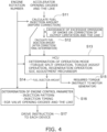
- Fig. 4 is a flowchart illustrating an outline of the operation of the hybrid system according to this embodiment.
- the fuel injection-amount calculation unit 511 calculates the fuel injection amount of the engine 3 on the basis of at least either one of the accelerator opening degree detected by the accelerator opening-degree sensor 61 and the rotation-number signal transmitted by the hand accelerator 62.
- the fuel injection amount calculated at Step S11 is the fuel injection amount before correction in order to avoid excessive emission of particulate matters (PM: Particulate Matter) contained in the exhaust gas or to avoid excess of a limit value by an output of the engine 3 is conducted.
- the system required-torque calculation unit 512 calculates the system required torque on the basis of the rotation number of the engine 3 detected by the rotation sensor 31 and the fuel injection amount (that is, the fuel injection amount before the correction) calculated by the fuel injection-amount calculation unit 511.
- the engine required-torque calculation unit 513 corrects the fuel injection amount calculated by the fuel injection-amount calculation unit 511 in order to avoid excessive emission of the particulate matters contained in the exhaust gas and to avoid excess of the limit value by the output of the engine 3 and finally determines the maximum fuel injection amount. Then, the engine required-torque calculation unit 513 calculates the engine required torque on the basis of the rotation number of the engine 3 detected by the rotation sensor 31 and the fuel injection amount after the correction.
- the operation-mode determination unit 515 determines the operation mode (the regeneration operation, the torque assist operation, the torque split operation) of the hybrid system 2 on the basis of the system required torque calculated by the system required-torque calculation unit 512 and the engine required torque calculated by the engine required-torque calculation unit 513.
- the operation-mode determination unit 515 determines the operation mode of the hybrid system 2 on the basis of the system required torque calculated by the system required-torque calculation unit 512, the engine required torque calculated by the engine required-torque calculation unit 513, and the rotation number of the engine 3 detected by the rotation sensor 31.
- the operation-mode determination unit 515 adjusts the charging rate of the battery pack 42 by determining the operation mode of the hybrid system 2 further on the basis of the charging rate (SOC) of the battery pack 42.
- the calculation and processing at Step S13 are executed by the HCU, for example.
- the fuel injection-amount calculation unit 511 calculates the fuel injection amount of the engine 3 on the basis of the operation mode of the hybrid system 2 determined by the operation-mode determination unit 515. That is, the fuel injection-amount calculation unit 511 writes back (that is, converts) the fuel injection amount of the engine 3 on the basis of the operation mode of the hybrid system 2 determined by the operation-mode determination unit 515.
- the motor required-torque calculation unit 514 calculates the motor required torque on the basis of the operation mode of the hybrid system 2 determined by the operation-mode determination unit 515. Then, the control unit 5 transmits a signal related to the motor required torque calculated by the motor required-torque calculation unit 514 to the motor generator 41 and gives an instruction to the motor generator 41.
- the engine control-parameter determination unit 516 determines the control parameter of the engine 3 on the basis of the fuel injection amount written back by the fuel injection-amount calculation unit 511 and the rotation number of the engine 3 detected by the rotation sensor 31.
- Step S17 the control unit 5 transmits a signal related to the control parameter determined by the engine control-parameter determination unit 516 and gives a drive instruction to each device.
- the control unit 5 corrects the fuel injection amount calculated by the fuel injection-amount calculation unit 511 and calculates the engine required torque on the basis of the rotation number of the engine 3 detected by the rotation sensor 31 and the fuel injection amount after the correction.
- the torque assist operation can be performed while the particulate matters contained in the exhaust gas are reduced.
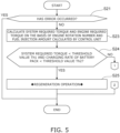
- Fig. 5 and Fig. 6 are flowcharts illustrating a specific example of the operations of the hybrid system according to this embodiment.
- Fig. 7 is a table exemplifying the map data in this embodiment.
- Step S21 the control unit 5 determines whether an error has occurred in the hybrid system 2 or not. If an error has occurred in the hybrid system 2 (Step S21: YES), the control unit 5 ends the operation of the hybrid system 2.
- Step S23 the fuel injection-amount calculation unit 511 calculates the fuel injection amount of the engine 3 on the basis of at least either one of the accelerator opening degree detected by the accelerator opening-degree sensor 61 and the rotation-number signal transmitted by the hand accelerator 62. Then, the system required-torque calculation unit 512 calculates the system required torque on the basis of the rotation number of the engine 3 detected by the rotation sensor 31 and the fuel injection amount (that is, the fuel injection amount before the correction) calculated by the fuel injection-amount calculation unit 511.
- the engine required-torque calculation unit 513 corrects the fuel injection amount calculated by the fuel injection-amount calculation unit 511 and calculates the engine required torque on the basis of the rotation number of the engine 3 detected by the rotation sensor 31 and the fuel injection amount after the correction.
- the "fuel injection amount before the correction” and the “fuel injection amount after the correction” are as described above in relation with Fig. 4 .
- the control unit 5 of this embodiment calculates the system required torque and the engine required torque on the basis of the map data 522 stored in the storage unit 52 in advance.
- the map data 522 shown in Fig. 7 is stored in the storage unit 52 (held in a storage), for example.
- a lateral axis indicates the rotation number of the engine 3 and a vertical axis indicates the fuel injection amount of the engine 3.
- a portion where the lateral axis (engine rotation number) and the vertical axis (fuel injection amount) cross each other indicates the torque of the engine 3. That is, the map data 522 exemplified in Fig. 7 indicates the relationship of the rotation number of the engine 3, the fuel injection amount of the engine 3, and the torque of the engine 3.
- a relatively right side is a side where the rotation number of the engine 3 is relatively high
- a relatively left side is a side where the rotation number of the engine 3 is relatively low
- a relatively lower side is a side where the fuel injection amount of the engine 3 is relatively larger
- a relatively upper side is a side where the fuel injection amount of the engine 3 is relatively smaller.
- a case in which the fuel injection-amount calculation unit 511 calculates a fuel injection amount Q8 of the engine 3 on the basis of at least either one of the accelerator opening degree detected by the accelerator opening-degree sensor 61 and the rotation-number signal transmitted by the hand accelerator 62 is cited as an example.
- the fuel injection amount Q8 is an example of the "fuel injection amount before the correction”.
- a case in which the rotation sensor 31 detects a rotation number R3 of the engine 3 is cited as an example.
- the system required-torque calculation unit 512 calculates a system required torque T38 on the basis of the rotation number R3 of the engine 3 and the fuel injection amount Q8 before the correction. Subsequently, the engine required-torque calculation unit 513 corrects the fuel injection amount Q8 calculated by the fuel injection-amount calculation unit 511 in order to avoid excessive emission of the particulate matters contained in the exhaust gas and to avoid excess of the limit value by the output of the engine 3 and finally determines a maximum fuel injection amount Q5.
- the fuel injection amount Q5 is an example of the "fuel injection amount after the correction".
- the engine required-torque calculation unit 513 calculates an engine required torque T35 on the basis of the rotation number R3 of the engine 3 and the fuel injection amount Q5 after the correction.
- the control unit 5 of this embodiment calculates the system required torque T38 and the engine required torque T35 on the basis of the map data 522 stored in the storage unit 52 in advance.
- the control unit 5 determines whether the system required torque T38 is smaller than a threshold value Th1 and the charging rate of the battery pack 42 is smaller than a threshold value Th2 or not.
- the threshold value Th1 of this embodiment is an example of the "first threshold value” of the present invention.
- the threshold value Th2 of this embodiment is an example of the "second threshold value" of the present invention.
- Step S24 when all the conditions of "system required torque T38 ⁇ threshold value Th1" and of “charging rate of the battery pack 42 ⁇ threshold value Th2" are satisfied (Step S24: YES), at Step S25, the operation-mode determination unit 515 determines the regeneration operation as the operation mode of the hybrid system 2 and performs the regeneration operation.
- the operation-mode determination unit 515 determines the regeneration operation as the operation mode of the hybrid system 2.
- the fuel injection-amount calculation unit 511 calculates the fuel injection amount of the engine 3 on the basis of the operation mode (regeneration operation at Step S25) of the hybrid system 2 determined by the operation-mode determination unit 515. Specifically, the fuel injection-amount calculation unit 511 sets the fuel injection amount of the engine 3 to zero. In other words, the engine required-torque calculation unit 513 sets the engine required torque to zero.
- the motor required-torque calculation unit 514 calculates the motor required torque on the basis of the operation mode (regeneration operation at Step S25) of the hybrid system 2 determined by the operation-mode determination unit 515. Specifically, the motor required-torque calculation unit 514 calculates the motor required torque for charging the battery pack 42 by the motor generator 41. That is, the motor required-torque calculation unit 514 sets the motor required torque to zero.
- Step S24 if at least either one of the conditions of "system required torque T38 ⁇ threshold value Th1" and of “charging rate of the battery pack 42 ⁇ threshold value Th2" is not satisfied (Step S24: NO), at Step S31, the control unit 5 determines whether the system required torque T38 is larger than the engine required torque T35 and the charging rate of the battery pack 42 is larger than the threshold value Th2 or not.
- Step S31 when all the conditions of "system required torque T38 > engine required torque T35" and of “charging rate of the battery pack 42 > threshold value Th2" are satisfied (Step S31: YES), at Step S32, the operation-mode determination unit 515 determines the torque assist operation as the operation mode of the hybrid system 2 and performs the torque assist operation.
- the operation-mode determination unit 515 determines the torque assist operation as the operation mode of the hybrid system 2.
- the fuel injection-amount calculation unit 511 calculates the fuel injection amount of the engine 3 on the basis of the operation mode (torque assist operation at Step S32) of the hybrid system 2 determined by the operation-mode determination unit 515.
- the motor required-torque calculation unit 514 calculates the motor required torque on the basis of the operation mode (torque assist operation at Step S32) of the hybrid system 2 determined by the operation-mode determination unit 515.
- the motor required-torque calculation unit 514 calculates the motor required torque on the basis of the difference between the system required torque T38 and the engine required torque T35. That is, the motor required-torque calculation unit 514 calculates the motor required torque for the motor generator 41 to assist the torque of the engine 3.
- the hybrid system 2 can improve a work by the industrial machine on which the hybrid system 2 is mounted.
- Step S31 if at least either one of the conditions of "system required torque T38 > engine required torque T35" and of “charging rate of the battery pack 42 > threshold value Th2" is not satisfied, or in other words, at least either one of the conditions of "system required torque T38 ⁇ engine required torque T35" and “charging rate of the battery pack 42 ⁇ threshold value Th2" is satisfied (Step S31: NO), at Step S33, the operation-mode determination unit 515 determines the torque split operation as the operation mode of the hybrid system 2 and performs the torque split operation.
- the operation-mode determination unit 515 determines the torque split operation as the operation mode of the hybrid system 2.
- the fuel injection-amount calculation unit 511 calculates the fuel injection amount of the engine 3 on the basis of the operation mode (torque split operation at Step S33) of the hybrid system 2 determined by the operation-mode determination unit 515.
- the motor required-torque calculation unit 514 calculates the motor required torque on the basis of the operation mode (torque split operation at Step S33) of the hybrid system 2 determined by the operation-mode determination unit 515.
- the fuel injection-amount calculation unit 511 calculates the fuel injection amount for generating the torque of 100 N ⁇ m in the engine 3, for example.
- the fuel injection-amount calculation unit 511 sets the fuel injection amount of the engine 3 to zero, and the motor required-torque calculation unit 514 calculates the motor required torque for the motor generator 41 to assist the torque of 100 N.m for the engine 3.
- the fuel injection-amount calculation unit 511 calculates the fuel injection amount for generating the torque of 50 N ⁇ m in the engine 3, and the motor required-torque calculation unit 514 calculates the motor required torque for the motor generator 41 to assist the torque of 50 N.m for the engine 3, for example.
- the fuel injection-amount calculation unit 511 calculates the fuel injection amount for generating the torque of 130 N ⁇ m in the engine 3, and the motor required-torque calculation unit 514 calculates the torque of excessive 30 N ⁇ m in the engine 3 as the motor required torque for charging the battery pack 42 by the motor generator 41, for example.
- Step S31 NO
- the control unit 5 can bring the charging rate of the battery pack 42 closer to the target value by distributing the torque of the engine 3 and the torque of the motor generator 41.
- Step S25 Step S32, and Step S33, the control unit 5 ends the operation of the hybrid system 2.
- the control unit 5 corrects the fuel injection amount Q8 calculated by the fuel injection-amount calculation unit 511 and calculates the engine required torque T35 on the basis of the rotation number R3 of the engine 3 detected by the rotation sensor 31 and the fuel injection amount Q5 after the correction.
- the torque assist operation can be performed while reducing the particulate matters contained in the exhaust gas.
- control unit 5 calculates the system required torque T38 and the engine required torque T35 on the basis of the map data 522 stored in the storage unit 52 in advance. Therefore, the control unit 5 can calculate the more proper system required torque T38 and engine required torque T35 while reducing the processing time for calculating the system required torque T38 and the engine required torque T35.
- control unit 5 determines the operation mode on the basis not only of the relationship between the system required torque T38 and the engine required torque T35 but further of the charging rate of the battery pack 42 connected to the motor generator 41. Therefore, the control unit 5 can determine the more proper operation mode while the input factors which can be used when determining the operation mode are limited.
- Fig. 8 is a graph illustrating a torque curve of the hybrid system according to this embodiment.
- the lateral axis of the graph shown in Fig. 8 indicates the rotation number of the engine 3.
- the vertical axis of the graph shown in Fig. 8 indicates the torque of the engine 3.
- the control unit 5 (specifically, the system required-torque calculation unit 512) of this embodiment calculates the system required torque larger than the torque generated only by the engine 3 in all the regions of the rotation number of the engine 3. That is, the control unit 5 executes the control in which the motor generator 41 assists or supports the torque of the engine 3 in order to generate the torque in a region which cannot be generated singularly by the engine 3 in all the regions of the rotation number of the engine 3. In other words, the control unit 5 does not execute the control in which the motor generator 41 assists or supports the torque of the engine 3 in the torque region which can be generated singularly by the engine 3.
- control unit 5 can cause the system required torque larger than the torque generated only by the engine 3 to be generated by executing the torque-assist operation as the more proper operation mode even when the rotation number of the engine 3 is relatively low.
- the fuel consumption can be improved while suppressing the emission of the engine 3 and reducing the particulate matters contained in the exhaust gas.
- the calculation unit 51 may calculate a target air amount as the torque determining factor for determining the system required torque.
- the calculation unit 51 calculates a target air amount of the engine 3 on the basis of at least either one of the accelerator opening degree detected by the accelerator opening-degree sensor 61 and the rotation-number signal transmitted by the hand accelerator 62.
- the calculation unit 51 calculates the system required torque as the hybrid system 2 on the basis of the rotation number of the engine 3 detected by the rotation sensor 31 and the calculated target air amount of the engine 3.
Landscapes
- Engineering & Computer Science (AREA)
- Transportation (AREA)
- Mechanical Engineering (AREA)
- Chemical & Material Sciences (AREA)
- Combustion & Propulsion (AREA)
- Automation & Control Theory (AREA)
- Hybrid Electric Vehicles (AREA)
- Combined Controls Of Internal Combustion Engines (AREA)
- Control Of Vehicle Engines Or Engines For Specific Uses (AREA)
- Electric Propulsion And Braking For Vehicles (AREA)
Abstract
Description
- The present invention relates to a hybrid system mounted on an industrial machine.
- In a hybrid system mounted on a hybrid vehicle, for example, a control unit (ECU: Electronic Control Unit) calculates a required torque as a hybrid system in order to determine an operation mode of the hybrid system. As the operation mode of the hybrid system, a torque split operation, a torque assist operation, a regeneration operation and the like can be cited, for example.
- The torque split operation is an operation which brings a charging rate of a battery closer to a target value by distributing a torque of an engine and a torque of a motor generator. The torque assist operation is an operation in which the motor generator assists the engine torque. The regeneration operation is an operation in which fuel injection of the engine is stopped, and the battery is charged by the motor generator.
- PTL 1 discloses a hybrid vehicle including a hybrid system having an electric generator connected to a battery and an engine and control means which controls the hybrid system. In the hybrid vehicle described in
PTL 1, the control means works out an increase rate of a fuel consumption amount with respect to an output torque in the engine on the basis of a required torque to the engine calculated from measured values of a rotation sensor which measures an engine rotation number of the engine and an accelerator opening-degree sensor which measures an opening degree of an accelerator in the hybrid vehicle and on the basis of map data set in advance. And when a maximum value of the increase rate of the fuel consumption amount exceeds a threshold value set in advance, the control means executes control such that the assist of the engine by the electric generator is started with a maximum allowable drive output of the electric generator at a measured value of a temperature sensor. - In the hybrid system of an automobile as disclosed in
PTL 1, for example, the required torque as the hybrid system is calculated on the basis not only of an engine required torque based on an accelerator pedal input (in other words, an accelerator opening degree) but also of a required torque for each component such as a transmission, an air conditioner and the like. In order to implement the calculation of the required torque as the hybrid system as above, each ECU provided for each component calculates a required torque for each component. - However, in industrial machines such as a construction machine, an agricultural machine, a lawnmower, a generator, a compressor, a pump and the like, a configuration of an accelerator is different for each application. For example, there is an industrial machine of such a model that does not include an accelerator pedal. In the industrial machine of the model that does not include an accelerator pedal, an operator instructs a certain engine rotation number not by the accelerator pedal but by a dial switch called a hand accelerator or the like in order to perform a work at a certain engine rotation number. Moreover, in the industrial machines, a relatively few components other than the engine have ECU, and the required torques of the components other than the engine are not known in relatively many cases. As described above, in the hybrid system mounted on the industrial machines, there is a problem that input factors which can be used when the required torque as the hybrid system is calculated or input factors which can be used when the required torque as the hybrid system is calculated and can be used when an operation mode of the hybrid system is determined are limited, as compared with the hybrid system mounted on automobiles.
- [PTL 1]
Japanese Patent Application Publication No. 2016-107669 - The present invention has been made in order to solve the aforementioned problem and has an object to provide a hybrid system which can calculate various types of more proper required torques when input factors which can be used when the various types of required torques are calculated are limited. Alternatively, it has an object to provide a hybrid system which can determine more proper operation mode while the input factors which can be used when the operation mode is determined are limited.
- The aforementioned problem is solved by a hybrid system according to the present invention mounted on an industrial machine, the hybrid system including a rotation sensor which detects a rotation number of an engine, at least either one of an accelerator opening-degree sensor which detects an accelerator opening degree and a rotation-number instruction unit which transmits a rotation-number signal instructing the certain rotation number to the engine, and a control unit which controls an operation of the engine, characterized in that the control unit executes control of calculating a torque determining factor for determining a system required torque as the hybrid system on the basis of at least either one of the accelerator opening degree detected by the accelerator opening-degree sensor and the rotation-number signal transmitted by the rotation-number instruction unit, and control of calculating the system required torque on the basis of the rotation number detected by the rotation sensor and the calculated torque determining factor.
- According to the hybrid system according to the present invention, the control unit calculates the torque determining factor for determining the system required torque as the hybrid system on the basis of at least either one of the accelerator opening degree detected by the accelerator opening-degree sensor and the rotation-number signal transmitted by the rotation-number instruction unit. That is, the control unit can calculate the torque determining factor on the basis of the accelerator opening degree detected by the accelerator opening-degree sensor, can calculate the torque determining factor on the basis of the rotation-number signal which is transmitted by the rotation-number instruction unit and instructs a certain rotation number to the engine, and can calculate the torque determining factor on the basis of both the accelerator opening degree and the rotation-number signal. And the control unit calculates the system required torque as the hybrid system on the basis of the engine rotation number detected by the rotation sensor and the calculated torque determining factor. Thus, even if the hybrid system is mounted on the industrial machine not including an accelerator pedal, for example, or even if the control unit is not installed on the components other than the engine, the control unit of the present invention can calculate more proper system required torque. As a result, the hybrid system according to the present invention can calculate the more proper system required torque while the input factors which can be used when calculating the system required torque are limited.
- In the hybrid system according to the present invention, the torque determining factor is preferably characterized to be a fuel injection amount of the engine.
- According to the hybrid system according to the present invention, the control unit calculates the fuel injection amount of the engine on the basis of at least either one of the accelerator opening degree detected by the accelerator opening-degree sensor and the rotation-number signal transmitted by the rotation-number instruction unit. And the control unit calculates the system required torque as the hybrid system on the basis of the rotation number of the engine detected by the rotation sensor and the calculated fuel injection amount of the engine. Thus, the hybrid system according to the present invention can calculate the more proper system required torque while the input factors which can be used when calculating the system required torque are limited.
- In the hybrid system according to the present invention, the control unit is preferably characterized by correcting the calculated fuel injection amount and by calculating an engine required torque for the engine on the basis of the rotation number detected by the rotation sensor and the fuel injection amount after the correction.
- According to the hybrid system according to the present invention, the control unit corrects the fuel injection amount and calculates the engine required torque on the basis of the rotation number of the engine detected by the rotation sensor and the fuel injection amount after the correction. As a result, while reducing particulate matters (PM: Particulate Matter) contained in an exhaust gas, the torque assist operation can be performed when the rotation number of the engine is lowered due to an overload or a rapid acceleration response is required.
- In the hybrid system according to the present invention, the control unit is preferably characterized by storing, in advance, map data indicating a relationship among the rotation number of the engine, the fuel injection amount, and the torque of the engine and by calculating the system required torque on the basis of the map data stored in advance.
- According to the hybrid system according to the present invention, since the control unit calculates the system required torque on the basis of the map data stored in advance, it can calculate the more proper system required torque while reducing processing time for calculating the system required torque.
- In the hybrid system according to the present invention, the control unit is preferably characterized by storing, in advance, map data indicating a relationship among the rotation number of the engine, the fuel injection amount, and the torque of the engine and by calculating the engine required torque on the basis of the map data stored in advance.
- According to the hybrid system according to the present invention, since the control unit calculates the engine required torque on the basis of the map data stored in advance, it can calculate the more proper engine required torque while reducing processing time for calculating the engine required torque.
- In the hybrid system according to the present invention, the control unit is preferably characterized by calculating the system required torque, which is larger than a torque generated only by the engine.
- According to the hybrid system according to the present invention, the control unit can perform the torque assist operation and can generate the system required torque larger than the torque generated only by the engine, even when the rotation number of the engine is relatively low. As a result, fuel efficiency can be improved while suppressing an emission of the engine, and reducing particulate matters contained in the exhaust gas.
- The aforementioned problem is solved by the hybrid system according to the present invention, which is a hybrid system mounted on an industrial machine and includes a rotation sensor which detects a rotation number of an engine, at least either one of an accelerator opening-degree sensor which detects an accelerator opening degree and a rotation-number instruction unit which transmits a rotation-number signal instructing the certain rotation number to the engine, and a control unit which controls an operation of the engine, characterized in that the control unit executes control of calculating a torque determining factor for determining a system required torque as the hybrid system on the basis of at least either one of the accelerator opening degree detected by the accelerator opening-degree sensor and the rotation-number signal transmitted by the rotation-number instruction unit, control of calculating the system required torque and the engine required torque for the engine on the basis of the rotation number detected by the rotation sensor and the calculated torque determining factor, and control of determining an operation mode on the basis of the relationship between the system required torque and the engine required torque.
- According to the hybrid system according to the present invention, the control unit calculates the torque determining factor for determining the system required torque as the hybrid system on the basis of at least either one of the accelerator opening degree detected by the accelerator opening-degree sensor and the rotation-number signal transmitted by the rotation-number instruction unit. That is, the control unit can calculate the torque determining factor on the basis of the accelerator opening degree detected by the accelerator opening-degree sensor, can calculate the torque determining factor on the basis of the rotation-number signal which is transmitted by the rotation-number instruction unit and instructs a certain rotation number to the engine and can also calculate the torque determining factor on the basis of both the accelerator opening degree and the rotation-number signal. And the control unit calculates the system required torque as the hybrid system and the engine required torque for the engine on the basis of the engine rotation number detected by the rotation sensor and the calculated torque determining factor and executes control of determining the operation mode on the basis of the system required torque and the engine required torque. Thus, even if the hybrid system is mounted on the industrial machine not including an accelerator pedal, for example, or even if the control unit is not installed in the components other than the engine, the control unit of the present invention can calculate the more proper system required torque and engine required torque and can determine the more proper operation mode on the basis of the relationship between the system required torque and the engine required torque. As a result, the hybrid system according to the present invention can determine the more proper operation mode while the input factors which can be used when determining the operation mode are limited.
- In the hybrid system according to the present invention, the torque determining factor is preferably characterized to be a fuel injection amount of the engine.
- According to the hybrid system according to the present invention, the control unit calculates the fuel injection amount of the engine on the basis of at least either one of the accelerator opening degree detected by the accelerator opening-degree sensor and the rotation-number signal transmitted by the rotation-number instruction unit. And the control unit executes control of calculating the system required torque and the engine required torque for the engine as the hybrid system on the basis of the rotation number of the engine detected by the rotation sensor and the calculated fuel injection amount of the engine and of determining the operation mode on the basis of the relationship between the system required torque and the engine required torque. Thus, the hybrid system according to the present invention can determine the more proper operation mode while the input factors which can be used when determining the operation mode are limited.
- In the hybrid system according to the present invention, the control unit is preferably characterized by correcting the calculated fuel injection amount and by calculating the engine required torque on the basis of the rotation number detected by the rotation sensor and the fuel injection amount after the correction.
- According to the hybrid system according to the present invention, the control unit corrects the fuel injection amount and calculates the engine required torque on the basis of the rotation number of the engine detected by the rotation sensor and the fuel injection amount after the correction. As a result, while reducing the particulate matters (PM: Particulate Matter) contained in an exhaust gas, the torque assist operation can be performed as the more proper operation mode, when the rotation number of the engine is lowered due to an overload or a rapid acceleration response is required.
- In the hybrid system according to the present invention, the control unit is preferably characterized by storing, in advance, map data indicating the relationship among the rotation number of the engine, the fuel injection amount, and the torque of the engine and by calculating the system required torque and the engine required torque on the basis of the map data stored in advance.
- According to the hybrid system according to the present invention, since the control unit calculates the system required torque and the engine required torque on the basis of the map data stored in advance, it can calculate the more proper system required torque and engine required torque while reducing processing time for calculating the system required torque and the engine required torque.
- In the hybrid system according to the present invention, the control unit is preferably characterized by executing control of determining the operation mode further on the basis of a charging rate of a battery connected to the motor generator.
- According to the hybrid system according to the present invention, the control unit executes control of determining the operation mode on the basis not only of the relationship between the system required torque and the engine required torque but further of the charging rate of the battery connected to the motor generator. Therefore, the hybrid system according to the present invention can determine the more proper operation mode while the input factors which can be used when determining the operation mode are limited.
- In the hybrid system according to the present invention, the control unit is preferably characterized in that, when the system required torque is smaller than a first threshold value, and the charging rate is smaller than a second threshold value, the engine required torque is set to zero, and the motor required torque for the motor generator is calculated, and a regeneration operation for charging the battery by the motor generator is determined to be the operation mode.
- According to the hybrid system according to the present invention, the control unit calculates the motor required torque for the motor generator on the basis of the relationship between the system required torque and the engine required torque and the charging rate of the battery and can execute the regeneration operation as the more proper operation mode.
- In the hybrid system according to the present invention, the control unit is preferably characterized in that, when the system required torque is larger than the engine required torque, and when the charging rate is larger than the second threshold value, the motor required torque for the motor generator is calculated on the basis of a difference between the system required torque and the engine required torque, and the torque assist operation, in which the motor generator assists a torque of the engine is determined, to be the operation mode.
- According to the hybrid system according to the present invention, the control unit calculates the motor required torque for the motor generator on the basis of the relationship between the system required torque and the engine required torque and of the charging rate of the battery and can execute the torque assist operation as the more proper operation mode.
- In the hybrid system according to the present invention, the control unit is preferably characterized in that, at least in either one of a case when the system required torque is equal to or less than the engine required torque, and a case when the charging rate is equal to or less than the second threshold value, the motor required torque for the motor generator is calculated in accordance with the charging rate, and a torque split operation for bringing the charging rate closer to a target value by distributing the torque of the engine and the torque of the motor generator is determined to be the operation mode.
- According to the hybrid system according to the present invention, the control unit calculates the motor required torque for the motor generator on the basis of the relationship between the system required torque and the engine required torque and of the charging rate of the battery and can execute the torque split operation as the more proper operation mode.
- In the hybrid system according to the present invention, the control unit is preferably characterized by calculating the system required torque, which is larger than a torque generated only by the engine.
- According to the hybrid system according to the present invention, the control unit executes the torque assist operation as the more proper operation mode and can generate the system required torque larger than the torque generated only by the engine, even when the rotation number of the engine is relatively low. As a result, improvement of the fuel consumption can be promoted while suppressing the emission of the engine, and reducing the particulate matters contained in the exhaust gas.
- According to the present invention, while the input factors which can be used when calculating various required torques are limited, the hybrid system which can calculate the more proper various required torques can be provided. Moreover, according to the present invention, while the input factors which can be used when determining the operation mode are limited, the hybrid system which can determine the more proper operation mode can be provided.
-
- [
Fig. 1 ]
Fig. 1 is a block diagram illustrating a hybrid system according to a first embodiment of the present invention. - [
Fig. 2 ]
Fig. 2 is a block diagram illustrating a hybrid system according to a second embodiment of the present invention. - [
Fig. 3 ]
Fig. 3 is a block diagram illustrating an essential-part configuration of the hybrid system according to this embodiment. - [
Fig. 4 ]
Fig. 4 is a flowchart illustrating an outline of an operation of the hybrid system according to this embodiment. - [
Fig. 5 ]
Fig. 5 is a flowchart illustrating a specific example of the operation of the hybrid system according to this embodiment. - [
Fig. 6 ]
Fig. 6 is a flowchart illustrating a specific example of the operation of the hybrid system according to this embodiment. - [
Fig. 7 ]
Fig. 7 is a table exemplifying map data of this embodiment. - [
Fig. 8 ]
Fig. 8 is a graph illustrating a torque curve of the hybrid system according to this embodiment. - Hereinafter, preferred embodiments of the present invention will be described in detail by referring to the figures.
- The embodiments described below are preferred specific examples of the present invention and thus, various technically preferable limitations are given, but a scope of the present invention is not limited to these modes unless it is particularly described that the present invention is limited in the following description. Moreover, in each of the drawings, the same signs are given to the similar constituent elements, and detailed description will be omitted as appropriate.
-
Fig. 1 is a block diagram illustrating a hybrid system according to a first embodiment of the present invention. - A
hybrid system 2A according to this embodiment is mounted on industrial machine such as a construction machine, an agricultural machine, a lawnmower, a generator, a compressor, a pump or the like, for example. As shown inFig. 1 , the industrial machine on which thehybrid system 2A according to this embodiment is mounted is a machine having anaccelerator pedal 65 so that a rotation number of anengine 3 is made variable by theaccelerator pedal 65. Thehybrid system 2A includes theengine 3, amotor generator 41, abattery pack 42, a DC/DC converter 43, acontrol unit 5, and an accelerator opening-degree sensor 61. - The
engine 3 is an internal combustion engine, that is, an industrial engine such as an industrial diesel engine, an industrial gasoline engine, an industrial gas engine and the like, for example. Theengine 3 is a multicylinder engine such as a supercharging type high-output 3-cylinder engine, a 4-cylinder engine and the like with a turbocharger, for example. As shown inFig. 1 , theengine 3 has arotation sensor 31, a DOC (Diesel Oxidation Catalyst) 32, and a DPF (Diesel Particulate Filter) 33. However, theengine 3 is not limited to the configuration shown inFig. 1 but does not have to include the DOC or the DPF. Moreover, theengine 3 only needs to be configured such that fuel injection is electronically controlled, not limited to a common rail, but a governor maybe electronically controlled. - The
rotation sensor 31 detects the rotation number of theengine 3 and transmits a voltage signal related to the rotation number of theengine 3 to thecontrol unit 5 via a CAN (Controller Area Network) communication line. Thecontrol unit 5 converts the received voltage signal related to the rotation number of theengine 3 to the rotation number. Power generated in theengine 3 is transmitted to power taking-outcomponents 71 such as a hydraulic pump, a transmission (T/M) and the like of the industrial machine. - The
motor generator 41 is an AC power generator and is connected to theengine 3 through atransmission member 34 such as a V-belt or the like. Themotor generator 41 is driven by power generated in theengine 3 and transmitted through thetransmission member 34 and generates electricity. Moreover, when the rotation number of the engine is lowered due to an overload or when rapid acceleration response is required, for example, themotor generator 41 generates a rotary force by power supplied from thebattery pack 42, transmits the rotary force to theengine 3 through thetransmission member 34, and assists or supports a torque of theengine 3. Details thereof will be described later. - The
battery pack 42 is a lithium-ion battery, for example, and is electrically connected to themotor generator 41. Thebattery pack 42 of this embodiment is an example of the "battery" of the present invention. Thebattery pack 42 is electrically connected to themotor generator 41 by a 48-V system line, for example, and stores electricity generated by themotor generator 41. That is, thebattery pack 42 performs charging by power generation of themotor generator 41. Moreover, thebattery pack 42 supplies the stored electricity to themotor generator 41. That is, thebattery pack 42 discharges when themotor generator 41 requires electricity and supplies power to themotor generator 41. - The DC/
DC converter 43 is electrically connected to thebattery pack 42 by a high-voltage system line such as 48V or 24V, for example, and converts a high-voltage DC current discharged from thebattery pack 42 to a low-voltage DC current such as 12V. Moreover, the DC/DC converter 43 is electrically connected to alead battery 72 by a low-voltage system line, for example. The electricity which was converted by the DC/DC converter 43 from the high-voltage DC current to the low-voltage DC current is stored in thelead battery 72. The electricity stored in thelead battery 72 is supplied to anelectric load 73 such as a light, an electric heater, a wiper and the like of the industrial machine. - As described above, the industrial machine on which the
hybrid system 2A according to this embodiment is mounted has theaccelerator pedal 65. The accelerator opening-degree sensor 61 detects an input of theaccelerator pedal 65, that is, an accelerator opening degree and transmits a signal related to the accelerator opening degree to thecontrol unit 5 by the CAN communication line. - The
control unit 5 includes an ECU (electronic control unit or engine control unit) and an HCU (Hybrid Control Unit: hybrid control unit) and controls thehybrid system 2A. The HCU may be provided integrally with the ECU or may be provided separately from the ECU. - The
control unit 5 performs calculation by acquiring various types of information or by receiving various signals, generates control signals which control operations of components such as theengine 3, themotor generator 41, thebattery pack 42 and the like, and transmit them to each component by electric communication lines including the CAN. For example, thecontrol unit 5 gives drive instructions to each component by transmitting the control signal to each component by the electric communication line by calculating a fuel injection amount of theengine 3, by calculating a target air amount of theengine 3, by determining the operation mode of thehybrid system 2A, or by determining a control parameter of theengine 3. - The operation modes of the
hybrid system 2A include, for example, a torque split operation, a torque assist operation, a regeneration operation and the like. The torque split operation is an operation of distributing the torque of theengine 3 and the torque of themotor generator 41 so as to bring the charging rate of thebattery pack 42 to a target value. The torque assist operation is an operation in which themotor generator 41 assists or supports the torque of theengine 3. The regeneration operation is an operation of stopping fuel injection of theengine 3 and of charging thebattery pack 42 by themotor generator 41. Details of the operation modes of thehybrid system 2A will be described later. -
Fig. 2 is a block diagram illustrating a hybrid system according to a second embodiment of the present invention. - When constituent elements of the
hybrid system 2B according to the second embodiment are similar to the constituent elements of thehybrid system 2A according to the first embodiment described above in relation withFig. 1 , duplicated description will be omitted as appropriate, and mainly differences will be described below. - The
hybrid system 2B according to this embodiment is, similarly to thehybrid system 2A described above in relation withFig. 1 , mounted on industrial machine such as a construction machine, an agricultural machine, a lawnmower, a generator, a compressor, a pump or the like, for example. As shown inFig. 2 , the industrial machine on which thehybrid system 2B according to this embodiment is mounted is a machine having ahand accelerator 62 instead of theaccelerator pedal 65 so that a rotation number of anengine 3 is set to a certain level by thehand accelerator 62. - An operator of the industrial machine on which the
hybrid system 2B is mounted gives an instruction of a certain engine rotation number by thehand accelerator 62 in order to perform a work at the certain engine rotation number. Thehand accelerator 62 is a dial switch, for example, and receives the certain rotation number of theengine 3 input by the operator in accordance with an operation of the operator to thehand accelerator 62 and transmits a rotation-number signal instructing the certain rotation number of theengine 3 to thecontrol unit 5 by the CAN communication line. Thehand accelerator 62 of this embodiment is an example of a "rotation-number instruction unit" of the present invention. The "rotation-number instruction unit" of the present invention is not limited only to thehand accelerator 62. - The other constituent elements are similar to the constituent elements of the
hybrid system 2A according to the first embodiment described above in relation withFig. 1 . - In the following description, for convenience of explanation, the
hybrid system 2A according to the first embodiment and thehybrid system 2B according to the second embodiment are called the "hybrid system 2" as a concept containing the both in some cases. As described in relation withFig. 1 andFig. 2 , thehybrid system 2 according to this embodiment is mounted on an industrial machine of a model including theaccelerator pedal 65 or is mounted on an industrial machine of a model not including the accelerator pedal 65 (in other words, a model including the hand accelerator 62) depending on the case. Moreover, thehybrid system 2 according to this embodiment may be mounted on an industrial machine of a model including both theaccelerator pedal 65 and thehand accelerator 62. - Subsequently, the
control unit 5 of this embodiment will be further described by referring to the figures. -
Fig. 3 is a block diagram illustrating an essential part configuration of the hybrid system according to this embodiment. - The
control unit 5 of this embodiment has acalculation unit 51, astorage unit 52, and acommunication unit 53. Thecalculation unit 51 executes various calculations and processing by reading out aprogram 521 stored in thestorage unit 52. Thestorage unit 52 stores (holds in a storage) theprogram 521 executed by thecalculation unit 51 andmap data 522 used when the system required torque and the engine required torque, which will be described later, are to be calculated. Details of themap data 522 will be described later. The data stored in thestorage unit 52 is not limited to theprogram 521 and themap data 522. As thestorage unit 52, a ROM (Read Only Memory), a RAM (Random Access Memory) and the like are cited. Theprogram 521 is not limited to being stored in thestorage unit 52, but it may be stored in a recording medium which can be read by thecalculation unit 51 in advance and distributed or it may be downloaded to thecontrol unit 5 via a network. Moreover, thestorage unit 52 may be an external storage device connected to thecontrol unit 5. - The
calculation unit 51 has a fuel injection-amount calculation unit 511, a system required-torque calculation unit 512, an engine required-torque calculation unit 513, a motor required-torque calculation unit 514, an operation-mode determination unit 515, and an engine control-parameter determination unit 516. Thecalculation unit 51 may have a target air-amount calculation unit (not shown) instead of or together with the fuel injection-amount calculation unit 511. The fuel injection-amount calculation unit 511, the system required-torque calculation unit 512, the engine required-torque calculation unit 513, the motor required-torque calculation unit 514, the operation-mode determination unit 515, the engine control-parameter determination unit 516, and the target air-amount calculation unit are realized by execution of theprogram 521 stored in thestorage unit 52 by thecalculation unit 51. The fuel injection-amount calculation unit 511, the system required-torque calculation unit 512, the engine required-torque calculation unit 513, the motor required-torque calculation unit 514, the operation-mode determination unit 515, the engine control-parameter determination unit 516, and the target air-amount calculation unit may be realized by hardware or may be realized by combination of the hardware and software. - The
calculation unit 51 calculates a torque determining factor for determining the system required torque as thehybrid system 2 on the basis of at least either one of an accelerator opening degree detected by the accelerator opening-degree sensor 61 and a rotation-number signal transmitted by thehand accelerator 62. The torque determining factor includes the fuel injection amount of theengine 3 and the target air amount of theengine 3. In other words, the "fuel injection amount" and the "target air amount" in this embodiment are examples of the "torque determining factor" of the present invention. That is, thecalculation unit 51 may calculate the fuel injection amount of theengine 3 or may calculate the target air amount of the engine on the basis of at least either one of an accelerator opening degree detected by the accelerator opening-degree sensor 61 and a rotation-number signal transmitted by thehand accelerator 62. In the following description, a case in which the "torque determining factor" is the "fuel injection amount" is cited as an example. - The fuel injection-
amount calculation unit 511 calculates the fuel injection amount of theengine 3 on the basis of at least either one of an accelerator opening degree detected by the accelerator opening-degree sensor 61 and a rotation-number signal transmitted by thehand accelerator 62. That is, the fuel injection-amount calculation unit 511 can calculate the fuel injection amount of theengine 3 on the basis of the accelerator opening degree detected by the accelerator opening-degree sensor 61 or can calculate the fuel injection amount of theengine 3 on the basis of the rotation-number signal transmitted by thehand accelerator 62. Alternatively, the fuel injection-amount calculation unit 511 can calculate the fuel injection amount of theengine 3 on the basis of both the accelerator opening degree detected by the accelerator opening-degree sensor 61 and the rotation-number signal transmitted by thehand accelerator 62. Moreover, the fuel injection-amount calculation unit 511 calculates the fuel injection amount of theengine 3 on the basis of the operation mode of thehybrid system 2 determined by the operation-mode determination unit 515. As described above, the fuel injection amount of theengine 3 in this embodiment is an example of the "torque determining factor" of the present invention. - The system required-
torque calculation unit 512 calculates the system required torque as thehybrid system 2. Specifically, the system required-torque calculation unit 512 calculates the system required torque on the basis of the rotation number of theengine 3 detected by therotation sensor 31 and the fuel injection amount calculated by the fuel injection-amount calculation unit 511. For example, the system required-torque calculation unit 512 calculates the system required torque on the basis of themap data 522 indicating the relationship of the rotation number of theengine 3, the fuel injection amount of theengine 3, and the torque of theengine 3. The system required-torque calculation unit 512 is not limited to the calculation of the system required torque on the basis of themap data 522 but may calculate the system required torque on the basis of a formula, a graph or the like indicating the relationship of the rotation number of theengine 3, the fuel injection amount of theengine 3, and the torque of theengine 3, for example. - The engine required-
torque calculation unit 513 calculates the engine required torque for theengine 3. Specifically, the engine required-torque calculation unit 513 calculates the engine required torque on the basis of the rotation number of theengine 3 detected by therotation sensor 31 and the fuel injection amount calculated by the fuel injection-amount calculation unit 511. For example, the engine required-torque calculation unit 513 corrects the fuel injection amount calculated by the fuel injection-amount calculation unit 511 and calculates the engine required torque on the basis of the rotation number of theengine 3 detected by therotation sensor 31 and the fuel injection amount after the correction. For example, the engine required-torque calculation unit 513 corrects the fuel injection amount calculated by the fuel injection-amount calculation unit 511 and then, calculates the engine required torque on the basis of themap data 522 indicating the relationship of the rotation number of theengine 3, the fuel injection amount of theengine 3, and the rotation number of theengine 3. The engine required-torque calculation unit 513 is not limited to the calculation of the engine required torque on the basis of themap data 522 but may calculate the engine required torque on the basis of a formula, a graph and the like indicating the relationship of the rotation number of theengine 3, the fuel injection amount of theengine 3, and the rotation number of theengine 3 after the fuel injection amount calculated by the fuel injection-amount calculation unit 511 is corrected, for example. - The motor required-
torque calculation unit 514 calculates the motor required torque for themotor generator 41. Specifically, the motor required-torque calculation unit 514 calculates the motor required torque on the basis of the operation mode of thehybrid system 2 determined by the operation-mode determination unit 515. More specifically, the motor required-torque calculation unit 514 calculates the motor required torque on the basis of the system required torque calculated by the system required-torque calculation unit 512, the engine required torque calculated by the engine required-torque calculation unit 513, and the charging rate (SOC: State Of Charge) of thebattery pack 42. - The operation-
mode determination unit 515 determines the operation mode of thehybrid system 2. That is, the operation-mode determination unit 515 determines which of the operation modes, that is, the regeneration operation, the torque assist operation, and the torque split operation is to be performed as the operation mode of thehybrid system 2. Specifically, the operation-mode determination unit 515 determines the operation mode of thehybrid system 2 on the basis of the system required torque calculated by the system required-torque calculation unit 512, the engine required torque calculated by the engine required-torque calculation unit 513, and the charging rate of thebattery pack 42. Alternatively, the operation-mode determination unit 515 determines the operation mode of thehybrid system 2 on the basis of the system required torque calculated by the system required-torque calculation unit 512, the engine required torque calculated by the engine required-torque calculation unit 513, the charging rate of thebattery pack 42, and the rotation number of theengine 3 detected by therotation sensor 31. - The engine control-
parameter determination unit 516 determines the control parameter of theengine 3 on the basis of the fuel injection amount of theengine 3 calculated on the basis of the operation mode of thehybrid system 2 determined by the operation-mode determination unit 515 and the rotation number of theengine 3 detected by therotation sensor 31. In other words, the engine control-parameter determination unit 516 determines the control parameter of theengine 3 on the basis of the fuel injection amount written back (that is, converted) on the basis of the operation mode of thehybrid system 2 determined by the operation-mode determination unit 515 and the rotation number of theengine 3 detected by therotation sensor 31. As the control parameter of theengine 3, an injection pattern of theengine 3, an injection timing of theengine 3, and an EGR (Exhaust Gas Recirculation) valve opening degree and the like can be cited, for example. - The
communication unit 53 conducts communication with theengine 3 including therotation sensor 31, at least either one of the accelerator opening-degree sensor 61 and thehand accelerator 62, themotor generator 41, thebattery pack 42, and the DC/DC converter 43 via an electric communication line and performs transmission/reception of various types of information and various signals. - Here, as described above in relation with
Fig. 1 andFig. 2 , in the industrial machines such as the construction machine, the agricultural machine and the lawnmower, the generator, the compressor, the pump and the like, the configuration of the accelerator is different for each application. For example, there is an industrial machine of a model not including theaccelerator pedal 65. In the industrial machine of the model not including theaccelerator pedal 65, the operator gives instructions of certain engine rotation numbers by thehand accelerator 62. Moreover, in the industrial machines, relatively a few components other than theengine 3 have the ECU, and the required torque of the components other than theengine 3 is not known in relatively many cases. As described above, in thehybrid system 2 mounted on the industrial machines, the input factors which can be used when calculating the system required torque as thehybrid system 2 are limited as compared with the hybrid system mounted on automobiles. - On the other hand, the control unit 5 (specifically, the fuel injection-amount calculation unit 511) of the
hybrid system 2 according to this embodiment calculates the fuel injection amount of theengine 3 on the basis of at least either one of the accelerator opening degree detected by the accelerator opening-degree sensor 61 and the rotation-number signal transmitted by thehand accelerator 62. Then, the control unit 5 (specifically, the system required-torque calculation unit 512) calculates the system required torque as thehybrid system 2 on the basis of the rotation number of theengine 3 detected by therotation sensor 31 and the fuel injection amount of theengine 3 calculated by the fuel injection-amount calculation unit 511. Moreover, the control unit 5 (specifically, the engine required-torque calculation unit 513) calculates the engine required torque on the basis of the rotation number of theengine 3 detected by therotation sensor 31 and the fuel injection amount calculated by the fuel injection-amount calculation unit 511. For example, the engine required-torque calculation unit 513 corrects the fuel injection amount calculated by the fuel injection-amount calculation unit 511 and calculates the engine required torque on the basis of the rotation number of theengine 3 detected by therotation sensor 31 and the fuel injection amount after the correction. - According to the
hybrid system 2 according to this embodiment, even when thehybrid system 2 is mounted on an industrial machine not including theaccelerator pedal 65, for example, or even if thecontrol unit 5 is not installed in the components other than theengine 3, thecontrol unit 5 of this embodiment can calculate the more proper system required torque and engine required torque. As a result, thehybrid system 2 according to this embodiment can calculate the more proper system required torque and engine required torque while the input factors which can be used when calculating the system required torque are limited. Moreover, the control unit 5 (specifically, the operation-mode determination unit 515) can determine the more proper operation mode on the basis of the relationship between the system required torque and the engine required torque. As a result, thehybrid system 2 according to this embodiment can calculate the more proper operation mode while the input factors which can be used when determining the operation mode are limited. - Moreover, the control unit 5 (specifically, the operation-mode determination unit 515) determines the operation mode on the basis not only of the relationship between the system required torque and the engine required torque but further of the charging rate of the
battery pack 42 connected to themotor generator 41. Therefore, thehybrid system 2 can determine the more proper operation mode while the input factors which can be used when determining the operation mode are limited. - Subsequently, the operation of the hybrid system according to this embodiment will be described by referring to the figures.
-
Fig. 4 is a flowchart illustrating an outline of the operation of the hybrid system according to this embodiment. - First, at Step S11, the fuel injection-
amount calculation unit 511 calculates the fuel injection amount of theengine 3 on the basis of at least either one of the accelerator opening degree detected by the accelerator opening-degree sensor 61 and the rotation-number signal transmitted by thehand accelerator 62. The fuel injection amount calculated at Step S11 is the fuel injection amount before correction in order to avoid excessive emission of particulate matters (PM: Particulate Matter) contained in the exhaust gas or to avoid excess of a limit value by an output of theengine 3 is conducted. Then, the system required-torque calculation unit 512 calculates the system required torque on the basis of the rotation number of theengine 3 detected by therotation sensor 31 and the fuel injection amount (that is, the fuel injection amount before the correction) calculated by the fuel injection-amount calculation unit 511. - Subsequently, at Step S12, the engine required-
torque calculation unit 513 corrects the fuel injection amount calculated by the fuel injection-amount calculation unit 511 in order to avoid excessive emission of the particulate matters contained in the exhaust gas and to avoid excess of the limit value by the output of theengine 3 and finally determines the maximum fuel injection amount. Then, the engine required-torque calculation unit 513 calculates the engine required torque on the basis of the rotation number of theengine 3 detected by therotation sensor 31 and the fuel injection amount after the correction. - Subsequently, at Step S13, the operation-
mode determination unit 515 determines the operation mode (the regeneration operation, the torque assist operation, the torque split operation) of thehybrid system 2 on the basis of the system required torque calculated by the system required-torque calculation unit 512 and the engine required torque calculated by the engine required-torque calculation unit 513. Alternatively, the operation-mode determination unit 515 determines the operation mode of thehybrid system 2 on the basis of the system required torque calculated by the system required-torque calculation unit 512, the engine required torque calculated by the engine required-torque calculation unit 513, and the rotation number of theengine 3 detected by therotation sensor 31. Moreover, the operation-mode determination unit 515 adjusts the charging rate of thebattery pack 42 by determining the operation mode of thehybrid system 2 further on the basis of the charging rate (SOC) of thebattery pack 42. The calculation and processing at Step S13 are executed by the HCU, for example. - Subsequently, at Step S14, the fuel injection-
amount calculation unit 511 calculates the fuel injection amount of theengine 3 on the basis of the operation mode of thehybrid system 2 determined by the operation-mode determination unit 515. That is, the fuel injection-amount calculation unit 511 writes back (that is, converts) the fuel injection amount of theengine 3 on the basis of the operation mode of thehybrid system 2 determined by the operation-mode determination unit 515. - Moreover, at Step S15, the motor required-
torque calculation unit 514 calculates the motor required torque on the basis of the operation mode of thehybrid system 2 determined by the operation-mode determination unit 515. Then, thecontrol unit 5 transmits a signal related to the motor required torque calculated by the motor required-torque calculation unit 514 to themotor generator 41 and gives an instruction to themotor generator 41. - Subsequently, at Step S16, the engine control-
parameter determination unit 516 determines the control parameter of theengine 3 on the basis of the fuel injection amount written back by the fuel injection-amount calculation unit 511 and the rotation number of theengine 3 detected by therotation sensor 31. - Subsequently, at Step S17, the
control unit 5 transmits a signal related to the control parameter determined by the engine control-parameter determination unit 516 and gives a drive instruction to each device. - According to the
hybrid system 2 according to this embodiment, thecontrol unit 5 corrects the fuel injection amount calculated by the fuel injection-amount calculation unit 511 and calculates the engine required torque on the basis of the rotation number of theengine 3 detected by therotation sensor 31 and the fuel injection amount after the correction. As a result, when the rotation number of theengine 3 is lowered due to an overload or when rapid acceleration response is required, for example, the torque assist operation can be performed while the particulate matters contained in the exhaust gas are reduced. -
Fig. 5 andFig. 6 are flowcharts illustrating a specific example of the operations of the hybrid system according to this embodiment. -
Fig. 7 is a table exemplifying the map data in this embodiment. - As shown in
Fig. 5 , first, at Step S21, thecontrol unit 5 determines whether an error has occurred in thehybrid system 2 or not. If an error has occurred in the hybrid system 2 (Step S21: YES), thecontrol unit 5 ends the operation of thehybrid system 2. - If an error has not occurred in the hybrid system 2 (Step S21: NO), at Step S23, the fuel injection-
amount calculation unit 511 calculates the fuel injection amount of theengine 3 on the basis of at least either one of the accelerator opening degree detected by the accelerator opening-degree sensor 61 and the rotation-number signal transmitted by thehand accelerator 62. Then, the system required-torque calculation unit 512 calculates the system required torque on the basis of the rotation number of theengine 3 detected by therotation sensor 31 and the fuel injection amount (that is, the fuel injection amount before the correction) calculated by the fuel injection-amount calculation unit 511. Moreover, the engine required-torque calculation unit 513 corrects the fuel injection amount calculated by the fuel injection-amount calculation unit 511 and calculates the engine required torque on the basis of the rotation number of theengine 3 detected by therotation sensor 31 and the fuel injection amount after the correction. The "fuel injection amount before the correction" and the "fuel injection amount after the correction" are as described above in relation withFig. 4 . Thecontrol unit 5 of this embodiment calculates the system required torque and the engine required torque on the basis of themap data 522 stored in thestorage unit 52 in advance. - That is, the
map data 522 shown inFig. 7 is stored in the storage unit 52 (held in a storage), for example. In themap data 522 exemplified inFig. 7 , a lateral axis indicates the rotation number of theengine 3 and a vertical axis indicates the fuel injection amount of theengine 3. Moreover, in themap data 522 exemplified inFig. 7 , a portion where the lateral axis (engine rotation number) and the vertical axis (fuel injection amount) cross each other indicates the torque of theengine 3. That is, themap data 522 exemplified inFig. 7 indicates the relationship of the rotation number of theengine 3, the fuel injection amount of theengine 3, and the torque of theengine 3. - On the lateral axis, a relatively right side is a side where the rotation number of the
engine 3 is relatively high, and a relatively left side is a side where the rotation number of theengine 3 is relatively low. Moreover, on the vertical axis, a relatively lower side is a side where the fuel injection amount of theengine 3 is relatively larger, and a relatively upper side is a side where the fuel injection amount of theengine 3 is relatively smaller. - In the description of this embodiment, as shown in
Fig. 7 , a case in which the fuel injection-amount calculation unit 511 calculates a fuel injection amount Q8 of theengine 3 on the basis of at least either one of the accelerator opening degree detected by the accelerator opening-degree sensor 61 and the rotation-number signal transmitted by thehand accelerator 62 is cited as an example. The fuel injection amount Q8 is an example of the "fuel injection amount before the correction". Moreover, in the description of this embodiment, as shown inFig. 7 , a case in which therotation sensor 31 detects a rotation number R3 of theengine 3 is cited as an example. - In this case, the system required-
torque calculation unit 512 calculates a system required torque T38 on the basis of the rotation number R3 of theengine 3 and the fuel injection amount Q8 before the correction. Subsequently, the engine required-torque calculation unit 513 corrects the fuel injection amount Q8 calculated by the fuel injection-amount calculation unit 511 in order to avoid excessive emission of the particulate matters contained in the exhaust gas and to avoid excess of the limit value by the output of theengine 3 and finally determines a maximum fuel injection amount Q5. The fuel injection amount Q5 is an example of the "fuel injection amount after the correction". Subsequently, the engine required-torque calculation unit 513 calculates an engine required torque T35 on the basis of the rotation number R3 of theengine 3 and the fuel injection amount Q5 after the correction. As described above, thecontrol unit 5 of this embodiment calculates the system required torque T38 and the engine required torque T35 on the basis of themap data 522 stored in thestorage unit 52 in advance. - As shown in
Fig. 5 , at Step S24 subsequent to Step S23, thecontrol unit 5 determines whether the system required torque T38 is smaller than a threshold value Th1 and the charging rate of thebattery pack 42 is smaller than a threshold value Th2 or not. The threshold value Th1 of this embodiment is an example of the "first threshold value" of the present invention. The threshold value Th2 of this embodiment is an example of the "second threshold value" of the present invention. - At Step S24, when all the conditions of "system required torque T38 < threshold value Th1" and of "charging rate of the
battery pack 42 < threshold value Th2" are satisfied (Step S24: YES), at Step S25, the operation-mode determination unit 515 determines the regeneration operation as the operation mode of thehybrid system 2 and performs the regeneration operation. - For example, when all the conditions of "system required torque T38 < threshold value Th1" and of "charging rate of the
battery pack 42 < threshold value Th2" are satisfied such as when the industrial machine on which thehybrid system 2 is mounted goes down on a slope in a state of the acceleration off, at Step S25, the operation-mode determination unit 515 determines the regeneration operation as the operation mode of thehybrid system 2. - Then, at Step S25, the fuel injection-
amount calculation unit 511 calculates the fuel injection amount of theengine 3 on the basis of the operation mode (regeneration operation at Step S25) of thehybrid system 2 determined by the operation-mode determination unit 515. Specifically, the fuel injection-amount calculation unit 511 sets the fuel injection amount of theengine 3 to zero. In other words, the engine required-torque calculation unit 513 sets the engine required torque to zero. Moreover, at Step S25, the motor required-torque calculation unit 514 calculates the motor required torque on the basis of the operation mode (regeneration operation at Step S25) of thehybrid system 2 determined by the operation-mode determination unit 515. Specifically, the motor required-torque calculation unit 514 calculates the motor required torque for charging thebattery pack 42 by themotor generator 41. That is, the motor required-torque calculation unit 514 sets the motor required torque to zero. - On the other hand, at Step S24, if at least either one of the conditions of "system required torque T38 < threshold value Th1" and of "charging rate of the
battery pack 42 < threshold value Th2" is not satisfied (Step S24: NO), at Step S31, thecontrol unit 5 determines whether the system required torque T38 is larger than the engine required torque T35 and the charging rate of thebattery pack 42 is larger than the threshold value Th2 or not. - At Step S31, when all the conditions of "system required torque T38 > engine required torque T35" and of "charging rate of the
battery pack 42 > threshold value Th2" are satisfied (Step S31: YES), at Step S32, the operation-mode determination unit 515 determines the torque assist operation as the operation mode of thehybrid system 2 and performs the torque assist operation. - For example, when all the conditions of "system required torque T38 > engine required torque T35" and of "charging rate of the
battery pack 42 > threshold value Th2" are satisfied such as when the industrial machine on which thehybrid system 2 is mounted goes up on a slope, and the rotation number of theengine 3 is lowered due to an overload or when the rapid acceleration response is required or the like, at Step S32, the operation-mode determination unit 515 determines the torque assist operation as the operation mode of thehybrid system 2. - Then, at Step S32, the fuel injection-
amount calculation unit 511 calculates the fuel injection amount of theengine 3 on the basis of the operation mode (torque assist operation at Step S32) of thehybrid system 2 determined by the operation-mode determination unit 515. Moreover, at Step S32, the motor required-torque calculation unit 514 calculates the motor required torque on the basis of the operation mode (torque assist operation at Step S32) of thehybrid system 2 determined by the operation-mode determination unit 515. Specifically, the motor required-torque calculation unit 514 calculates the motor required torque on the basis of the difference between the system required torque T38 and the engine required torque T35. That is, the motor required-torque calculation unit 514 calculates the motor required torque for themotor generator 41 to assist the torque of theengine 3. As a result, thehybrid system 2 can improve a work by the industrial machine on which thehybrid system 2 is mounted. - On the other hand, at Step S31, if at least either one of the conditions of "system required torque T38 > engine required torque T35" and of "charging rate of the
battery pack 42 > threshold value Th2" is not satisfied, or in other words, at least either one of the conditions of "system required torque T38 ≤ engine required torque T35" and "charging rate of thebattery pack 42 ≤ threshold value Th2" is satisfied (Step S31: NO), at Step S33, the operation-mode determination unit 515 determines the torque split operation as the operation mode of thehybrid system 2 and performs the torque split operation. - For example, when at least either one of the conditions of "system required torque T38 > engine required torque T35" and of "charging rate of the
battery pack 42 > threshold value Th2" is not satisfied such as when the industrial machine on which thehybrid system 2 is mounted travels on a flat ground, at Step S33, the operation-mode determination unit 515 determines the torque split operation as the operation mode of thehybrid system 2. - Then, at Step S33, the fuel injection-
amount calculation unit 511 calculates the fuel injection amount of theengine 3 on the basis of the operation mode (torque split operation at Step S33) of thehybrid system 2 determined by the operation-mode determination unit 515. Moreover, at Step S33, the motor required-torque calculation unit 514 calculates the motor required torque on the basis of the operation mode (torque split operation at Step S33) of thehybrid system 2 determined by the operation-mode determination unit 515. - Specifically, a case in which the system required torque is 100 N.m, and the
engine 3 can generate the torque of 150 N·m is cited as an example, for example. In this case, the fuel injection-amount calculation unit 511 calculates the fuel injection amount for generating the torque of 100 N·m in theengine 3, for example. Alternatively, the fuel injection-amount calculation unit 511 sets the fuel injection amount of theengine 3 to zero, and the motor required-torque calculation unit 514 calculates the motor required torque for themotor generator 41 to assist the torque of 100 N.m for theengine 3. Alternatively, the fuel injection-amount calculation unit 511 calculates the fuel injection amount for generating the torque of 50 N·m in theengine 3, and the motor required-torque calculation unit 514 calculates the motor required torque for themotor generator 41 to assist the torque of 50 N.m for theengine 3, for example. Alternatively, the fuel injection-amount calculation unit 511 calculates the fuel injection amount for generating the torque of 130 N·m in theengine 3, and the motor required-torque calculation unit 514 calculates the torque of excessive 30 N·m in theengine 3 as the motor required torque for charging thebattery pack 42 by themotor generator 41, for example. - As described above, if at least either one of the conditions of "system required torque T38 > engine required torque T35" and of "charging rate of
battery pack 42 > threshold value Th2" is not satisfied (Step S31: NO), thecontrol unit 5 can bring the charging rate of thebattery pack 42 closer to the target value by distributing the torque of theengine 3 and the torque of themotor generator 41. - Subsequently to Step S25, Step S32, and Step S33, the
control unit 5 ends the operation of thehybrid system 2. - According to the specific examples described in relation with
Figs. 5 to 7 , thecontrol unit 5 corrects the fuel injection amount Q8 calculated by the fuel injection-amount calculation unit 511 and calculates the engine required torque T35 on the basis of the rotation number R3 of theengine 3 detected by therotation sensor 31 and the fuel injection amount Q5 after the correction. As a result, when the rotation number of theengine 3 is lowered due to the overload or when the rapid acceleration response is required, for example, the torque assist operation can be performed while reducing the particulate matters contained in the exhaust gas. - Moreover, the
control unit 5 calculates the system required torque T38 and the engine required torque T35 on the basis of themap data 522 stored in thestorage unit 52 in advance. Therefore, thecontrol unit 5 can calculate the more proper system required torque T38 and engine required torque T35 while reducing the processing time for calculating the system required torque T38 and the engine required torque T35. - Moreover, the
control unit 5 determines the operation mode on the basis not only of the relationship between the system required torque T38 and the engine required torque T35 but further of the charging rate of thebattery pack 42 connected to themotor generator 41. Therefore, thecontrol unit 5 can determine the more proper operation mode while the input factors which can be used when determining the operation mode are limited. -
Fig. 8 is a graph illustrating a torque curve of the hybrid system according to this embodiment. - The lateral axis of the graph shown in
Fig. 8 indicates the rotation number of theengine 3. The vertical axis of the graph shown inFig. 8 indicates the torque of theengine 3. - As shown in
Fig. 8 , the control unit 5 (specifically, the system required-torque calculation unit 512) of this embodiment calculates the system required torque larger than the torque generated only by theengine 3 in all the regions of the rotation number of theengine 3. That is, thecontrol unit 5 executes the control in which themotor generator 41 assists or supports the torque of theengine 3 in order to generate the torque in a region which cannot be generated singularly by theengine 3 in all the regions of the rotation number of theengine 3. In other words, thecontrol unit 5 does not execute the control in which themotor generator 41 assists or supports the torque of theengine 3 in the torque region which can be generated singularly by theengine 3. - Therefore, the
control unit 5 can cause the system required torque larger than the torque generated only by theengine 3 to be generated by executing the torque-assist operation as the more proper operation mode even when the rotation number of theengine 3 is relatively low. As a result, the fuel consumption can be improved while suppressing the emission of theengine 3 and reducing the particulate matters contained in the exhaust gas. - The embodiment of the present invention has been described. However, the present invention is not limited to the aforementioned embodiment but is capable of various changes within a range not departing from the scope of claims. The configuration of the embodiment described above can be partially omitted or arbitrarily combined so as to be different from the above.
- As described in relation with
Fig. 3 , thecalculation unit 51 may calculate a target air amount as the torque determining factor for determining the system required torque. In this case, thecalculation unit 51 calculates a target air amount of theengine 3 on the basis of at least either one of the accelerator opening degree detected by the accelerator opening-degree sensor 61 and the rotation-number signal transmitted by thehand accelerator 62. And thecalculation unit 51 calculates the system required torque as thehybrid system 2 on the basis of the rotation number of theengine 3 detected by therotation sensor 31 and the calculated target air amount of theengine 3. As a result, effects similar to the effects described in relation with the embodiment of the present invention can be obtained. -
- 2, 2A, 2B
- Hybrid system
- 3
- Engine
- 5
- Control unit
- 31
- Rotation sensor
- 32
- DOC
- 33
- DPF
- 34
- Transmission member
- 41
- Motor generator
- 42
- Battery pack
- 43
- DC/DC converter
- 51
- Calculation unit
- 52
- Storage unit
- 53
- Communication unit
- 61
- Accelerator opening-degree sensor
- 62
- Hand accelerator
- 65
- Accelerator pedal
- 71
- Power taking-out component
- 72
- Lead battery
- 73
- 12-V load
- 511
- Fuel injection-amount calculation unit
- 512
- System required-torque calculation unit
- 513
- Engine required-torque calculation unit
- 514
- Motor required-torque calculation unit
- 515
- Operation-mode determination unit
- 516
- Engine control-parameter determination unit
- 521
- Program
- 522
- Map data
- Q5, Q8
- Fuel injection amount
- R3
- Rotation number
- T35
- Engine required torque
- T38
- System required torque
- Th1, Th2
- Threshold value
Claims (15)
- A hybrid system mounted on an industrial machine, the hybrid system comprising:a rotation sensor which detects a rotation number of an engine;at least either one of an accelerator opening-degree sensor which detects an accelerator opening degree and a rotation-number instruction unit which transmits a rotation-number signal instructing a certain rotation number to the engine; anda control unit which controls an operation of the engine, whereinthe control unit executes control of calculating a torque determining factor for determining a system required torque as the hybrid system on the basis of at least either one of the accelerator opening degree detected by the accelerator opening-degree sensor and the rotation-number signal transmitted by the rotation-number instruction unit, and control of calculating the system required torque on the basis of the rotation number detected by the rotation sensor and the calculated torque determining factor.
- The hybrid system according to claim 1, wherein the torque determining factor is a fuel injection amount of the engine.
- The hybrid system according to claim 2, wherein the control unit corrects the calculated fuel injection amount and calculates an engine required torque for the engine on the basis of the rotation number detected by the rotation sensor and the fuel injection amount after the correction.
- The hybrid system according to claim 2 or 3, wherein the control unit stores, in advance, map data indicating a relationship among the rotation number of the engine, the fuel injection amount, and the torque of the engine and calculates the system required torque on the basis of the map data stored in advance.
- The hybrid system according to claim 3, wherein the control unit stores, in advance, map data indicating a relationship among the rotation number of the engine, the fuel injection amount, and the torque of the engine and calculates the engine required torque on the basis of the map data stored in advance.
- The hybrid system according to any one of claims 1 to 5, wherein the control unit calculates the system required torque, which is larger than a torque generated only by the engine.
- A hybrid system mounted on an industrial machine, the hybrid system comprising:a rotation sensor which detects a rotation number of an engine;at least either one of an accelerator opening-degree sensor which detects an accelerator opening degree and a rotation-number instruction unit which transmits a rotation-number signal instructing a certain rotation number to the engine; anda control unit which controls an operation of the engine, whereinthe control unit executes control of calculating a torque determining factor for determining a system required torque as the hybrid system on the basis of at least either one of the accelerator opening degree detected by the accelerator opening-degree sensor and the rotation-number signal transmitted by the rotation-number instruction unit, control of calculating the system required torque and an engine required torque for the engine on the basis of the rotation number detected by the rotation sensor and the calculated torque determining factor, and control of determining an operation mode on the basis of a relationship between the system required torque and the engine required torque.
- The hybrid system according to claim 7, wherein the torque determining factor is a fuel injection amount of the engine.
- The hybrid system according to claim 8, wherein the control unit corrects the calculated fuel injection amount and calculates the engine required torque on the basis of the rotation number detected by the rotation sensor and the fuel injection amount after the correction.
- The hybrid system according to claim 8 or 9, wherein the control unit stores, in advance, map data indicating a relationship among the rotation number of the engine, the fuel injection amount, and the torque of the engine and calculates the system required torque and the engine required torque on the basis of the map data stored in advance.
- The hybrid system according to any one of claims 7 to 10, wherein the control unit executes control of determining the operation mode further on the basis of a charging rate of a battery connected to a motor generator.
- The hybrid system according to claim 11, wherein when the system required torque is smaller than a first threshold value, and when the charging rate is smaller than a second threshold value, the control unit sets the engine required torque to zero, calculates the motor required torque for the motor generator, and determines a regeneration operation for charging the battery by the motor generator to be the operation mode.
- The hybrid system according to claim 11, wherein when the system required torque is larger than the engine required torque, and when the charging rate is larger than a second threshold value, the control unit calculates the motor required torque for the motor generator on the basis of a difference between the system required torque and the engine required torque and determines a torque assist operation, in which the motor generator assists a torque of the engine, to be the operation mode.
- The hybrid system according to claim 11, wherein in at least either one of a case when the system required torque is equal to or less than the engine required torque, and a case when the charging rate is equal to or less than a second threshold value, the control unit calculates the motor required torque for the motor generator in accordance with the charging rate, and determines a torque split operation for bringing the charging rate closer to a target value by distributing the torque of the engine and the torque of the motor generator to be the operation mode.
- The hybrid system according to any one of claims 7 to 14, wherein the control unit calculates the system required torque, which is larger than a torque generated only by the engine.
Applications Claiming Priority (3)
| Application Number | Priority Date | Filing Date | Title |
|---|---|---|---|
| JP2020197608A JP7208601B2 (en) | 2020-11-27 | 2020-11-27 | hybrid system |
| JP2020197609A JP7208602B2 (en) | 2020-11-27 | 2020-11-27 | hybrid system |
| PCT/JP2021/039180 WO2022113596A1 (en) | 2020-11-27 | 2021-10-22 | Hybrid system |
Publications (3)
| Publication Number | Publication Date |
|---|---|
| EP4253177A1 true EP4253177A1 (en) | 2023-10-04 |
| EP4253177A4 EP4253177A4 (en) | 2024-10-23 |
| EP4253177B1 EP4253177B1 (en) | 2025-11-26 |
Family
ID=81754290
Family Applications (1)
| Application Number | Title | Priority Date | Filing Date |
|---|---|---|---|
| EP21897574.6A Active EP4253177B1 (en) | 2020-11-27 | 2021-10-22 | Hybrid system |
Country Status (4)
| Country | Link |
|---|---|
| US (1) | US12286095B2 (en) |
| EP (1) | EP4253177B1 (en) |
| CN (1) | CN115697800A (en) |
| WO (1) | WO2022113596A1 (en) |
Families Citing this family (1)
| Publication number | Priority date | Publication date | Assignee | Title |
|---|---|---|---|---|
| WO2022113596A1 (en) * | 2020-11-27 | 2022-06-02 | 株式会社クボタ | Hybrid system |
Family Cites Families (12)
| Publication number | Priority date | Publication date | Assignee | Title |
|---|---|---|---|---|
| JP2003027985A (en) * | 2001-07-18 | 2003-01-29 | Hitachi Constr Mach Co Ltd | Drive control system for hybrid construction machine, hybrid construction machine, and drive control program for the same |
| JP2005094865A (en) * | 2003-09-16 | 2005-04-07 | Hitachi Ltd | Hybrid vehicle and system thereof |
| JP2014129078A (en) * | 2012-11-29 | 2014-07-10 | Nippon Soken Inc | Control device for hybrid vehicle |
| KR101619212B1 (en) * | 2014-09-25 | 2016-05-10 | 현대자동차 주식회사 | Control mehtod of hybrid vehicle |
| JP2016107669A (en) | 2014-12-02 | 2016-06-20 | いすゞ自動車株式会社 | Hybrid vehicle and control method for the same |
| JP6803807B2 (en) * | 2017-06-30 | 2020-12-23 | 株式会社クボタ | Industrial hybrid engine |
| US11247659B2 (en) * | 2017-08-08 | 2022-02-15 | Aisin Seiki Kabushiki Kaisha | Vehicle control apparatus |
| JP7196594B2 (en) * | 2018-12-25 | 2022-12-27 | 株式会社アイシン | motor controller |
| CN111645666B (en) * | 2019-09-20 | 2021-07-23 | 长城汽车股份有限公司 | Engine torque control method and control device |
| WO2022113596A1 (en) * | 2020-11-27 | 2022-06-02 | 株式会社クボタ | Hybrid system |
| JP7526658B2 (en) * | 2020-12-18 | 2024-08-01 | 株式会社オカムラ | Transmission Units and Power Systems |
| JP7497285B2 (en) * | 2020-12-18 | 2024-06-10 | 株式会社オカムラ | Transmission Units and Power Systems |
-
2021
- 2021-10-22 WO PCT/JP2021/039180 patent/WO2022113596A1/en not_active Ceased
- 2021-10-22 US US18/000,005 patent/US12286095B2/en active Active
- 2021-10-22 CN CN202180039017.6A patent/CN115697800A/en active Pending
- 2021-10-22 EP EP21897574.6A patent/EP4253177B1/en active Active
Also Published As
| Publication number | Publication date |
|---|---|
| WO2022113596A1 (en) | 2022-06-02 |
| CN115697800A (en) | 2023-02-03 |
| EP4253177A4 (en) | 2024-10-23 |
| US20230202455A1 (en) | 2023-06-29 |
| US12286095B2 (en) | 2025-04-29 |
| EP4253177B1 (en) | 2025-11-26 |
Similar Documents
| Publication | Publication Date | Title |
|---|---|---|
| US11577713B2 (en) | Method and device for controlling hybrid vehicle | |
| KR101773734B1 (en) | Hybrid vehicle and control method for hybrid vehicle | |
| JP4535184B2 (en) | Control device for hybrid vehicle | |
| US7232401B2 (en) | Method of compensating torque at cylinder switching on a DOD engine with electric parallel hybrid | |
| JP5554391B2 (en) | Control device for hybrid vehicle with exhaust gas generator and control method for hybrid vehicle with exhaust gas generator | |
| EP3517748B1 (en) | Exhaust gas purification system for a hybrid vehicle | |
| EP4253177B1 (en) | Hybrid system | |
| JP2014129078A (en) | Control device for hybrid vehicle | |
| CN110962855A (en) | Torque control system and method for extended range automobile engine | |
| US9296384B2 (en) | Vehicle and vehicle control method | |
| KR20200106586A (en) | Method for Optimizing Exhaust Temperature Rise based On Low Ambient Temperature and Hybrid Electric Vehicle Thereof | |
| US11279339B2 (en) | Control system for hybrid vehicle | |
| JP2023013857A (en) | Vehicular electric power storage system | |
| JP7208601B2 (en) | hybrid system | |
| JP7208602B2 (en) | hybrid system | |
| US10752235B2 (en) | Method for operating a hybrid vehicle | |
| JP2005304201A (en) | Motor torque control method for hybrid vehicle | |
| US20250249883A1 (en) | Hybrid system emissions management | |
| JP2013060091A (en) | Control device of vehicle | |
| JP2025088591A (en) | Hybrid vehicle control method | |
| CN119928819A (en) | Control device for hybrid electric vehicle | |
| JPH064343U (en) | Hybrid engine controller |
Legal Events
| Date | Code | Title | Description |
|---|---|---|---|
| STAA | Information on the status of an ep patent application or granted ep patent |
Free format text: STATUS: THE INTERNATIONAL PUBLICATION HAS BEEN MADE |
|
| PUAI | Public reference made under article 153(3) epc to a published international application that has entered the european phase |
Free format text: ORIGINAL CODE: 0009012 |
|
| STAA | Information on the status of an ep patent application or granted ep patent |
Free format text: STATUS: REQUEST FOR EXAMINATION WAS MADE |
|
| 17P | Request for examination filed |
Effective date: 20221124 |
|
| AK | Designated contracting states |
Kind code of ref document: A1 Designated state(s): AL AT BE BG CH CY CZ DE DK EE ES FI FR GB GR HR HU IE IS IT LI LT LU LV MC MK MT NL NO PL PT RO RS SE SI SK SM TR |
|
| DAV | Request for validation of the european patent (deleted) | ||
| DAX | Request for extension of the european patent (deleted) | ||
| A4 | Supplementary search report drawn up and despatched |
Effective date: 20240923 |
|
| RIC1 | Information provided on ipc code assigned before grant |
Ipc: B60W 30/188 20120101ALI20240917BHEP Ipc: B60W 20/40 20160101ALI20240917BHEP Ipc: B60W 20/13 20160101ALI20240917BHEP Ipc: B60W 20/11 20160101ALI20240917BHEP Ipc: B60W 10/30 20060101ALI20240917BHEP Ipc: B60W 10/26 20060101ALI20240917BHEP Ipc: B60K 6/20 20071001ALI20240917BHEP Ipc: B60W 50/08 20200101ALI20240917BHEP Ipc: B60W 30/182 20200101ALI20240917BHEP Ipc: B60W 20/16 20160101ALI20240917BHEP Ipc: B60W 20/10 20160101ALI20240917BHEP Ipc: B60W 10/08 20060101ALI20240917BHEP Ipc: B60K 6/485 20071001ALI20240917BHEP Ipc: B60W 10/06 20060101AFI20240917BHEP |
|
| REG | Reference to a national code |
Ref country code: DE Ref legal event code: R079 Free format text: PREVIOUS MAIN CLASS: B60W0010060000 Ipc: B60W0050000000 Ref country code: DE Ref legal event code: R079 Ref document number: 602021043349 Country of ref document: DE Free format text: PREVIOUS MAIN CLASS: B60W0010060000 Ipc: B60W0050000000 |
|
| GRAP | Despatch of communication of intention to grant a patent |
Free format text: ORIGINAL CODE: EPIDOSNIGR1 |
|
| STAA | Information on the status of an ep patent application or granted ep patent |
Free format text: STATUS: GRANT OF PATENT IS INTENDED |
|
| RIC1 | Information provided on ipc code assigned before grant |
Ipc: B60W 50/00 20060101AFI20250611BHEP Ipc: B60W 20/10 20160101ALI20250611BHEP Ipc: B60W 20/11 20160101ALI20250611BHEP Ipc: B60K 6/20 20071001ALI20250611BHEP Ipc: B60K 6/485 20071001ALI20250611BHEP Ipc: B60W 10/06 20060101ALI20250611BHEP Ipc: B60W 10/08 20060101ALI20250611BHEP Ipc: B60W 30/182 20200101ALI20250611BHEP Ipc: B60W 30/188 20120101ALI20250611BHEP Ipc: B60W 10/26 20060101ALI20250611BHEP Ipc: B60W 10/30 20060101ALI20250611BHEP Ipc: B60W 20/13 20160101ALI20250611BHEP Ipc: B60W 20/16 20160101ALI20250611BHEP Ipc: B60W 20/40 20160101ALI20250611BHEP |
|
| INTG | Intention to grant announced |
Effective date: 20250623 |
|
| GRAS | Grant fee paid |
Free format text: ORIGINAL CODE: EPIDOSNIGR3 |
|
| GRAA | (expected) grant |
Free format text: ORIGINAL CODE: 0009210 |
|
| STAA | Information on the status of an ep patent application or granted ep patent |
Free format text: STATUS: THE PATENT HAS BEEN GRANTED |
|
| AK | Designated contracting states |
Kind code of ref document: B1 Designated state(s): AL AT BE BG CH CY CZ DE DK EE ES FI FR GB GR HR HU IE IS IT LI LT LU LV MC MK MT NL NO PL PT RO RS SE SI SK SM TR |
|
| REG | Reference to a national code |
Ref country code: CH Ref legal event code: F10 Free format text: ST27 STATUS EVENT CODE: U-0-0-F10-F00 (AS PROVIDED BY THE NATIONAL OFFICE) Effective date: 20251126 Ref country code: GB Ref legal event code: FG4D |
|
| REG | Reference to a national code |
Ref country code: DE Ref legal event code: R096 Ref document number: 602021043349 Country of ref document: DE |
|
| REG | Reference to a national code |
Ref country code: IE Ref legal event code: FG4D |
|
| REG | Reference to a national code |
Ref country code: NL Ref legal event code: MP Effective date: 20251126 |
|
| PG25 | Lapsed in a contracting state [announced via postgrant information from national office to epo] |
Ref country code: ES Free format text: LAPSE BECAUSE OF FAILURE TO SUBMIT A TRANSLATION OF THE DESCRIPTION OR TO PAY THE FEE WITHIN THE PRESCRIBED TIME-LIMIT Effective date: 20251126 |
|
| REG | Reference to a national code |
Ref country code: LT Ref legal event code: MG9D |
|
| PG25 | Lapsed in a contracting state [announced via postgrant information from national office to epo] |
Ref country code: NO Free format text: LAPSE BECAUSE OF FAILURE TO SUBMIT A TRANSLATION OF THE DESCRIPTION OR TO PAY THE FEE WITHIN THE PRESCRIBED TIME-LIMIT Effective date: 20260226 |
|
| PG25 | Lapsed in a contracting state [announced via postgrant information from national office to epo] |
Ref country code: AT Free format text: LAPSE BECAUSE OF FAILURE TO SUBMIT A TRANSLATION OF THE DESCRIPTION OR TO PAY THE FEE WITHIN THE PRESCRIBED TIME-LIMIT Effective date: 20251126 Ref country code: FI Free format text: LAPSE BECAUSE OF FAILURE TO SUBMIT A TRANSLATION OF THE DESCRIPTION OR TO PAY THE FEE WITHIN THE PRESCRIBED TIME-LIMIT Effective date: 20251126 Ref country code: HR Free format text: LAPSE BECAUSE OF FAILURE TO SUBMIT A TRANSLATION OF THE DESCRIPTION OR TO PAY THE FEE WITHIN THE PRESCRIBED TIME-LIMIT Effective date: 20251126 |
|
| REG | Reference to a national code |
Ref country code: AT Ref legal event code: MK05 Ref document number: 1860807 Country of ref document: AT Kind code of ref document: T Effective date: 20251126 |
|
| PG25 | Lapsed in a contracting state [announced via postgrant information from national office to epo] |
Ref country code: NL Free format text: LAPSE BECAUSE OF FAILURE TO SUBMIT A TRANSLATION OF THE DESCRIPTION OR TO PAY THE FEE WITHIN THE PRESCRIBED TIME-LIMIT Effective date: 20251126 |
|
| PG25 | Lapsed in a contracting state [announced via postgrant information from national office to epo] |
Ref country code: RS Free format text: LAPSE BECAUSE OF FAILURE TO SUBMIT A TRANSLATION OF THE DESCRIPTION OR TO PAY THE FEE WITHIN THE PRESCRIBED TIME-LIMIT Effective date: 20260226 |
|
| PG25 | Lapsed in a contracting state [announced via postgrant information from national office to epo] |
Ref country code: IS Free format text: LAPSE BECAUSE OF FAILURE TO SUBMIT A TRANSLATION OF THE DESCRIPTION OR TO PAY THE FEE WITHIN THE PRESCRIBED TIME-LIMIT Effective date: 20260326 |
|
| PG25 | Lapsed in a contracting state [announced via postgrant information from national office to epo] |
Ref country code: PT Free format text: LAPSE BECAUSE OF FAILURE TO SUBMIT A TRANSLATION OF THE DESCRIPTION OR TO PAY THE FEE WITHIN THE PRESCRIBED TIME-LIMIT Effective date: 20260326 |
|
| PG25 | Lapsed in a contracting state [announced via postgrant information from national office to epo] |
Ref country code: PL Free format text: LAPSE BECAUSE OF FAILURE TO SUBMIT A TRANSLATION OF THE DESCRIPTION OR TO PAY THE FEE WITHIN THE PRESCRIBED TIME-LIMIT Effective date: 20251126 |
|
| PG25 | Lapsed in a contracting state [announced via postgrant information from national office to epo] |
Ref country code: LV Free format text: LAPSE BECAUSE OF FAILURE TO SUBMIT A TRANSLATION OF THE DESCRIPTION OR TO PAY THE FEE WITHIN THE PRESCRIBED TIME-LIMIT Effective date: 20251126 |
|
| PG25 | Lapsed in a contracting state [announced via postgrant information from national office to epo] |
Ref country code: BG Free format text: LAPSE BECAUSE OF FAILURE TO SUBMIT A TRANSLATION OF THE DESCRIPTION OR TO PAY THE FEE WITHIN THE PRESCRIBED TIME-LIMIT Effective date: 20251126 |