EP4253176A1 - Caliper body of disc brake for vehicle - Google Patents
Caliper body of disc brake for vehicle Download PDFInfo
- Publication number
- EP4253176A1 EP4253176A1 EP21898057.1A EP21898057A EP4253176A1 EP 4253176 A1 EP4253176 A1 EP 4253176A1 EP 21898057 A EP21898057 A EP 21898057A EP 4253176 A1 EP4253176 A1 EP 4253176A1
- Authority
- EP
- European Patent Office
- Prior art keywords
- disc
- hole
- caliper
- rotation
- union
- Prior art date
- Legal status (The legal status is an assumption and is not a legal conclusion. Google has not performed a legal analysis and makes no representation as to the accuracy of the status listed.)
- Granted
Links
Images






Classifications
-
- F—MECHANICAL ENGINEERING; LIGHTING; HEATING; WEAPONS; BLASTING
- F16—ENGINEERING ELEMENTS AND UNITS; GENERAL MEASURES FOR PRODUCING AND MAINTAINING EFFECTIVE FUNCTIONING OF MACHINES OR INSTALLATIONS; THERMAL INSULATION IN GENERAL
- F16D—COUPLINGS FOR TRANSMITTING ROTATION; CLUTCHES; BRAKES
- F16D65/00—Parts or details
- F16D65/005—Components of axially engaging brakes not otherwise provided for
- F16D65/0068—Brake calipers
- F16D65/0075—Brake calipers assembled from a plurality of parts
-
- B—PERFORMING OPERATIONS; TRANSPORTING
- B60—VEHICLES IN GENERAL
- B60T—VEHICLE BRAKE CONTROL SYSTEMS OR PARTS THEREOF; BRAKE CONTROL SYSTEMS OR PARTS THEREOF, IN GENERAL; ARRANGEMENT OF BRAKING ELEMENTS ON VEHICLES IN GENERAL; PORTABLE DEVICES FOR PREVENTING UNWANTED MOVEMENT OF VEHICLES; VEHICLE MODIFICATIONS TO FACILITATE COOLING OF BRAKES
- B60T17/00—Component parts, details, or accessories of power brake systems not covered by groups B60T8/00, B60T13/00 or B60T15/00, or presenting other characteristic features
- B60T17/18—Safety devices; Monitoring
- B60T17/22—Devices for monitoring or checking brake systems; Signal devices
- B60T17/221—Procedure or apparatus for checking or keeping in a correct functioning condition of brake systems
- B60T17/222—Procedure or apparatus for checking or keeping in a correct functioning condition of brake systems by filling or bleeding of hydraulic systems
-
- F—MECHANICAL ENGINEERING; LIGHTING; HEATING; WEAPONS; BLASTING
- F16—ENGINEERING ELEMENTS AND UNITS; GENERAL MEASURES FOR PRODUCING AND MAINTAINING EFFECTIVE FUNCTIONING OF MACHINES OR INSTALLATIONS; THERMAL INSULATION IN GENERAL
- F16D—COUPLINGS FOR TRANSMITTING ROTATION; CLUTCHES; BRAKES
- F16D55/00—Brakes with substantially-radial braking surfaces pressed together in axial direction, e.g. disc brakes
- F16D55/02—Brakes with substantially-radial braking surfaces pressed together in axial direction, e.g. disc brakes with axially-movable discs or pads pressed against axially-located rotating members
- F16D55/22—Brakes with substantially-radial braking surfaces pressed together in axial direction, e.g. disc brakes with axially-movable discs or pads pressed against axially-located rotating members by clamping an axially-located rotating disc between movable braking members, e.g. movable brake discs or brake pads
- F16D55/228—Brakes with substantially-radial braking surfaces pressed together in axial direction, e.g. disc brakes with axially-movable discs or pads pressed against axially-located rotating members by clamping an axially-located rotating disc between movable braking members, e.g. movable brake discs or brake pads with a separate actuating member for each side
-
- F—MECHANICAL ENGINEERING; LIGHTING; HEATING; WEAPONS; BLASTING
- F16—ENGINEERING ELEMENTS AND UNITS; GENERAL MEASURES FOR PRODUCING AND MAINTAINING EFFECTIVE FUNCTIONING OF MACHINES OR INSTALLATIONS; THERMAL INSULATION IN GENERAL
- F16D—COUPLINGS FOR TRANSMITTING ROTATION; CLUTCHES; BRAKES
- F16D55/00—Brakes with substantially-radial braking surfaces pressed together in axial direction, e.g. disc brakes
- F16D2055/0004—Parts or details of disc brakes
- F16D2055/0016—Brake calipers
- F16D2055/002—Brake calipers assembled from a plurality of parts
-
- F—MECHANICAL ENGINEERING; LIGHTING; HEATING; WEAPONS; BLASTING
- F16—ENGINEERING ELEMENTS AND UNITS; GENERAL MEASURES FOR PRODUCING AND MAINTAINING EFFECTIVE FUNCTIONING OF MACHINES OR INSTALLATIONS; THERMAL INSULATION IN GENERAL
- F16D—COUPLINGS FOR TRANSMITTING ROTATION; CLUTCHES; BRAKES
- F16D2125/00—Components of actuators
- F16D2125/02—Fluid-pressure mechanisms
- F16D2125/16—Devices for bleeding or filling
Definitions
- the present invention relates to a caliper body of a disc brake for a vehicle mounted on a vehicle such as a four-wheeled automobile or a motorcycle, and more particularly, to a split-type caliper body formed by coupling a pair of caliper half bodies arranged on both sides of a disc rotor with a bridge portion.
- a caliper body in which a pair of caliper half bodies, each of which includes an acting portion having a cylinder hole and a bridge half body straddling an outer periphery of a disc rotor, are joined by matching the bridge half bodies, there is a caliper body provided with, on a disc radial direction outer side of one of the bridge half bodies, a union boss portion having a union hole through which a working fluid is introduced, and a bleeder boss portion having a bleeder hole (for example, see PTL 1).
- the union boss portion and the bleeder boss portion protrude from the caliper half body, the union hole into which a union bolt is to be inserted is drilled in the union boss portion, a mounting seat surface for the union bolt is formed on an opening outer periphery of the union hole, the bleeder hole into which a bleeder screw is to be inserted is drilled in the bleeder boss portion, and a mounting seat surface for the bleeder screw is formed on an opening outer periphery of the bleeder hole.
- the mounting seat surface for the union bolt and the mounting seat surface for the bleeder screw protrude outward from the caliper half body, the caliper body is increased in size, and accordingly, a tip end of the union bolt and a tip end of the bleeder screw largely protrude outward from the caliper half body, and thus when the caliper body is assembled to a vehicle body, the union bolt or the bleeder screw may cause a problem.
- an object of the present invention is to provide a caliper body of a disc brake for a vehicle in which a mounting seat surface for a union bolt and a mounting seat surface for a bleeder screw are prevented from protruding outward from a caliper half body, and miniaturization and improvement in assembly characteristics are achieved.
- a caliper body of a disc brake for a vehicle of the present invention is a caliper body of a disc brake for a vehicle in which a pair of caliper half bodies arranged on both sides of a disc rotor, each of the pair of caliper half bodies including an acting portion having a cylinder hole and a bridge half body straddling an outer peripheral side of the disc rotor, are joined by matching the bridge half bodies.
- the caliper body of a disc brake for a vehicle includes: a union hole configured to allow a working fluid to be introduced; a working fluid introduction hole allowing the union hole to communicate with the cylinder hole and configured to allow the working fluid to be introduced into the cylinder hole; and a bleeder hole configured to allow air mixed in the working fluid to be discharged.
- the union hole opens to a disc outward-rotation-side of any one of the bridge half bodies when a vehicle moves forward, and a mounting seat surface for a union bolt to be attached to the union hole is formed on an opening outer periphery of the union hole, and the bleeder hole opens to a disc outward-rotation-side of the other bridge half body when the vehicle moves forward, and a mounting seat surface for a bleeder screw to be attached to the bleeder hole is formed on an opening outer periphery of the bleeder hole.
- the union hole opens to a disc outward-rotation-side end surface of the bridge half body, and that the bleeder hole opens to a disc radial direction outer end surface on the disc outward-rotation-side of the bridge half body.
- the bleeder hole opens to a disc outward-rotation-side end surface of the bridge half body, and that the union hole opens to a disc radial direction outer end surface on the disc outward-rotation-side of the bridge half body.
- a joint surface joining the pair of caliper half bodies is located on a vehicle body-side with respect to a center in a width direction of the disc rotor when the caliper body is assembled to a vehicle body, that the union hole is formed on the disc outward-rotation-side of the caliper half body disposed on an anti-vehicle body-side, and that a rotation-stop portion configured to stop rotation of a hose banjo of a brake hose end to be connected to the union hole protrudes from an outer periphery of the mounting seat surface for the union bolt.
- a contouring processed portion obtained by contouring a bottom side of the cylinder hole to allow the bottom side to communicate with the working fluid introduction hole is provided on the bottom side.
- the caliper half body disposed on an anti-vehicle body-side may be provided with a radial mount-type vehicle body mounting portion having a mounting bolt insertion hole in a disc radial direction.
- the union hole opens to the disc outward-rotation-side of any one of the bridge half bodies when the vehicle moves forward
- the mounting seat surface for the union bolt is formed on the opening outer periphery of the union hole
- the bleeder hole opens to the disc outward-rotation-side of the other bridge half body when the vehicle moves forward
- the mounting seat surface for the bleeder screw is formed on the opening outer periphery of the bleeder hole, and thus it is possible to provide the union hole and the bleeder hole without forming a union boss portion and a bleeder boss portion on the caliper half body, and it is possible to prevent the mounting seat surface for the union bolt and the mounting seat surface for the bleeder screw from protruding outward from the caliper half body.
- the union hole opens to the disc outward-rotation-side end surface of any one of the bridge half bodies, and the bleeder hole opens to the disc radial direction outer end surface on the disc outward-rotation-side of the other bridge half body.
- the bleeder hole opens to the disc outward-rotation-side end surface of any one of the bridge half bodies, and the union hole opens to the disc radial direction outer end surface on the disc outward-rotation-side of the other bridge half body.
- a hose length of a brake hose can be reduced as compared with a case in which a union hole is provided at a center of a bridge portion in the related art.
- the joint surface joining the pair of caliper half bodies is located on the vehicle body-side with respect to the center in the width direction of the disc rotor when the caliper body is assembled to the vehicle body, the union hole is formed on the disc outward-rotation-side of the caliper half body disposed on the anti-vehicle body-side, and the rotation-stop portion configured to stop rotation of the hose banjo of the brake hose end to be connected to the union hole protrudes from the outer periphery of the mounting seat surface for the union bolt.
- the contouring processed portion obtained by contouring the bottom side of the cylinder hole to allow the bottom side to communicate with the working fluid introduction hole is provided on the bottom side. Accordingly, a hydraulic pressure chamber defined on the bottom side of the cylinder hole and the working fluid introduction hole can easily and favorably communicate with each other.
- FIGS. 1 to 16 are views showing an embodiment of a caliper body of a disc brake for a vehicle of the present invention, in which an arrow A indicates a rotation direction of a disc rotor that rotates integrally with wheels when a vehicle moves forward, and a disc outward-rotation-side and a disc inward-rotation-side to be described later are for when the vehicle moves forward.
- a disc brake 1 for a vehicle includes a disc rotor 2 that rotates integrally with wheels (not shown) in an arrow A direction, a caliper body 3 attached to a vehicle body on one side of the disc rotor 2, and a pair of friction pads 4, 4 that are arranged inside the caliper body 3 in a manner of facing each other with the disc rotor 2 interposed therebetween.
- the caliper body 3 is formed by integrally coupling, by two coupling bolts 7, 7, a vehicle body-side caliper half body 5 (caliper half body of the present invention) and an anti-vehicle body-side caliper half body 6 (caliper half body of the present invention), which are divided by a bridge portion 3a straddling an outer peripheral side of the disc rotor 2.
- the vehicle body-side caliper half body 5 includes an acting portion 5b having cylinder holes 5a, 5a arranged side by side in a disc circumferential direction, and a bridge half body 5c that is substantially half of the bridge portion 3a.
- the anti-vehicle body-side caliper half body 6 includes an acting portion 6b having cylinder holes 6a, 6a arranged side by side in the disc circumferential direction, and a bridge half body 6c that is substantially half of the bridge portion 3a.
- a length of the bridge half body 6c of the anti-vehicle body-side caliper half body 6 in a disc axial direction is larger than a length of the bridge half body 5c of the vehicle body-side caliper half body 5 in the disc axial direction.
- pistons 9, 9 are inserted into the cylinder holes 5a, 5a, and hydraulic pressure chambers 10, 10 into which a working fluid is introduced are defined between bottom sides of the cylinder holes 5a, 5a and the pistons 9, 9.
- a first working fluid introduction hole 11 is drilled from a dividing surface serving as the joint surface 8 on the disc outward-rotation-side of the bridge half body 5c toward the hydraulic pressure chamber 10 of the cylinder hole 5a on the disc outward-rotation-side.
- a part of a bottom of the cylinder hole 5a on the disc outward-rotation-side includes a first contouring processed portion 5d that allows the hydraulic pressure chamber 10 on the disc outward-rotation-side and the first working fluid introduction hole 11 to communicate with each other by a contouring process, and a second contouring processed portion 5e that is contoured toward the hydraulic pressure chamber 10 on the disc inward-rotation-side. Further, a part of a bottom of the cylinder hole 5a on the disc inward-rotation-side includes a third contouring processed portion 5f that is contoured toward the second contouring processed portion 5e.
- the second contouring processed portion 5e and the third contouring processed portion 5f communicate with each other, whereby the first working fluid introduction hole 11, the hydraulic pressure chamber 10 on the disc outward-rotation-side, and the hydraulic pressure chamber 10 on the disc inward-rotation-side communicate with one another.
- a bleeder hole 12 that opens to a disc radial direction outer end surface 5g and communicates with the first working fluid introduction hole 11 is provided on a disc radial direction outer end on the disc outward-rotation-side of the bridge half body 5c.
- the bleeder hole 12 is formed with, on an opening side, a female screw portion 12a into which a bleeder screw 13 is screwed, and the disc radial direction outer end surface 5g on an opening outer periphery is formed with a mounting seat surface 5h for the bleeder screw 13.
- the bleeder screw 13 includes an air discharge hole on an inner peripheral portion thereof and a male screw portion 13a, which is screwed into the female screw portion 12a, on an outer peripheral portion thereof, and a rubber bleeder cap 13b is covered on a tip head portion.
- pistons 14, 14 are inserted into the cylinder holes 6a, 6a, and hydraulic pressure chambers 15, 15 are defined between bottom sides of the cylinder holes 6a, 6a and the pistons 14, 14.
- a second working fluid introduction hole 16 is drilled from a dividing surface serving as the joint surface 8 on the disc outward-rotation-side of the bridge half body 6c toward the hydraulic pressure chamber 15 on the disc outward-rotation-side.
- the first working fluid introduction hole 11 and the second working fluid introduction hole 16 communicate with each other at the joint surface 8, and a seal member 17 is interposed on an outer peripheral side of a communication portion.
- a part of a bottom of the cylinder hole 6a on the disc outward-rotation-side includes a fourth contouring processed portion 6d that allows the hydraulic pressure chamber 15 on the disc outward-rotation-side and the second working fluid introduction hole 16 to communicate with each other by a contouring process, and a fifth contouring processed portion 6e that is contoured toward the hydraulic pressure chamber 15 on the disc inward-rotation-side. Further, a part of a bottom of the cylinder hole 6a on the disc inward-rotation-side includes a sixth contouring processed portion 6f that is contoured toward the fifth contouring processed portion 6e.
- the fifth contouring processed portion 6e and the sixth contouring processed portion 6f communicate with each other, whereby the second working fluid introduction hole 16, the hydraulic pressure chamber 15 on the disc outward-rotation-side, and the hydraulic pressure chamber 15 on the disc inward-rotation-side communicate with one another.
- a union hole 18 that opens to a disc outward-rotation-side end surface 6g and communicates with the second working fluid introduction hole 16 is provided on a disc outward-rotation-side end of the bridge half body 6c.
- the union hole 18 is formed with, on an opening side, a female screw portion 18a into which a union bolt 19 is screwed, and the disc outward-rotation-side end surface 6g on an opening outer periphery is formed with a mounting seat surface 6h for the union bolt 19.
- a hose banjo 21 fixed to an end of a brake hose 20 is attached to the union bolt 19, and a rotation-stop portion 6i for the hose banjo 21 is formed on an outer periphery of the mounting seat surface 6h.
- the rotation-stop portion 6i includes a wall portion 6j that protrudes from an outer peripheral side of the mounting seat surface 6h and protects the coupling between the union bolt 19 and the hose banjo 21, and an engaging portion 6k obtained by cutting out a part of the wall portion 6j to stop rotation of the hose banjo 21.
- the hose banjo 21 is not co-rotated when the union bolt 19 is screwed into the union hole 18 by clamping the hose banjo 21 with the engaging portion 6k.
- the union bolt 19 includes a male screw portion 19a that is screwed into the female screw portion 18a and a hexagonal head portion 19b, a fluid communication hole 19c is formed inside the male screw portion 19a, and the brake hose 20 communicates with the union hole 18 via the union bolt 19.
- Radial mount-type vehicle body mounting portions 6n, 6n having mounting bolt insertion holes 6m, 6m in a disc radial direction are formed on the disc inward-rotation-side and the disc outward-rotation-side of the anti-vehicle body-side caliper half body 6, and the caliper body 3 is attached to the vehicle body by screwing mounting bolts inserted into the mounting bolt insertion holes 6m, 6m to caliper mounting portions provided on the vehicle body-side.
- the vehicle body-side caliper half body 5 and the anti-vehicle body-side caliper half body 6 formed in this manner are joined by the bridge portion 3a and coupled by the coupling bolts 7, 7, whereby the first working fluid introduction hole 11 and the second working fluid introduction hole 16 communicate with each other, and accordingly, the first working fluid introduction hole 11, the second working fluid introduction hole 16, the hydraulic pressure chambers 10, 10 of the vehicle body-side caliper half body 5, and the hydraulic pressure chambers 15, 15 of the anti-vehicle body-side caliper half body 6 communicate with each other.
- the union hole 18 communicates with the second working fluid introduction hole 16, and thus a working fluid is supplied to the hydraulic pressure chambers 10, 10, 15, and 15 via the union bolt 19, the first working fluid introduction hole 11, and the second working fluid introduction hole 16.
- the bleeder hole 12 communicates with the first working fluid introduction hole 11, and thus air mixed in the working fluid introduced into the first working fluid introduction hole 11, the second working fluid introduction hole 16, and the hydraulic pressure chambers 10, 10, 15, and 15 is discharged to the outside via the bleeder screw 13.
- Each of the friction pads 4 includes a lining 4a which is in sliding contact with a side surface of the disc rotor 2, and a metal back plate 4b to which the lining 4a is adhered.
- a hanging piece 4c extends from an upper center of the back plate 4b, and a hanger pin 22 is inserted into the hanging piece 4c.
- the hanger pin 22 extends across both the acting portions 5b and 6b in the disc axial direction through a ceiling opening 3b formed in the bridge portion 3a of the caliper body 3, and is movable in the disc axial direction between torque receiving portions 5i, 5i, 6p, and 6p respectively provided on the disc inward-rotation-side and the disc outward-rotation-side of the vehicle body-side caliper half body 5 and the anti-vehicle body-side caliper half body 6.
- a pad spring 23 is provided over the back plate 4b, the bridge portion 3a, and the hanger pin 22, and the friction pads 4, 4 are pressed toward the disc outward-rotation-side and a disc radial direction inner side.
- the union hole 18 and the bleeder hole 12 can be provided on the vehicle body-side caliper half body 5 and the anti-vehicle body-side caliper half body 6 without forming a union boss portion and a bleeder boss portion, and the mounting seat surfaces 5h, 6h for the bleeder screw 13 and the union bolt 19 can be prevented from protruding outward from the vehicle body-side caliper half body 5 and the anti-vehicle body-side caliper half body 6.
- the length of the bridge half body 6c of the anti-vehicle body-side caliper half body 6 in the disc axial direction is larger than the length of the bridge half body 5c of the vehicle body-side caliper half body 5 in the disc axial direction, the union hole 18 that opens to the disc outward-rotation-side end surface 6g is provided on the disc outward-rotation-side end of the bridge half body 6c of the anti-vehicle body-side caliper half body 6, and the rotation-stop portion 6i for the hose banjo 21 is formed on the outer periphery of the mounting seat surface 6h, and thus it is possible to secure a space necessary for forming the rotation-stop portion 6i.
- the bleeder hole 12 is processed into the disc radial direction outer end surface 5g of the bridge half body 5c on the disc outward-rotation-side of the vehicle body-side caliper half body 5, and thus when the caliper body 3 is assembled to the vehicle body, it is possible to prevent a tool from interfering with the union bolt 19 and the bleeder screw 13, thereby improving the assembly characteristics.
- a hose length of the brake hose 20 can be reduced as compared with a case in which a union hole is provided at a center of a bridge portion in the related art.
- a part of the bottoms of the cylinder holes 5a, 5a are contoured to communicate with the first working fluid introduction hole 11, and a part of the bottoms of the cylinder holes 6a, 6a are contoured to communicate with the second working fluid introduction hole 16, and thus the hydraulic pressure chambers 10, 10 and the first working fluid introduction hole 11 can easily and favorably communicate with each other, and the hydraulic pressure chambers 15, 15 and the second working fluid introduction hole 16 can easily and favorably communicate with each other.
- a part of the bottoms of the adjacent cylinder holes 5a, 5a are contoured to communicate with each other, and a part of the bottoms of the adjacent cylinder holes 6a, 6a are contoured to communicate with each other, and thus the adjacent cylinder holes 5a, 5a can easily and favorably communicate with each other, and the adjacent cylinder holes 6a, 6a can easily and favorably communicate with each other, and workability can be improved.
- the contouring process is applied to a part of the bottoms of the cylinder holes 5a, 6a, and thus an amount of processing can be reduced.
- the union hole may be formed in the bridge half body of the vehicle body-side caliper half body
- the bleeder hole may be formed in the bridge half body of the anti-vehicle body-side caliper half body.
- the joint surface joining the vehicle body-side caliper half body and the anti-vehicle body-side caliper half body may be located at the center in the width direction of the disc rotor when the caliper body is assembled to the vehicle body.
- the communication between the cylinder hole and the working fluid introduction hole and the communication between the adjacent cylinder holes are not limited to those in which the communication is performed by a contouring process, and the communication may be performed by a plunge processing or by casting.
- the vehicle body mounting portion formed in the anti-vehicle body-outer side caliper half body may be an axial mount-type vehicle body mounting portion having a mounting bolt insertion hole in the disc axial direction. Further, the number of cylinder holes formed in the caliper half body is any number.
Landscapes
- Engineering & Computer Science (AREA)
- General Engineering & Computer Science (AREA)
- Mechanical Engineering (AREA)
- Transportation (AREA)
- Braking Arrangements (AREA)
Abstract
Description
- The present invention relates to a caliper body of a disc brake for a vehicle mounted on a vehicle such as a four-wheeled automobile or a motorcycle, and more particularly, to a split-type caliper body formed by coupling a pair of caliper half bodies arranged on both sides of a disc rotor with a bridge portion.
- In the related art, as a caliper body in which a pair of caliper half bodies, each of which includes an acting portion having a cylinder hole and a bridge half body straddling an outer periphery of a disc rotor, are joined by matching the bridge half bodies, there is a caliper body provided with, on a disc radial direction outer side of one of the bridge half bodies, a union boss portion having a union hole through which a working fluid is introduced, and a bleeder boss portion having a bleeder hole (for example, see PTL 1).
- PTL 1:
JP4510217B - In the caliper body of
PTL 1 described above, the union boss portion and the bleeder boss portion protrude from the caliper half body, the union hole into which a union bolt is to be inserted is drilled in the union boss portion, a mounting seat surface for the union bolt is formed on an opening outer periphery of the union hole, the bleeder hole into which a bleeder screw is to be inserted is drilled in the bleeder boss portion, and a mounting seat surface for the bleeder screw is formed on an opening outer periphery of the bleeder hole. Therefore, the mounting seat surface for the union bolt and the mounting seat surface for the bleeder screw protrude outward from the caliper half body, the caliper body is increased in size, and accordingly, a tip end of the union bolt and a tip end of the bleeder screw largely protrude outward from the caliper half body, and thus when the caliper body is assembled to a vehicle body, the union bolt or the bleeder screw may cause a problem. - Therefore, an object of the present invention is to provide a caliper body of a disc brake for a vehicle in which a mounting seat surface for a union bolt and a mounting seat surface for a bleeder screw are prevented from protruding outward from a caliper half body, and miniaturization and improvement in assembly characteristics are achieved.
- In order to achieve the above-described object, a caliper body of a disc brake for a vehicle of the present invention is a caliper body of a disc brake for a vehicle in which a pair of caliper half bodies arranged on both sides of a disc rotor, each of the pair of caliper half bodies including an acting portion having a cylinder hole and a bridge half body straddling an outer peripheral side of the disc rotor, are joined by matching the bridge half bodies. The caliper body of a disc brake for a vehicle includes: a union hole configured to allow a working fluid to be introduced; a working fluid introduction hole allowing the union hole to communicate with the cylinder hole and configured to allow the working fluid to be introduced into the cylinder hole; and a bleeder hole configured to allow air mixed in the working fluid to be discharged. The union hole opens to a disc outward-rotation-side of any one of the bridge half bodies when a vehicle moves forward, and a mounting seat surface for a union bolt to be attached to the union hole is formed on an opening outer periphery of the union hole, and the bleeder hole opens to a disc outward-rotation-side of the other bridge half body when the vehicle moves forward, and a mounting seat surface for a bleeder screw to be attached to the bleeder hole is formed on an opening outer periphery of the bleeder hole.
- It is preferred that the union hole opens to a disc outward-rotation-side end surface of the bridge half body, and that the bleeder hole opens to a disc radial direction outer end surface on the disc outward-rotation-side of the bridge half body.
- Further, it is preferred that the bleeder hole opens to a disc outward-rotation-side end surface of the bridge half body, and that the union hole opens to a disc radial direction outer end surface on the disc outward-rotation-side of the bridge half body.
- It is preferred that a joint surface joining the pair of caliper half bodies is located on a vehicle body-side with respect to a center in a width direction of the disc rotor when the caliper body is assembled to a vehicle body, that the union hole is formed on the disc outward-rotation-side of the caliper half body disposed on an anti-vehicle body-side, and that a rotation-stop portion configured to stop rotation of a hose banjo of a brake hose end to be connected to the union hole protrudes from an outer periphery of the mounting seat surface for the union bolt.
- It is preferred that a contouring processed portion obtained by contouring a bottom side of the cylinder hole to allow the bottom side to communicate with the working fluid introduction hole is provided on the bottom side.
- In addition, the caliper half body disposed on an anti-vehicle body-side may be provided with a radial mount-type vehicle body mounting portion having a mounting bolt insertion hole in a disc radial direction.
- According to the caliper body of a disc brake for a vehicle of the present invention, the union hole opens to the disc outward-rotation-side of any one of the bridge half bodies when the vehicle moves forward, the mounting seat surface for the union bolt is formed on the opening outer periphery of the union hole, the bleeder hole opens to the disc outward-rotation-side of the other bridge half body when the vehicle moves forward, and the mounting seat surface for the bleeder screw is formed on the opening outer periphery of the bleeder hole, and thus it is possible to provide the union hole and the bleeder hole without forming a union boss portion and a bleeder boss portion on the caliper half body, and it is possible to prevent the mounting seat surface for the union bolt and the mounting seat surface for the bleeder screw from protruding outward from the caliper half body. Accordingly, it is possible to decrease the caliper body in size, and further, it is possible to prevent the tip end side of the union bolt and the tip end side of the bleeder screw from largely protruding outward from the caliper body, and thus it is possible to improve assembly characteristics.
- Further, the union hole opens to the disc outward-rotation-side end surface of any one of the bridge half bodies, and the bleeder hole opens to the disc radial direction outer end surface on the disc outward-rotation-side of the other bridge half body. Alternatively, the bleeder hole opens to the disc outward-rotation-side end surface of any one of the bridge half bodies, and the union hole opens to the disc radial direction outer end surface on the disc outward-rotation-side of the other bridge half body. Accordingly, when the caliper body is assembled to the vehicle body, it is possible to prevent a tool from interfering with the union bolt and the bleeder screw, thereby improving the assembly characteristics. In addition, when the caliper body is attached to the vehicle body with the union hole facing upward of the vehicle body, a hose length of a brake hose can be reduced as compared with a case in which a union hole is provided at a center of a bridge portion in the related art.
- Further, the joint surface joining the pair of caliper half bodies is located on the vehicle body-side with respect to the center in the width direction of the disc rotor when the caliper body is assembled to the vehicle body, the union hole is formed on the disc outward-rotation-side of the caliper half body disposed on the anti-vehicle body-side, and the rotation-stop portion configured to stop rotation of the hose banjo of the brake hose end to be connected to the union hole protrudes from the outer periphery of the mounting seat surface for the union bolt. Accordingly, it is possible to secure a space necessary for forming the rotation-stop portion on the disc outward-rotation-side of the caliper half body disposed on the anti-vehicle body-side, to secure a wall thickness of the rotation-stop portion, and to improve formability and a degree of freedom of a shape of the rotation-stop portion.
- The contouring processed portion obtained by contouring the bottom side of the cylinder hole to allow the bottom side to communicate with the working fluid introduction hole is provided on the bottom side. Accordingly, a hydraulic pressure chamber defined on the bottom side of the cylinder hole and the working fluid introduction hole can easily and favorably communicate with each other.
- Further, in a case of a radial mount-type caliper body, it is also possible to decrease the caliper body in size and improve the assembly characteristics.
-
- [
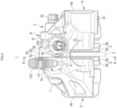
FIG. 1] FIG. 1 is a front view of a disc brake for a vehicle showing an embodiment of the present invention. - [
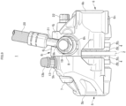
FIG. 2] FIG. 2 is a rear view of the disc brake for a vehicle. - [
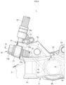
FIG. 3] FIG. 3 is a plan view of the disc brake for a vehicle. - [
FIG. 4] FIG. 4 is a side view of the disc brake for a vehicle. - [
FIG. 5] FIG. 5 is a cross-sectional view taken along a line V-V inFIG. 4 . - [
FIG. 6] FIG. 6 is a cross-sectional view taken along a line VI-VI inFIG. 1 . - [
FIG. 7] FIG. 7 is a cross-sectional view taken along a line VII-VII inFIG. 2 . - [
FIG. 8] FIG. 8 is a front view of main portions in a state in which a union bolt and a hose banjo are attached to a union hole. - [
FIG. 9] FIG. 9 is a side view of the state in which the union bolt and the hose banjo are attached to the union hole. - [
FIG. 10] FIG. 10 is a cross-sectional view taken along a line X-X inFIG. 8 . - [
FIG. 11] FIG. 11 is a front view of a caliper body showing an embodiment of the present invention. - [
FIG. 12] FIG. 12 is a rear view of a caliper half body on an anti-vehicle body-side. - [
FIG. 13] FIG. 13 is a cross-sectional view taken along a line XIII-XIII inFIG. 11 . - [
FIG. 14] FIG. 14 is a front view of the caliper body on a vehicle body-side. - [
FIG. 15] FIG. 15 is a rear view of the caliper half body on the vehicle body-side. - [
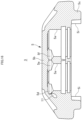
FIG. 16] FIG. 16 is a cross-sectional view taken along a line XVI-XVI inFIG. 15 . -
FIGS. 1 to 16 are views showing an embodiment of a caliper body of a disc brake for a vehicle of the present invention, in which an arrow A indicates a rotation direction of a disc rotor that rotates integrally with wheels when a vehicle moves forward, and a disc outward-rotation-side and a disc inward-rotation-side to be described later are for when the vehicle moves forward. - A
disc brake 1 for a vehicle includes adisc rotor 2 that rotates integrally with wheels (not shown) in an arrow A direction, acaliper body 3 attached to a vehicle body on one side of thedisc rotor 2, and a pair offriction pads caliper body 3 in a manner of facing each other with thedisc rotor 2 interposed therebetween. - The
caliper body 3 is formed by integrally coupling, by twocoupling bolts bridge portion 3a straddling an outer peripheral side of thedisc rotor 2. - The vehicle body-side caliper
half body 5 includes an actingportion 5b havingcylinder holes half body 5c that is substantially half of thebridge portion 3a. Similar to the vehicle body-side caliperhalf body 5, the anti-vehicle body-side caliperhalf body 6 includes an actingportion 6b havingcylinder holes half body 6c that is substantially half of thebridge portion 3a. In addition, a length of the bridgehalf body 6c of the anti-vehicle body-side caliperhalf body 6 in a disc axial direction is larger than a length of the bridgehalf body 5c of the vehicle body-side caliperhalf body 5 in the disc axial direction. When thecaliper body 3 formed by joining thebridge half bodies joint surface 8 is located on a vehicle body-side with respect to a center CL1 in a width direction of thedisc rotor 2. - In the vehicle body-side caliper
half body 5,pistons cylinder holes hydraulic pressure chambers cylinder holes pistons fluid introduction hole 11 is drilled from a dividing surface serving as thejoint surface 8 on the disc outward-rotation-side of thebridge half body 5c toward thehydraulic pressure chamber 10 of thecylinder hole 5a on the disc outward-rotation-side. A part of a bottom of thecylinder hole 5a on the disc outward-rotation-side includes a first contouring processedportion 5d that allows thehydraulic pressure chamber 10 on the disc outward-rotation-side and the first workingfluid introduction hole 11 to communicate with each other by a contouring process, and a second contouring processedportion 5e that is contoured toward thehydraulic pressure chamber 10 on the disc inward-rotation-side. Further, a part of a bottom of thecylinder hole 5a on the disc inward-rotation-side includes a third contouring processedportion 5f that is contoured toward the second contouring processedportion 5e. The second contouring processedportion 5e and the third contouring processedportion 5f communicate with each other, whereby the first workingfluid introduction hole 11, thehydraulic pressure chamber 10 on the disc outward-rotation-side, and thehydraulic pressure chamber 10 on the disc inward-rotation-side communicate with one another. - A
bleeder hole 12 that opens to a disc radial directionouter end surface 5g and communicates with the first workingfluid introduction hole 11 is provided on a disc radial direction outer end on the disc outward-rotation-side of the bridgehalf body 5c. Thebleeder hole 12 is formed with, on an opening side, afemale screw portion 12a into which ableeder screw 13 is screwed, and the disc radial directionouter end surface 5g on an opening outer periphery is formed with amounting seat surface 5h for thebleeder screw 13. Thebleeder screw 13 includes an air discharge hole on an inner peripheral portion thereof and amale screw portion 13a, which is screwed into thefemale screw portion 12a, on an outer peripheral portion thereof, and arubber bleeder cap 13b is covered on a tip head portion. - Similar to the vehicle body-side caliper
half body 5, in the anti-vehicle body-side caliperhalf body 6,pistons cylinder holes hydraulic pressure chambers cylinder holes pistons fluid introduction hole 16 is drilled from a dividing surface serving as thejoint surface 8 on the disc outward-rotation-side of thebridge half body 6c toward thehydraulic pressure chamber 15 on the disc outward-rotation-side. The first workingfluid introduction hole 11 and the second workingfluid introduction hole 16 communicate with each other at thejoint surface 8, and aseal member 17 is interposed on an outer peripheral side of a communication portion. A part of a bottom of thecylinder hole 6a on the disc outward-rotation-side includes a fourth contouring processedportion 6d that allows thehydraulic pressure chamber 15 on the disc outward-rotation-side and the second workingfluid introduction hole 16 to communicate with each other by a contouring process, and a fifth contouring processedportion 6e that is contoured toward thehydraulic pressure chamber 15 on the disc inward-rotation-side. Further, a part of a bottom of thecylinder hole 6a on the disc inward-rotation-side includes a sixth contouring processedportion 6f that is contoured toward the fifth contouring processedportion 6e. The fifth contouring processedportion 6e and the sixth contouring processedportion 6f communicate with each other, whereby the second workingfluid introduction hole 16, thehydraulic pressure chamber 15 on the disc outward-rotation-side, and thehydraulic pressure chamber 15 on the disc inward-rotation-side communicate with one another. - Further, a
union hole 18 that opens to a disc outward-rotation-side end surface 6g and communicates with the second workingfluid introduction hole 16 is provided on a disc outward-rotation-side end of thebridge half body 6c. Theunion hole 18 is formed with, on an opening side, afemale screw portion 18a into which aunion bolt 19 is screwed, and the disc outward-rotation-side end surface 6g on an opening outer periphery is formed with a mountingseat surface 6h for theunion bolt 19. Ahose banjo 21 fixed to an end of abrake hose 20 is attached to theunion bolt 19, and a rotation-stop portion 6i for thehose banjo 21 is formed on an outer periphery of the mountingseat surface 6h. The rotation-stop portion 6i includes awall portion 6j that protrudes from an outer peripheral side of the mountingseat surface 6h and protects the coupling between theunion bolt 19 and thehose banjo 21, and an engagingportion 6k obtained by cutting out a part of thewall portion 6j to stop rotation of thehose banjo 21. Thehose banjo 21 is not co-rotated when theunion bolt 19 is screwed into theunion hole 18 by clamping thehose banjo 21 with the engagingportion 6k. Theunion bolt 19 includes amale screw portion 19a that is screwed into thefemale screw portion 18a and ahexagonal head portion 19b, afluid communication hole 19c is formed inside themale screw portion 19a, and thebrake hose 20 communicates with theunion hole 18 via theunion bolt 19. - Radial mount-type vehicle
body mounting portions bolt insertion holes caliper half body 6, and thecaliper body 3 is attached to the vehicle body by screwing mounting bolts inserted into the mountingbolt insertion holes - In the
caliper body 3, the vehicle body-sidecaliper half body 5 and the anti-vehicle body-sidecaliper half body 6 formed in this manner are joined by thebridge portion 3a and coupled by thecoupling bolts fluid introduction hole 11 and the second workingfluid introduction hole 16 communicate with each other, and accordingly, the first workingfluid introduction hole 11, the second workingfluid introduction hole 16, thehydraulic pressure chambers caliper half body 5, and thehydraulic pressure chambers caliper half body 6 communicate with each other. Further, theunion hole 18 communicates with the second workingfluid introduction hole 16, and thus a working fluid is supplied to thehydraulic pressure chambers union bolt 19, the first workingfluid introduction hole 11, and the second workingfluid introduction hole 16. In addition, thebleeder hole 12 communicates with the first workingfluid introduction hole 11, and thus air mixed in the working fluid introduced into the first workingfluid introduction hole 11, the second workingfluid introduction hole 16, and thehydraulic pressure chambers bleeder screw 13. - Each of the
friction pads 4 includes alining 4a which is in sliding contact with a side surface of thedisc rotor 2, and a metal backplate 4b to which thelining 4a is adhered. A hangingpiece 4c extends from an upper center of theback plate 4b, and ahanger pin 22 is inserted into the hangingpiece 4c. Thehanger pin 22 extends across both the actingportions ceiling opening 3b formed in thebridge portion 3a of thecaliper body 3, and is movable in the disc axial direction betweentorque receiving portions caliper half body 5 and the anti-vehicle body-sidecaliper half body 6. In addition, apad spring 23 is provided over theback plate 4b, thebridge portion 3a, and thehanger pin 22, and thefriction pads - Since the
caliper body 3 of the present embodiment is formed as described above, theunion hole 18 and thebleeder hole 12 can be provided on the vehicle body-sidecaliper half body 5 and the anti-vehicle body-sidecaliper half body 6 without forming a union boss portion and a bleeder boss portion, and the mountingseat surfaces bleeder screw 13 and theunion bolt 19 can be prevented from protruding outward from the vehicle body-sidecaliper half body 5 and the anti-vehicle body-sidecaliper half body 6. Accordingly, it is possible to decrease thecaliper body 3 in size, and further, it is possible to prevent a tip end side of theunion bolt 19 and a tip end side of thebleeder screw 13 from largely protruding outward from thecaliper body 3, and thus it is possible to improve assembly characteristics. - The length of the
bridge half body 6c of the anti-vehicle body-sidecaliper half body 6 in the disc axial direction is larger than the length of thebridge half body 5c of the vehicle body-sidecaliper half body 5 in the disc axial direction, theunion hole 18 that opens to the disc outward-rotation-side end surface 6g is provided on the disc outward-rotation-side end of thebridge half body 6c of the anti-vehicle body-sidecaliper half body 6, and the rotation-stop portion 6i for thehose banjo 21 is formed on the outer periphery of the mountingseat surface 6h, and thus it is possible to secure a space necessary for forming the rotation-stop portion 6i. Accordingly, it is possible to secure a wall thickness of the rotation-stop portion 6i and to improve a formability and a degree of freedom of a shape of the rotation-stop portion 6i. Further, thebleeder hole 12 is processed into the disc radial directionouter end surface 5g of thebridge half body 5c on the disc outward-rotation-side of the vehicle body-sidecaliper half body 5, and thus when thecaliper body 3 is assembled to the vehicle body, it is possible to prevent a tool from interfering with theunion bolt 19 and thebleeder screw 13, thereby improving the assembly characteristics. - In addition, when the
caliper body 3 is attached to the vehicle body with theunion hole 18 facing upward of the vehicle body, a hose length of thebrake hose 20 can be reduced as compared with a case in which a union hole is provided at a center of a bridge portion in the related art. - A part of the bottoms of the
cylinder holes fluid introduction hole 11, and a part of the bottoms of thecylinder holes fluid introduction hole 16, and thus thehydraulic pressure chambers fluid introduction hole 11 can easily and favorably communicate with each other, and thehydraulic pressure chambers fluid introduction hole 16 can easily and favorably communicate with each other. Further, a part of the bottoms of theadjacent cylinder holes adjacent cylinder holes adjacent cylinder holes adjacent cylinder holes cylinder holes - The present invention is not limited to the above-described embodiment, and the union hole may be formed in the bridge half body of the vehicle body-side caliper half body, and the bleeder hole may be formed in the bridge half body of the anti-vehicle body-side caliper half body. The joint surface joining the vehicle body-side caliper half body and the anti-vehicle body-side caliper half body may be located at the center in the width direction of the disc rotor when the caliper body is assembled to the vehicle body. Further, the communication between the cylinder hole and the working fluid introduction hole and the communication between the adjacent cylinder holes are not limited to those in which the communication is performed by a contouring process, and the communication may be performed by a plunge processing or by casting. The vehicle body mounting portion formed in the anti-vehicle body-outer side caliper half body may be an axial mount-type vehicle body mounting portion having a mounting bolt insertion hole in the disc axial direction. Further, the number of cylinder holes formed in the caliper half body is any number.
- 1: disc brake for vehicle; 2: disc rotor; 3: caliper body; 3a: bridge portion; 3b: ceiling opening; 4: friction pad; 4a: lining; 4b: back plate, 5: vehicle body-side caliper half body; 5a: cylinder hole; 5b: acting portion; 5c: bridge half body; 5d: first contouring processed portion; 5e: second contouring processed portion; 5f: third contouring processed portion; 5g: disc radial direction outer end surface; 5h: mounting seat surface; 5i: torque receiving portion; 6: anti-vehicle body-side caliper half body; 6a: cylinder hole; 6b: acting portion; 6c: bridge half body; 6d: fourth contouring processed portion; 6e: fifth contouring processed portion; 6f: sixth contouring processed portion; 6g: disc outward-rotation-side end surface; 6h: mounting seat surface; 6i: rotation-stop portion; 6j: wall portion; 6k: engaging portion; 6m: mounting bolt insertion hole; 6n: vehicle body mounting portion; 6p: torque receiving portion; 7: coupling bolt; 8: joint surface; 9: piston; 10: hydraulic pressure chamber; 11: first working fluid introduction hole; 12: bleeder hole; 12a: female screw portion; 13: bleeder screw; 13a: male screw portion; 13b: bleeder cap; 14: piston; 15: hydraulic pressure chamber; 16: second working fluid introduction hole; 17: seal member; 18: union hole; 18a: female screw portion; 19: union bolt; 19a: male screw portion; 19b: hexagonal head portion; 19c: fluid communication hole; 20: brake hose; 21: hose banjo; 22: hanger pin; 23: pad spring
Claims (6)
- A caliper body of a disc brake for a vehicle in which a pair of caliper half bodies arranged on both sides of a disc rotor, each of the pair of caliper half bodies including an acting portion having a cylinder hole and a bridge half body straddling an outer peripheral side of the disc rotor, are joined by matching the bridge half bodies, the caliper body of a disc brake for a vehicle comprising:a union hole configured to allow a working fluid to be introduced;a working fluid introduction hole allowing the union hole to communicate with the cylinder hole and configured to allow the working fluid to be introduced into the cylinder hole; anda bleeder hole configured to allow air mixed in the working fluid to be discharged, whereinthe union hole opens to a disc outward-rotation-side of any one of the bridge half bodies when a vehicle moves forward, and a mounting seat surface for a union bolt to be attached to the union hole is formed on an opening outer periphery of the union hole, andthe bleeder hole opens to a disc outward-rotation-side of the other bridge half body when the vehicle moves forward, and a mounting seat surface for a bleeder screw to be attached to the bleeder hole is formed on an opening outer periphery of the bleeder hole.
- The caliper body of a disc brake for a vehicle according to claim 1, wherein
the union hole opens to a disc outward-rotation-side end surface of the bridge half body, and the bleeder hole opens to a disc radial direction outer end surface on the disc outward-rotation-side of the bridge half body. - The caliper body of a disc brake for a vehicle according to claim 1, wherein
the bleeder hole opens to a disc outward-rotation-side end surface of the bridge half body, and the union hole opens to a disc radial direction outer end surface on the disc outward-rotation-side of the bridge half body. - The caliper body of a disc brake for a vehicle according to any one of claims 1 to 3, whereina joint surface joining the pair of caliper half bodies is located on a vehicle body-side with respect to a center in a width direction of the disc rotor when the caliper body is assembled to a vehicle body,the union hole is formed on the disc outward-rotation-side of the caliper half body disposed on an anti-vehicle body-side, anda rotation-stop portion configured to stop rotation of a hose banjo of a brake hose end to be connected to the union hole protrudes from an outer periphery of the mounting seat surface for the union bolt.
- The caliper body of a disc brake for a vehicle according to any one of claims 1 to 4, wherein
a contouring processed portion obtained by contouring a bottom side of the cylinder hole to allow the bottom side to communicate with the working fluid introduction hole is provided on the bottom side. - The caliper body of a disc brake for a vehicle according to any one of claims 1 to 5, wherein
the caliper half body disposed on an anti-vehicle body-side is provided with a radial mount-type vehicle body mounting portion having a mounting bolt insertion hole in a disc radial direction.
Applications Claiming Priority (2)
| Application Number | Priority Date | Filing Date | Title |
|---|---|---|---|
| JP2020197009 | 2020-11-27 | ||
| PCT/JP2021/043283 WO2022114085A1 (en) | 2020-11-27 | 2021-11-25 | Caliper body of disc brake for vehicle |
Publications (3)
| Publication Number | Publication Date |
|---|---|
| EP4253176A1 true EP4253176A1 (en) | 2023-10-04 |
| EP4253176A4 EP4253176A4 (en) | 2024-11-06 |
| EP4253176B1 EP4253176B1 (en) | 2026-03-25 |
Family
ID=81754343
Family Applications (1)
| Application Number | Title | Priority Date | Filing Date |
|---|---|---|---|
| EP21898057.1A Active EP4253176B1 (en) | 2020-11-27 | 2021-11-25 | Caliper body of disc brake for vehicle |
Country Status (4)
| Country | Link |
|---|---|
| EP (1) | EP4253176B1 (en) |
| JP (1) | JP7595086B2 (en) |
| CN (1) | CN116568575A (en) |
| WO (1) | WO2022114085A1 (en) |
Cited By (2)
| Publication number | Priority date | Publication date | Assignee | Title |
|---|---|---|---|---|
| EP4105512A4 (en) * | 2020-02-12 | 2024-03-20 | Hitachi Astemo, Ltd. | VEHICLE DISC BRAKE |
| WO2025194207A1 (en) * | 2024-03-18 | 2025-09-25 | Advanced Braking Pty Ltd | Brake calliper |
Families Citing this family (1)
| Publication number | Priority date | Publication date | Assignee | Title |
|---|---|---|---|---|
| KR20230152379A (en) * | 2022-04-27 | 2023-11-03 | 현대모비스 주식회사 | Brake apparatus for vehicle |
Family Cites Families (12)
| Publication number | Priority date | Publication date | Assignee | Title |
|---|---|---|---|---|
| JP3344729B2 (en) * | 1991-01-17 | 2002-11-18 | トキコ株式会社 | Disc brake |
| JPH06330964A (en) * | 1993-05-19 | 1994-11-29 | Nissin Kogyo Kk | Opposing piston type caliper of disc brake |
| JP3097012B2 (en) * | 1993-06-15 | 2000-10-10 | 日信工業株式会社 | Holding structure of lead wire for wear indicator of hydraulic brake disc for vehicle |
| JP3271034B2 (en) * | 1993-11-22 | 2002-04-02 | 日信工業株式会社 | Caliper body of vehicle disc brake |
| JP3729613B2 (en) * | 1997-08-11 | 2005-12-21 | 日信工業株式会社 | Vehicle disc brake |
| JP4183956B2 (en) * | 2002-03-14 | 2008-11-19 | 株式会社日立製作所 | Disc brake |
| JP3863870B2 (en) * | 2003-08-22 | 2006-12-27 | 日信工業株式会社 | Split caliper body for vehicle disc brakes |
| JP2006105326A (en) * | 2004-10-07 | 2006-04-20 | Nissin Kogyo Co Ltd | Vehicle disc brake |
| JP4767889B2 (en) * | 2007-03-27 | 2011-09-07 | 本田技研工業株式会社 | Vehicle disc brake |
| JP4866873B2 (en) * | 2008-04-18 | 2012-02-01 | 日信工業株式会社 | Vehicle disc brake |
| JP4892571B2 (en) * | 2009-02-12 | 2012-03-07 | 日信工業株式会社 | Caliper body for disc brakes for vehicles |
| WO2021161642A1 (en) * | 2020-02-12 | 2021-08-19 | 日立Astemo株式会社 | Vehicle disc brake |
-
2021
- 2021-11-25 EP EP21898057.1A patent/EP4253176B1/en active Active
- 2021-11-25 JP JP2022565424A patent/JP7595086B2/en active Active
- 2021-11-25 WO PCT/JP2021/043283 patent/WO2022114085A1/en not_active Ceased
- 2021-11-25 CN CN202180079807.7A patent/CN116568575A/en active Pending
Cited By (2)
| Publication number | Priority date | Publication date | Assignee | Title |
|---|---|---|---|---|
| EP4105512A4 (en) * | 2020-02-12 | 2024-03-20 | Hitachi Astemo, Ltd. | VEHICLE DISC BRAKE |
| WO2025194207A1 (en) * | 2024-03-18 | 2025-09-25 | Advanced Braking Pty Ltd | Brake calliper |
Also Published As
| Publication number | Publication date |
|---|---|
| EP4253176B1 (en) | 2026-03-25 |
| CN116568575A (en) | 2023-08-08 |
| WO2022114085A1 (en) | 2022-06-02 |
| JP7595086B2 (en) | 2024-12-05 |
| EP4253176A4 (en) | 2024-11-06 |
| JPWO2022114085A1 (en) | 2022-06-02 |
Similar Documents
| Publication | Publication Date | Title |
|---|---|---|
| EP4253176A1 (en) | Caliper body of disc brake for vehicle | |
| EP4105512B1 (en) | Vehicle disc brake | |
| EP0087876B1 (en) | Disc brake caliper assembly | |
| US6269734B1 (en) | Piston for a hydraulic piston cylinder unit | |
| JP4783822B2 (en) | Caliper body for disc brakes for vehicles | |
| US11320011B2 (en) | Caliper for opposed piston-type disc brake | |
| EP4260964B1 (en) | Method for producing caliper half body of disc brake caliper body, caliper half body of disc brake caliper body, and method for providing disc brake caliper body | |
| EP4265935B1 (en) | Caliper body for vehicular disc brake | |
| JP4169685B2 (en) | Caliper body for vehicle disc brake | |
| EP4397883A1 (en) | Caliper body for vehicular disc brake | |
| JPH07317816A (en) | Vehicle disc brake bracket shim integrated pad retainer | |
| EP4397882A1 (en) | Disc brake and friction pad for vehicle | |
| JP3863870B2 (en) | Split caliper body for vehicle disc brakes | |
| JP7312797B2 (en) | Caliper body for vehicle disc brakes | |
| EP4036431B1 (en) | Caliper body for vehicular disc brake | |
| JP4295890B2 (en) | Caliper body for disc brakes for vehicles | |
| JP5562294B2 (en) | Vehicle disc brake | |
| JP4495633B2 (en) | Vehicle disc brake | |
| JP3507972B2 (en) | Divided caliper body for vehicle disc brake | |
| JP2012167724A (en) | Vehicular disk brake | |
| JP2021156368A (en) | Caliper body of disc brake for vehicle | |
| JPH07145836A (en) | Caliper body for vehicle disc brakes | |
| JP2005282717A (en) | Disk brake for vehicle | |
| JP2005344839A (en) | Pin slide type vehicle disc brake | |
| JP2006029550A (en) | Caliper body for disc brake for pin slide type vehicle |
Legal Events
| Date | Code | Title | Description |
|---|---|---|---|
| STAA | Information on the status of an ep patent application or granted ep patent |
Free format text: STATUS: THE INTERNATIONAL PUBLICATION HAS BEEN MADE |
|
| PUAI | Public reference made under article 153(3) epc to a published international application that has entered the european phase |
Free format text: ORIGINAL CODE: 0009012 |
|
| STAA | Information on the status of an ep patent application or granted ep patent |
Free format text: STATUS: REQUEST FOR EXAMINATION WAS MADE |
|
| 17P | Request for examination filed |
Effective date: 20230526 |
|
| AK | Designated contracting states |
Kind code of ref document: A1 Designated state(s): AL AT BE BG CH CY CZ DE DK EE ES FI FR GB GR HR HU IE IS IT LI LT LU LV MC MK MT NL NO PL PT RO RS SE SI SK SM TR |
|
| DAV | Request for validation of the european patent (deleted) | ||
| DAX | Request for extension of the european patent (deleted) | ||
| A4 | Supplementary search report drawn up and despatched |
Effective date: 20241004 |
|
| RIC1 | Information provided on ipc code assigned before grant |
Ipc: F16D 55/228 20060101ALI20240927BHEP Ipc: F16D 65/02 20060101ALI20240927BHEP Ipc: B60T 17/00 20060101AFI20240927BHEP |
|
| STAA | Information on the status of an ep patent application or granted ep patent |
Free format text: STATUS: EXAMINATION IS IN PROGRESS |
|
| 17Q | First examination report despatched |
Effective date: 20250624 |
|
| RAP3 | Party data changed (applicant data changed or rights of an application transferred) |
Owner name: ASTEMO, LTD. |
|
| GRAP | Despatch of communication of intention to grant a patent |
Free format text: ORIGINAL CODE: EPIDOSNIGR1 |
|
| STAA | Information on the status of an ep patent application or granted ep patent |
Free format text: STATUS: GRANT OF PATENT IS INTENDED |
|
| INTG | Intention to grant announced |
Effective date: 20251124 |
|
| GRAS | Grant fee paid |
Free format text: ORIGINAL CODE: EPIDOSNIGR3 |
|
| GRAA | (expected) grant |
Free format text: ORIGINAL CODE: 0009210 |
|
| STAA | Information on the status of an ep patent application or granted ep patent |
Free format text: STATUS: THE PATENT HAS BEEN GRANTED |
|
| AK | Designated contracting states |
Kind code of ref document: B1 Designated state(s): AL AT BE BG CH CY CZ DE DK EE ES FI FR GB GR HR HU IE IS IT LI LT LU LV MC MK MT NL NO PL PT RO RS SE SI SK SM TR |
|
| REG | Reference to a national code |
Ref country code: CH Ref legal event code: F10 Free format text: ST27 STATUS EVENT CODE: U-0-0-F10-F00 (AS PROVIDED BY THE NATIONAL OFFICE) Effective date: 20260325 Ref country code: GB Ref legal event code: FG4D |
|
| REG | Reference to a national code |
Ref country code: DE Ref legal event code: R096 Ref document number: 602021050851 Country of ref document: DE |
|
| REG | Reference to a national code |
Ref country code: IE Ref legal event code: FG4D |