EP4253160A1 - Display device and ship - Google Patents
Display device and ship Download PDFInfo
- Publication number
- EP4253160A1 EP4253160A1 EP21897728.8A EP21897728A EP4253160A1 EP 4253160 A1 EP4253160 A1 EP 4253160A1 EP 21897728 A EP21897728 A EP 21897728A EP 4253160 A1 EP4253160 A1 EP 4253160A1
- Authority
- EP
- European Patent Office
- Prior art keywords
- mode
- screen
- display
- symbol
- section
- Prior art date
- Legal status (The legal status is an assumption and is not a legal conclusion. Google has not performed a legal analysis and makes no representation as to the accuracy of the status listed.)
- Pending
Links
Images


Classifications
-
- B—PERFORMING OPERATIONS; TRANSPORTING
- B63—SHIPS OR OTHER WATERBORNE VESSELS; RELATED EQUIPMENT
- B63B—SHIPS OR OTHER WATERBORNE VESSELS; EQUIPMENT FOR SHIPPING
- B63B49/00—Arrangements of nautical instruments or navigational aids
-
- B—PERFORMING OPERATIONS; TRANSPORTING
- B63—SHIPS OR OTHER WATERBORNE VESSELS; RELATED EQUIPMENT
- B63H—MARINE PROPULSION OR STEERING
- B63H21/00—Use of propulsion power plant or units on vessels
- B63H21/21—Control means for engine or transmission, specially adapted for use on marine vessels
-
- B—PERFORMING OPERATIONS; TRANSPORTING
- B60—VEHICLES IN GENERAL
- B60K—ARRANGEMENT OR MOUNTING OF PROPULSION UNITS OR OF TRANSMISSIONS IN VEHICLES; ARRANGEMENT OR MOUNTING OF PLURAL DIVERSE PRIME-MOVERS IN VEHICLES; AUXILIARY DRIVES FOR VEHICLES; INSTRUMENTATION OR DASHBOARDS FOR VEHICLES; ARRANGEMENTS IN CONNECTION WITH COOLING, AIR INTAKE, GAS EXHAUST OR FUEL SUPPLY OF PROPULSION UNITS IN VEHICLES
- B60K35/00—Instruments specially adapted for vehicles; Arrangement of instruments in or on vehicles
- B60K35/20—Output arrangements, i.e. from vehicle to user, associated with vehicle functions or specially adapted therefor
- B60K35/21—Output arrangements, i.e. from vehicle to user, associated with vehicle functions or specially adapted therefor using visual output, e.g. blinking lights or matrix displays
-
- B—PERFORMING OPERATIONS; TRANSPORTING
- B63—SHIPS OR OTHER WATERBORNE VESSELS; RELATED EQUIPMENT
- B63H—MARINE PROPULSION OR STEERING
- B63H21/00—Use of propulsion power plant or units on vessels
- B63H21/20—Use of propulsion power plant or units on vessels the vessels being powered by combinations of different types of propulsion units
-
- G—PHYSICS
- G06—COMPUTING OR CALCULATING; COUNTING
- G06F—ELECTRIC DIGITAL DATA PROCESSING
- G06F3/00—Input arrangements for transferring data to be processed into a form capable of being handled by the computer; Output arrangements for transferring data from processing unit to output unit, e.g. interface arrangements
- G06F3/01—Input arrangements or combined input and output arrangements for interaction between user and computer
- G06F3/03—Arrangements for converting the position or the displacement of a member into a coded form
- G06F3/041—Digitisers, e.g. for touch screens or touch pads, characterised by the transducing means
- G06F3/0412—Digitisers structurally integrated in a display
-
- G—PHYSICS
- G06—COMPUTING OR CALCULATING; COUNTING
- G06F—ELECTRIC DIGITAL DATA PROCESSING
- G06F3/00—Input arrangements for transferring data to be processed into a form capable of being handled by the computer; Output arrangements for transferring data from processing unit to output unit, e.g. interface arrangements
- G06F3/01—Input arrangements or combined input and output arrangements for interaction between user and computer
- G06F3/048—Interaction techniques based on graphical user interfaces [GUI]
- G06F3/0481—Interaction techniques based on graphical user interfaces [GUI] based on specific properties of the displayed interaction object or a metaphor-based environment, e.g. interaction with desktop elements like windows or icons, or assisted by a cursor's changing behaviour or appearance
- G06F3/04817—Interaction techniques based on graphical user interfaces [GUI] based on specific properties of the displayed interaction object or a metaphor-based environment, e.g. interaction with desktop elements like windows or icons, or assisted by a cursor's changing behaviour or appearance using icons
-
- B—PERFORMING OPERATIONS; TRANSPORTING
- B60—VEHICLES IN GENERAL
- B60K—ARRANGEMENT OR MOUNTING OF PROPULSION UNITS OR OF TRANSMISSIONS IN VEHICLES; ARRANGEMENT OR MOUNTING OF PLURAL DIVERSE PRIME-MOVERS IN VEHICLES; AUXILIARY DRIVES FOR VEHICLES; INSTRUMENTATION OR DASHBOARDS FOR VEHICLES; ARRANGEMENTS IN CONNECTION WITH COOLING, AIR INTAKE, GAS EXHAUST OR FUEL SUPPLY OF PROPULSION UNITS IN VEHICLES
- B60K2360/00—Indexing scheme associated with groups B60K35/00 or B60K37/00 relating to details of instruments or dashboards
- B60K2360/16—Type of output information
- B60K2360/172—Driving mode indication
-
- B—PERFORMING OPERATIONS; TRANSPORTING
- B63—SHIPS OR OTHER WATERBORNE VESSELS; RELATED EQUIPMENT
- B63H—MARINE PROPULSION OR STEERING
- B63H21/00—Use of propulsion power plant or units on vessels
- B63H21/20—Use of propulsion power plant or units on vessels the vessels being powered by combinations of different types of propulsion units
- B63H2021/202—Use of propulsion power plant or units on vessels the vessels being powered by combinations of different types of propulsion units of hybrid electric type
- B63H2021/205—Use of propulsion power plant or units on vessels the vessels being powered by combinations of different types of propulsion units of hybrid electric type the second power unit being of the internal combustion engine type, or the like, e.g. a Diesel engine
-
- G—PHYSICS
- G06—COMPUTING OR CALCULATING; COUNTING
- G06F—ELECTRIC DIGITAL DATA PROCESSING
- G06F2203/00—Indexing scheme relating to G06F3/00 - G06F3/048
- G06F2203/041—Indexing scheme relating to G06F3/041 - G06F3/045
Definitions
- the present invention relates to a ship-dedicated display device.
- Operating state of the ship-dedicated hybrid system includes, for example, a status in which a propelling machine of the ship is driven by one or both of the engine and the motor, a status in which the the engine causes the motor to generate electricity, and a status in which the motor regenerates a kinetic energy of the ship.
- Patent Literature 1 Japanese Patent No. 3708925
- An exemplary display device is a display device for displaying an operating state of a hybrid system that drives a propelling machine which propels a ship, a display screen for displaying the operating state including: a symbol that represents a constituent element included in the hybrid system; and a linear section that connects between a plurality of the symbols, and that, according to an operating mode of the hybrid system, changes an illumination state.
- a crew in a ship provided with a hybrid system, can easily grasp an operating state of a hybrid system.
- FIG. 1 is a schematic view of a configuration of a ship-dedicated hybrid system 100 according to an embodiment of the present invention.
- the hybrid system 100 is provided on a ship.
- the hybrid system 100 drives a propelling machine 101 that propels the ship.
- the propelling machine 101 is a propeller.
- the hybrid system 100 is provided with an engine 102, a motor 103, and a power transmission device 104.
- the engine 102 and the motor 103 are drive sources for rotating the propelling machine 101.
- Th engine 102 is a known ship-dedicated diesel engine.
- the engine 102 serves as a main machine.
- the engine 102 is provided with a crankshaft 102a that receives a reciprocating motion of an unshown piston and performs a revolution motion.
- the crankshaft 102a is an output shaft of the engine 102.
- the motor 103 is connected to a battery 105.
- the electric power stored in the battery 105 is supplied to the motor 103, making it possible to rotationally drive a motor output shaft 103a which is an output of the motor 103. Further, rotating the motor output shaft 103a with an outer force causes the motor 103 to function as a generator, making it possible to charge the battery 105.
- the power transmission device 104 is provided with a power transmission shaft and clutch which are not shown. Switching the clutch in the power transmission device 104 can switch the power transmission to a plurality of types of statuses. In the present embodiment, switching the clutch of the power transmission device 104 can make a switching among a status in which only a drive force of the engine 102 is transmitted to the propelling machine 101, a status in which only a drive force of the motor 103 is transmitted to the propelling machine 101, a status in which the drive forces of the engine 102 and motor 103 in combination are transmitted to the propelling machine 101. Further, the power transmission device 104, by switching the clutch, can obtain a status in which the power of the engine 102 is transmitted to the motor output shaft 103a.
- FIG. 2 is a block diagram showing an electrical configuration of the ship-dedicated hybrid system 100 according to the embodiment of the present invention.
- the hybrid system 100 includes an engine ECU (Electronic Control Unit) 111, a drive ECU 112, a helm ECU 113, an inverter 114, a BMS (Battery Management System) 115, a Hybrid ECU 116, and a display device 1.
- ECU Electronic Control Unit
- a drive ECU 112 a helm ECU 113
- an inverter 114 a BMS (Battery Management System) 115
- Hybrid ECU 116 Hybrid ECU
- the communication bus 117 is, for example, a CAN (Controller Area Network) bus.
- the engine ECU 111 controls the engine 102.
- the drive ECU 112 controls the power transmission device 104.
- the helm ECU 113 manages the user's ship-operation information, such as a shift lever and a throttle lever.
- the inverter 114 is an inverter for drive control of the motor 103.
- the BMS 115 manages the battery 105.
- the BMS 115 for example, monitors the current, voltage, and temperature of the battery 105, and grasps the status of charge (SOC; Status of Charge).
- the hybrid ECU 116 controls the motor 103 via the inverter 114.
- the hybrid ECU 116 in cooperation with, for example, the engine ECU 111 and drive ECU 112, executes a control related to switching of the operating mode of the hybrid system 100. As described below, there are a plurality of types of operating modes in the hybrid system 100 of the present embodiment.
- the display device 1 displays an operating state of the hybrid system 100.
- the display device 1 receives information from each of the sections 111 to 116 through a CAN communication using the CAN bus 117, thereby to display the operating state of the hybrid system 100. Further, the display device 1 allows the user to switch the operating mode.
- FIG. 3 is a front front view of the configuration of the display device 1 according to the embodiment of the present invention.
- the display device 1 has a display panel 1a and a bezel 1b that covers the outer periphery of the display panel 1a from the front side.
- the display panel 1a is composed of, for example, a liquid crystal panel or an organic EL panel.
- the bezel 1b is frame-shaped in plan view from the front. In plan view from the front of the display device 1, the inside of the bezel 1b is a screen area 10 where the image is displayed.
- the display device 1 is rectangular in plan view from the front.
- the bezel 1b has a rectangular frame shape in plan view from the front.
- the screen area 10 is rectangular in shape. Further, these shapes may be changed as needed. For example, the screen area 10 may be circular, oval, etc. Further, the bezel does not have to be frame-shaped. For example, the bezel may be so configured as to be placed only on the right and left of the display panel 1a in plan view from the front of the display device 1.
- a plurality of mode switch buttons 4 for operating mode switching operations are placed around the screen area 10.
- the mode switch button 4 is exposed on the front side via an opening provided in the bezel 1b.
- One of the mode switch buttons 4 is provided for corresponding each of the operating modes. Further, it may be so configured that switching between the operating modes is performed by using a touch screen. In this case, touching a given position in the screen area 10 switches the operating mode.
- the screen area 10 displays a screen that displays the operating state.
- there are a plurality of types of screens displaying the operating state and the plurality of types of screens displaying the operating state are provided in a switchable manner.
- the types of screens that is switchable by the display device 1 include an aggregate screen that displays the operating state in aggregate, a data list screen that shows detailed information on the operating state, a warning list screen that shows the content of a warning that is occurring, and an error list screen that shows the content of an error that is occurring. Further, the screen shown in FIG. 3 is the aggregate screen.
- the display device 1 is so provided as to be switchable to a screen that shows another operating state different from that of the aggregate screen. This makes it possible for a ship crew to obtain a great deal of information on the operating state of the hybrid system 100.
- the display device 1 is provided with a screen switch button 5 that allows switching between the plurality of types of screens.
- the screen switch button 5, like the mode switch button 4, is placed around the screen area 10. Further, it may be so configured that switching among the plurality of types of screens is performed by using the touch screen. In this case, touching the given position in the screen area 10 switches the screen.
- the display device 1 is provided with a close button 6.
- the close button 6 like the mode switch button 4 and the screen switch button 5, is also placed around the screen area 10. Details of the close button 6 are described below.
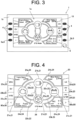
- FIG. 4 is a schematic view of a configuration of the aggregate screen 20 which displays the operating state in aggregate.
- the aggregate screen 20 is a screen that displays important information to the ship crew, and is a main screen that is mainly used in normal times.
- the aggregate screen 20 is rectangular in shape with a longer right/left direction than an up/down direction.
- a display screen 20 (in detail, the aggregate screen 20) that displays the operating state includes a symbol 21 that represents a constituent element included in the hybrid system 100, and a linear section 22 that connects between the plurality of symbols 21, and that, according to the operating mode of the hybrid system 100, changes an illumination state.
- the ship crew by viewing the aggregate screen 20, can easily grasp the current relation of the plurality of constituent elements included in the hybrid system 100.
- the propelling machine 101 is a constituent element included in the hybrid system 100.
- the plurality of symbols 21 include a symbol 21a representing the engine 102, a symbol 21b representing the motor 103, a symbol 21c representing the battery 105, and a symbol 21d representing the propelling machine 101. According to this, viewing the aggregate screen 20 makes it easy to grasp the current relation of the main constituent elements included in the hybrid system 100.
- the symbol 21a representing the engine 102 may be expressed by an engine symbol 21a
- the symbol 21b representing the motor 103 may be expressed by a motor symbol 21b
- the symbol 21c representing the battery 105 may be expressed by a battery symbol 21c
- the symbol 21d representing the propelling machine 101 may be expressed by a propelling machine symbol 21d, respectively.
- each of the symbols 21a to 21d may be, for example, a figure, a sign, a letter, a string of letters, a symbol mark, etc.
- each of the symbols 21a to 21d is a figure that combines a symbol mark, which is pronounced of each constituent element, with a circle surrounding the symbol mark.
- the engine symbol 21a is a figure where a symbol mark that is pronounced of an engine is surrounded by a circle.
- the motor symbol 21b is a figure where a symbol mark that is pronounced of a motor is surrounded by a circle.
- the battery symbol 21c is a figure where a symbol mark that is pronounced of a battery is surrounded by a circle.
- the propelling machine symbol 21d is a figure where a symbol mark that is pronounced of a propeller is surrounded by a circle.
- each of the four symbols 21a to 21d is placed at the top section of a rhombus and in the center section of the aggregate screen 20.
- the engine symbol 21a is placed closer to the left than the center position of the aggregate screen 20.
- the motor symbol 21b is positioned above the center position of the aggregate screen 20.
- the battery symbol 21c is placed closer to the right than the center position of the aggregate screen 20.
- the propelling machine symbol 21d is positioned below the center position of the aggregate screen 20.
- the linear section 22 connecting the symbols 21 may include a straight line, a curve, or both the straight line and the curve.
- the linear section 22 includes the curve.
- the plurality of linear sections 22 includes a first linear section 22a, a second linear section 22b, a third linear section 22c, and a fourth linear section 22d.
- the first linear section 22a connects the engine symbol 21a with the motor symbol 21b.
- the second linear section 22b connects the engine symbol 21a with the propelling machine symbol 21d.
- the third linear section 22c connects the motor symbol 21b with the battery symbol 21c.
- the fourth linear section 22d connects the motor symbol 21b with the propelling machine symbol 21d.
- the first linear section 22a and the second linear section 22b each constitute one circular arc section of a circle passing through the engine symbol 21a, the motor symbol 21b, and the propelling machine symbol 21d.
- the third and fourth linear sections 22c and 22d each constitute one circular arc section of a circle passing through the motor symbol 21b, the battery symbol 21c, and propelling machine symbol 21d.
- the aggregate screen 20 includes two additional linear sections 23 that do not change their illumination statuses according to the operating mode of the hybrid system 100.
- the additional linear sections 23 include a first additional linear section 23a connecting the motor symbol 21b with the propelling machine symbol 21d and a second additional linear section 23b connecting the battery symbol 21c with the propelling machine symbol 21d.
- the first additional linear section 23a constitutes the circular arc section of the circle same as the circle of the first linear section 22a and second linear section 22b.
- the second additional linear section 23b constitutes the circular arc section of the circle same as the circle of the third linear section 22c and fourth linear section 22d.
- Providing the additional linear section 23 improves the design property of the aggregate screen 20.
- first additional linear section 23a and the second additional linear section 23b may not be provided.
- first additional linear section 23a may not be an additional linear section, but may be a linear section that changes its illumination state according to the operating mode of the hybrid system 100.
- the aggregate screen 20 further includes status display sections 24 that show the statuses of the constituent elements which correspond to the respective symbols 21a to 21d and which are of the hybrid system 100. This allows the ship crew to know, by the aggregate screen 20, more about details of the statuses of the constituent elements included in the hybrid system 100.
- the status display section 24 includes an engine status display section 24a, a motor status display section 24b, a battery status display section 24c, and a propelling machine status display section 24d.
- the engine status display section 24a shows the status of the engine 102 which is the hybrid system 100's constituent element that corresponds to the engine symbol 21a.
- the motor status display section 24b shows the status of the motor 103 which is the hybrid system 100's constituent element that corresponds to the motor symbol 21b.
- the battery status display section 24c shows the status of the battery 105 which is the hybrid system 100's constituent element that corresponds to the battery symbol 21c.
- the propelling machine status display section 24d shows the status of the propelling machine 101 which is the hybrid system 100's constituent element that corresponds to the propelling machine symbol 21d.
- the four status display sections 24a to 24d are so placed as to surround the four symbols 21a to 24 which are placed in the center section of the aggregate screen 20.
- the engine status display section 24a has a character section that displays the revolution speed of the engine 102, and a surrounding linear section that surrounds the character section.
- the engine status display section 24a is placed near the engine symbol 21a.
- the engine status display section 24a is placed in the upper left section of the aggregate screen 20.
- the display content of the engine status may include an engine status, other than the engine speed, such as engine temperature, for example.
- the motor status display section 24b has a character section that displays the rotation speed of the motor 103, and a surrounding linear section that surrounds the character section.
- the motor status display section 24b is placed near the motor symbol 21b.
- the motor status display section 24b is placed in the upper right section of the aggregate screen 20. Further, the display content of the motor status may include a motor status, other than motor speed, such as a motor temperature, for example.
- the battery status display section 24c has a character section displaying the current value and SOC of the battery 105, and a surrounding linear section surrounding the character section.
- the battery status display section 24c is placed near the battery symbol 21c.
- the battery status display section 24c is placed in the lower right corner of the aggregate screen 20.
- the display content of the battery status may include a battery status, other than battery current and SOC, such as a battery voltage, for example.
- the propelling machine status display section 24d has a character section that displays the rotation speed of the propelling machine 101 (propeller), and a surrounding linear section that surrounds the character section.
- the propelling machine status display section 24d is placed near the propelling machine symbol 21d.
- the propelling machine status display section 24d is placed in the lower left section of the aggregate screen 20. Further, the display content of the propelling machine status may include a propelling machine status other than the propeller rotation speed.
- the aggregate screen 20 includes an operating mode display section 25 that displays the plurality of types of operating modes provided for the hybrid system 100. This allows the ship crew to easily select, while viewing the aggregate screen 20, the operating mode to be used in the hybrid system 100.
- the operating mode display section 25 includes an ENG display 25a showing "ENG Mode”, an EV display 25b showing “MOT Mode”, an HYB display 25c showing “HYB Mode", an LG display 25d showing "LG Mode”, an HV_A display 25e showing "HYB_A Mode”, and an HV_G/GN display 25f showing "HYB_G Mode” and "HYB_GN Mode”.
- the "ENG Mode” is an operating mode for sailing with the engine 102.
- the “MOT Mode” is an operating mode for sailing with the motor 103.
- the “HYB Mode” is an operating mode in which the sailing with the engine 102 is assisted by the motor 103.
- the LG Mode is an operating mode for charging the battery 105 by using a land-based power source.
- the "HYB_A Mode” is an operating mode in which the sailing with the engine 102 is assisted by the motor 103 more powerfully than in the "HYB Mode”.
- the HYB_G Mode” and the “HYB_GN Mode” are operating modes in which using the engine 102 while sailing charges the battery 105.
- the operating mode display section 25 is placed in the end section of the aggregate screen 20.
- the plurality of buttons 4, which are provided alongside the operating mode display section 25, and which enable a selection of each of the operating modes, are placed around the aggregate screen 20. According to this, use of the plurality of buttons 4 which are independently provided makes it possible to select the operating mode on the ship that is prone to swing, thus making it possible to reduce the possibility of selecting the wrong operating mode. Further, the plurality of buttons 4 are the plurality of mode switch buttons 4 described above.
- the operating mode display section 25 is also displayed on a screen other than the aggregate screen 20.
- the operating mode display section 25 is displayed on all screens. That is, the operating mode display section 25 is also included in the data list screen, the warning list screen, and the error list screen.
- the ENG display 25a, the EV display 25b, and the HYB display 25c which are included in the operating mode display section 25 are placed in the left end section of the aggregate screen 20.
- the ENG display 25a, the EV display 25b, and the HYB display 25c are lined up in this order from upper to lower.
- the mode switch buttons 4 are placed to the left of the ENG display 25a, the EV display 25b, and the HYB display 25c, respectively. Pressing the mode switch button 4 placed to the left of the ENG display 25a selects "ENG Mode”. Pressing the mode switch button 4 placed to the left of the EV display 25b selects "MOT Mode”. Pressing the mode switch button 4 placed to the left of the HYB display 25c selects "HYB Mode".
- the LG display 25d, the HV_A display 25e, and the HV_G/GN display 25f which are included in the operating mode display section 25 are placed in the right end section of the aggregate screen 20. In the right end section, the LG display 25d, the HV_A display 25e, and the HV_G/GN display 25f are lined up in this order from upper to lower.
- the mode switch buttons 4 are placed on the right side of the LG display 25d, the HV_A display 25e, and the HV_G/GN display 25f, respectively. Pressing the mode switch button 4 placed to the right of the LG display 25d selects "LG Mode". Pressing the mode switch button 4 placed to the right of the HV_A display 25e selects "HV_A Mode”. Pressing the mode switch button 4 placed to the right of the HV_G/GN display 25f selects "HV_G Mode".
- the aggregate screen 20 includes a current operating mode display area 26 that shows the currently selected operating mode.
- the current operating mode display area 26 is placed between the battery status display section 24c and the propelling machine status display section 24d in the right/left direction, and below the propelling machine symbol 21d.
- FIG. 4 shows a status in which none of the operating modes displayed in the operating mode display section 25 is selected, and "STB Mode” is displayed in the current operating mode display area 26. "STB Mode” is a standby mode that waits for the selection of the operating mode.
- FIGS. 5A and 5B illustrate a mode transition-underway icon 27. As shown in FIG. 5A , during the transition of the operating mode, the mode transition-underway icon 27 is displayed on the lower side of the current operating mode display area 26. This allows the ship crew to easily recognize that the operating mode is in transition.
- the mode transition-underway icon 27 includes three triangular symbols 27a, 27b, and 27c aligned in the right/left direction.
- the lighting positions of the symbols 27a to 27c change at a given time interval (e.g., 0.5 second, etc.).
- the lighting position changes in the order of the first symbol 27a, the second symbol 27b, and the third symbol 27c; after the third symbol 27c is lit, the lighting position returns to the first symbol 27a. This changing of the lighting position is repeated during the mode transition. This allows the ship crew to more easily recognize that the operating mode is in transition.
- the color of the linear section 22 is different between a first energy flow which shows the flow of an energy for driving the propelling machine 101, and a second energy flow which shows the flow of an energy for charging the battery 105.
- the ship crew by viewing the aggregate screen 20, can immediately recognize the energy flow which accords to the operating mode.
- it is so configured as to display, by color, the difference in the type of an energy flow, but it may also be so configured as to display, by changing the way of lighting (e.g., blinking and non-blinking), the difference in energy flow.
- the following exemplifies the aggregate screen 20 in a plurality of operating modes, showing a detailed description of the energy flow display.
- the background of the aggregate screen 20 is black.
- the color of the linear section 22 is white.
- the color of the linear section 22 which shows the first energy flow is green.
- the color of the linear section 22 which shows the second energy flow is blue.
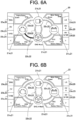
- FIG. 6A is a schematic view of the aggregate screen 20 seen when "ENG Mode” is selected.
- "ENG Mode" the power of the engine 102 is transmitted to the propelling machine 101. That is, the energy for driving the propelling machine 101 flows from the engine 102 to the propelling machine 101.
- the color of the second linear section 22b connecting the engine symbol 21a with the propelling machine symbol 21d is green. Further, the colors of the first linear section 22a, the third linear section 22c, and the fourth linear section 22d are white.
- FIG. 6B is a schematic view of the aggregate screen 20 seen in the case of "ENG_N Mode".
- "ENG_N Mode” is the operating mode seen when "ENG Mode” is selected in the display device 1 and the shift lever is in neutral. In this case, power is not transmitted to the propelling machine 101 even when the engine 102 is in operation. That is, the energy for driving the propelling machine 101 does not flow from the engine 102 to the propelling machine 101.
- the color of the second linear section 22b connecting the engine symbol 21a with the propelling machine symbol 21d like the color of the other linear sections 22a, 22c and 22d, is white.
- FIG. 7A is a schematic view of the aggregate screen 20 seen when "MOT Mode” is selected.
- the motor 103 obtains power from the battery 105 thereby to rotate the motor output shaft 103a, transmitting the rotational power of the motor output shaft 103a to the propelling machine 101. That is, the energy for driving the propelling machine 101 flows from the battery 105 to the motor 103, and then flows from the motor 103 to the propelling machine 101.
- the colors of the third linear section 22c connecting the motor symbol 21b with the battery symbol 21c and of the fourth linear section 22d connecting the motor symbol 21a with the propelling machine symbol 21d are green. Further, the colors of the first linear section 22a and second linear section 22b are white.
- FIG. 7B is a schematic view of the aggregate screen 20 seen in the case of "MOT_N Mode".
- “MOT_N Mode” is the operating mode seen when “MOT Mode” is selected on the display device 1 and the shift lever is in neutral. In this case, power is not transmitted to the propelling machine 101 even when the motor 103 is powered by the battery 105 and is in operation. That is, the energy for driving the propelling machine 101 does not flow from the motor 103 to the propelling machine 101.
- the aggregate screen 20 seen in the case of "MOT_N Mode” only the color of the third linear section 22c connecting the motor symbol 21b with the battery symbol 21c is green, while the colors of the other linear sections 22a, 22b and 22d are white.
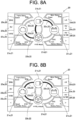
- FIG. 8A is a schematic view of the aggregate screen 20 seen when "HYB Mode" is selected.
- “HYB Mode” the power of the engine 102, in combination with the power of the motor 103, is transmitted to the propelling machine 101. Further, power for driving the motor 103 is supplied from the battery 105 to the motor 103. That is, the energy for driving the propelling machine 101 flows from the engine 102 to the propelling machine 101, and flows from the battery 105 via the motor 103 to the propelling machine 101.
- the colors of the second linear section 22b connecting the engine symbol 21a with the propelling machine symbol 21d, of the third linear section 22c connecting the motor symbol 21b with the battery symbol 21c, and of the fourth linear section 22d connecting the motor symbol 21a with the propelling machine symbol 21d are green. Further, the color of the first linear section 22a is white.
- FIG. 8B is a schematic view of the aggregate screen 20 seen when "HV_A Mode” is selected.
- the motor 103 assists the engine 102, rotating the propelling machine 101.
- the colors of the first linear section 22a connecting the engine symbol 21a with the motor symbol 21b, of the second linear section 22b connecting the engine symbol 21a with the propelling machine symbol 21d, and of the third linear section 22c connecting the motor symbol 21b with the battery symbol 21c are green. Further, the color of the fourth linear section 22d is white.
- FIG. 9A is a schematic view of the aggregate screen 20 seen when "HV_G Mode" is selected.
- “HV_G Mode” the power of the engine 102 is transmitted to the propelling machine 101. Further, the power of engine 102 rotates the motor output shaft 103a of the motor 103, charging, to the battery 105, the electric power generated by the motor 103. That is, the energy for driving the propelling machine 101 flows from the engine 102 to the propelling machine 101. Further, the energy for charging the battery 105 flows from the engine 102 via the motor 103 to the battery 105.
- the color of the second linear section 22b connecting the engine symbol 21a with the propelling machine symbol 21d is green.
- the colors of the first linear section 22a connecting the engine symbol 21a with the motor symbol 21b, and of the third linear section 22c connecting the motor symbol 21b with the battery symbol 21c are blue. Further, the color of the fourth linear section 22d is white.
- FIG. 9B is a schematic view of the aggregate screen 20 seen when "HV_GN Mode".
- "HV_GN Mode” is the operating mode seen when "HV_G Mode” is selected on the display device 1 and the shift lever is in neutral.
- power is not transmitted from the engine 102 to the propelling machine 101.
- power is transmitted from the engine 102 to the motor 103, charging the battery 105 by the electricity generated by the motor 103. That is, the energy for driving the propelling machine 101 does not flow from the engine 102 and the motor 103 to the propelling machine 101.
- Energy for charging the battery 105 flows from the engine 102 via the motor 103 to the battery 105.
- the color of the second linear section 22b connecting the engine symbol 21a with the propelling machine symbol 21d is white instead of green. Further, the colors of the first linear section 22a connecting the engine symbol 21a with the motor symbol 21b, and of the third linear section 22c connecting the motor symbol 21b with the battery symbol 21c are blue. Further, the color of the fourth linear section 22d is white.
- LG Mode there is no energy flow for driving the propelling machine 101. Further, although there is the energy flow for charging the battery 105, it is so configured as to charge the battery 105 from the land-based power source, and the energy flow cannot be expressed by the linear sections 22a to 22d of the aggregate screen 20. Thus, on the aggregate screen 20 seen in the case of "LG Mode", any of the linear sections 22a to 22d is white.
- the display device 1 is so provided that the aggregate screen 20 is capable of displaying an icon 60 that makes a notification about at least one of the warning and error which are occurring to the hybrid system 100 at present. Creating the above configuration allows the ship crew to quickly recognize the warning or the error occurring to the hybrid system 100. Further, in the present embodiment, the icon 60 is displayed not only on the aggregate screen 20, but also on the data list screen, the warning list screen, and the error list screen.
- the warning is issued when the hybrid system 100 is not currently experiencing the error, but may do so in the future.
- the situation of causing the warning is, for example, when the temperature of the engine 102, the motor, etc. becomes higher than a preset threshold value, or when the SOC of the battery 105 becomes lower than a preset threshold value.
- the error is issued when at least part of the function of the hybrid system 100 is no longer usable.
- the error situations include, for example, a failure of various sensors, a failure of the engine 102, a failure of the motor 103, and a failure of the power transmission device 104.
- FIG. 10 shows an example of a screen seen when the warning occurs to the hybrid system 100.
- FIG. 11 shows an example of a screen seen when the error occurs to the hybrid system 100.
- FIGS. 10 and 11 assume, as examples, that the warning and the error occur when the aggregate screen 20 is displayed.
- occurrence of the warning displays a warning icon 60a on the upper right of the screen.
- the warning icon 60a is displayed above the LG display 25d (see FIG. 4 , etc.).
- the warning icon 60a is a yellow exclamation mark.
- the warning icon 60a may be so configured as to blink at a given time interval (e.g., 0.5 second interval). This makes it easier for the ship crew to recognize the occurrence of the warning.
- the warning icon 60a is always displayed when the situation that should be warned about occurs to the hybrid system 100.
- occurrence of the error displays an error icon 60b on the upper right of the screen.
- the error icon 60b is displayed on the right side of the warning icon 60a.
- the error icon 60b is a red exclamation mark.
- the error icon 60b may be so configured as to blink at a given time interval in the same manner as the warning icon 60a. This makes it easier for the ship crew to recognize the occurrence of the error.
- the error icon 60b is always displayed when the error situation occurs to the hybrid system 100. When the warning and the error are occurring, both the warning icon 60a and the error icon 60b are displayed on the screen.
- occurrence of the warning and error occur displays a pop-up type display screen 70 to notify the user of the occurrence of the warning and error.
- the pop-up type display screen 70 includes, for example, a text that notifies the user of the warning or error, a code number of the warning or error, and a text that briefly notifies the user of the content of the warning or error.
- the pop-up type display screen 70 also displays a figure 70a showing the position of the close button 6 (see FIG. 3 ). The pop-up type display screen 70 is displayed only when the warning or error is resolved, or when the close button 6 is pressed down.
- the pop-up type screen 70 that notifies the user of the warning when it is necessary to simultaneously display the pop-up type screen 70 that notifies the user of the warning and the pop-up type screen 70 that notifies the user of the error, the pop-up type screen 70 that notifies the user of the error is first displayed. Further, the pop-up type screen 70 is not limited to when the aggregate screen 20 is displayed, but also when the data list screen, the warning list screen, and the error list screen are displayed.
- FIG. 12 illustrates a screen switch method employed in the display device 1.
- all screens display a screen feed direction display section 80 (see FIG. 11 , etc.) which shows the screen feed direction.
- the screen feed direction display section 80 is provided below the operating mode display section 25 (see FIG. 4 , etc.).
- the screen feed direction display section 80 includes a forward feed display 80a and a reverse feed display 80b.
- a forward feed button 5a (see FIG. 3 ) is placed to the left of the forward feed display 80a.
- a reverse feed button 5b (see FIG. 3 ) is placed to the right of the reverse feed display 80b.
- Continuously pressing the forward feed button 5a changes the screen in the leftward (counterclockwise) direction in FIG. 12 .
- the first screen is the aggregate screen 20
- continuously pressing the forward feed button 5a switches the screen from the aggregate screen 20 to the error list screen 50, the warning list screen 40, the data list screen 30, and back to the aggregate screen 20.
- Continuously pressing the reverse feed button 5b switches the screen in the rightward (clockwise) direction FIG. 12 .
- the first screen is the aggregate screen 20
- continuously pressing the reverse feed button 5b switches the screen from the aggregate screen 20 to the data list screen 30, the warning list screen 40, the error list screen 50, and back to the aggregate screen 20.
- pressing the forward feed button 5a and then pressing the reverse feed button 5b returns the screen to the aggregate screen 20 after once becoming the error list screen 50.
- the data list screen 30, the warning list screen 40, and the error list screen 50 are each one page, but they may be a plurality of pages depending on the information amount displayed in the list.
- the data list screen 30 has three pages. In this case, continuously pressing the reverse feed button 5b from the aggregate screen 20 changes the screen in this order: page 1 of the data list screen 30, page 2 of the data list screen 30, page 3 of the data list screen 30, the warning list screen 40, and the error list screen 50, and then return to the aggregate screen 20.
- the operating mode display section 25 displays, in a distinguishable manner, the operating mode that is selectable at present, and the operating mode that is unselectable at present. According to this configuration, the ship crew can easily recognize the operating mode that is selectable at present.
- FIG. 13 illustrates the operating mode display section 25.
- FIG. 13 shows the aggregate screen 20 seen when the operating mode is "ENG Mode".
- the operating modes selectable at present are “ENG Mode", “EV Mode”, and “HYB Mode”
- the operating modes unselectable at present are "LG Mode", "HV_A Mode”, “HV_G Mode”, and "HV_GN Mode”.
- the LG display 25d, the HV_A display 25e, and the HV_G/GN display 25f, which display the unselectable operating modes, are grayed out, making it possible to make a distinction between the selectable operating mode (not grayed out) and the unselectable operating mode.
- the reason why "ENG Mode” is selectable when the current operating mode is "ENG Mode” in the present example is to enable deselection (stop) of "ENG Mode".
- using the gray-out display makes it possible to make the distinction between the selectable operating mode and the unselectable operating mode, but another configuration may be used as long as the two can be distinguished.
- the operating mode display section 25 may be so configured as to display, in different colors, the operating mode that is selectable at present and the operating mode that is unselectable at present.
- the display device 1 displays the operating mode display section 25 according to an instruction from the hybrid ECU 116, for example (see FIG. 2 ).
- it is preliminarily determined which selection mode is selectable or not in the case of a certain operating mode, and the display status of the operating mode display section 25 is changed according to the instruction from the hybrid ECU 116 which instruction is in accordance with the above determination.
- "HV _A Mode” and "HV_G/GN Mode” which are based on the assumption of selecting "HYB Mode" can only be selected when "HYB Mode" is selected at present.
- "ENG Mode” is selected at present; thus, "HV _A Mode” and “HV_G/GN Mode” are unselectable, and HV_A Display 25e and HV_G/GN Display 25f are grayed out.
- the hybrid ECU 116 should be so configured as to notify, when the operating mode becomes unselectable due to the error occurring to the hybrid system 100, the display device 1 of such information. Then, it is preferable that the display device 1 should gray out the display of the operating mode that is unselectable due to the occurrence of the error or the like.
- FIG. 14 is a table showing the current operating mode and whether or not each of the operating modes is selectable for it.
- “ ⁇ ” shows that the selection is possible
- “ ⁇ ” shows that the selection is not possible (unselectable).
- the shift position is the position of the shift lever, where "F” for forward, “R” for reverse, and "N” for neutral.
- FIG. 15 is a schematic view of an aggregate screen 20A of a modified example.
- the modified example includes 'REG Mode' in the operating mode.
- FIG. 15 shows the aggregate screen 20A seen when "REG Mode" is selected.
- "REG Mode” is a mode in which, when the ship is sailing using its sail, the power of the propelling machine 101 (propeller) is transmitted to the motor 103 thereby to generate electricity, thus charging (regenerative charging) the battery 105.
- the power of the propelling machine 101 rotates the motor output shaft 103a, charging, to the battery 105, the power generated by the motor 103. That is, the energy for charging the battery 105 flows from the propelling machine 101 via the motor 103 to the battery 105.
- the colors of the fourth linear section 22d connecting the motor symbol 21b with the propelling machine symbol 21d, and of the third linear section 22c connecting the motor symbol 21b with the battery symbol 21c are blue. Further, the colors of the first linear section 22a and second linear section 22b are white.
Landscapes
- Engineering & Computer Science (AREA)
- Combustion & Propulsion (AREA)
- Mechanical Engineering (AREA)
- Chemical & Material Sciences (AREA)
- General Engineering & Computer Science (AREA)
- Theoretical Computer Science (AREA)
- Ocean & Marine Engineering (AREA)
- Human Computer Interaction (AREA)
- Physics & Mathematics (AREA)
- General Physics & Mathematics (AREA)
- Remote Sensing (AREA)
- Radar, Positioning & Navigation (AREA)
- Transportation (AREA)
- Instrument Panels (AREA)
- Hybrid Electric Vehicles (AREA)
- Electric Propulsion And Braking For Vehicles (AREA)
Abstract
Description
- The present invention relates to a ship-dedicated display device.
- Conventionally, a ship-dedicated hybrid system provided with a motor other than an engine as a power source of a ship is known (see, for example, Patent Literature 1). Operating state of the ship-dedicated hybrid system includes, for example, a status in which a propelling machine of the ship is driven by one or both of the engine and the motor, a status in which the the engine causes the motor to generate electricity, and a status in which the motor regenerates a kinetic energy of the ship.
- Patent Literature 1:
Japanese Patent No. 3708925 - For the ship provided with the hybrid system, it is not easy to grasp an operating state, such as that an energy flow variously changes depending on the operating state of the hybrid system.
- It is an object of the present invention to provide a technology that enables a crew, in a ship provided with a hybrid system, to easily grasp an operating state of a hybrid system.
- An exemplary display device according to the present invention is a display device for displaying an operating state of a hybrid system that drives a propelling machine which propels a ship, a display screen for displaying the operating state including: a symbol that represents a constituent element included in the hybrid system; and a linear section that connects between a plurality of the symbols, and that, according to an operating mode of the hybrid system, changes an illumination state.
- According to a display device of the present invention, a crew, in a ship provided with a hybrid system, can easily grasp an operating state of a hybrid system.
-
-
FIG. 1 is a schematic view of a ship-dedicated hybrid system. -
FIG. 2 is a block diagram showing an electrical configuration of the ship-dedicated hybrid system. -
FIG. 3 is a front view of a configuration of a display device. -
FIG. 4 is a schematic view of a configuration of an aggregate screen that aggregates and displays an operating state. -
FIG. 5A is a diagram for illustrating a mode transition-underway icon. -
FIG. 5B is a diagram for illustrating the mode transition-underway icon. -
FIG. 6A is a schematic view of the aggregate screen seen when "ENG Mode" is selected. -
FIG. 6B is a schematic view of the aggregate screen in the case of "ENG_N Mode. -
FIG. 7A is a schematic view of the aggregate screen seen when "MOT Mode" is selected. -
FIG. 7B is a schematic view of the aggregate screen in the case of "MOT_N Mode. -
FIG. 8A is a schematic view of the aggregate screen seen when "HYB Mode" is selected. -
FIG. 8B is a schematic view of the aggregate screen seen when "HV_A Mode" is selected. -
FIG. 9A is a schematic view of the aggregate screen seen when "HV_G Mode" is selected. -
FIG. 9B is a schematic view of the aggregate screen in the case of "HV_GN Mode. -
FIG. 10 is an example of a screen seen when a warning occurs to the hybrid system. -
FIG. 11 is an example of a screen seen when an error occurs to the hybrid system. -
FIG. 12 is a diagram for illustrating a screen switch method employed in the display device. -
FIG. 13 is a diagram for illustrating an operating mode display section. -
FIG. 14 is a table showing the current operating mode and whether or not each operating mode is selectable for it. -
FIG. 15 is a schematic view of the aggregate screen of a modified example. - The following is a detailed description of an exemplary embodiment of the present invention with reference to the drawings.
-
FIG. 1 is a schematic view of a configuration of a ship-dedicated hybrid system 100 according to an embodiment of the present invention. Thehybrid system 100 is provided on a ship. Thehybrid system 100 drives apropelling machine 101 that propels the ship. In the present embodiment, thepropelling machine 101 is a propeller. Thehybrid system 100 is provided with anengine 102, amotor 103, and apower transmission device 104. Theengine 102 and themotor 103 are drive sources for rotating thepropelling machine 101. - Th
engine 102 is a known ship-dedicated diesel engine. In thehybrid system 100, theengine 102 serves as a main machine. Theengine 102 is provided with acrankshaft 102a that receives a reciprocating motion of an unshown piston and performs a revolution motion. Thecrankshaft 102a is an output shaft of theengine 102. - The
motor 103 is connected to abattery 105. The electric power stored in thebattery 105 is supplied to themotor 103, making it possible to rotationally drive amotor output shaft 103a which is an output of themotor 103. Further, rotating themotor output shaft 103a with an outer force causes themotor 103 to function as a generator, making it possible to charge thebattery 105. - The
power transmission device 104 is provided with a power transmission shaft and clutch which are not shown. Switching the clutch in thepower transmission device 104 can switch the power transmission to a plurality of types of statuses. In the present embodiment, switching the clutch of thepower transmission device 104 can make a switching among a status in which only a drive force of theengine 102 is transmitted to thepropelling machine 101, a status in which only a drive force of themotor 103 is transmitted to thepropelling machine 101, a status in which the drive forces of theengine 102 andmotor 103 in combination are transmitted to thepropelling machine 101. Further, thepower transmission device 104, by switching the clutch, can obtain a status in which the power of theengine 102 is transmitted to themotor output shaft 103a. -
FIG. 2 is a block diagram showing an electrical configuration of the ship-dedicatedhybrid system 100 according to the embodiment of the present invention. As shown inFIG. 2 , thehybrid system 100 includes an engine ECU (Electronic Control Unit) 111, adrive ECU 112, ahelm ECU 113, aninverter 114, a BMS (Battery Management System) 115, aHybrid ECU 116, and adisplay device 1. Each of theabove sections 111 to 116 and 1 is connected to acommunication bus 117. Thecommunication bus 117 is, for example, a CAN (Controller Area Network) bus. - The
engine ECU 111 controls theengine 102. Thedrive ECU 112 controls thepower transmission device 104. Thehelm ECU 113 manages the user's ship-operation information, such as a shift lever and a throttle lever. Theinverter 114 is an inverter for drive control of themotor 103. TheBMS 115 manages thebattery 105. TheBMS 115, for example, monitors the current, voltage, and temperature of thebattery 105, and grasps the status of charge (SOC; Status of Charge). Thehybrid ECU 116 controls themotor 103 via theinverter 114. Thehybrid ECU 116, in cooperation with, for example, theengine ECU 111 and driveECU 112, executes a control related to switching of the operating mode of thehybrid system 100. As described below, there are a plurality of types of operating modes in thehybrid system 100 of the present embodiment. - The
display device 1 displays an operating state of thehybrid system 100. In detail, thedisplay device 1 receives information from each of thesections 111 to 116 through a CAN communication using theCAN bus 117, thereby to display the operating state of thehybrid system 100. Further, thedisplay device 1 allows the user to switch the operating mode. -
FIG. 3 is a front front view of the configuration of thedisplay device 1 according to the embodiment of the present invention. As shown inFIG. 3 , thedisplay device 1 has adisplay panel 1a and abezel 1b that covers the outer periphery of thedisplay panel 1a from the front side. Thedisplay panel 1a is composed of, for example, a liquid crystal panel or an organic EL panel. Thebezel 1b is frame-shaped in plan view from the front. In plan view from the front of thedisplay device 1, the inside of thebezel 1b is ascreen area 10 where the image is displayed. - In the present embodiment, the
display device 1 is rectangular in plan view from the front. Thebezel 1b has a rectangular frame shape in plan view from the front. Thescreen area 10 is rectangular in shape. Further, these shapes may be changed as needed. For example, thescreen area 10 may be circular, oval, etc. Further, the bezel does not have to be frame-shaped. For example, the bezel may be so configured as to be placed only on the right and left of thedisplay panel 1a in plan view from the front of thedisplay device 1. - On the
display device 1, a plurality ofmode switch buttons 4 for operating mode switching operations are placed around thescreen area 10. In detail, themode switch button 4 is exposed on the front side via an opening provided in thebezel 1b. One of themode switch buttons 4 is provided for corresponding each of the operating modes. Further, it may be so configured that switching between the operating modes is performed by using a touch screen. In this case, touching a given position in thescreen area 10 switches the operating mode. - The
screen area 10 displays a screen that displays the operating state. In the present embodiment, there are a plurality of types of screens displaying the operating state, and the plurality of types of screens displaying the operating state are provided in a switchable manner. In detail, the types of screens that is switchable by thedisplay device 1 include an aggregate screen that displays the operating state in aggregate, a data list screen that shows detailed information on the operating state, a warning list screen that shows the content of a warning that is occurring, and an error list screen that shows the content of an error that is occurring. Further, the screen shown inFIG. 3 is the aggregate screen. - That is, in the present embodiment, the
display device 1 is so provided as to be switchable to a screen that shows another operating state different from that of the aggregate screen. This makes it possible for a ship crew to obtain a great deal of information on the operating state of thehybrid system 100. - The
display device 1 is provided with ascreen switch button 5 that allows switching between the plurality of types of screens. Thescreen switch button 5, like themode switch button 4, is placed around thescreen area 10. Further, it may be so configured that switching among the plurality of types of screens is performed by using the touch screen. In this case, touching the given position in thescreen area 10 switches the screen. - Further, the
display device 1 is provided with aclose button 6. Theclose button 6, like themode switch button 4 and thescreen switch button 5, is also placed around thescreen area 10. Details of theclose button 6 are described below. -
FIG. 4 is a schematic view of a configuration of theaggregate screen 20 which displays the operating state in aggregate. In the present embodiment, theaggregate screen 20 is a screen that displays important information to the ship crew, and is a main screen that is mainly used in normal times. Theaggregate screen 20 is rectangular in shape with a longer right/left direction than an up/down direction. - As shown in
FIG. 4 , a display screen 20 (in detail, the aggregate screen 20) that displays the operating state includes asymbol 21 that represents a constituent element included in thehybrid system 100, and alinear section 22 that connects between the plurality ofsymbols 21, and that, according to the operating mode of thehybrid system 100, changes an illumination state. According to this configuration, the ship crew, by viewing theaggregate screen 20, can easily grasp the current relation of the plurality of constituent elements included in thehybrid system 100. Further, the propellingmachine 101 is a constituent element included in thehybrid system 100. Further, there are a plurality oflinear sections 22. - In the present embodiment, the plurality of
symbols 21 include asymbol 21a representing theengine 102, asymbol 21b representing themotor 103, asymbol 21c representing thebattery 105, and asymbol 21d representing the propellingmachine 101. According to this, viewing theaggregate screen 20 makes it easy to grasp the current relation of the main constituent elements included in thehybrid system 100. - In the following, the
symbol 21a representing theengine 102 may be expressed by anengine symbol 21a, thesymbol 21b representing themotor 103 may be expressed by amotor symbol 21b, thesymbol 21c representing thebattery 105 may be expressed by abattery symbol 21c, and thesymbol 21d representing the propellingmachine 101 may be expressed by a propellingmachine symbol 21d, respectively. - Each of the
symbols 21a to 21d may be, for example, a figure, a sign, a letter, a string of letters, a symbol mark, etc. In the present embodiment, each of thesymbols 21a to 21d is a figure that combines a symbol mark, which is reminiscent of each constituent element, with a circle surrounding the symbol mark. In detail, theengine symbol 21a is a figure where a symbol mark that is reminiscent of an engine is surrounded by a circle. Themotor symbol 21b is a figure where a symbol mark that is reminiscent of a motor is surrounded by a circle. Thebattery symbol 21c is a figure where a symbol mark that is reminiscent of a battery is surrounded by a circle. The propellingmachine symbol 21d is a figure where a symbol mark that is reminiscent of a propeller is surrounded by a circle. - In the present embodiment, each of the four
symbols 21a to 21d is placed at the top section of a rhombus and in the center section of theaggregate screen 20. In detail, theengine symbol 21a is placed closer to the left than the center position of theaggregate screen 20. Themotor symbol 21b is positioned above the center position of theaggregate screen 20. Thebattery symbol 21c is placed closer to the right than the center position of theaggregate screen 20. The propellingmachine symbol 21d is positioned below the center position of theaggregate screen 20. - The
linear section 22 connecting thesymbols 21 may include a straight line, a curve, or both the straight line and the curve. In the present embodiment, thelinear section 22 includes the curve. In detail, the plurality oflinear sections 22 includes a firstlinear section 22a, a secondlinear section 22b, a thirdlinear section 22c, and a fourthlinear section 22d. The firstlinear section 22a connects theengine symbol 21a with themotor symbol 21b. The secondlinear section 22b connects theengine symbol 21a with the propellingmachine symbol 21d. The thirdlinear section 22c connects themotor symbol 21b with thebattery symbol 21c. The fourthlinear section 22d connects themotor symbol 21b with the propellingmachine symbol 21d. The firstlinear section 22a and the secondlinear section 22b each constitute one circular arc section of a circle passing through theengine symbol 21a, themotor symbol 21b, and the propellingmachine symbol 21d. The third and fourthlinear sections motor symbol 21b, thebattery symbol 21c, and propellingmachine symbol 21d. - Details of the change of the illumination state in the
linear section 22 which change accords to the operating mode are described below. In the present embodiment, theaggregate screen 20 includes two additionallinear sections 23 that do not change their illumination statuses according to the operating mode of thehybrid system 100. The additionallinear sections 23 include a first additionallinear section 23a connecting themotor symbol 21b with the propellingmachine symbol 21d and a second additionallinear section 23b connecting thebattery symbol 21c with the propellingmachine symbol 21d. The first additionallinear section 23a constitutes the circular arc section of the circle same as the circle of the firstlinear section 22a and secondlinear section 22b. The second additionallinear section 23b constitutes the circular arc section of the circle same as the circle of the thirdlinear section 22c and fourthlinear section 22d. Providing the additionallinear section 23 improves the design property of theaggregate screen 20. - Further, at least one of the first additional
linear section 23a and the second additionallinear section 23b may not be provided. Further, for example, the first additionallinear section 23a may not be an additional linear section, but may be a linear section that changes its illumination state according to the operating mode of thehybrid system 100. - The
aggregate screen 20 further includesstatus display sections 24 that show the statuses of the constituent elements which correspond to therespective symbols 21a to 21d and which are of thehybrid system 100. This allows the ship crew to know, by theaggregate screen 20, more about details of the statuses of the constituent elements included in thehybrid system 100. In the present embodiment, there are a plurality ofstatus display sections 24, and the plurality ofstatus display sections 24 are placed separately from each other. - In detail, the
status display section 24 includes an enginestatus display section 24a, a motorstatus display section 24b, a batterystatus display section 24c, and a propelling machinestatus display section 24d. The enginestatus display section 24a shows the status of theengine 102 which is thehybrid system 100's constituent element that corresponds to theengine symbol 21a. The motorstatus display section 24b shows the status of themotor 103 which is thehybrid system 100's constituent element that corresponds to themotor symbol 21b. The batterystatus display section 24c shows the status of thebattery 105 which is thehybrid system 100's constituent element that corresponds to thebattery symbol 21c. The propelling machinestatus display section 24d shows the status of the propellingmachine 101 which is thehybrid system 100's constituent element that corresponds to the propellingmachine symbol 21d. The fourstatus display sections 24a to 24d are so placed as to surround the foursymbols 21a to 24 which are placed in the center section of theaggregate screen 20. - In detail, the engine
status display section 24a has a character section that displays the revolution speed of theengine 102, and a surrounding linear section that surrounds the character section. The enginestatus display section 24a is placed near theengine symbol 21a. The enginestatus display section 24a is placed in the upper left section of theaggregate screen 20. Further, the display content of the engine status may include an engine status, other than the engine speed, such as engine temperature, for example. - The motor
status display section 24b has a character section that displays the rotation speed of themotor 103, and a surrounding linear section that surrounds the character section. The motorstatus display section 24b is placed near themotor symbol 21b. The motorstatus display section 24b is placed in the upper right section of theaggregate screen 20. Further, the display content of the motor status may include a motor status, other than motor speed, such as a motor temperature, for example. - The battery
status display section 24c has a character section displaying the current value and SOC of thebattery 105, and a surrounding linear section surrounding the character section. The batterystatus display section 24c is placed near thebattery symbol 21c. The batterystatus display section 24c is placed in the lower right corner of theaggregate screen 20. Further, the display content of the battery status may include a battery status, other than battery current and SOC, such as a battery voltage, for example. - The propelling machine
status display section 24d has a character section that displays the rotation speed of the propelling machine 101 (propeller), and a surrounding linear section that surrounds the character section. The propelling machinestatus display section 24d is placed near the propellingmachine symbol 21d. The propelling machinestatus display section 24d is placed in the lower left section of theaggregate screen 20. Further, the display content of the propelling machine status may include a propelling machine status other than the propeller rotation speed. - The
aggregate screen 20 includes an operatingmode display section 25 that displays the plurality of types of operating modes provided for thehybrid system 100. This allows the ship crew to easily select, while viewing theaggregate screen 20, the operating mode to be used in thehybrid system 100. - In the present embodiment, the operating
mode display section 25 includes anENG display 25a showing "ENG Mode", anEV display 25b showing "MOT Mode", anHYB display 25c showing "HYB Mode", anLG display 25d showing "LG Mode", anHV_A display 25e showing "HYB_A Mode", and an HV_G/GN display 25f showing "HYB_G Mode" and "HYB_GN Mode". - Further, the "ENG Mode" is an operating mode for sailing with the
engine 102. The "MOT Mode" is an operating mode for sailing with themotor 103. The "HYB Mode" is an operating mode in which the sailing with theengine 102 is assisted by themotor 103. The LG Mode" is an operating mode for charging thebattery 105 by using a land-based power source. The "HYB_A Mode" is an operating mode in which the sailing with theengine 102 is assisted by themotor 103 more powerfully than in the "HYB Mode". The HYB_G Mode" and the "HYB_GN Mode" are operating modes in which using theengine 102 while sailing charges thebattery 105. - The operating
mode display section 25 is placed in the end section of theaggregate screen 20. The plurality ofbuttons 4, which are provided alongside the operatingmode display section 25, and which enable a selection of each of the operating modes, are placed around theaggregate screen 20. According to this, use of the plurality ofbuttons 4 which are independently provided makes it possible to select the operating mode on the ship that is prone to swing, thus making it possible to reduce the possibility of selecting the wrong operating mode. Further, the plurality ofbuttons 4 are the plurality ofmode switch buttons 4 described above. - Further, in the present embodiment, the operating
mode display section 25 is also displayed on a screen other than theaggregate screen 20. The operatingmode display section 25 is displayed on all screens. That is, the operatingmode display section 25 is also included in the data list screen, the warning list screen, and the error list screen. - In detail, the
ENG display 25a, theEV display 25b, and theHYB display 25c which are included in the operatingmode display section 25 are placed in the left end section of theaggregate screen 20. In the left end section, theENG display 25a, theEV display 25b, and theHYB display 25c are lined up in this order from upper to lower. Themode switch buttons 4 are placed to the left of theENG display 25a, theEV display 25b, and theHYB display 25c, respectively. Pressing themode switch button 4 placed to the left of theENG display 25a selects "ENG Mode". Pressing themode switch button 4 placed to the left of theEV display 25b selects "MOT Mode". Pressing themode switch button 4 placed to the left of theHYB display 25c selects "HYB Mode". - The
LG display 25d, theHV_A display 25e, and the HV_G/GN display 25f which are included in the operatingmode display section 25 are placed in the right end section of theaggregate screen 20. In the right end section, theLG display 25d, theHV_A display 25e, and the HV_G/GN display 25f are lined up in this order from upper to lower. Themode switch buttons 4 are placed on the right side of theLG display 25d, theHV_A display 25e, and the HV_G/GN display 25f, respectively. Pressing themode switch button 4 placed to the right of theLG display 25d selects "LG Mode". Pressing themode switch button 4 placed to the right of theHV_A display 25e selects "HV_A Mode". Pressing themode switch button 4 placed to the right of the HV_G/GN display 25f selects "HV_G Mode". - Further, the
aggregate screen 20 includes a current operatingmode display area 26 that shows the currently selected operating mode. In the present embodiment, the current operatingmode display area 26 is placed between the batterystatus display section 24c and the propelling machinestatus display section 24d in the right/left direction, and below the propellingmachine symbol 21d. Further,FIG. 4 shows a status in which none of the operating modes displayed in the operatingmode display section 25 is selected, and "STB Mode" is displayed in the current operatingmode display area 26. "STB Mode" is a standby mode that waits for the selection of the operating mode. -
FIGS. 5A and 5B illustrate a mode transition-underway icon 27. As shown inFIG. 5A , during the transition of the operating mode, the mode transition-underway icon 27 is displayed on the lower side of the current operatingmode display area 26. This allows the ship crew to easily recognize that the operating mode is in transition. - As shown in
FIG. 5B , in detail, the mode transition-underway icon 27 includes threetriangular symbols symbols 27a to 27c change at a given time interval (e.g., 0.5 second, etc.). The lighting position changes in the order of thefirst symbol 27a, thesecond symbol 27b, and thethird symbol 27c; after thethird symbol 27c is lit, the lighting position returns to thefirst symbol 27a. This changing of the lighting position is repeated during the mode transition. This allows the ship crew to more easily recognize that the operating mode is in transition. - In the present embodiment, the color of the
linear section 22 is different between a first energy flow which shows the flow of an energy for driving the propellingmachine 101, and a second energy flow which shows the flow of an energy for charging thebattery 105. According to this, the ship crew, by viewing theaggregate screen 20, can immediately recognize the energy flow which accords to the operating mode. In the present embodiment, it is so configured as to display, by color, the difference in the type of an energy flow, but it may also be so configured as to display, by changing the way of lighting (e.g., blinking and non-blinking), the difference in energy flow. - The following exemplifies the
aggregate screen 20 in a plurality of operating modes, showing a detailed description of the energy flow display. Further, in the present embodiment, the background of theaggregate screen 20 is black. In the case of no energy flow, the color of thelinear section 22 is white. The color of thelinear section 22 which shows the first energy flow is green. The color of thelinear section 22 which shows the second energy flow is blue. -
FIG. 6A is a schematic view of theaggregate screen 20 seen when "ENG Mode" is selected. In "ENG Mode", the power of theengine 102 is transmitted to the propellingmachine 101. That is, the energy for driving the propellingmachine 101 flows from theengine 102 to the propellingmachine 101. Thus, on theaggregate screen 20 seen in the case of "ENG Mode", the color of the secondlinear section 22b connecting theengine symbol 21a with the propellingmachine symbol 21d is green. Further, the colors of the firstlinear section 22a, the thirdlinear section 22c, and the fourthlinear section 22d are white. -
FIG. 6B is a schematic view of theaggregate screen 20 seen in the case of "ENG_N Mode". "ENG_N Mode" is the operating mode seen when "ENG Mode" is selected in thedisplay device 1 and the shift lever is in neutral. In this case, power is not transmitted to the propellingmachine 101 even when theengine 102 is in operation. That is, the energy for driving the propellingmachine 101 does not flow from theengine 102 to the propellingmachine 101. Thus, on theaggregate screen 20 seen in the case of "ENG_N Mode", the color of the secondlinear section 22b connecting theengine symbol 21a with the propellingmachine symbol 21d, like the color of the otherlinear sections -
FIG. 7A is a schematic view of theaggregate screen 20 seen when "MOT Mode" is selected. In "MOT Mode", themotor 103 obtains power from thebattery 105 thereby to rotate themotor output shaft 103a, transmitting the rotational power of themotor output shaft 103a to the propellingmachine 101. That is, the energy for driving the propellingmachine 101 flows from thebattery 105 to themotor 103, and then flows from themotor 103 to the propellingmachine 101. Thus, on theaggregate screen 20 seen in the case of "MOT Mode", the colors of the thirdlinear section 22c connecting themotor symbol 21b with thebattery symbol 21c and of the fourthlinear section 22d connecting themotor symbol 21a with the propellingmachine symbol 21d are green. Further, the colors of the firstlinear section 22a and secondlinear section 22b are white. -
FIG. 7B is a schematic view of theaggregate screen 20 seen in the case of "MOT_N Mode". "MOT_N Mode" is the operating mode seen when "MOT Mode" is selected on thedisplay device 1 and the shift lever is in neutral. In this case, power is not transmitted to the propellingmachine 101 even when themotor 103 is powered by thebattery 105 and is in operation. That is, the energy for driving the propellingmachine 101 does not flow from themotor 103 to the propellingmachine 101. Thus, on theaggregate screen 20 seen in the case of "MOT_N Mode", only the color of the thirdlinear section 22c connecting themotor symbol 21b with thebattery symbol 21c is green, while the colors of the otherlinear sections -
FIG. 8A is a schematic view of theaggregate screen 20 seen when "HYB Mode" is selected. In "HYB Mode", the power of theengine 102, in combination with the power of themotor 103, is transmitted to the propellingmachine 101. Further, power for driving themotor 103 is supplied from thebattery 105 to themotor 103. That is, the energy for driving the propellingmachine 101 flows from theengine 102 to the propellingmachine 101, and flows from thebattery 105 via themotor 103 to the propellingmachine 101. Thus, on theaggregate screen 20 seen in the case of "HYB Mode", the colors of the secondlinear section 22b connecting theengine symbol 21a with the propellingmachine symbol 21d, of the thirdlinear section 22c connecting themotor symbol 21b with thebattery symbol 21c, and of the fourthlinear section 22d connecting themotor symbol 21a with the propellingmachine symbol 21d are green. Further, the color of the firstlinear section 22a is white. - When "HYB Mode" is selected and the shift lever is in neutral, "HYB _NMode" is made. In this case, no power is transmitted from the
engine 102 and themotor 103 to the propellingmachine 101. However, thebattery 105 supplies power to themotor 103. Thus, theaggregate screen 20 in the cases of "HYB_NMode" displays the same energy flow as theaggregate screen 20 of "MOT_N Mode" shown inFIG. 7B . That is, on theaggregate screen 20 seen in the case of "HYB_NMode", the color of only the thirdlinear section 22c connecting themotor symbol 21b with thebattery symbol 21c is green, while the colors of the otherlinear sections -
FIG. 8B is a schematic view of theaggregate screen 20 seen when "HV_A Mode" is selected. In "HV_A Mode", themotor 103 assists theengine 102, rotating the propellingmachine 101. Thus, on theaggregate screen 20 seen in the case of "HV_A Mode", the colors of the firstlinear section 22a connecting theengine symbol 21a with themotor symbol 21b, of the secondlinear section 22b connecting theengine symbol 21a with the propellingmachine symbol 21d, and of the thirdlinear section 22c connecting themotor symbol 21b with thebattery symbol 21c are green. Further, the color of the fourthlinear section 22d is white. -
FIG. 9A is a schematic view of theaggregate screen 20 seen when "HV_G Mode" is selected. In "HV_G Mode", the power of theengine 102 is transmitted to the propellingmachine 101. Further, the power ofengine 102 rotates themotor output shaft 103a of themotor 103, charging, to thebattery 105, the electric power generated by themotor 103. That is, the energy for driving the propellingmachine 101 flows from theengine 102 to the propellingmachine 101. Further, the energy for charging thebattery 105 flows from theengine 102 via themotor 103 to thebattery 105. Thus, on theaggregate screen 20 seen in the case of "HV_G Mode", the color of the secondlinear section 22b connecting theengine symbol 21a with the propellingmachine symbol 21d is green. The colors of the firstlinear section 22a connecting theengine symbol 21a with themotor symbol 21b, and of the thirdlinear section 22c connecting themotor symbol 21b with thebattery symbol 21c are blue. Further, the color of the fourthlinear section 22d is white. -
FIG. 9B is a schematic view of theaggregate screen 20 seen when "HV_GN Mode". "HV_GN Mode" is the operating mode seen when "HV_G Mode" is selected on thedisplay device 1 and the shift lever is in neutral. In this case, power is not transmitted from theengine 102 to the propellingmachine 101. Meanwhile, power is transmitted from theengine 102 to themotor 103, charging thebattery 105 by the electricity generated by themotor 103. That is, the energy for driving the propellingmachine 101 does not flow from theengine 102 and themotor 103 to the propellingmachine 101. Energy for charging thebattery 105 flows from theengine 102 via themotor 103 to thebattery 105. Thus, on theaggregate screen 20 seen in the case of "HV_GN Mode", the color of the secondlinear section 22b connecting theengine symbol 21a with the propellingmachine symbol 21d is white instead of green. Further, the colors of the firstlinear section 22a connecting theengine symbol 21a with themotor symbol 21b, and of the thirdlinear section 22c connecting themotor symbol 21b with thebattery symbol 21c are blue. Further, the color of the fourthlinear section 22d is white. - Note that in "LG Mode", there is no energy flow for driving the propelling
machine 101. Further, although there is the energy flow for charging thebattery 105, it is so configured as to charge thebattery 105 from the land-based power source, and the energy flow cannot be expressed by thelinear sections 22a to 22d of theaggregate screen 20. Thus, on theaggregate screen 20 seen in the case of "LG Mode", any of thelinear sections 22a to 22d is white. - It is preferable that the
display device 1 is so provided that theaggregate screen 20 is capable of displaying anicon 60 that makes a notification about at least one of the warning and error which are occurring to thehybrid system 100 at present. Creating the above configuration allows the ship crew to quickly recognize the warning or the error occurring to thehybrid system 100. Further, in the present embodiment, theicon 60 is displayed not only on theaggregate screen 20, but also on the data list screen, the warning list screen, and the error list screen. - The warning is issued when the
hybrid system 100 is not currently experiencing the error, but may do so in the future. The situation of causing the warning is, for example, when the temperature of theengine 102, the motor, etc. becomes higher than a preset threshold value, or when the SOC of thebattery 105 becomes lower than a preset threshold value. Further, the error is issued when at least part of the function of thehybrid system 100 is no longer usable. The error situations include, for example, a failure of various sensors, a failure of theengine 102, a failure of themotor 103, and a failure of thepower transmission device 104. -
FIG. 10 shows an example of a screen seen when the warning occurs to thehybrid system 100.FIG. 11 shows an example of a screen seen when the error occurs to thehybrid system 100.FIGS. 10 and 11 assume, as examples, that the warning and the error occur when theaggregate screen 20 is displayed. - As shown in
FIG. 10 , occurrence of the warning displays awarning icon 60a on the upper right of the screen. In detail, thewarning icon 60a is displayed above theLG display 25d (seeFIG. 4 , etc.). Thewarning icon 60a is a yellow exclamation mark. However, the position, shape and color of thewarning icon 60a may be changed as appropriate. Thewarning icon 60a may be so configured as to blink at a given time interval (e.g., 0.5 second interval). This makes it easier for the ship crew to recognize the occurrence of the warning. Thewarning icon 60a is always displayed when the situation that should be warned about occurs to thehybrid system 100. - As shown in
FIG. 11 , occurrence of the error displays an error icon 60b on the upper right of the screen. In detail, the error icon 60b is displayed on the right side of thewarning icon 60a. In the present embodiment, the error icon 60b is a red exclamation mark. However, the position, shape and color of the error icon 60b may be changed as appropriate. The error icon 60b may be so configured as to blink at a given time interval in the same manner as thewarning icon 60a. This makes it easier for the ship crew to recognize the occurrence of the error. The error icon 60b is always displayed when the error situation occurs to thehybrid system 100. When the warning and the error are occurring, both thewarning icon 60a and the error icon 60b are displayed on the screen. - Further, as shown in
FIGS. 10 and 11 , occurrence of the warning and error occur displays a pop-uptype display screen 70 to notify the user of the occurrence of the warning and error. The pop-uptype display screen 70 includes, for example, a text that notifies the user of the warning or error, a code number of the warning or error, and a text that briefly notifies the user of the content of the warning or error. In the present embodiment, the pop-uptype display screen 70 also displays a figure 70a showing the position of the close button 6 (seeFIG. 3 ). The pop-uptype display screen 70 is displayed only when the warning or error is resolved, or when theclose button 6 is pressed down. - Further, when it is necessary to simultaneously display the pop-up
type screen 70 that notifies the user of the warning and the pop-uptype screen 70 that notifies the user of the error, the pop-uptype screen 70 that notifies the user of the error is first displayed. Further, the pop-uptype screen 70 is not limited to when theaggregate screen 20 is displayed, but also when the data list screen, the warning list screen, and the error list screen are displayed. - Occurrence of the warning adds the content of the occurring warning to the warning list screen. Further, occurrence of the error occurs adds the content of the occurring error to the error list screen. The occurring warning and error can be checked on the warning list screen and the error list screen. Switching the screen can be performed using the
screen switch button 5 as described above.FIG. 12 illustrates a screen switch method employed in thedisplay device 1. - In the present embodiment, all screens display a screen feed direction display section 80 (see
FIG. 11 , etc.) which shows the screen feed direction. The screen feeddirection display section 80 is provided below the operating mode display section 25 (seeFIG. 4 , etc.). The screen feeddirection display section 80 includes aforward feed display 80a and areverse feed display 80b. Aforward feed button 5a (seeFIG. 3 ) is placed to the left of theforward feed display 80a. Areverse feed button 5b (seeFIG. 3 ) is placed to the right of thereverse feed display 80b. - Continuously pressing the
forward feed button 5a changes the screen in the leftward (counterclockwise) direction inFIG. 12 . For example, when the first screen is theaggregate screen 20, continuously pressing theforward feed button 5a switches the screen from theaggregate screen 20 to theerror list screen 50, thewarning list screen 40, thedata list screen 30, and back to theaggregate screen 20. Continuously pressing thereverse feed button 5b switches the screen in the rightward (clockwise) directionFIG. 12 . For example, when the first screen is theaggregate screen 20, continuously pressing thereverse feed button 5b switches the screen from theaggregate screen 20 to thedata list screen 30, thewarning list screen 40, theerror list screen 50, and back to theaggregate screen 20. Further, for example, when the screen is theaggregate screen 20, pressing theforward feed button 5a and then pressing thereverse feed button 5b returns the screen to theaggregate screen 20 after once becoming theerror list screen 50. - In the present example, it is assumed that the
data list screen 30, thewarning list screen 40, and theerror list screen 50 are each one page, but they may be a plurality of pages depending on the information amount displayed in the list. For example, assume that thedata list screen 30 has three pages. In this case, continuously pressing thereverse feed button 5b from theaggregate screen 20 changes the screen in this order:page 1 of thedata list screen 30, page 2 of thedata list screen 30, page 3 of thedata list screen 30, thewarning list screen 40, and theerror list screen 50, and then return to theaggregate screen 20. - The operating
mode display section 25 displays, in a distinguishable manner, the operating mode that is selectable at present, and the operating mode that is unselectable at present. According to this configuration, the ship crew can easily recognize the operating mode that is selectable at present. -
FIG. 13 illustrates the operatingmode display section 25.FIG. 13 shows theaggregate screen 20 seen when the operating mode is "ENG Mode". In the example shown inFIG. 13 , the operating modes selectable at present are "ENG Mode", "EV Mode", and "HYB Mode", and the operating modes unselectable at present are "LG Mode", "HV_A Mode", "HV_G Mode", and "HV_GN Mode". TheLG display 25d, theHV_A display 25e, and the HV_G/GN display 25f, which display the unselectable operating modes, are grayed out, making it possible to make a distinction between the selectable operating mode (not grayed out) and the unselectable operating mode. - Further, the reason why "ENG Mode" is selectable when the current operating mode is "ENG Mode" in the present example is to enable deselection (stop) of "ENG Mode". Further, in the example shown in
FIG. 13 , using the gray-out display makes it possible to make the distinction between the selectable operating mode and the unselectable operating mode, but another configuration may be used as long as the two can be distinguished. For example, the operatingmode display section 25 may be so configured as to display, in different colors, the operating mode that is selectable at present and the operating mode that is unselectable at present. - The
display device 1 displays the operatingmode display section 25 according to an instruction from thehybrid ECU 116, for example (seeFIG. 2 ). In the present example, it is preliminarily determined which selection mode is selectable or not in the case of a certain operating mode, and the display status of the operatingmode display section 25 is changed according to the instruction from thehybrid ECU 116 which instruction is in accordance with the above determination. For example, "HV _A Mode" and "HV_G/GN Mode", which are based on the assumption of selecting "HYB Mode", can only be selected when "HYB Mode" is selected at present. In the example shown inFIG. 13 , "ENG Mode" is selected at present; thus, "HV _A Mode" and "HV_G/GN Mode" are unselectable, andHV_A Display 25e and HV_G/GN Display 25f are grayed out. - Further, when the error occurs to the constituent element included in the
hybrid system 100, for example, the unselectable mode may occur as the case may be. Due to this, it is preferable that thehybrid ECU 116 should be so configured as to notify, when the operating mode becomes unselectable due to the error occurring to thehybrid system 100, thedisplay device 1 of such information. Then, it is preferable that thedisplay device 1 should gray out the display of the operating mode that is unselectable due to the occurrence of the error or the like. - An example of the determination for the selectable operating mode is described using
FIG. 14. FIG. 14 is a table showing the current operating mode and whether or not each of the operating modes is selectable for it. InFIG. 14 , "∘" shows that the selection is possible, and "×" shows that the selection is not possible (unselectable). The shift position is the position of the shift lever, where "F" for forward, "R" for reverse, and "N" for neutral. - When the current operating mode is "STB Mode" and the shift position is "N", "ENG Mode", "MOT Mode", and "LG Mode" are selectable and "HYB Mode" is unselectable. When the current operating mode is "STB Mode" and the shift position is "F" and "R", none of the operating modes is selectable excluding "LG Mode". Further, it should be noted that in order for "ENG Mode" to be selectable, a preparation of the
engine 102 should be completed. In order for "MOT Mode" to be selectable, a preparation related to themotor 103 should be completed. In order for "LG Mode" to be available, a preparation for charging using the land-based power source should be completed. Further, the preparation of theengine 102 and the preparation related to themotor 103 being completed mean that a startup preparation has been completed, bringing about a state that no problem has been identified in the initial check and in confirmation of presence or absence of the error. - When the current operating mode is "ENG Mode"; regardless of which shift position is selected, "ENG Mode", "HYB Mode", and "MOT Mode" are selectable, and "LG Mode" is unselectable. However, in order for "HYB Mode" and "MOT Mode" to be selectable, the preparation related to the
motor 103 should be completed. Further, "MOT Mode", when the shift position is "F" and "R", is unselectable if the throttle is at a high speed (above a given threshold value). Further, the 'LG Mode', only when theengine 102 is in the warm-up operation, is selectable based on the assumption that the preparation for the charging using the land-based power source is completed. - When the current operating mode is "HYB Mode"; regardless of which shift position is selected, "ENG Mode" and "MOT Mode" are selectable, and "HYB Mode" and "LG Mode" is unselectable. However, in order for "ENG Mode" to be selectable, the preparation of the
engine 102 should be completed. In order for "MOT Mode" to be selectable, a preparation related to themotor 103 should be completed. Further, "MOT Mode", when the shift position is "F" and "R", is unselectable if the throttle is at a high speed. - When the current operating mode is "MOT Mode"; regardless of which shift position is selected, "ENG Mode", "HYB Mode", and "MOT Mode" are selectable, and "LG Mode" is unselectable. However, in order for "ENG Mode" and "HYB Mode" to be selectable, the preparation of the
engine 102 should be completed when the shift position is "N", and theengine 102 should not be stopped or the preparation of theengine 102 should be completed when the shift position is "F" and "R". -
FIG. 15 is a schematic view of anaggregate screen 20A of a modified example. The modified example includes 'REG Mode' in the operating mode.FIG. 15 shows theaggregate screen 20A seen when "REG Mode" is selected. "REG Mode" is a mode in which, when the ship is sailing using its sail, the power of the propelling machine 101 (propeller) is transmitted to themotor 103 thereby to generate electricity, thus charging (regenerative charging) thebattery 105. - In "REG Mode", the power of the propelling
machine 101 rotates themotor output shaft 103a, charging, to thebattery 105, the power generated by themotor 103. That is, the energy for charging thebattery 105 flows from the propellingmachine 101 via themotor 103 to thebattery 105. Thus, on theaggregate screen 20A in the case of "REG Mode", the colors of the fourthlinear section 22d connecting themotor symbol 21b with the propellingmachine symbol 21d, and of the thirdlinear section 22c connecting themotor symbol 21b with thebattery symbol 21c are blue. Further, the colors of the firstlinear section 22a and secondlinear section 22b are white. - The various technical features disclosed in the present specification can be modified in various ways without departing from the gist of the technical creation thereof. Further, the plurality of embodiments and modified examples may be combined with each other within an allowable range.
-
- 1: display device
- 4: mode switch button (button)
- 20, 20A: aggregate screen
- 21: symbol
- 21a: engine symbol
- 21b: motor symbol
- 21c: battery symbol
- 21d: propelling machine symbol
- 22: linear section
- 22a: first linear section
- 22b: second linear section
- 22c: third linear section
- 22d: fourth linear section
- 24: status display section
- 24a: engine status display section
- 24b: motor status display section
- 24c: battery status display section
- 24d: propelling machine status display section
- 25: operating mode display section
- 60: icon
- 60a: warning icon
- 60b: error icon
- 100: hybrid system
- 101: propelling machine
- 102: engine
- 103: motor
- 105: battery
Claims (10)
- A display device for displaying an operating state of a hybrid system that drives a propelling machine which propels a ship comprising, in a display screen for displaying the operating state:a symbol that represents a constituent element included in the hybrid system; anda linear section that connects between a plurality of the symbols, and that, according to an operating mode of the hybrid system, changes an illumination state.
- The display device as claimed in claim 1, wherein the plurality of symbols includes a symbol representing an engine, a symbol representing a motor, a symbol representing a battery, and a symbol representing a propelling machine.
- The display device as claimed in claim 2, wherein
a color of the linear section is different between a first energy flow which shows a flow of an energy for driving the propelling machine, and a second energy flow which shows a flow of an energy for charging the battery. - The display device as claimed in any one of claims 1 to 3, wherein
the display screen further includes a status display section that shows a status of the constituent element of the hybrid system, which corresponds to the symbol. - The display device as claimed in any one of claims 1 to 4, wherein
the display screen further includes an operating mode display section that displays a plurality of types of the operating modes provided for the hybrid system. - The display device as claimed in claim 5, wherein
the operating mode display section displays, in a distinguishable manner, the operating mode that is selectable at present and the operating mode that is unselectable at present. - The display device as claimed in claim 5 or 6, wherein
the operating mode display section is placed in an end section of the display screen, and a plurality of buttons, which are provided alongside the operating mode display section, and which enable a selection of each of the operating modes, are placed around the display screen. - The display device as claimed in any one of claims 1 to 7, wherein
the display screen is capable of displaying an icon that makes a notification about at least one of a warning and an error which are occurring to the hybrid system at present. - The display device as claimed in any one of claims 1 to 8, wherein
the display device is so provided as to be switchable to a screen that shows an other operating state that is different from the operating state displayed on the display screen. - A ship comprising:
the display device as claimed in any one of claims 1 to 9.
Applications Claiming Priority (2)
| Application Number | Priority Date | Filing Date | Title |
|---|---|---|---|
| JP2020197469A JP7684036B2 (en) | 2020-11-27 | 2020-11-27 | Display device and ship |
| PCT/JP2021/041562 WO2022113754A1 (en) | 2020-11-27 | 2021-11-11 | Display device and ship |
Publications (2)
| Publication Number | Publication Date |
|---|---|
| EP4253160A1 true EP4253160A1 (en) | 2023-10-04 |
| EP4253160A4 EP4253160A4 (en) | 2024-12-11 |
Family
ID=81755864
Family Applications (1)
| Application Number | Title | Priority Date | Filing Date |
|---|---|---|---|
| EP21897728.8A Pending EP4253160A4 (en) | 2020-11-27 | 2021-11-11 | DISPLAY DEVICE AND VESSEL |
Country Status (6)
| Country | Link |
|---|---|
| US (1) | US20240002024A1 (en) |
| EP (1) | EP4253160A4 (en) |
| JP (2) | JP7684036B2 (en) |
| KR (1) | KR20230113288A (en) |
| CN (1) | CN116568563A (en) |
| WO (1) | WO2022113754A1 (en) |
Families Citing this family (2)
| Publication number | Priority date | Publication date | Assignee | Title |
|---|---|---|---|---|
| USD1050169S1 (en) * | 2021-11-05 | 2024-11-05 | Thor Tech, Inc. | Display screen or portion thereof with a transitional graphical user interface |
| JP2025020881A (en) | 2023-07-31 | 2025-02-13 | ヤンマーホールディングス株式会社 | Ships |
Family Cites Families (8)
| Publication number | Priority date | Publication date | Assignee | Title |
|---|---|---|---|---|
| JP3708925B2 (en) | 2003-02-25 | 2005-10-19 | ヤンマー株式会社 | Hybrid system |
| CN101118658A (en) * | 2007-09-12 | 2008-02-06 | 吉林大学 | Processing method of vehicle control information of CAN bus instrument for hybrid electric bus |
| US8058982B2 (en) * | 2008-08-29 | 2011-11-15 | Paccar Inc | Information display systems and methods for hybrid vehicles |
| US20100057281A1 (en) * | 2008-08-29 | 2010-03-04 | Paccar Inc | Information display systems and methods for hybrid vehicles |
| JP5338336B2 (en) * | 2009-01-23 | 2013-11-13 | 日産自動車株式会社 | Hybrid vehicle operation status display device |
| US8836544B1 (en) * | 2011-02-17 | 2014-09-16 | Brunswick Corporation | Multifunctional displays and display systems for marine vessels |
| KR20130119771A (en) * | 2012-04-24 | 2013-11-01 | 현대모비스 주식회사 | Method for displaying energy flow in hybrid vehicle and device for displaying using the same |
| KR101536412B1 (en) * | 2013-09-16 | 2015-07-13 | 엘에스엠트론 주식회사 | A Disrlay Device Of Hybrid Tractor and Interface System using the same |
-
2020
- 2020-11-27 JP JP2020197469A patent/JP7684036B2/en active Active
-
2021
- 2021-11-11 CN CN202180075608.9A patent/CN116568563A/en active Pending
- 2021-11-11 KR KR1020237016418A patent/KR20230113288A/en active Pending
- 2021-11-11 WO PCT/JP2021/041562 patent/WO2022113754A1/en not_active Ceased
- 2021-11-11 EP EP21897728.8A patent/EP4253160A4/en active Pending
- 2021-11-11 US US18/039,380 patent/US20240002024A1/en active Pending
-
2025
- 2025-01-20 JP JP2025007671A patent/JP2025061485A/en active Pending
Also Published As
| Publication number | Publication date |
|---|---|
| JP2025061485A (en) | 2025-04-10 |
| JP2022085672A (en) | 2022-06-08 |
| KR20230113288A (en) | 2023-07-28 |
| US20240002024A1 (en) | 2024-01-04 |
| WO2022113754A1 (en) | 2022-06-02 |
| JP7684036B2 (en) | 2025-05-27 |
| CN116568563A (en) | 2023-08-08 |
| EP4253160A4 (en) | 2024-12-11 |
Similar Documents
| Publication | Publication Date | Title |
|---|---|---|
| JP2025061485A (en) | Display device and ship | |
| JP6068531B2 (en) | SOC display device for hybrid vehicle | |
| US8836544B1 (en) | Multifunctional displays and display systems for marine vessels | |
| JP6185945B2 (en) | SOC display device for hybrid vehicle | |
| JP4364279B2 (en) | Vehicle information display device and information display method | |
| JP5850096B2 (en) | Vehicle information display device | |
| JP2000247164A (en) | Display device for hybrid vehicle | |
| CN102582440A (en) | Instrument interface for hybrid vehicle and display method for instrument interface | |
| JP2011011611A (en) | Display device for hybrid vehicle | |
| CN108944908A (en) | Hybrid power system and its control method and vehicle | |
| KR20150031698A (en) | A Disrlay Device Of Hybrid Tractor and Interface System using the same | |
| JP6537464B2 (en) | Work car display device | |
| CN102774284A (en) | Charging automobile and manufacturing method thereof and charging method using such charging automobile | |
| CN113353058A (en) | Vehicle travel control system and vehicle travel control method for hybrid vehicle | |
| US20250042388A1 (en) | Ship | |
| JP4055904B2 (en) | Analog display device for hybrid vehicle | |
| JP4194639B2 (en) | Analog display device for hybrid vehicle | |
| US20230398992A1 (en) | Hybrid vehicle system | |
| JP3690566B2 (en) | Operation panel for inverter | |
| US20250196636A1 (en) | Screen Transition Control System and Work Vehicle | |
| JP2025161327A (en) | Work vehicle | |
| CN102774290A (en) | Electronic control system for chargeable automobile | |
| JP2024094009A (en) | Excavator | |
| KR20260040541A (en) | Electric vehicle | |
| EP4035990A1 (en) | Power supply system for watercraft |
Legal Events
| Date | Code | Title | Description |
|---|---|---|---|
| STAA | Information on the status of an ep patent application or granted ep patent |
Free format text: STATUS: THE INTERNATIONAL PUBLICATION HAS BEEN MADE |
|
| PUAI | Public reference made under article 153(3) epc to a published international application that has entered the european phase |
Free format text: ORIGINAL CODE: 0009012 |
|
| STAA | Information on the status of an ep patent application or granted ep patent |
Free format text: STATUS: REQUEST FOR EXAMINATION WAS MADE |
|
| 17P | Request for examination filed |
Effective date: 20230608 |
|
| AK | Designated contracting states |
Kind code of ref document: A1 Designated state(s): AL AT BE BG CH CY CZ DE DK EE ES FI FR GB GR HR HU IE IS IT LI LT LU LV MC MK MT NL NO PL PT RO RS SE SI SK SM TR |
|
| DAV | Request for validation of the european patent (deleted) | ||
| DAX | Request for extension of the european patent (deleted) | ||
| A4 | Supplementary search report drawn up and despatched |
Effective date: 20241112 |
|
| RIC1 | Information provided on ipc code assigned before grant |
Ipc: B63H 21/21 20060101ALI20241106BHEP Ipc: B63H 21/20 20060101ALI20241106BHEP Ipc: B60R 16/02 20060101AFI20241106BHEP |