EP4253096B1 - Motorcycle tire - Google Patents
Motorcycle tire Download PDFInfo
- Publication number
- EP4253096B1 EP4253096B1 EP23162031.1A EP23162031A EP4253096B1 EP 4253096 B1 EP4253096 B1 EP 4253096B1 EP 23162031 A EP23162031 A EP 23162031A EP 4253096 B1 EP4253096 B1 EP 4253096B1
- Authority
- EP
- European Patent Office
- Prior art keywords
- bead
- tire
- rim
- bead core
- diameter
- Prior art date
- Legal status (The legal status is an assumption and is not a legal conclusion. Google has not performed a legal analysis and makes no representation as to the accuracy of the status listed.)
- Active
Links
Images


Classifications
-
- B—PERFORMING OPERATIONS; TRANSPORTING
- B60—VEHICLES IN GENERAL
- B60C—VEHICLE TYRES; TYRE INFLATION; TYRE CHANGING; CONNECTING VALVES TO INFLATABLE ELASTIC BODIES IN GENERAL; DEVICES OR ARRANGEMENTS RELATED TO TYRES
- B60C15/00—Tyre beads, e.g. ply turn-up or overlap
- B60C15/02—Seating or securing beads on rims
-
- B—PERFORMING OPERATIONS; TRANSPORTING
- B60—VEHICLES IN GENERAL
- B60C—VEHICLE TYRES; TYRE INFLATION; TYRE CHANGING; CONNECTING VALVES TO INFLATABLE ELASTIC BODIES IN GENERAL; DEVICES OR ARRANGEMENTS RELATED TO TYRES
- B60C15/00—Tyre beads, e.g. ply turn-up or overlap
- B60C15/02—Seating or securing beads on rims
- B60C15/024—Bead contour, e.g. lips, grooves, or ribs
-
- B—PERFORMING OPERATIONS; TRANSPORTING
- B60—VEHICLES IN GENERAL
- B60C—VEHICLE TYRES; TYRE INFLATION; TYRE CHANGING; CONNECTING VALVES TO INFLATABLE ELASTIC BODIES IN GENERAL; DEVICES OR ARRANGEMENTS RELATED TO TYRES
- B60C15/00—Tyre beads, e.g. ply turn-up or overlap
- B60C15/04—Bead cores
-
- B—PERFORMING OPERATIONS; TRANSPORTING
- B60—VEHICLES IN GENERAL
- B60C—VEHICLE TYRES; TYRE INFLATION; TYRE CHANGING; CONNECTING VALVES TO INFLATABLE ELASTIC BODIES IN GENERAL; DEVICES OR ARRANGEMENTS RELATED TO TYRES
- B60C15/00—Tyre beads, e.g. ply turn-up or overlap
- B60C15/06—Flipper strips, fillers, or chafing strips and reinforcing layers for the construction of the bead
- B60C2015/0614—Flipper strips, fillers, or chafing strips and reinforcing layers for the construction of the bead characterised by features of the chafer or clinch portion, i.e. the part of the bead contacting the rim
-
- B—PERFORMING OPERATIONS; TRANSPORTING
- B60—VEHICLES IN GENERAL
- B60C—VEHICLE TYRES; TYRE INFLATION; TYRE CHANGING; CONNECTING VALVES TO INFLATABLE ELASTIC BODIES IN GENERAL; DEVICES OR ARRANGEMENTS RELATED TO TYRES
- B60C2200/00—Tyres specially adapted for particular applications
- B60C2200/10—Tyres specially adapted for particular applications for motorcycles, scooters or the like
Definitions
- the present invention relates to a tire for motorcycles.
- Patent document 1 discloses a motorcycle tire in which the angle of the bottom surface of the bead portion with respect to the tire axial direction is specially defined, and fitability with a wheel rim and maneuvering stability are improved in a well-balanced manner. Related technologies are known from US 2021/155058 A1 , JP 2000 198327 A , CN 111 699 097 A , and WO 2019/107254 A1 . Patent Document 1: Japanese Patent Application Publication No. 2018-79802
- the tire In order to use a motorcycle tire, the tire is mounted on a standardized wheel rim whose diameter may vary within inevitable tolerances. Such variation in the rim diameter may affect the fitability of the tire with the rim, and the maneuvering stability of the tire, therefore, it is desirable to minimize such influence.
- a motorcycle tire which has excellent robustness, that is, a motorcycle tire which is less susceptible to external factors such as rim diameter tolerances.
- the present invention was made in view of the situation as described above, and a primary objective of the present invention is to provide a motorcycle tire improved in robustness in terms of fitability with a wheel rim and maneuvering stability.
- a motorcycle tire comprises a pair of bead portions each with an annular bead core embedded therein and each having a bead bottom surface located radially inside the bead core,
- the regular rim assembled state is such that the tire is mounted on a regular rim R and inflated to a normal pressure.
- the regular rim is a wheel rim specified for the tire by a standard included in a standardization system on which the tire is based, for example, the "normal wheel rim” in JATMA, "Design Rim” in TRA, and “Measuring Rim” in ETRTO.
- the tread portion 2 is curved in an arc-shape convex toward the radially outside so that the tread surface 2s can secure a sufficient contact area during turning or cornering with a large camber angle.
- the carcass 6 is composed of at least one carcass ply 6A of rubberized carcass cords.
- the carcass 6 is composed of a single carcass ply 6A, but may be composed of a plurality of carcass plies 6A.
- the belt 7 is composed of at least one belt ply of parallel belt cords inclined at 10 to 45 degrees with respect to the tire circumferential direction, for example.
- the belt 7 is composed of only one belt ply, but may be composed of a plurality of belt plies.
- the band 8 comprises a jointless band ply made of at least one band cord spirally wound at an angle of not more than 5 degrees with respect to the tire circumferential direction, for example.
- the axially outer surface 12, the bead heel surface 13 and the bead bottom surface 11 contact with the inner surface of the regular rim R from the rim flange inner surface to the bead seat of the rim.
- the rim diameter corresponds to the diameter measured at the bead baseline BL which is the rim diameter position defined by the standard.
- the axial distance L1 is measured at a radial position corresponding to the centers in the tire radial direction of the bead cores 5.
- the inner diameter Dc of the bead core 5 slightly varies depending on the measurement position in the tire circumferential direction, it is desirable to use the average value of the values measured at a plurality of different positions in the tire circumferential direction, as the inner diameter Dc.
- the average value is obtained from at least two inner diameter values measured at positions, for example, shifted by 90 degrees in the tire circumferential direction. It is desirable that the average value is determined based on inner diameters measured at as many positions as possible.
- Such bead core 5 reliably prevents the bead portion 4 from collapsing, and serves to enhance maneuvering stability.
Landscapes
- Engineering & Computer Science (AREA)
- Mechanical Engineering (AREA)
- Tires In General (AREA)
Description
- The present invention relates to a tire for motorcycles.
- Patent document 1 below discloses a motorcycle tire in which the angle of the bottom surface of the bead portion with respect to the tire axial direction is specially defined, and fitability with a wheel rim and maneuvering stability are improved in a well-balanced manner. Related technologies are known from
US 2021/155058 A1 ,JP 2000 198327 A CN 111 699 097 A , andWO 2019/107254 A1 .
Patent Document 1:Japanese Patent Application Publication No. 2018-79802 - In order to use a motorcycle tire, the tire is mounted on a standardized wheel rim whose diameter may vary within inevitable tolerances. Such variation in the rim diameter may affect the fitability of the tire with the rim, and the maneuvering stability of the tire, therefore, it is desirable to minimize such influence. Thus, there is a demand for a motorcycle tire which has excellent robustness, that is, a motorcycle tire which is less susceptible to external factors such as rim diameter tolerances.
- The present invention was made in view of the situation as described above, and a primary objective of the present invention is to provide a motorcycle tire improved in robustness in terms of fitability with a wheel rim and maneuvering stability.
- The present invention is set out in the appended claims. According to the present invention, a motorcycle tire comprises a pair of bead portions each with an annular bead core embedded therein and each having a bead bottom surface located radially inside the bead core,
- wherein, in a non-rim assembled state of the tire in which the bead portions are held such that the axial distance between the axially outer surfaces of the bead portions matches a rim width of a regular rim for the tire,
- the following conditional expression (1):

- "Dc" is the inner diameter of the annular bead core measured at an axial position corresponding to the center in the tire axial direction of the bead core,
- "Dr" is the diameter of the regular rim, and
- "T" is the radial distance from the radially inner surface of the bead core to the bead bottom surface measured at the axial position corresponding to the center in the tire axial direction of the bead core.
- In the motorcycle tire according to the present invention, therefore, robustness of the tire in terms of fitability with a wheel rim and maneuvering stability can be improved by the above configuration.
-
-
FIG 1 is a cross-sectional view of a motorcycle tire as an embodiment of the present invention. -
FIG 2 is an enlarged cross-sectional view of the bead portion ofFIG 1 . -
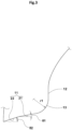
FIG 3 is an enlarged view showing the outline of the bead portion ofFIG 2 . - An embodiment of the present invention will now be described in detail in conjunction with accompanying drawings.
-
FIG 1 is a tire meridian cross-sectional view including the tire rotation axis of a motorcycle tire 1 according to the present embodiment under a regular rim assembled state. The motorcycle tire 1 in the present embodiment is for a rear wheel of a motorcycle suitable for on-road sports running. However, the present invention is not limited to such application. - The regular rim assembled state is such that the tire is mounted on a regular rim R and inflated to a normal pressure.
- The regular rim is a wheel rim specified for the tire by a standard included in a standardization system on which the tire is based, for example, the "normal wheel rim" in JATMA, "Design Rim" in TRA, and "Measuring Rim" in ETRTO.
- The normal pressure is air pressure specified for the tire by a standard included in a standardization system on which the tire is based, for example, the "maximum air pressure" in JATMA, maximum value listed in the "TIRE LOAD LIMITS AT VARIOUS COLD INFLATION PRESSURES" table in TRA, and "INFLATION PRESSURE" in ETRTO.
- As shown in
FIG 1 , the tire 1 of the present embodiment comprises atread portion 2 having tread edge Te, a pair of axially spacedbead portions 4 each with anannular bead core 5 embedded therein, a pair ofsidewall portions 3 extending between the tread edge Te and beadportions 4, and a carcass 6 extending between thebead portions 4 through thetread portion 2 and thesidewall portions 3. - As a characteristic of a motorcycle tire, the
tread portion 2 is curved in an arc-shape convex toward the radially outside so that thetread surface 2s can secure a sufficient contact area during turning or cornering with a large camber angle. - As the
tread portion 2 is curved, thetread 2s thereof is also curved, and the tread edges Te thereof contact with the road surface when turning at the maximum camber angle. - The carcass 6 is composed of at least one
carcass ply 6A of rubberized carcass cords. In the present embodiment, the carcass 6 is composed of asingle carcass ply 6A, but may be composed of a plurality ofcarcass plies 6A. - The
carcass ply 6A extends between thebead portions 4 through thetread portion 2 and thesidewall portions 3, and is turned up around thebead core 5 in each of thebead portions 4 from the axially inside to the axially outside so as to form a pair of turned-up portions 6b and a main portion 6a therebetween. - In order to reinforce the
tread portion 2, thetread portion 2 is provided with a belt 7 and a band 8, for example. - The belt 7 is composed of at least one belt ply of parallel belt cords inclined at 10 to 45 degrees with respect to the tire circumferential direction, for example.
- In the present embodiment, the belt 7 is composed of only one belt ply, but may be composed of a plurality of belt plies.
- The band 8 comprises a jointless band ply made of at least one band cord spirally wound at an angle of not more than 5 degrees with respect to the tire circumferential direction, for example.
-
FIG 2 shows one of thebead portions 4. As shown, each of thebead portions 4 has an axiallyouter surface 12 on the axially outer side of thebead core 5, abead bottom surface 11 on the radially inner side of thebead core 5, and abead heel surface 13 extending in an arc shape and connecting between the axiallyouter surface 12 and thebead bottom surface 11. - When the tire 1 is mounted on the regular rim R, the axially
outer surface 12, thebead heel surface 13 and thebead bottom surface 11 contact with the inner surface of the regular rim R from the rim flange inner surface to the bead seat of the rim. - According to the present invention, when the
bead portions 4 are held so that the axial distance L1 between the axiallyouter surfaces 12 of thebead portions 4 becomes equal to the rim width W1 (shown inFIG 1 ) of the regular rim, without the tire being mounted thereon, the following conditional expression (1):
- "Dc" is the inner diameter of the
annular bead core 5 measured at an axial position corresponding to the center in the tire axial direction of thebead core 5, - "T" is the distance in the tire radial direction between the radially
inner surface 5a of thebead core 5 and thebead bottom surface 11 measured at the above-mentioned axial position corresponding to the center in the tire axial direction of thebead core 5, - "Dr" is the rim diameter of the regular rim R.
- The rim diameter corresponds to the diameter measured at the bead baseline BL which is the rim diameter position defined by the standard.
- The rim width W1 of the regular rim is also defined by the standard.
- The axial distance L1 is measured at a radial position corresponding to the centers in the tire radial direction of the
bead cores 5. - In this specification, unless otherwise noted, dimensions and the like of various tire portions refer to values measured under the non-rim assembled state.
- If the inner diameter Dc of the
bead core 5 slightly varies depending on the measurement position in the tire circumferential direction, it is desirable to use the average value of the values measured at a plurality of different positions in the tire circumferential direction, as the inner diameter Dc. The average value is obtained from at least two inner diameter values measured at positions, for example, shifted by 90 degrees in the tire circumferential direction. It is desirable that the average value is determined based on inner diameters measured at as many positions as possible. - As for the distance T, as well, it is desirable to adopt the average value obtained in the same manner as in the inner diameter Dc.
- By adopting the configuration as described above, the tire 1 according to the present invention can be improved in robustness in terms of fitability with a wheel rim and maneuvering stability as follows.
- The "Dr+2T" in the above conditional expression (1) corresponds to the outer diameter of the substantial part that the bead core tightens. That is, in the present invention, the inner diameter Dc of the
bead core 5, and the outer diameter of the substantial part that the bead core tightens are defined with high accuracy by the conditional expression (1). As a result, even if the rim diameter of the rim on which the tire 1 is mounted is smaller or larger than the design value, or even if the rim diameter varies greatly depending on the measurement position, the fitability with the wheel rim and the maneuvering stability are less likely to be excessively lowered. Therefore, the tire 1 according to the present invention can improve robustness in terms of fitability with the wheel rim and maneuvering stability. - In this specification, fitability with a wheel rim means workability when mounting a tire on a wheel rim. When mounting a tire on a rim, the bead portion needs to climb over the hump of the bead seat of the rim, by injecting a high-pressure air in the tire. Thus, the lower the injected air pressure, the better the fitability with the wheel rim. On the other hand, maneuvering stability means stability when a two-wheeled vehicle equipped with a tire is run, and there is a tendency that the greater the fitting force of the tire acting on the rim, the higher the maneuvering stability.
- Thus, the fitability with the wheel rim and the maneuvering stability tend to contradict each other.
- In the tire 1 according to the present invention, due to the configuration described above, it can be expected to improve both the fitability with the wheel rim and the maneuvering stability which tend to conflict.
- In the present embodiment, the
bead core 5 has a rectangular cross-sectional shape and is surrounded by its outer surface including the radiallyinner surface 5a, a radiallyouter surface 5b, an axially outerfirst side surface 5c and an axially innersecond side surface 5d. - The corner portions where these surfaces are connected are curved in an arc shape.
- The radially
inner surface 5a andouter surface 5b each extend along the tire axial direction. Thefirst side surface 5c andsecond side surface 5d each extend along the tire radial direction, and the angle difference between thefirst side surface 5c andsecond side surface 5d is, for example, not more than 10 degrees, preferably not more than 5 degrees. - In the present embodiment, the
first side surface 5c andsecond side surface 5d are substantially parallel with each other. -
Such bead core 5 reliably prevents thebead portion 4 from collapsing, and serves to enhance maneuvering stability. - In the above-described non-rim assembled state, the diameter Dv of the intersection of a virtual first
straight line 16 extending axially outwardly from thebead bottom surface 11 and a virtual secondstraight line 17 extending radially inwardly from the axiallyouter surface 12 is preferably 99.2% to 99.6%, more preferably 99.3% to 99.5% of the rim diameter Dr of the regular rim. Thereby, the inner diameter of thebead portion 4 is optimized, and it is possible to improve the resistance to bead unseating and the maneuvering stability while maintaining the fitability with the wheel rim. - The first
straight line 16 corresponds to a tangent line passing through the end of thebead bottom surface 11 on thebead heel surface 13 side. - The second
straight line 17 corresponds to a tangent line passing through the end of the axiallyouter surface 12 on thebead heel surface 13 side. - The
bead heel surface 13 is curved convexly toward an oblique direction (which is toward both the axially outside and the radially inside). In the present embodiment, thebead heel surface 13 is a circular arc having a single radius of curvature. The diameter Dv corresponds to the diameter of an imaginary circle formed by connecting the points ofintersection 18 of the firststraight lines 16 and the secondstraight lines 17 over the entire circumference of the tire. - The angle θ3 between the first
straight line 16 and the secondstraight line 17 is preferably 90 to 110 degrees, more preferably 95 to 105 degrees. -
FIG 3 shows the outline of thebead portion 4. As shown, thebead bottom surface 11 is made up of afirst bottom surface 21 inclined with respect to the tire axial direction, and asecond bottom surface 22 extending from the axially inner end of thefirst bottom surface 21 at an angle with respect to the tire axial direction which is greater than thefirst bottom surface 21. Thebead bottom surface 11 including thefirst bottom surface 21 and thesecond bottom surface 22 improves the fitability with the heel rim and the resistance to bead unseating in a well-balanced manner. - In the cross section of the tire in the non-rim assembled state, the
first bottom surface 21 extends linearly, and the angle θ1 of thefirst bottom surface 21 with respect to the tire axial direction is not more than 15 degrees, preferably not more than 10 degrees, more preferably not more than 7 degrees. For example, the angle θ1 is 3 to 7 degrees. The angle between thefirst bottom surface 21 and the radiallyinner surface 5a of thebead core 5 is preferably in a range from 0 to 10 degrees. - In the present embodiment, the angle of the
first bottom surface 21 is the same as the angle of the firststraight line 16 with respect to the tire axial direction. - In the cross section of the tire in the non-rim assembled state, the
second bottom surface 22 extends linearly, and the angle θ2 of thesecond bottom surface 22 with respect to the tire axial direction is not more than 30 degrees, preferably not more than 24 degrees. For example, the angle θ2 is 18 to 24 degrees. Such secondbottom surface 22 can improve the resistance to bead unseating while maintaining the fitability with the wheel rim. - In order to improve the fitability with the wheel rim and the resistance to bead unseating in a well-balanced manner, as shown in
FIG 2 , the angle θ4 between thefirst bottom surface 21 and thesecond bottom surface 22 is preferably 150 degrees or more, more preferably 160 degrees or less, but preferably 175 degrees or less, more preferably 170 degrees or less. - The angle θ4 between the
first bottom surface 21 and thesecond bottom surface 22 is larger than the angle θ3 between the firststraight line 16 and the secondstraight line 17. The difference between the angle θ3 and the angle θ4 is, for example, 60 to 80 degrees, preferably 65 to 75 degrees. Thereby, the pressure of the axiallyouter surface 12 acting on the wheel rim, and the pressure of thesecond bottom surface 22 acting on the wheel rim are improved in a well-balanced manner, and excellent maneuvering stability is exhibited. - The
boundary 25 between thefirst bottom surface 21 and thesecond bottom surface 22 is positioned in a region obtained by virtually radially inwardly extending the axially extending range of thebead core 5 in the cross section of the tire. - Preferably, the
boundary 25 is positioned axially inward of the center in the tire axial direction of thebead core 5. - The axial distance between the
boundary 25 and the center of thebead core 5 is, for example, 25% to 35% of the axial width of thebead core 5. - Thereby, the
second bottom surface 22 can be in close contact with the wheel rim, and the durability of thebead portion 4 is improved. - The distance T is set in a range from 20% to 40%, preferably 25% to 35% of the width in the tire radial direction of the
bead core 5. Thereby, the fitability with the wheel rim and the maneuvering stability are improved in a well-balanced manner. - The axially
outer surface 12 comprises a portion extending linearly from the end on the bead heel side of the axiallyouter surface 12 in the cross section of the tire. - This portion has an angular difference of not more than 5 degrees from the
first side surface 5c of thebead core 5. - At the position in the tire radial direction of the center in the tire radial direction of the
bead core 5, the thickness of the rubber on the axially outer side of thebead core 5 is preferably not more than 3.0 mm. This makes it easier for thebead portion 4 to climb over the hump when mounting the tire on the wheel rim, and the fitability with the wheel rim is improved. - As shown in
FIG 3 , in the cross section of thebead portion 4, the radius r1 of curvature of thebead heel surface 13 is preferably set in a range from 2.5 to 4.0 mm. Thereby, the fitability with the heel rim and the resistance to bead unseating can be enhanced in a well-balanced manner. - While detailed description has been made of the motorcycle tire as an embodiment of the present invention, the present invention can be embodied in various forms as claimed.
- Based on the structure shown in
FIG 1 , motorcycle tires (for rear wheel) of size 190/55ZR17 were experimentally manufactured as test tires (comparative examples Ref.1-Ref.2 and working examples EC.1-EX.10), changing the value of Dc/(Dr+2T). Specifications of the test tires are shown in Table 1. - The test tires were tested for fitability with the wheel rim, maneuvering stability, resistance to bead unseating, and robustness in terms of the fitability with the wheel rim and the maneuvering stability.
- Common specifications and test methods for the test tires are as follows.
- Rim size: MT6.00
- Tire inflation pressure: 250 kPa
- Test vehicle: 1000cc motorcycle
- When mounting the test tire on the wheel rim by injecting high-pressure air into the inside of the tire, the air pressure required for the bead portion to climb over the hump of the heel rim was measured.
- As the test results, reciprocals of the measured pressure values are indicated in Table 1 by an index based on Comparative example Ref. 1 being 100, wherein the larger the value, the better the fitability with the wheel rim.
- According to Japanese Industrial Standard (JIS) D4230, a bead unseating test was conducted. In the test, a lateral force was applied to the bead portion of the test tire mounted on the wheel rim and substantially un-inflated, and the resistance force was measured when the bead portion came off the rim.
- The results are indicated in Table 1 by an index based on Comparative Example Ref. 1 being 100, wherein the larger the value, the better the resistance to bead unseating.
- When the test vehicle with the test tire was run on a circuit, the test rider evaluated the maneuvering stability.
- The results are indicated in Table 1 by an index based on Comparative example Ref. 1 being 100, wherein the larger the number, the better the maneuvering stability.
- Using a tire bead compression machine manufactured by Hoffmann, the fitting force of the bead portion to the wheel rim (so called "Hoffman fitting force" in kN) was measured. Based on the measured values, the robustness in terms of the fitability with the wheel rim and maneuvering stability, were evaluated.
- A specific evaluation method is as follows.
(1) The test tire was mounted on a test jig capable of adjusting to an arbitrary rim diameter. Then, there were measured the fitting force when the rim diameter of the jig is 0.3 mm larger than the rim diameter of the regular rim (this measured value is hereinafter referred to as the first measured value), and the fitting force when the rim diameter of the jig is 0.3 mm smaller than the rim diameter of the regular rim was measured (this measured value is hereinafter referred to as the second measured value).
(2) The first measured value and the second measured value were plotted on a graph where the horizontal axis is the rim diameter, and the vertical axis is the fitting force. Then, a straight line was drawn between the two plotted points, and the gradient of the straight line was measured.
(3) The robustness was evaluated by the gradient of the straight line measured in (2) above. As the test results, reciprocals of the measured gradient of the straight lines are indicated in Table 1 by an index based on Comparative example Ref.1 being 100, wherein the larger the value, the smaller the change in the fitting force due to the difference in rim diameter, which indicates that the robustness is excellent.Table 1 Tire Ref.1 Ref.2 Ex.1 Ex.2 Ex.3 Ex.4 Ex.5 Ex.6 Ex.7 Ex.8 Ex.9 Ex.10 Dc/(Dr+2T) 0.98 1.1 0.99 1 0.99 0.99 0.99 0.99 0.99 0.99 0.99 0.99 Dv/Dr(%) 99.3 99.3 99.3 99.3 99.5 99.3 99.3 99.3 99.3 99.3 99.3 99.3 bead heel surface curvature radius r1 (mm) 2.5 2.5 2.5 2.5 2.5 1.5 3.5 4.5 2.5 2.5 2.5 2.5 first bottom surface angle θ1 (deg.) 5 5 5 5 5 5 5 5 7 9 5 5 second bottom surface angle θ2 (deg.) 21 21 21 21 21 21 21 21 21 21 23 25 fitability with rim 100 120 110 110 115 100 115 120 110 95 110 100 bead unseating 100 85 95 95 95 95 95 90 110 110 100 100 maneuvering stability 100 90 110 100 90 95 105 105 110 105 105 105 robustness 100 100 115 120 105 115 115 105 115 115 120 120 - From the test results, it was confirmed that the example tires according to the present invention had improved robustness in terms of fitting to the rim and maneuvering stability. In addition, it was confirmed that the example tires had well-balanced improvement in fitability with the wheel rim, resistance to bead unseating, and maneuvering stability.
-
- 4
- bead portion
- 5
- bead core
- 11
- bead bottom surface
- R
- regular rim
- Dc
- inner diameter of bead core at axial center position of bead core
- Dr
- rim diameter of regular rim
- T
- radial distance from bead core inner surface to bead bottom surface at axial center position of bead core
Claims (6)
- A motorcycle (1) tire comprising a pair of bead portions (4) each with an annular bead core (5) embedded therein and each having a bead bottom surface (11) located radially inside the bead core (5),
characterized in that
in a non-rim assembled state of the tire (1) in which the bead portions (4) are held such that the axial distance (L1) between the axially outer surfaces (12) of the bead portions (4) matches a rim width (W1) of a regular rim (R) for the tire (1), the following conditional expression (1): "Dc" is the inner diameter of the annular bead core (5) measured at an axial position corresponding to the center in the tire axial direction of the bead core (5),"Dr" is the diameter of the regular rim (R), and"T" is the radial distance from the radially inner surface (5a) of the bead core (5) to the bead bottom surface (11) measured at the axial position corresponding to the center in the tire axial direction of the bead core (5).
 - The motorcycle tire according to claim 1, wherein
in the non-rim assembled state, the diameter Dv of the intersection (18) of a virtual first straight line (16) extending axially outwardly from the bead bottom surface (11) and a virtual second straight line (17) extending radially inwardly from the axially outer surface (12) is 99.2% to 99.6% of the rim diameter Dr of the regular rim (R). - The motorcycle tire according to claim 1 or 2, whereineach of the bead portions (4) has an axially outer surface (12) on the axially outer side of the bead core (5), and a bead heel surface (13) extending in an arc shape and connecting between the axially outer surface (12) and the bead bottom surface (11), andin the cross section of the bead portion (4), the radius (r1) of curvature of the bead heel surface (13) is in a range from 2.5 to 4.0 mm.
- The motorcycle tire according to any one of claims 1 to 3, wherein
the bead bottom surface (11) comprises a first bottom surface (21), and a second bottom surface (22) extending axially inwardly from the first bottom surface (21) at an angle greater than that of the first bottom surface (21) with respect to the tire axial direction. - The motorcycle tire according to claim 4, wherein
the first bottom surface (21) has an angle (θ1) of not more than 7 degrees with respect to the tire axial direction. - The motorcycle tire according to claim 4 or 5, wherein
the second bottom surface (22) has an angle (θ2) of not more than 24 degrees with respect to the tire axial direction.
Applications Claiming Priority (1)
| Application Number | Priority Date | Filing Date | Title |
|---|---|---|---|
| JP2022052296A JP7838361B2 (en) | 2022-03-28 | 2022-03-28 | Motorcycle tires |
Publications (2)
| Publication Number | Publication Date |
|---|---|
| EP4253096A1 EP4253096A1 (en) | 2023-10-04 |
| EP4253096B1 true EP4253096B1 (en) | 2025-07-09 |
Family
ID=85703819
Family Applications (1)
| Application Number | Title | Priority Date | Filing Date |
|---|---|---|---|
| EP23162031.1A Active EP4253096B1 (en) | 2022-03-28 | 2023-03-15 | Motorcycle tire |
Country Status (4)
| Country | Link |
|---|---|
| US (1) | US20230322030A1 (en) |
| EP (1) | EP4253096B1 (en) |
| JP (1) | JP7838361B2 (en) |
| CN (1) | CN116811487A (en) |
Family Cites Families (13)
| Publication number | Priority date | Publication date | Assignee | Title |
|---|---|---|---|---|
| JP2000198327A (en) * | 1998-12-28 | 2000-07-18 | Sumitomo Rubber Ind Ltd | Tubeless tires |
| JP4926314B2 (en) * | 2000-02-15 | 2012-05-09 | 横浜ゴム株式会社 | Pneumatic tire |
| JP4463603B2 (en) * | 2004-03-29 | 2010-05-19 | 住友ゴム工業株式会社 | Motorcycle tires |
| JP2006327440A (en) * | 2005-05-27 | 2006-12-07 | Yokohama Rubber Co Ltd:The | Radial tire for aircraft |
| FR2957020B1 (en) * | 2010-03-05 | 2012-03-16 | Michelin Soc Tech | TIRE FOR VEHICLES COMPRISING A TREAD TAPE CONSISTING OF MULTIPLE MIXTURES AND A RADIAL CARCASS FRAME FORMED OF AT LEAST TWO LAYERS. |
| JP2013063676A (en) * | 2011-09-15 | 2013-04-11 | Sumitomo Rubber Ind Ltd | Pneumatic tire |
| JP5722935B2 (en) * | 2013-02-15 | 2015-05-27 | 株式会社ブリヂストン | Pneumatic tire |
| JP6002089B2 (en) * | 2013-06-06 | 2016-10-05 | 住友ゴム工業株式会社 | Heavy duty tire |
| JP6760003B2 (en) * | 2016-11-16 | 2020-09-23 | 住友ゴム工業株式会社 | Pneumatic tires |
| JP6662367B2 (en) * | 2017-12-01 | 2020-03-11 | 横浜ゴム株式会社 | Pneumatic tire |
| JP6834922B2 (en) * | 2017-12-01 | 2021-02-24 | 横浜ゴム株式会社 | Pneumatic tires |
| JP7087426B2 (en) * | 2018-02-08 | 2022-06-21 | 横浜ゴム株式会社 | Pneumatic tires |
| JP7367488B2 (en) * | 2019-11-26 | 2023-10-24 | 住友ゴム工業株式会社 | pneumatic tires |
-
2022
- 2022-03-28 JP JP2022052296A patent/JP7838361B2/en active Active
-
2023
- 2023-03-09 US US18/119,467 patent/US20230322030A1/en not_active Abandoned
- 2023-03-13 CN CN202310244254.7A patent/CN116811487A/en active Pending
- 2023-03-15 EP EP23162031.1A patent/EP4253096B1/en active Active
Also Published As
| Publication number | Publication date |
|---|---|
| US20230322030A1 (en) | 2023-10-12 |
| JP7838361B2 (en) | 2026-04-01 |
| EP4253096A1 (en) | 2023-10-04 |
| JP2023145032A (en) | 2023-10-11 |
| CN116811487A (en) | 2023-09-29 |
Similar Documents
| Publication | Publication Date | Title |
|---|---|---|
| EP2724871B1 (en) | Passenger vehicle | |
| EP3556573B1 (en) | Tire | |
| EP0872361B1 (en) | Vehicle tyre | |
| EP2735455B1 (en) | Run-flat tire and mounting method thereof | |
| EP3730314B1 (en) | Tire for motorcycles and tire set for motorcycles | |
| US11207927B2 (en) | Pneumatic tire | |
| EP3798026B1 (en) | Tyre and rim assembly | |
| EP3878667B1 (en) | Pneumatic tire | |
| EP4253096B1 (en) | Motorcycle tire | |
| EP4253087B1 (en) | Motorcycle tyre | |
| EP4282666B1 (en) | Tire | |
| EP3736142B1 (en) | Motorcycle tire | |
| EP3659822B1 (en) | Tire | |
| EP4039507B1 (en) | Motorcycle tyre | |
| EP3838630A1 (en) | Pneumatic tire | |
| EP3326842B1 (en) | Motorcycle tire | |
| EP4321351B1 (en) | Tire | |
| EP4234271B1 (en) | Motorcycle tyre set | |
| EP4005823B1 (en) | Bias tyre for two-wheel vehicle | |
| EP4223558B1 (en) | Motorcycle tire pair | |
| EP4098459B1 (en) | Heavy-duty tire | |
| EP3900954B1 (en) | Pneumatic tyre | |
| EP3539797A1 (en) | Tire |
Legal Events
| Date | Code | Title | Description |
|---|---|---|---|
| PUAI | Public reference made under article 153(3) epc to a published international application that has entered the european phase |
Free format text: ORIGINAL CODE: 0009012 |
|
| STAA | Information on the status of an ep patent application or granted ep patent |
Free format text: STATUS: THE APPLICATION HAS BEEN PUBLISHED |
|
| AK | Designated contracting states |
Kind code of ref document: A1 Designated state(s): AL AT BE BG CH CY CZ DE DK EE ES FI FR GB GR HR HU IE IS IT LI LT LU LV MC ME MK MT NL NO PL PT RO RS SE SI SK SM TR |
|
| STAA | Information on the status of an ep patent application or granted ep patent |
Free format text: STATUS: REQUEST FOR EXAMINATION WAS MADE |
|
| 17P | Request for examination filed |
Effective date: 20240209 |
|
| RBV | Designated contracting states (corrected) |
Designated state(s): AL AT BE BG CH CY CZ DE DK EE ES FI FR GB GR HR HU IE IS IT LI LT LU LV MC ME MK MT NL NO PL PT RO RS SE SI SK SM TR |
|
| P01 | Opt-out of the competence of the unified patent court (upc) registered |
Effective date: 20240327 |
|
| GRAP | Despatch of communication of intention to grant a patent |
Free format text: ORIGINAL CODE: EPIDOSNIGR1 |
|
| STAA | Information on the status of an ep patent application or granted ep patent |
Free format text: STATUS: GRANT OF PATENT IS INTENDED |
|
| INTG | Intention to grant announced |
Effective date: 20250320 |
|
| GRAS | Grant fee paid |
Free format text: ORIGINAL CODE: EPIDOSNIGR3 |
|
| GRAA | (expected) grant |
Free format text: ORIGINAL CODE: 0009210 |
|
| STAA | Information on the status of an ep patent application or granted ep patent |
Free format text: STATUS: THE PATENT HAS BEEN GRANTED |
|
| AK | Designated contracting states |
Kind code of ref document: B1 Designated state(s): AL AT BE BG CH CY CZ DE DK EE ES FI FR GB GR HR HU IE IS IT LI LT LU LV MC ME MK MT NL NO PL PT RO RS SE SI SK SM TR |
|
| REG | Reference to a national code |
Ref country code: GB Ref legal event code: FG4D |
|
| REG | Reference to a national code |
Ref country code: CH Ref legal event code: EP |
|
| REG | Reference to a national code |
Ref country code: IE Ref legal event code: FG4D |
|
| REG | Reference to a national code |
Ref country code: DE Ref legal event code: R096 Ref document number: 602023004605 Country of ref document: DE |
|
| REG | Reference to a national code |
Ref country code: NL Ref legal event code: MP Effective date: 20250709 |
|
| PG25 | Lapsed in a contracting state [announced via postgrant information from national office to epo] |
Ref country code: PT Free format text: LAPSE BECAUSE OF FAILURE TO SUBMIT A TRANSLATION OF THE DESCRIPTION OR TO PAY THE FEE WITHIN THE PRESCRIBED TIME-LIMIT Effective date: 20251110 |
|
| PG25 | Lapsed in a contracting state [announced via postgrant information from national office to epo] |
Ref country code: NL Free format text: LAPSE BECAUSE OF FAILURE TO SUBMIT A TRANSLATION OF THE DESCRIPTION OR TO PAY THE FEE WITHIN THE PRESCRIBED TIME-LIMIT Effective date: 20250709 |
|
| REG | Reference to a national code |
Ref country code: AT Ref legal event code: MK05 Ref document number: 1811541 Country of ref document: AT Kind code of ref document: T Effective date: 20250709 |
|
| PG25 | Lapsed in a contracting state [announced via postgrant information from national office to epo] |
Ref country code: IS Free format text: LAPSE BECAUSE OF FAILURE TO SUBMIT A TRANSLATION OF THE DESCRIPTION OR TO PAY THE FEE WITHIN THE PRESCRIBED TIME-LIMIT Effective date: 20251109 |
|
| PG25 | Lapsed in a contracting state [announced via postgrant information from national office to epo] |
Ref country code: NO Free format text: LAPSE BECAUSE OF FAILURE TO SUBMIT A TRANSLATION OF THE DESCRIPTION OR TO PAY THE FEE WITHIN THE PRESCRIBED TIME-LIMIT Effective date: 20251009 |
|
| REG | Reference to a national code |
Ref country code: LT Ref legal event code: MG9D |
|
| PG25 | Lapsed in a contracting state [announced via postgrant information from national office to epo] |
Ref country code: AT Free format text: LAPSE BECAUSE OF FAILURE TO SUBMIT A TRANSLATION OF THE DESCRIPTION OR TO PAY THE FEE WITHIN THE PRESCRIBED TIME-LIMIT Effective date: 20250709 |
|
| PG25 | Lapsed in a contracting state [announced via postgrant information from national office to epo] |
Ref country code: FI Free format text: LAPSE BECAUSE OF FAILURE TO SUBMIT A TRANSLATION OF THE DESCRIPTION OR TO PAY THE FEE WITHIN THE PRESCRIBED TIME-LIMIT Effective date: 20250709 |
|
| PG25 | Lapsed in a contracting state [announced via postgrant information from national office to epo] |
Ref country code: HR Free format text: LAPSE BECAUSE OF FAILURE TO SUBMIT A TRANSLATION OF THE DESCRIPTION OR TO PAY THE FEE WITHIN THE PRESCRIBED TIME-LIMIT Effective date: 20250709 |
|
| PG25 | Lapsed in a contracting state [announced via postgrant information from national office to epo] |
Ref country code: GR Free format text: LAPSE BECAUSE OF FAILURE TO SUBMIT A TRANSLATION OF THE DESCRIPTION OR TO PAY THE FEE WITHIN THE PRESCRIBED TIME-LIMIT Effective date: 20251010 |
|
| PG25 | Lapsed in a contracting state [announced via postgrant information from national office to epo] |
Ref country code: SE Free format text: LAPSE BECAUSE OF FAILURE TO SUBMIT A TRANSLATION OF THE DESCRIPTION OR TO PAY THE FEE WITHIN THE PRESCRIBED TIME-LIMIT Effective date: 20250709 |
|
| PG25 | Lapsed in a contracting state [announced via postgrant information from national office to epo] |
Ref country code: LV Free format text: LAPSE BECAUSE OF FAILURE TO SUBMIT A TRANSLATION OF THE DESCRIPTION OR TO PAY THE FEE WITHIN THE PRESCRIBED TIME-LIMIT Effective date: 20250709 |
|
| PG25 | Lapsed in a contracting state [announced via postgrant information from national office to epo] |
Ref country code: PL Free format text: LAPSE BECAUSE OF FAILURE TO SUBMIT A TRANSLATION OF THE DESCRIPTION OR TO PAY THE FEE WITHIN THE PRESCRIBED TIME-LIMIT Effective date: 20250709 Ref country code: BG Free format text: LAPSE BECAUSE OF FAILURE TO SUBMIT A TRANSLATION OF THE DESCRIPTION OR TO PAY THE FEE WITHIN THE PRESCRIBED TIME-LIMIT Effective date: 20250709 |
|
| PG25 | Lapsed in a contracting state [announced via postgrant information from national office to epo] |
Ref country code: RS Free format text: LAPSE BECAUSE OF FAILURE TO SUBMIT A TRANSLATION OF THE DESCRIPTION OR TO PAY THE FEE WITHIN THE PRESCRIBED TIME-LIMIT Effective date: 20251009 |
|
| PG25 | Lapsed in a contracting state [announced via postgrant information from national office to epo] |
Ref country code: ES Free format text: LAPSE BECAUSE OF FAILURE TO SUBMIT A TRANSLATION OF THE DESCRIPTION OR TO PAY THE FEE WITHIN THE PRESCRIBED TIME-LIMIT Effective date: 20250709 |
|
| PG25 | Lapsed in a contracting state [announced via postgrant information from national office to epo] |
Ref country code: SM Free format text: LAPSE BECAUSE OF FAILURE TO SUBMIT A TRANSLATION OF THE DESCRIPTION OR TO PAY THE FEE WITHIN THE PRESCRIBED TIME-LIMIT Effective date: 20250709 |
|
| PG25 | Lapsed in a contracting state [announced via postgrant information from national office to epo] |
Ref country code: DK Free format text: LAPSE BECAUSE OF FAILURE TO SUBMIT A TRANSLATION OF THE DESCRIPTION OR TO PAY THE FEE WITHIN THE PRESCRIBED TIME-LIMIT Effective date: 20250709 |
|
| PGFP | Annual fee paid to national office [announced via postgrant information from national office to epo] |
Ref country code: DE Payment date: 20260128 Year of fee payment: 4 |
|
| PG25 | Lapsed in a contracting state [announced via postgrant information from national office to epo] |
Ref country code: IT Free format text: LAPSE BECAUSE OF FAILURE TO SUBMIT A TRANSLATION OF THE DESCRIPTION OR TO PAY THE FEE WITHIN THE PRESCRIBED TIME-LIMIT Effective date: 20250709 |
|
| PGFP | Annual fee paid to national office [announced via postgrant information from national office to epo] |
Ref country code: FR Payment date: 20260209 Year of fee payment: 4 |
|
| PG25 | Lapsed in a contracting state [announced via postgrant information from national office to epo] |
Ref country code: CZ Free format text: LAPSE BECAUSE OF FAILURE TO SUBMIT A TRANSLATION OF THE DESCRIPTION OR TO PAY THE FEE WITHIN THE PRESCRIBED TIME-LIMIT Effective date: 20250709 |
|
| PG25 | Lapsed in a contracting state [announced via postgrant information from national office to epo] |
Ref country code: SK Free format text: LAPSE BECAUSE OF FAILURE TO SUBMIT A TRANSLATION OF THE DESCRIPTION OR TO PAY THE FEE WITHIN THE PRESCRIBED TIME-LIMIT Effective date: 20250709 Ref country code: EE Free format text: LAPSE BECAUSE OF FAILURE TO SUBMIT A TRANSLATION OF THE DESCRIPTION OR TO PAY THE FEE WITHIN THE PRESCRIBED TIME-LIMIT Effective date: 20250709 |