EP3838630A1 - Pneumatic tire - Google Patents
Pneumatic tire Download PDFInfo
- Publication number
- EP3838630A1 EP3838630A1 EP20208916.5A EP20208916A EP3838630A1 EP 3838630 A1 EP3838630 A1 EP 3838630A1 EP 20208916 A EP20208916 A EP 20208916A EP 3838630 A1 EP3838630 A1 EP 3838630A1
- Authority
- EP
- European Patent Office
- Prior art keywords
- tire
- portions
- radial direction
- raised
- pair
- Prior art date
- Legal status (The legal status is an assumption and is not a legal conclusion. Google has not performed a legal analysis and makes no representation as to the accuracy of the status listed.)
- Granted
Links
- 239000011324 bead Substances 0.000 claims abstract description 36
- 238000005096 rolling process Methods 0.000 description 14
- 238000012360 testing method Methods 0.000 description 7
- 239000004677 Nylon Substances 0.000 description 1
- 229920000297 Rayon Polymers 0.000 description 1
- 230000000694 effects Effects 0.000 description 1
- 239000000835 fiber Substances 0.000 description 1
- 229920001778 nylon Polymers 0.000 description 1
- 229920000728 polyester Polymers 0.000 description 1
- 239000002964 rayon Substances 0.000 description 1
- 238000010998 test method Methods 0.000 description 1
Images


Classifications
-
- B—PERFORMING OPERATIONS; TRANSPORTING
- B60—VEHICLES IN GENERAL
- B60C—VEHICLE TYRES; TYRE INFLATION; TYRE CHANGING; CONNECTING VALVES TO INFLATABLE ELASTIC BODIES IN GENERAL; DEVICES OR ARRANGEMENTS RELATED TO TYRES
- B60C13/00—Tyre sidewalls; Protecting, decorating, marking, or the like, thereof
- B60C13/002—Protection against exterior elements
-
- B—PERFORMING OPERATIONS; TRANSPORTING
- B60—VEHICLES IN GENERAL
- B60C—VEHICLE TYRES; TYRE INFLATION; TYRE CHANGING; CONNECTING VALVES TO INFLATABLE ELASTIC BODIES IN GENERAL; DEVICES OR ARRANGEMENTS RELATED TO TYRES
- B60C13/00—Tyre sidewalls; Protecting, decorating, marking, or the like, thereof
- B60C13/02—Arrangement of grooves or ribs
-
- B—PERFORMING OPERATIONS; TRANSPORTING
- B60—VEHICLES IN GENERAL
- B60C—VEHICLE TYRES; TYRE INFLATION; TYRE CHANGING; CONNECTING VALVES TO INFLATABLE ELASTIC BODIES IN GENERAL; DEVICES OR ARRANGEMENTS RELATED TO TYRES
- B60C15/00—Tyre beads, e.g. ply turn-up or overlap
- B60C15/0009—Tyre beads, e.g. ply turn-up or overlap features of the carcass terminal portion
- B60C15/0036—Tyre beads, e.g. ply turn-up or overlap features of the carcass terminal portion with high ply turn-up, i.e. folded around the bead core and terminating radially above the point of maximum section width
-
- B—PERFORMING OPERATIONS; TRANSPORTING
- B60—VEHICLES IN GENERAL
- B60C—VEHICLE TYRES; TYRE INFLATION; TYRE CHANGING; CONNECTING VALVES TO INFLATABLE ELASTIC BODIES IN GENERAL; DEVICES OR ARRANGEMENTS RELATED TO TYRES
- B60C9/00—Reinforcements or ply arrangement of pneumatic tyres
- B60C9/02—Carcasses
-
- B—PERFORMING OPERATIONS; TRANSPORTING
- B60—VEHICLES IN GENERAL
- B60C—VEHICLE TYRES; TYRE INFLATION; TYRE CHANGING; CONNECTING VALVES TO INFLATABLE ELASTIC BODIES IN GENERAL; DEVICES OR ARRANGEMENTS RELATED TO TYRES
- B60C13/00—Tyre sidewalls; Protecting, decorating, marking, or the like, thereof
- B60C2013/005—Physical properties of the sidewall rubber
- B60C2013/007—Thickness
-
- B—PERFORMING OPERATIONS; TRANSPORTING
- B60—VEHICLES IN GENERAL
- B60C—VEHICLE TYRES; TYRE INFLATION; TYRE CHANGING; CONNECTING VALVES TO INFLATABLE ELASTIC BODIES IN GENERAL; DEVICES OR ARRANGEMENTS RELATED TO TYRES
- B60C15/00—Tyre beads, e.g. ply turn-up or overlap
- B60C15/0009—Tyre beads, e.g. ply turn-up or overlap features of the carcass terminal portion
- B60C2015/009—Height of the carcass terminal portion defined in terms of a numerical value or ratio in proportion to section height
-
- B—PERFORMING OPERATIONS; TRANSPORTING
- B60—VEHICLES IN GENERAL
- B60C—VEHICLE TYRES; TYRE INFLATION; TYRE CHANGING; CONNECTING VALVES TO INFLATABLE ELASTIC BODIES IN GENERAL; DEVICES OR ARRANGEMENTS RELATED TO TYRES
- B60C2200/00—Tyres specially adapted for particular applications
- B60C2200/14—Tyres specially adapted for particular applications for off-road use
Definitions
- the present invention relates to a pneumatic tire.
- Patent Document 1 has proposed a pneumatic tire having a buttress portion with a raised portion.
- the raised portion is helpful for improving cut resistance performance of the buttress portion (a region on a tread portion side of each of sidewall portions extending from both ends of the tread portion in a tire radial direction).
- Patent Document 1 Japanese Unexamined Patent Application Publication No. 2019-73119
- the cut tends to occur more easily in the region on the inner side in the tire radial direction than the raised portions of the sidewall portions.
- it is also necessary to ensure basic durability for this type of pneumatic tire.
- the present invention was made in view of the above, and a primary object thereof is to provide a pneumatic tire with improved cut resistance performance in the sidewall portions.
- a distance in the tire radial direction between a bead baseline and an outer end in the tire radial direction of the respective turned up portion is 77% or less of the tire section height.
- a minimum rubber thickness between an outer surface of the carcass and an outer surface of each of the sidewall portions is 5% or less of the tire section height.
- the at least one of the pair of the sidewall portions is provided with a plurality of the raised portions arranged in the tire circumferential direction, each of the raised portions is formed so as to include a 75% position which is spaced away radially outward from a bead baseline by 75% of the tire section height, and a total of lengths in the tire circumferential direction of the raised portions is 30% or more and 80% or less of a circumferential length at the 75% position.
- At least one of the turned up portions of the carcass is arranged so as to overlap with the raised portion in the tire radial direction. Thereby, the cut resistance performance of the at least one of the sidewall portions is improved.
- the length in the tire radial direction of the overlapping portion of the turned up portion and the raised portion is 5% or more and 40% or less of the tire section height.
- the “standard state” is a state in which the tire is mounted on a standard rim (not shown), inflated to a standard inner pressure, and loaded with no tire load.
- a standard rim not shown
- the dimensions and the like of various parts of the tire are values measured in the standard state.
- the "standard rim” is a wheel rim specified for the concerned tire by a standard included in a standardization system on which the tire is based, for example, the "normal wheel rim” in JATMA, "Design Rim” in TRA, and “Measuring Rim” in ETRTO.
- the "standard inner pressure” is air pressure specified for the concerned tire by a standard included in a standardization system on which the tire is based, for example, the maximum air pressure in JATMA, maximum value listed in the "TIRE LOAD LIMITS AT VARIOUS COLD INFLATION PRESSURES" table in TRA, and "INFLATION PRESSURE” in ETRTO.
- the tire 1 of the present embodiment is provided with a tread portion 2, a pair of sidewall portions 3, a pair of bead portions 4 each having a bead core 5 embedded therein, and a carcass 6 extending between the bead portions 4 in a toroidal manner.
- a buttress portion 8 of at least one of the pair of the sidewall portions 3 is formed with at least one raised portion 10 protruding outward in a tire axial direction.
- the raised portion 10 is provided in the buttress portions 8 of both sidewall portions 3.
- a plurality of the raised portions 10 is provided in a tire circumferential direction in each of the sidewall portions 3.
- the raised portions 10 protrude outward in the tire axial direction from a reference profile of each of the sidewall portions 3. Therefore, a design element, which is drawn by the raised portions 10, is formed on an outer surface of each of the sidewall portions 3.
- the design element can be configured in various forms such as letters, figures, symbols, geometric patterns, and the like, for example.
- the reference profile is a contour of the outer surface of each of the sidewall portions 3 when the raised portions 10 are not provided, and is convexly and smoothly curved outward in the tire axial direction.
- the raised portion 10 is helpful for improving the cut resistance performance of the sidewall portions 3. Further, in the case of a tire running on a muddy road, the raised portions 10 shear mud and dirt, therefore, the traction is improved.
- the carcass 6 is composed of two carcass plies 6A and 6B, for example.
- the carcass plies 6A and 6B include carcass cords and a topping rubber that covers the carcass cords.
- the carcass cords are arranged at an angle of 75 degrees or more and 90 degrees or less with respect to the tire circumferential direction, for example.
- organic fiber cords such as nylon, polyester, or rayon are suitably used, for example.
- the carcass 6 has a main body portion (6a) and turned up portions (6b).
- the main body portion (6a) extends between the bead cores 5 of the pair of the bead portions 4.
- Each of the turned up portions (6b) is connected with the main body portion (6a) and is turned up around the respective bead core 5 to extend outward in the tire radial direction.
- Each of the turned up portions (6b) of the present embodiment is turned up around the respective bead core 5 from the inside to the outside in the tire axial direction.
- the tread portion 2 of the present embodiment includes a belt layer 7, for example.
- the belt layer 7 includes two belt plies 7A and 7B, for example.
- Each of the belt plies 7A and 7B includes belt cords arranged obliquely with respect to the tire circumferential direction, and a topping rubber covering the belt cords, for example. It is preferred that each of the belt cords is arranged at an angle of 10 degrees or more and 45 degrees or less with respect to the tire circumferential direction.
- FIGURE 2 shows an enlarged view of one of the side wall portions 3 and one of the bead portions 4.
- the turned up portion (6b) is arranged so as to overlap with the raised portions 10 in the tire radial direction. Therefore, the cut resistance performance of the sidewall portions 3 is improved.
- a length (L1) in the tire radial direction of an overlapping portion 12 of each of the turned up portions (6b) and the respective raised portions 10 is 5% or more and 40% or less of a tire section height (h1) (shown in FIGURE 1 and the same applies hereinafter).
- the tire section height (h1) corresponds to a distance in the tire radial direction between a bead baseline (BL) in the standard state and an outer end (2t) (shown in FIGURE 1 and the same applies hereinafter) in the tire radial direction of the tread portion 2.
- BL bead baseline
- the bead baseline (BL) means a tire axial direction line that passes through a rim diameter position specified for the concerned tire by a standard on which the tire is based
- the length (L1) of the overlapping portion 12 is preferably 8% or more, more preferably 10% or more, and preferably 20% or less, more preferably 15% or less of the tire section height (h1).
- an outer end of one of the two carcass plies 6A and 6B overlaps with the raised portions 10 in the tire radial direction, and an outer end 19 of the other carcass ply does not overlap with the raised portions 10 and is arranged radially inside the raised portions 10.
- each of distances in the tire circumferential direction between the outer end 19 of the other carcass ply and inner ends 18 of the raised portions 10 is preferably smaller than a minimum thickness of the sidewall portions 3.
- the outer end 16 of the turned up portion (6b) is arranged radially inside outer ends 17 in the tire radial direction of the raised portions 10.
- the outer end 16 of the turned up portion (6b) is arranged radially inside center positions in the tire radial direction of the raised portions 10.
- a distance (L2) in the tire radial direction between the bead baseline (BL) and the outer end 16 in the tire radial direction of the turned up portion (6b) is 77% or less, and more preferably 65% or less of the tire section height (h1).
- the distance (L2) is 55% or more, preferably 60% or more of the tire section height (h1).
- Each of lengths in the tire radial direction of the raised portions 10 is 20% or more and 30% or less of the tire section height (h1), for example.
- a distance (L3) in the tire radial direction between the outer end (2t) in the tire radial direction of the tread portion 2 and the inner ends 18 in the tire radial direction of the raised portions 10 is 35% or more, and preferably 40% or more of the tire section height (h1).
- the cut resistance performance is improved in an easily damaged region of the sidewall portions 3.
- the distance (L3) is 60% or less, and more preferably 55% or less of the tire section height (h1).
- a plurality of the raised portions 10 is provided in the tire circumferential direction, and each of the raised portions 10 is formed so as to include a 75% position 20 (indicated by a two-dot chain line in FIGURE 2 and corresponding to A-A line) which is spaced radially outward away from the bead baseline (BL) by 75% of the tire section height (h1).
- FIGURE 3 shows a cross-sectional view taken along A-A line of FIGURE 2 .
- the cross-sectional view of FIGURE 3 shows a cross-section of the sidewall portion 3 taken along an imaginary plane extending along the tire circumferential direction passing through the 75% position 20.
- a total ⁇ L4 of lengths (L4) in the tire circumferential direction of the raised portions 10 is preferably 30% or more, more preferably 50% or more, and preferably 80% or less, more preferably 70% or less of a circumferential length over the entire tire circumference at the 75% position 20.
- Such arrangement of the raised portions 10 can improve the cut resistance performance while maintaining the rolling resistance low.
- each of thicknesses (t1) of the raised portions 10 from the reference profile is 2.0 mm or more and 5.0 mm or less, for example.
- a minimum rubber thickness (t2) between an outer surface of the carcass 6 and the outer surface of each of the sidewall portions 3 of the present embodiment is 5% or less of the tire section height (h1). Thereby, the rolling resistance is maintained small.
- Pneumatic tires of size 265/70R17 having the basic structure shown in FIGURE 1 were made by way of test according to the specification listed in Table 1.
- pneumatic tires were made by way of test in which the raised portions and the turned up portions did not overlap (that is, the tires did not have the overlapping portions).
- the tires in Examples and the tires in the References had substantially the same configuration except the presence or absence of the overlapping portions.
- Each of the test tires was tested for the cut resistance performance and the rolling resistance.
- the common specifications and the test methods for each of the test tires were as follows. Tire rim: 17x8.0 Tire inner pressure: 220 kPa
- the blade was pressed against the outer surface of the sidewall portion, and the energy at which the cut occurred was measured.
- the results are indicated by an index based on the energy of the Reference 1 being 100, wherein a larger numerical value shows the better cut resistance performance.
- the rolling resistance was measured while the tires were run on a drum testing machine at a constant speed with a constant longitudinal load applied to the tires.
- the results are indicated by an index based on the Reference 1 being 100, wherein a smaller numerical value shows the smaller rolling resistance.
Landscapes
- Engineering & Computer Science (AREA)
- Mechanical Engineering (AREA)
- Tires In General (AREA)
Abstract
Description
- The present invention relates to a pneumatic tire.
- The following Patent Document 1 has proposed a pneumatic tire having a buttress portion with a raised portion. The raised portion is helpful for improving cut resistance performance of the buttress portion (a region on a tread portion side of each of sidewall portions extending from both ends of the tread portion in a tire radial direction).
- [Patent Document 1]
Japanese Unexamined Patent Application Publication No.2019-73119 - In the pneumatic tire as described above, the cut tends to occur more easily in the region on the inner side in the tire radial direction than the raised portions of the sidewall portions. On the other hand, it is also necessary to ensure basic durability for this type of pneumatic tire.
- The present invention was made in view of the above, and a primary object thereof is to provide a pneumatic tire with improved cut resistance performance in the sidewall portions.
- The present invention is a pneumatic tire including a tread portion, a pair of sidewall portions, a pair of bead portions each having a bead core embedded therein, and a carcass extending between the bead portions in a toroidal manner, wherein a buttress portion of at least one of the pair of the sidewall portions is provided with at least one raised portion protruding outward in a tire axial direction, the carcass includes a main body portion and a pair of turned up portions, the main body portion extends between the bead cores of the pair of the bead portions, each of the pair of the turned up portions is turned up around the respective bead core to extend outward in a tire radial direction, in the sidewall portion which is provided with the at least one raised portion, the turned up portion is arranged so as to overlap with the raised portion in the tire radial direction, and a length in the tire radial direction of an overlapping portion of the turned up portion and the raised portion is 5% or more and 40% or less of a tire section height.
- In the present invention, it is preferred that in each of the sidewall portions, a distance in the tire radial direction between a bead baseline and an outer end in the tire radial direction of the respective turned up portion is 77% or less of the tire section height.
- In the present invention, it is preferred that a distance in the tire radial direction between an outer end in the tire radial direction of the tread portion and an inner end in the tire radial direction of the raised portion is 35% or more of the tire section height.
- In the present invention, it is preferred that a minimum rubber thickness between an outer surface of the carcass and an outer surface of each of the sidewall portions is 5% or less of the tire section height.
- In the present invention, it is preferred that the at least one raised portion protrudes outward in the tire axial direction from a reference profile of the at least one of the pair of the sidewall portions, and a thickness of the raised portion from the reference profile is 2.0 mm or more and 5.0 mm or less.
- In the present invention, it is preferred that the at least one of the pair of the sidewall portions is provided with a plurality of the raised portions arranged in the tire circumferential direction, each of the raised portions is formed so as to include a 75% position which is spaced away radially outward from a bead baseline by 75% of the tire section height, and a total of lengths in the tire circumferential direction of the raised portions is 30% or more and 80% or less of a circumferential length at the 75% position.
- In the pneumatic tire according to the present invention, at least one of the turned up portions of the carcass is arranged so as to overlap with the raised portion in the tire radial direction. Thereby, the cut resistance performance of the at least one of the sidewall portions is improved.
- In the present invention, the length in the tire radial direction of the overlapping portion of the turned up portion and the raised portion is 5% or more and 40% or less of the tire section height. Thereby, the cut resistance performance on the radially inner side of the raised portion is sufficiently improved, while end portions of the turned up portions are suppressed from being positioned excessively close to end portions in the tire axial direction of the tread portion which deform largely.
-
- [
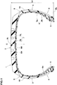
FIGURE 1 ] a lateral cross-sectional view of a tire according to an embodiment of the present invention. - [
FIGURE 2 ] an enlarged view of one of the sidewall portions and one of bead portions ofFIGURE 1 . - [
FIGURE 3 ] a cross-sectional view taken along A-A line ofFIGURE 2 . - An embodiment of the present invention will now be described in conjunction with accompanying drawings.
-
FIGURE 1 is a lateral cross-sectional view of a pneumatic tire 1 of the present embodiment in a standard state (hereinafter, may be simply referred to as "tire"). It should be noted thatFIGURE 1 is a meridian section passing through a rotational axis of the tire. As shown inFIGURE 1 , the tire 1 of the present embodiment is suitably used for SUVs designed for driving on both paved roads and rough terrain, for example. However, the present invention is not limited to such an embodiment. - The "standard state" is a state in which the tire is mounted on a standard rim (not shown), inflated to a standard inner pressure, and loaded with no tire load. Hereinafter, unless otherwise noted, the dimensions and the like of various parts of the tire are values measured in the standard state.
- The "standard rim" is a wheel rim specified for the concerned tire by a standard included in a standardization system on which the tire is based, for example, the "normal wheel rim" in JATMA, "Design Rim" in TRA, and "Measuring Rim" in ETRTO.
- The "standard inner pressure" is air pressure specified for the concerned tire by a standard included in a standardization system on which the tire is based, for example, the maximum air pressure in JATMA, maximum value listed in the "TIRE LOAD LIMITS AT VARIOUS COLD INFLATION PRESSURES" table in TRA, and "INFLATION PRESSURE" in ETRTO.
- The tire 1 of the present embodiment is provided with a
tread portion 2, a pair ofsidewall portions 3, a pair ofbead portions 4 each having abead core 5 embedded therein, and acarcass 6 extending between thebead portions 4 in a toroidal manner. - A
buttress portion 8 of at least one of the pair of thesidewall portions 3 is formed with at least one raisedportion 10 protruding outward in a tire axial direction. In the present embodiment, the raisedportion 10 is provided in thebuttress portions 8 of bothsidewall portions 3. Further, a plurality of the raisedportions 10 is provided in a tire circumferential direction in each of thesidewall portions 3. The raisedportions 10 protrude outward in the tire axial direction from a reference profile of each of thesidewall portions 3. Therefore, a design element, which is drawn by the raisedportions 10, is formed on an outer surface of each of thesidewall portions 3. The design element can be configured in various forms such as letters, figures, symbols, geometric patterns, and the like, for example. It should be noted that the reference profile is a contour of the outer surface of each of thesidewall portions 3 when the raisedportions 10 are not provided, and is convexly and smoothly curved outward in the tire axial direction. - The raised
portion 10 is helpful for improving the cut resistance performance of thesidewall portions 3. Further, in the case of a tire running on a muddy road, the raisedportions 10 shear mud and dirt, therefore, the traction is improved. - The
carcass 6 is composed of twocarcass plies carcass plies - The
carcass 6 has a main body portion (6a) and turned up portions (6b). The main body portion (6a) extends between thebead cores 5 of the pair of thebead portions 4. Each of the turned up portions (6b) is connected with the main body portion (6a) and is turned up around therespective bead core 5 to extend outward in the tire radial direction. Each of the turned up portions (6b) of the present embodiment is turned up around therespective bead core 5 from the inside to the outside in the tire axial direction. - The
tread portion 2 of the present embodiment includes abelt layer 7, for example. Thebelt layer 7 includes twobelt plies belt plies -
FIGURE 2 shows an enlarged view of one of theside wall portions 3 and one of thebead portions 4. As shown inFIGURE 2 , in thesidewall portion 3 provided with the raisedportions 10, the turned up portion (6b) is arranged so as to overlap with the raisedportions 10 in the tire radial direction. Therefore, the cut resistance performance of thesidewall portions 3 is improved. - In the present invention, a length (L1) in the tire radial direction of an overlapping
portion 12 of each of the turned up portions (6b) and the respective raisedportions 10 is 5% or more and 40% or less of a tire section height (h1) (shown inFIGURE 1 and the same applies hereinafter). Thereby, the cut resistance performance on the radially inner side of the raisedportions 10 is sufficiently improved, while end portions of the turned up portions (6b) are suppressed from being positioned excessively close to end portions in the tire axial direction of thetread portion 2 which deform largely, therefore, the durability of the tire is ensured. Further, by setting the upper limit of the length (L1) of the overlappingportion 12, it is possible that an excessive increase in the weight of thesidewall portions 3 is suppressed and eventually an increase in rolling resistance is suppressed. - It should be noted that the tire section height (h1) corresponds to a distance in the tire radial direction between a bead baseline (BL) in the standard state and an outer end (2t) (shown in
FIGURE 1 and the same applies hereinafter) in the tire radial direction of thetread portion 2. It should be noted that the bead baseline (BL) means a tire axial direction line that passes through a rim diameter position specified for the concerned tire by a standard on which the tire is based - In order to further improve the cut resistance performance while suppressing the rolling resistance, the length (L1) of the overlapping
portion 12 is preferably 8% or more, more preferably 10% or more, and preferably 20% or less, more preferably 15% or less of the tire section height (h1). - In the present embodiment, an outer end of one of the two carcass plies 6A and 6B (corresponding to an
outer end 16 of the turned up portion (6b)) overlaps with the raisedportions 10 in the tire radial direction, and anouter end 19 of the other carcass ply does not overlap with the raisedportions 10 and is arranged radially inside the raisedportions 10. In a preferred embodiment, each of distances in the tire circumferential direction between theouter end 19 of the other carcass ply and inner ends 18 of the raisedportions 10 is preferably smaller than a minimum thickness of thesidewall portions 3. Thereby, a rigidity difference is less likely to occur in the vicinity of the inner ends 18 of the raisedportions 10, therefore, local deformation of thesidewall portions 3 is suppressed. - In order to secure a distance between the
outer end 16 of the turned up portion (6b) and an end portion of thebelt layer 7, it is preferred that theouter end 16 of the turned up portion (6b) is arranged radially inside outer ends 17 in the tire radial direction of the raisedportions 10. In a preferred embodiment, theouter end 16 of the turned up portion (6b) is arranged radially inside center positions in the tire radial direction of the raisedportions 10. Thereby, damage to thesidewall portions 3 starting from the outer ends 16 of the turned up portions (6b) is suppressed. - More specifically, a distance (L2) in the tire radial direction between the bead baseline (BL) and the
outer end 16 in the tire radial direction of the turned up portion (6b) is 77% or less, and more preferably 65% or less of the tire section height (h1). On the other hand, when the distance (L2) is small, it is necessary that the inner ends 18 in the tire radial direction of the raisedportions 10 are arranged further radially inner side, therefore, it is possible that the rolling resistance is increased. Thereby, the distance (L2) is 55% or more, preferably 60% or more of the tire section height (h1). - Each of lengths in the tire radial direction of the raised
portions 10 is 20% or more and 30% or less of the tire section height (h1), for example. A distance (L3) in the tire radial direction between the outer end (2t) in the tire radial direction of thetread portion 2 and the inner ends 18 in the tire radial direction of the raisedportions 10 is 35% or more, and preferably 40% or more of the tire section height (h1). Thereby, the cut resistance performance is improved in an easily damaged region of thesidewall portions 3. On the other hand, when the distance (L3) is large, it is possible that the rolling resistance is increased. Therefore, the distance (L3) is 60% or less, and more preferably 55% or less of the tire section height (h1). - In the present embodiment, a plurality of the raised
portions 10 is provided in the tire circumferential direction, and each of the raisedportions 10 is formed so as to include a 75% position 20 (indicated by a two-dot chain line inFIGURE 2 and corresponding to A-A line) which is spaced radially outward away from the bead baseline (BL) by 75% of the tire section height (h1). -
FIGURE 3 shows a cross-sectional view taken along A-A line ofFIGURE 2 . The cross-sectional view ofFIGURE 3 shows a cross-section of thesidewall portion 3 taken along an imaginary plane extending along the tire circumferential direction passing through the 75% position 20. As shown inFIGURE 3 , at the 75% position 20, a total ∑L4 of lengths (L4) in the tire circumferential direction of the raisedportions 10 is preferably 30% or more, more preferably 50% or more, and preferably 80% or less, more preferably 70% or less of a circumferential length over the entire tire circumference at the 75% position 20. Such arrangement of the raisedportions 10 can improve the cut resistance performance while maintaining the rolling resistance low. - In order to improve the cut resistance performance while suppressing the increase of the rolling resistance, it is preferred that each of thicknesses (t1) of the raised
portions 10 from the reference profile is 2.0 mm or more and 5.0 mm or less, for example. - As shown in
FIGURE 2 , it is preferred that a minimum rubber thickness (t2) between an outer surface of thecarcass 6 and the outer surface of each of thesidewall portions 3 of the present embodiment is 5% or less of the tire section height (h1). Thereby, the rolling resistance is maintained small. - While detailed description has been made of the pneumatic tire as a preferred embodiment of the present invention, the present invention can be embodied in various forms without being limited to the illustrated embodiment.
- Pneumatic tires of size 265/70R17 having the basic structure shown in
FIGURE 1 were made by way of test according to the specification listed in Table 1. As References, pneumatic tires were made by way of test in which the raised portions and the turned up portions did not overlap (that is, the tires did not have the overlapping portions). The tires in Examples and the tires in the References had substantially the same configuration except the presence or absence of the overlapping portions. Each of the test tires was tested for the cut resistance performance and the rolling resistance. The common specifications and the test methods for each of the test tires were as follows.
Tire rim: 17x8.0
Tire inner pressure: 220 kPa - The blade was pressed against the outer surface of the sidewall portion, and the energy at which the cut occurred was measured. The results are indicated by an index based on the energy of the Reference 1 being 100, wherein a larger numerical value shows the better cut resistance performance.
- The rolling resistance was measured while the tires were run on a drum testing machine at a constant speed with a constant longitudinal load applied to the tires. The results are indicated by an index based on the Reference 1 being 100, wherein a smaller numerical value shows the smaller rolling resistance.
- The test results are shown in Tables 1 and 2.
Table 1 Ref.1 Ex.1 Ex.2 Ex.3 Ex.4 Ex.5 Ex.6 Ex.7 Ex.8 Ref. 2 Presence or Absence of Overlapping portion Absence Presence Presence Presence Presence Presence Presence Presence Presence Presence Length (L1) of Overlapping portion/ Tire section height (h1) [%] 0 10 5 15 20 25 30 35 40 42 Distance (L2) between Bead baseline and Outer end of Turned up portion/ Tire section height (h1) [%] 40 63 58 65 68 70 73 75 77 77 Distance (L3) between Outer end of Tread portion and Inner end of Raised portion/ Tire section height (h1) [%] 54 47 47 50 52 55 57 60 63 65 Total ∑L4 of Circumferential lengths of Raised portions/ Circumferential length at 75% position [%] 60 60 60 60 60 60 60 60 60 60 Cut resistance performance [index] 100 128 121 130 132 135 136 137 139 139 Rolling resistance [index] 100 100 100 100 101 101 102 103 104 105 Table 2 Ex.9 Ex.10 Ex.11 Ex.12 Presence or Absence of Overlapping portion Presence Presence Presence Presence Length (L1) of Overlapping portion/ Tire section height (h1) [%] 10 10 10 10 Distance (L2) between Bead baseline and Outer end of Turned up portion/ Tire section height (h1) [%] 63 63 63 63 Distance (L3) between Outer end of Tread portion and Inner end of Raised portion/ Tire section height (h1) [%] 47 47 47 47 Total ∑L4 of Circumferential lengths of Raised portions/ Circumferential length at 75% position [%] 30 50 70 80 Cut resistance performance [index] 118 125 130 136 Rolling resistance [index] 98 99 101 102 - From the test results, it was confirmed that the cut resistance performance was improved in the tires in the Examples. Further, it was also confirmed that the increase in the rolling resistance was suppressed in the tires in the examples.
-
- 2
- tread portion
- 3
- sidewall portion
- 5
- bead core
- 4
- bead portion
- 6
- carcass
- 6a
- main body portion
- 6b
- turned up portion
- 8
- buttress portion
- 10
- raised portion
- 12
- overlapping portion
- h1
- tire section height
Claims (6)
- A pneumatic tire comprising a tread portion, a pair of sidewall portions, a pair of bead portions each having a bead core embedded therein, and a carcass extending between the bead portions in a toroidal manner, wherein
a buttress portion of at least one of the pair of the sidewall portions is provided with at least one raised portion protruding outward in a tire axial direction,
the carcass includes a main body portion and a pair of turned up portions,
the main body portion extends between the bead cores of the pair of the bead portions,
each of the pair of the turned up portions is turned up around the respective bead core to extend outward in a tire radial direction,
in the sidewall portion which is provided with the at least one raised portion, the turned up portion is arranged so as to overlap with the raised portion in the tire radial direction, and
a length in the tire radial direction of an overlapping portion of the turned up portion and the raised portion is 5% or more and 40% or less of a tire section height. - The pneumatic tire according to claim 1, wherein
in each of the sidewall portions, a distance in the tire radial direction between a bead baseline and an outer end in the tire radial direction of the respective turned up portion is 77% or less of the tire section height. - The pneumatic tire according to claim 1 or 2, wherein
a distance in the tire radial direction between an outer end in the tire radial direction of the tread portion and an inner end in the tire radial direction of the raised portion is 35% or more of the tire section height. - The pneumatic tire according to any one of claims 1 to 3, wherein
a minimum rubber thickness between an outer surface of the carcass and an outer surface of each of the sidewall portions is 5% or less of the tire section height. - The pneumatic tire according to any one of claims 1 to 4, wherein
the at least one raised portion protrudes outward in the tire axial direction from a reference profile of the at least one of the pair of the sidewall portions, and
a thickness of the raised portion from the reference profile is 2.0 mm or more and 5.0 mm or less. - The pneumatic tire according to any one of claims 1 to 5, wherein
the at least one of the pair of the sidewall portions is provided with a plurality of the raised portions arranged in the tire circumferential direction,
each of the raised portions is formed so as to include a 75% position which is spaced away radially outward from a bead baseline by 75% of the tire section height, and
a total of lengths in the tire circumferential direction of the raised portions is 30% or more and 80% or less of a circumferential length at the 75% position.
Applications Claiming Priority (1)
| Application Number | Priority Date | Filing Date | Title |
|---|---|---|---|
| JP2019229569A JP7532771B2 (en) | 2019-12-19 | 2019-12-19 | Pneumatic tires |
Publications (2)
| Publication Number | Publication Date |
|---|---|
| EP3838630A1 true EP3838630A1 (en) | 2021-06-23 |
| EP3838630B1 EP3838630B1 (en) | 2023-03-15 |
Family
ID=73543119
Family Applications (1)
| Application Number | Title | Priority Date | Filing Date |
|---|---|---|---|
| EP20208916.5A Active EP3838630B1 (en) | 2019-12-19 | 2020-11-20 | Pneumatic tire |
Country Status (4)
| Country | Link |
|---|---|
| US (1) | US20210188019A1 (en) |
| EP (1) | EP3838630B1 (en) |
| JP (1) | JP7532771B2 (en) |
| CN (1) | CN113002249B (en) |
Citations (4)
| Publication number | Priority date | Publication date | Assignee | Title |
|---|---|---|---|---|
| JPH0858318A (en) * | 1994-08-25 | 1996-03-05 | Bridgestone Corp | Pneumatic tire for off-roard traveling |
| JP2014223914A (en) * | 2014-09-01 | 2014-12-04 | 住友ゴム工業株式会社 | Pneumatic tire |
| EP2974890A2 (en) * | 2014-07-15 | 2016-01-20 | Sumitomo Rubber Industries, Ltd. | Run-flat tire |
| JP2019073119A (en) | 2017-10-13 | 2019-05-16 | 住友ゴム工業株式会社 | Pneumatic tire |
Family Cites Families (18)
| Publication number | Priority date | Publication date | Assignee | Title |
|---|---|---|---|---|
| JPS6116113A (en) * | 1984-07-02 | 1986-01-24 | Sumitomo Rubber Ind Ltd | Pneumatic tyre |
| JP2742368B2 (en) * | 1993-03-22 | 1998-04-22 | 住友ゴム工業株式会社 | Pneumatic tire |
| JP2719525B2 (en) * | 1993-12-28 | 1998-02-25 | 住友ゴム工業株式会社 | Pneumatic radial tire |
| JP3391692B2 (en) * | 1998-04-03 | 2003-03-31 | 住友ゴム工業株式会社 | Pneumatic tire |
| JP3391708B2 (en) * | 1998-07-14 | 2003-03-31 | 住友ゴム工業株式会社 | Pneumatic tire |
| JP3337453B2 (en) * | 2000-02-15 | 2002-10-21 | 住友ゴム工業株式会社 | Pneumatic tire |
| JP4031243B2 (en) | 2001-12-27 | 2008-01-09 | 住友ゴム工業株式会社 | Pneumatic radial tire |
| JP4567482B2 (en) * | 2005-02-14 | 2010-10-20 | 住友ゴム工業株式会社 | Pneumatic tire |
| RU2409477C1 (en) * | 2007-03-13 | 2011-01-20 | Бриджстоун Корпорейшн | Air tire |
| JP2011051573A (en) * | 2009-09-04 | 2011-03-17 | Bridgestone Corp | Pneumatic radial tire |
| JP5932785B2 (en) * | 2011-05-26 | 2016-06-08 | 株式会社ブリヂストン | tire |
| ES2666457T3 (en) * | 2011-12-22 | 2018-05-04 | Bridgestone Corporation | Heavy duty tire |
| JP6699192B2 (en) * | 2016-01-21 | 2020-05-27 | 住友ゴム工業株式会社 | Pneumatic tire |
| JP6194984B1 (en) * | 2016-05-30 | 2017-09-13 | 横浜ゴム株式会社 | Pneumatic tire |
| JP6867115B2 (en) * | 2016-06-30 | 2021-04-28 | Toyo Tire株式会社 | Pneumatic tires |
| JP6946641B2 (en) * | 2016-12-12 | 2021-10-06 | 住友ゴム工業株式会社 | Pneumatic tires |
| US20180178592A1 (en) * | 2016-12-27 | 2018-06-28 | Hankook Tire Co., Ltd. | Pneumatic tire |
| JP7095244B2 (en) * | 2017-09-21 | 2022-07-05 | 住友ゴム工業株式会社 | Pneumatic tires |
-
2019
- 2019-12-19 JP JP2019229569A patent/JP7532771B2/en active Active
-
2020
- 2020-11-02 US US17/087,027 patent/US20210188019A1/en not_active Abandoned
- 2020-11-04 CN CN202011215118.8A patent/CN113002249B/en active Active
- 2020-11-20 EP EP20208916.5A patent/EP3838630B1/en active Active
Patent Citations (4)
| Publication number | Priority date | Publication date | Assignee | Title |
|---|---|---|---|---|
| JPH0858318A (en) * | 1994-08-25 | 1996-03-05 | Bridgestone Corp | Pneumatic tire for off-roard traveling |
| EP2974890A2 (en) * | 2014-07-15 | 2016-01-20 | Sumitomo Rubber Industries, Ltd. | Run-flat tire |
| JP2014223914A (en) * | 2014-09-01 | 2014-12-04 | 住友ゴム工業株式会社 | Pneumatic tire |
| JP2019073119A (en) | 2017-10-13 | 2019-05-16 | 住友ゴム工業株式会社 | Pneumatic tire |
Also Published As
| Publication number | Publication date |
|---|---|
| US20210188019A1 (en) | 2021-06-24 |
| CN113002249A (en) | 2021-06-22 |
| JP7532771B2 (en) | 2024-08-14 |
| CN113002249B (en) | 2023-12-22 |
| EP3838630B1 (en) | 2023-03-15 |
| JP2021095109A (en) | 2021-06-24 |
Similar Documents
| Publication | Publication Date | Title |
|---|---|---|
| US7409974B2 (en) | Self-supporting pneumatic tire with a partial inner liner | |
| EP2724871B1 (en) | Passenger vehicle | |
| US7036541B2 (en) | Pneumatic tire | |
| US11207927B2 (en) | Pneumatic tire | |
| US20140261952A1 (en) | Pneumatic tire | |
| US20040211501A1 (en) | Pneumatic tire | |
| CN108473004B (en) | Pneumatic tire | |
| EP3332991B1 (en) | Pneumatic tire | |
| US6257290B1 (en) | Low-aspect tire | |
| EP3666556B1 (en) | Pneumatic tyre | |
| EP3842265A1 (en) | Pneumatic tire | |
| EP2602125A1 (en) | Pneumatic tire | |
| CN108944272B (en) | Pneumatic tire | |
| EP3838630A1 (en) | Pneumatic tire | |
| EP3943660B1 (en) | Tire | |
| EP3766705B1 (en) | Runflat tire | |
| JP6852568B2 (en) | Pneumatic tires | |
| EP4159487A1 (en) | Wraparound structure for a belt package of a tire | |
| US10940720B2 (en) | Tire for motorcycles | |
| EP4098460B1 (en) | Pneumatic tire for heavy duty | |
| US11453249B2 (en) | Tire | |
| EP3536522B1 (en) | Run flat tire | |
| US20220219497A1 (en) | Pneumatic tire | |
| EP3028874A1 (en) | Motorcycle tire |
Legal Events
| Date | Code | Title | Description |
|---|---|---|---|
| PUAI | Public reference made under article 153(3) epc to a published international application that has entered the european phase |
Free format text: ORIGINAL CODE: 0009012 |
|
| STAA | Information on the status of an ep patent application or granted ep patent |
Free format text: STATUS: THE APPLICATION HAS BEEN PUBLISHED |
|
| AK | Designated contracting states |
Kind code of ref document: A1 Designated state(s): AL AT BE BG CH CY CZ DE DK EE ES FI FR GB GR HR HU IE IS IT LI LT LU LV MC MK MT NL NO PL PT RO RS SE SI SK SM TR |
|
| STAA | Information on the status of an ep patent application or granted ep patent |
Free format text: STATUS: REQUEST FOR EXAMINATION WAS MADE |
|
| 17P | Request for examination filed |
Effective date: 20210901 |
|
| RBV | Designated contracting states (corrected) |
Designated state(s): AL AT BE BG CH CY CZ DE DK EE ES FI FR GB GR HR HU IE IS IT LI LT LU LV MC MK MT NL NO PL PT RO RS SE SI SK SM TR |
|
| GRAP | Despatch of communication of intention to grant a patent |
Free format text: ORIGINAL CODE: EPIDOSNIGR1 |
|
| STAA | Information on the status of an ep patent application or granted ep patent |
Free format text: STATUS: GRANT OF PATENT IS INTENDED |
|
| INTG | Intention to grant announced |
Effective date: 20230105 |
|
| GRAS | Grant fee paid |
Free format text: ORIGINAL CODE: EPIDOSNIGR3 |
|
| GRAA | (expected) grant |
Free format text: ORIGINAL CODE: 0009210 |
|
| STAA | Information on the status of an ep patent application or granted ep patent |
Free format text: STATUS: THE PATENT HAS BEEN GRANTED |
|
| AK | Designated contracting states |
Kind code of ref document: B1 Designated state(s): AL AT BE BG CH CY CZ DE DK EE ES FI FR GB GR HR HU IE IS IT LI LT LU LV MC MK MT NL NO PL PT RO RS SE SI SK SM TR |
|
| REG | Reference to a national code |
Ref country code: CH Ref legal event code: EP Ref country code: GB Ref legal event code: FG4D |
|
| REG | Reference to a national code |
Ref country code: DE Ref legal event code: R096 Ref document number: 602020008855 Country of ref document: DE |
|
| REG | Reference to a national code |
Ref country code: IE Ref legal event code: FG4D |
|
| REG | Reference to a national code |
Ref country code: AT Ref legal event code: REF Ref document number: 1553802 Country of ref document: AT Kind code of ref document: T Effective date: 20230415 |
|
| P01 | Opt-out of the competence of the unified patent court (upc) registered |
Effective date: 20230510 |
|
| REG | Reference to a national code |
Ref country code: LT Ref legal event code: MG9D |
|
| REG | Reference to a national code |
Ref country code: NL Ref legal event code: MP Effective date: 20230315 |
|
| PG25 | Lapsed in a contracting state [announced via postgrant information from national office to epo] |
Ref country code: RS Free format text: LAPSE BECAUSE OF FAILURE TO SUBMIT A TRANSLATION OF THE DESCRIPTION OR TO PAY THE FEE WITHIN THE PRESCRIBED TIME-LIMIT Effective date: 20230315 Ref country code: NO Free format text: LAPSE BECAUSE OF FAILURE TO SUBMIT A TRANSLATION OF THE DESCRIPTION OR TO PAY THE FEE WITHIN THE PRESCRIBED TIME-LIMIT Effective date: 20230615 Ref country code: LV Free format text: LAPSE BECAUSE OF FAILURE TO SUBMIT A TRANSLATION OF THE DESCRIPTION OR TO PAY THE FEE WITHIN THE PRESCRIBED TIME-LIMIT Effective date: 20230315 Ref country code: LT Free format text: LAPSE BECAUSE OF FAILURE TO SUBMIT A TRANSLATION OF THE DESCRIPTION OR TO PAY THE FEE WITHIN THE PRESCRIBED TIME-LIMIT Effective date: 20230315 Ref country code: HR Free format text: LAPSE BECAUSE OF FAILURE TO SUBMIT A TRANSLATION OF THE DESCRIPTION OR TO PAY THE FEE WITHIN THE PRESCRIBED TIME-LIMIT Effective date: 20230315 |
|
| REG | Reference to a national code |
Ref country code: AT Ref legal event code: MK05 Ref document number: 1553802 Country of ref document: AT Kind code of ref document: T Effective date: 20230315 |
|
| PG25 | Lapsed in a contracting state [announced via postgrant information from national office to epo] |
Ref country code: SE Free format text: LAPSE BECAUSE OF FAILURE TO SUBMIT A TRANSLATION OF THE DESCRIPTION OR TO PAY THE FEE WITHIN THE PRESCRIBED TIME-LIMIT Effective date: 20230315 Ref country code: NL Free format text: LAPSE BECAUSE OF FAILURE TO SUBMIT A TRANSLATION OF THE DESCRIPTION OR TO PAY THE FEE WITHIN THE PRESCRIBED TIME-LIMIT Effective date: 20230315 Ref country code: GR Free format text: LAPSE BECAUSE OF FAILURE TO SUBMIT A TRANSLATION OF THE DESCRIPTION OR TO PAY THE FEE WITHIN THE PRESCRIBED TIME-LIMIT Effective date: 20230616 Ref country code: FI Free format text: LAPSE BECAUSE OF FAILURE TO SUBMIT A TRANSLATION OF THE DESCRIPTION OR TO PAY THE FEE WITHIN THE PRESCRIBED TIME-LIMIT Effective date: 20230315 |
|
| PG25 | Lapsed in a contracting state [announced via postgrant information from national office to epo] |
Ref country code: SM Free format text: LAPSE BECAUSE OF FAILURE TO SUBMIT A TRANSLATION OF THE DESCRIPTION OR TO PAY THE FEE WITHIN THE PRESCRIBED TIME-LIMIT Effective date: 20230315 Ref country code: RO Free format text: LAPSE BECAUSE OF FAILURE TO SUBMIT A TRANSLATION OF THE DESCRIPTION OR TO PAY THE FEE WITHIN THE PRESCRIBED TIME-LIMIT Effective date: 20230315 Ref country code: PT Free format text: LAPSE BECAUSE OF FAILURE TO SUBMIT A TRANSLATION OF THE DESCRIPTION OR TO PAY THE FEE WITHIN THE PRESCRIBED TIME-LIMIT Effective date: 20230717 Ref country code: ES Free format text: LAPSE BECAUSE OF FAILURE TO SUBMIT A TRANSLATION OF THE DESCRIPTION OR TO PAY THE FEE WITHIN THE PRESCRIBED TIME-LIMIT Effective date: 20230315 Ref country code: EE Free format text: LAPSE BECAUSE OF FAILURE TO SUBMIT A TRANSLATION OF THE DESCRIPTION OR TO PAY THE FEE WITHIN THE PRESCRIBED TIME-LIMIT Effective date: 20230315 Ref country code: CZ Free format text: LAPSE BECAUSE OF FAILURE TO SUBMIT A TRANSLATION OF THE DESCRIPTION OR TO PAY THE FEE WITHIN THE PRESCRIBED TIME-LIMIT Effective date: 20230315 Ref country code: AT Free format text: LAPSE BECAUSE OF FAILURE TO SUBMIT A TRANSLATION OF THE DESCRIPTION OR TO PAY THE FEE WITHIN THE PRESCRIBED TIME-LIMIT Effective date: 20230315 |
|
| PG25 | Lapsed in a contracting state [announced via postgrant information from national office to epo] |
Ref country code: SK Free format text: LAPSE BECAUSE OF FAILURE TO SUBMIT A TRANSLATION OF THE DESCRIPTION OR TO PAY THE FEE WITHIN THE PRESCRIBED TIME-LIMIT Effective date: 20230315 Ref country code: PL Free format text: LAPSE BECAUSE OF FAILURE TO SUBMIT A TRANSLATION OF THE DESCRIPTION OR TO PAY THE FEE WITHIN THE PRESCRIBED TIME-LIMIT Effective date: 20230315 Ref country code: IS Free format text: LAPSE BECAUSE OF FAILURE TO SUBMIT A TRANSLATION OF THE DESCRIPTION OR TO PAY THE FEE WITHIN THE PRESCRIBED TIME-LIMIT Effective date: 20230715 |
|
| REG | Reference to a national code |
Ref country code: DE Ref legal event code: R097 Ref document number: 602020008855 Country of ref document: DE |
|
| PLBE | No opposition filed within time limit |
Free format text: ORIGINAL CODE: 0009261 |
|
| STAA | Information on the status of an ep patent application or granted ep patent |
Free format text: STATUS: NO OPPOSITION FILED WITHIN TIME LIMIT |
|
| PG25 | Lapsed in a contracting state [announced via postgrant information from national office to epo] |
Ref country code: SI Free format text: LAPSE BECAUSE OF FAILURE TO SUBMIT A TRANSLATION OF THE DESCRIPTION OR TO PAY THE FEE WITHIN THE PRESCRIBED TIME-LIMIT Effective date: 20230315 Ref country code: DK Free format text: LAPSE BECAUSE OF FAILURE TO SUBMIT A TRANSLATION OF THE DESCRIPTION OR TO PAY THE FEE WITHIN THE PRESCRIBED TIME-LIMIT Effective date: 20230315 |
|
| PGFP | Annual fee paid to national office [announced via postgrant information from national office to epo] |
Ref country code: FR Payment date: 20231120 Year of fee payment: 4 |
|
| 26N | No opposition filed |
Effective date: 20231218 |
|
| PGFP | Annual fee paid to national office [announced via postgrant information from national office to epo] |
Ref country code: DE Payment date: 20240129 Year of fee payment: 4 |
|
| PG25 | Lapsed in a contracting state [announced via postgrant information from national office to epo] |
Ref country code: IT Free format text: LAPSE BECAUSE OF FAILURE TO SUBMIT A TRANSLATION OF THE DESCRIPTION OR TO PAY THE FEE WITHIN THE PRESCRIBED TIME-LIMIT Effective date: 20230315 |
|
| REG | Reference to a national code |
Ref country code: CH Ref legal event code: PL |
|
| PG25 | Lapsed in a contracting state [announced via postgrant information from national office to epo] |
Ref country code: MC Free format text: LAPSE BECAUSE OF FAILURE TO SUBMIT A TRANSLATION OF THE DESCRIPTION OR TO PAY THE FEE WITHIN THE PRESCRIBED TIME-LIMIT Effective date: 20230315 |
|
| PG25 | Lapsed in a contracting state [announced via postgrant information from national office to epo] |
Ref country code: LU Free format text: LAPSE BECAUSE OF NON-PAYMENT OF DUE FEES Effective date: 20231120 |
|
| PG25 | Lapsed in a contracting state [announced via postgrant information from national office to epo] |
Ref country code: CH Free format text: LAPSE BECAUSE OF NON-PAYMENT OF DUE FEES Effective date: 20231130 |
|
| PG25 | Lapsed in a contracting state [announced via postgrant information from national office to epo] |
Ref country code: MC Free format text: LAPSE BECAUSE OF FAILURE TO SUBMIT A TRANSLATION OF THE DESCRIPTION OR TO PAY THE FEE WITHIN THE PRESCRIBED TIME-LIMIT Effective date: 20230315 Ref country code: LU Free format text: LAPSE BECAUSE OF NON-PAYMENT OF DUE FEES Effective date: 20231120 Ref country code: CH Free format text: LAPSE BECAUSE OF NON-PAYMENT OF DUE FEES Effective date: 20231130 |
|
| REG | Reference to a national code |
Ref country code: BE Ref legal event code: MM Effective date: 20231130 |
|
| REG | Reference to a national code |
Ref country code: IE Ref legal event code: MM4A |