EP4253071A1 - Recording apparatus - Google Patents
Recording apparatus Download PDFInfo
- Publication number
- EP4253071A1 EP4253071A1 EP23164286.9A EP23164286A EP4253071A1 EP 4253071 A1 EP4253071 A1 EP 4253071A1 EP 23164286 A EP23164286 A EP 23164286A EP 4253071 A1 EP4253071 A1 EP 4253071A1
- Authority
- EP
- European Patent Office
- Prior art keywords
- section
- recording
- recording section
- rack
- positioning
- Prior art date
- Legal status (The legal status is an assumption and is not a legal conclusion. Google has not performed a legal analysis and makes no representation as to the accuracy of the status listed.)
- Granted
Links
Images


Classifications
-
- B—PERFORMING OPERATIONS; TRANSPORTING
- B41—PRINTING; LINING MACHINES; TYPEWRITERS; STAMPS
- B41J—TYPEWRITERS; SELECTIVE PRINTING MECHANISMS, i.e. MECHANISMS PRINTING OTHERWISE THAN FROM A FORME; CORRECTION OF TYPOGRAPHICAL ERRORS
- B41J2/00—Typewriters or selective printing mechanisms characterised by the printing or marking process for which they are designed
- B41J2/005—Typewriters or selective printing mechanisms characterised by the printing or marking process for which they are designed characterised by bringing liquid or particles selectively into contact with a printing material
- B41J2/01—Ink jet
- B41J2/135—Nozzles
- B41J2/145—Arrangement thereof
-
- B—PERFORMING OPERATIONS; TRANSPORTING
- B41—PRINTING; LINING MACHINES; TYPEWRITERS; STAMPS
- B41J—TYPEWRITERS; SELECTIVE PRINTING MECHANISMS, i.e. MECHANISMS PRINTING OTHERWISE THAN FROM A FORME; CORRECTION OF TYPOGRAPHICAL ERRORS
- B41J11/00—Devices or arrangements of selective printing mechanisms, e.g. ink-jet printers or thermal printers, for supporting or handling copy material in sheet or web form
- B41J11/0045—Guides for printing material
-
- B—PERFORMING OPERATIONS; TRANSPORTING
- B41—PRINTING; LINING MACHINES; TYPEWRITERS; STAMPS
- B41J—TYPEWRITERS; SELECTIVE PRINTING MECHANISMS, i.e. MECHANISMS PRINTING OTHERWISE THAN FROM A FORME; CORRECTION OF TYPOGRAPHICAL ERRORS
- B41J25/00—Actions or mechanisms not otherwise provided for
- B41J25/34—Bodily-changeable print heads or carriages
-
- B—PERFORMING OPERATIONS; TRANSPORTING
- B41—PRINTING; LINING MACHINES; TYPEWRITERS; STAMPS
- B41J—TYPEWRITERS; SELECTIVE PRINTING MECHANISMS, i.e. MECHANISMS PRINTING OTHERWISE THAN FROM A FORME; CORRECTION OF TYPOGRAPHICAL ERRORS
- B41J25/00—Actions or mechanisms not otherwise provided for
- B41J25/304—Bodily-movable mechanisms for print heads or carriages movable towards or from paper surface
- B41J25/308—Bodily-movable mechanisms for print heads or carriages movable towards or from paper surface with print gap adjustment mechanisms
- B41J25/3088—Bodily-movable mechanisms for print heads or carriages movable towards or from paper surface with print gap adjustment mechanisms with print gap adjustment means on the printer frame, e.g. for rotation of an eccentric carriage guide shaft
-
- B—PERFORMING OPERATIONS; TRANSPORTING
- B41—PRINTING; LINING MACHINES; TYPEWRITERS; STAMPS
- B41J—TYPEWRITERS; SELECTIVE PRINTING MECHANISMS, i.e. MECHANISMS PRINTING OTHERWISE THAN FROM A FORME; CORRECTION OF TYPOGRAPHICAL ERRORS
- B41J2202/00—Embodiments of or processes related to ink-jet or thermal heads
- B41J2202/01—Embodiments of or processes related to ink-jet heads
- B41J2202/21—Line printing
Definitions
- the present invention relates to a recording apparatus such as an ink jet printer.
- JP-A-2012-158036 discloses a recording apparatus in which a recording head can be moved between a recording execution position and a wiping position using a rack and pinion mechanism.
- the recording head is detachable and attachable for malfunctions, maintenance, or the like. That is, it is desirable that a head unit having the recording head attachable to and detachable from the apparatus main body.
- a structure that uses a rack and pinion mechanism to move the recording head when the head unit is detached, that is, removed, from the apparatus main body and then attached to, that is, mounted in, the apparatus main body, it must be mounted so that a reference tooth of the pinion meshes with a reference groove of the rack. This is because if the reference tooth of the pinion and the reference groove of the rack are not meshed and are mounted misaligned, that is, mounted out of phase, there is a possibility that movement of the recording head cannot be controlled normally.
- JP-A-2012-158036 does not contain any description regarding this point.
- a recording apparatus includes: a transport path that is provided in an apparatus main body to transport a medium; a recording section that is movable in a direction toward and away from the transport path; and a rack and pinion mechanism that moves the recording section in the direction toward and away from the transport path, wherein: the rack and pinion mechanism includes a rack that is provided to the recording section and that is formed along a movement direction of the recording section and a pinion that is provided to the apparatus main body and that meshes with the rack, the recording section is attachable to and detachable from the apparatus main body, and a positioning section is provided to the recording section and the apparatus main body for positioning so that a reference tooth of the pinion meshes with a reference groove of the rack when the recording section is returned from a detached state to an attached state.
- a recording apparatus includes: a transport path that is provided in an apparatus main body to transport a medium; a recording section that is movable in a direction toward and away from the transport path; and a rack and pinion mechanism that moves the recording section in the direction toward and away from the transport path, wherein: the rack and pinion mechanism includes a rack that is provided to the recording section and that is formed along a movement direction of the recording section and a pinion that is provided to the apparatus main body and that meshes with the rack, the recording section is attachable to and detachable from the apparatus main body, and a positioning section is provided to the recording section and the apparatus main body for positioning so that a reference tooth of the pinion meshes with a reference groove of the rack when the recording section is returned from a detached state to an attached state.
- the positioning section is provided to the recording section and to the apparatus main body for positioning so that the reference tooth of the pinion meshes with the reference groove of the rack when the recording section, which can be attached to or detached from the apparatus main body, is returned from the detached state to the attached state.
- the recording apparatus is an aspect according to the first aspect, wherein the positioning section includes a convex portion disposed on one of the recording section and the apparatus main body and a guide portion disposed on the other of the recording section and the apparatus main body to guide and position the convex portion when returning the recording section to the attached state.
- the positioning section is composed of the convex portion and the guide portion that guides the convex portion to perform positioning when the recording section is returned to the attached state. Therefore, the positioning section can be realized with a simple structure.
- the recording apparatus is an aspect according to the second aspect, wherein the guide portion releases the state of guiding the convex portion in the attached state of the recording section.
- releases the state of guiding the convex portion in “the guide portion releases the state of guiding the convex portion in the attached state of the recording section” means a state in which the rack is able to move by rotation of the pinion.
- the guide portion releases the state of guiding the convex portion in the attached state of the recording section.
- the rack can be moved by the rotation of the pinion, and the movement of the recording section can be controlled.
- the recording apparatus is an aspect according to the second aspect or to the third aspect, wherein the convex portion and the guide portion are disposed so as to be visible from an upstream side in an attachment direction when the recording section is moved in the attachment direction.
- the convex portion and the guide portion are disposed so as to be visible from an upstream side in the attachment direction when the recording section is moved in the attachment direction. Therefore, it is possible to guide the convex portion to the guide portion while visually checking, and to easily align the convex portion with the guide portion.
- the recording apparatus is an aspect according to any one of the second aspect to the fourth aspect, wherein the rack is disposed on a side surface portion of the recording section in a width direction, which intersects the movement direction of the recording section and the pinion is disposed at a position to mesh with the rack.
- the size of the recording section relative to the medium transport direction can be small.
- the recording apparatus is an aspect according to any one of the second aspect to the fifth aspect, wherein rack and pinion mechanisms and positioning sections are disposed on both side surface portions of the recording section in the width direction, which intersects the movement direction of the recording section.
- the rack and pinion mechanisms are provided on both side surface portions of the recording section. This makes it possible to move the recording section in the movement direction while appropriately maintaining the posture of the recording section during movement.
- the recording apparatus is an aspect according to any one of the second aspect to the sixth aspect, wherein one of the convex portion and the guide portion is integrally formed with a member that forms the rack, and the other of the convex portion and the guide portion is attachable to and detachable from the apparatus main body.
- the one of the above is integrally formed with the member that forms the rack, the number of components and assembly variations can be reduced.
- the other one can be attached to and detached from the apparatus main body, it is easy to change the fixed position. Further, since the parts can be exchanged, the variations in parts can be canceled out.
- the recording apparatus is an aspect according to any one of the second aspect to the seventh aspect, wherein a second positioning section, which has the same function as the positioning section, is provided to an opposite side of the rack than is the positioning section.
- the second positioning section is further provided, it is possible to prevent the recording section from rotating around the guide section as a rotation fulcrum when the detached recording section is reattached to the apparatus main body, compared to when the recording section is guided by the single positioning section.
- the recording apparatus is an aspect according to the eighth aspect, wherein the second positioning section has a height position different from that of the positioning section.
- the second positioning section since the second positioning section has a different height position from the positioning section, it is possible to prevent the recording section from being reattached in a tilted state with respect to the apparatus main body. Accordingly, it is possible to suppress meshing deviation between the rack and the pinion.
- the recording apparatus is an aspect according to the eighth aspect or the ninth aspect, wherein second positioning sections are disposed on both side surface portions of the recording section in a width direction, which intersects the movement direction of the recording section.
- the second positioning sections are provided on both side surface portions of the recording section, it is possible to further prevent the recording section from rotating around the guide section as a rotation fulcrum when the detached recording portion is reattached to the apparatus main body.
- the liquid ejection apparatus according to the first embodiment will be specifically described below with reference to FIGS. 1 to 6 .
- three axes orthogonal to each other are referred to as an X-axis, a Y-axis, and a Z-axis, respectively, as shown in the FIGS. 1 to 6 .
- the Z-axis direction corresponds to a vertical direction, that is, a direction in which gravity acts.
- the X-axis direction and the Y-axis direction correspond to horizontal directions. In each figure, the direction indicated by the arrows on the three axes (X, Y, Z) is the + direction of each direction, and the opposite direction is the - direction.
- a recording apparatus 1 in this embodiment is an inkjet printer that prints by ejecting ink, which is a liquid, onto a medium S such as paper sheets.
- the medium S is stored in the medium accommodation section 2.
- the medium S is picked by a pickup roller, which is not shown, and sent to a transport path 3, where it is transported in a transport direction F by a plurality of transport rollers 4 located along the transport path 3.
- a pickup roller which is not shown
- transport path 3 where it is transported in a transport direction F by a plurality of transport rollers 4 located along the transport path 3.
- FIG. 1 only a part of the transport rollers 4 is shown in order to avoid complication of the figure.
- the medium S passes through a recording area of a recording section 5 located along the transport path 3, where recording is executed.
- the recording section 5 has a recording head 6 that ejects ink.
- the recording head 6 is a line head, but is not limited to a line head.
- the platen 8 forms the recording area between itself and the recording head 6.
- the medium S that was printed on by the recording head 6 is transported along the transport path 3 by the transport rollers 4 and discharged to the discharge tray 10.
- Reference numeral 12 is an ink accommodation section.
- the transport path 3 is arranged in the apparatus main body 7 in a state of being supported by structural members (not shown).
- the recording section 5 is provided so as to be movable in a direction approaching and separating from the transport path 3.
- the recording section 5 shown in solid line is at an adjacent position near the transport path 3
- the recording section 5 shown in broken line is at a separated position separated from the transport path 3.
- a recording section 5 performs recording at the adjacent position. Maintenance is performed on the recording head 6 of the recording section 5 at the separated position by a maintenance section (not shown).
- the recording section 5 is moved in an approaching direction C and in a separating direction D with respect to the transport path 3 by a rack and pinion mechanism 9.
- the rack and pinion mechanism 9 has a rack 11 provided to the recording section 5 and formed along the moving directions C and D of the recording section 5, and a pinion 13 provided to the apparatus main body 7 that meshes with the rack 11.
- the rack 11 and the pinion 13 are made of a synthetic resin material.
- the rack 11 is disposed on a side surface portion of the recording section 5 in the width direction (X-axis direction), which intersects with the moving directions C and D of the recording section 5.
- the pinion 13 is then disposed at a position where the pinion 13 meshes with the rack 11.
- rack and pinion mechanisms 9 are disposed on both side surface portions of the recording section 5 in the width direction (X-axis direction), which intersects the moving directions C and D.
- symbols a and b are appended to the numerical symbols, as in rack and pinion mechanisms 9a and 9b.
- a and b are omitted. This distinction is the same for other components in the following description. That is, the recording section 5 is moved in the approaching direction C and in the separating direction D with respect to the transport path 3 by the pair of rack and pinion mechanisms 9a and 9b.
- the rack and pinion mechanism 9a has a rack 11a provided to the recording section 5 and a pinion 13a provided to the apparatus main body 7.
- the rack and pinion mechanism 9b has a rack 11b provided to the recording section 5 and a pinion 13b provided to the apparatus main body 7.
- the recording section 5 is configured to be attached to and detached from the apparatus main body 7 in attach and detach directions T.
- FIG. 2 shows an "attached” state of the recording section 5
- FIG. 3 shows a "detached” state of the recording section 5.
- the rack 11 and the pinion 13 do not mesh.
- the attach and detach directions T are slightly inclined from the Z-axis direction, which is the vertical direction in this embodiment.
- the attach and detach directions T are in the Z-axis direction in the explanation using FIG.
- the recording section 5 can be treated for malfunctions and other problems. After the malfunctions or other problems are corrected, the recording section 5 is reattached to the apparatus main body 7, that is, the recording section 5 is returned to the aforementioned "attached" state.
- a positioning section 19 is provided to the recording section 5 and to the apparatus main body 7 for positioning to mesh a reference groove 17 of the rack 11 and a reference tooth 15 of the pinion 13 as shown in FIG. 4A , when returning the recording section 5 from the detached state ( FIG. 3 ) to the attached state ( FIG. 2 ).
- FIG. 4B shows a state in which the reference tooth 15 of the pinion 13 is not properly meshed with the reference groove 17 of the rack 11, that is, a state in which they are meshed out of alignment.
- the reason why the reference tooth 15 of the pinion 13 and the reference groove 17 of the rack 11 need to mesh properly is that this is necessary to control the movement of the recording section 5 by the rack and pinion mechanism 9. This is because if the teeth of the pinion 13 mesh with the groove of the rack 11 at an arbitrary position, movement control cannot be performed correctly.
- positioning sections 19, in the same way as rack and pinion mechanisms 9, are also disposed on both side surface portions of the recording section 5 in the width direction (X-axis direction), which intersects the movement directions C and D of the recording section 5.
- the positioning section 19a of the rack and pinion mechanism 9a and the positioning section 19b of the rack and pinion mechanism 9b are arranged in plane symmetry. From the viewpoint of simplifying design and manufacturing, the positioning section 19a and the positioning section 19b are made with the same structure. Of course, they are not limited to the same structure.
- the positioning section 19 has a convex portion 21 disposed on the apparatus main body 7, and a guide portion 23 disposed on the recording section 5 that guides the convex portion 21 to perform the positioning when returning the recording section 5 to the "attached" state.
- the positioning section 19 may be arranged in the reverse configuration, with the guide portion 23 disposed on the apparatus main body 7 and the convex portion 21 disposed on the recording section 5.
- the convex portion 21 is formed integrally with a fixing plate 16 fixed to a base portion 14, which constitutes a part of the apparatus main body 7.
- the shape of the convex portion 21 is not limited to the cylindrical shape with a circular cross section shown in the figures, but can also be a downward-facing U-shape in cross section with a curved outer surface, or other shape.
- the guide portion 23 is integrally formed with a member in which the rack 11 is formed, which is disposed on the recording section 5.
- the guide portion 23 protrudes from a surface 30 ( FIGS. 2 and 3 ) on which the rack 11 is not formed.
- the guide portion 23 has a slit 22 ( FIG. 5 ) for passing and guiding the convex portion 21.
- the slit 22 is formed by a pair of opposing plates 18 and 20.
- the slit 22 is not limited to a structure formed by the opposing plates 18 and 20.
- the guide for the positioning is performed by the convex portion 21 passing through the slit 22 of the guide portion 23 in the Z-axis direction, and this guide brings the reference tooth 15 of the pinion 13 and the reference groove 17 of the rack 11 into a meshed state.
- the pair of opposing plates 18 and 20, which form the guide portion 23 are shown as simple plate shapes.
- the guide portion 23 is configured to release the state of guiding the convex portion 21 in the "attached" state of the recording section 5.
- the convex portion 21 is configured so that after passing through the slit 22 of the guide portion 23 in the -Z direction, as shown in FIG. 5C , it enters a positional relationship that does not interfere in the height direction with one of the opposing plates 18 comprising the guide portion 23. That is, in the state shown in FIG. 5C , the rack 11 can move in the -Y direction by rotation of the pinion 13.
- the guide portion 23 is integrally formed with the member on which the rack 11 is formed.
- the convex portion 21 is formed so as to be attachable to and detachable from the apparatus main body 7.
- the fixing plate 16, in which the convex portion 21 is integrally formed can be attached to and detached from the base portion 14, which constitutes a part of the apparatus main body 7, from the back of the base portion 14.
- the guide portion 23 may be detachably attached to the base portion 14, and the convex portion 21 may be integrally form with the member on which the rack 11 is formed.
- the convex portion 21 and the guide portion 23 are disposed so as to be visible from the upstream side in the "attachment" direction while the recording section 5 is moving in the "attachment" direction.
- a second positioning section 119 which has the same function as the positioning section 19, is provided to the opposite side of the rack 11 than is the positioning section 19. Since the second positioning section 119 has the same function as the positioning section 19, the second positioning section 119 has members with similar functions corresponding to the convex portion 21, the guide portion 23, and other parts that make up the positioning section 19. Therefore, in the following description, each member of the second positioning section 119 will be denoted by a reference numeral obtained by adding 100 to the reference numeral of each member of the positioning section 19, that is, will be denoted in association with each member of the positioning section 19. For example, the convex portion 121 of the second positioning section 119 corresponds to the convex portion 21 of the positioning section 19.
- the convex portion 121 is provided with the same function as the convex portion 21, and the previously mentioned explanations of similar matters will be omitted.
- the guide portion 123 of the second positioning section 119 corresponds to the guide portion 23 of the positioning section 19. This is assumed to be an explanation that the guide portion 123 is provided with the same function as the guide portion 23, and the previously mentioned explanations of similar matters will be omitted.
- Each corresponding component of both the second positioning section 119 and the positioning section 19 has a common function, but the shapes need not to be identical.
- Second positioning sections 119 are disposed on both side surface portions of the recording section 5. That is, as shown in FIGS. 2 and 3 , the second positioning section 119a and the second positioning section 119b are disposed.
- the second positioning section 119 has the guide portion 123 disposed on the apparatus main body 7 and the convex portion 121 disposed on the recording section 5, contrary to the positioning section 19.
- the structure may be such that the convex portion 121 is disposed on the apparatus main body 7 and the guide portion 123 is disposed on the recording section 5.
- the convex portion 121 is disposed on the recording section 5 side, the following configuration is adopted so that the recording section 5 can move in the -Y direction after the convex portion 121 passes through the slit 122 in the -Z direction and enters the state shown in FIG. 5C .
- the opposing plate 118 is configured so that a portion thereof below the portion of the opposing plate 118 that constitutes the slit 122, does not interfere with the convex portion 121. That is, in the state shown in FIG. 5C , the rack 11 can move in the -Y direction by rotation of the pinion 13.
- the second positioning section 119 is configured to have a different height position from the positioning section 19.
- the second positioning section 119 is disposed at a position higher than the positioning section 19.
- the height position of the positioning section 19 is the position of the convex portion 21, and the height position of the second positioning section 119 is the position of a slit 122.
- the second positioning section 119 may be disposed at the same height position as the positioning section 19.
- the pair of opposing plates 118 and 120, which form the guide portion 123 are shown as a simple plate shapes.
- the pinions 13 also mesh with another racks 26. If the positions of the racks 26 are fixed and the pinions 13 are configured to be movable, rotation of the pinions 13 moves the racks 11 on the recording section 5 side in the - Y direction and simultaneously the pinions 13 move in the -Y direction over the other racks 26. This increases the moving distance of the recording section 5 in the -Y direction. In this structure, it is necessary that the reference tooth 15 of the pinion 13 and the reference groove 17 of the rack 11 correctly mesh. When controlling the movement of the recording section 5 by the rack and pinion mechanism 9, if the tooth of the pinion 13 and the groove of the rack 11 do not mesh correctly as shown in FIG.
- FIG. 1 an upper surface portion 28 of the apparatus main body 7 is opened, then the recording section 5 is lifted upward (T direction) and removed. After that recording section 5 has been repaired, the operator moves the recording section 5, which is in the "detached" state shown in FIGS. 3 and 5A , downward (-Z direction).
- FIG. 5B before the rack 11 portion of the recording section 5 meshes with the pinion 13 on the apparatus main body 7 side, a positioning is performed by the positioning section 19. Specifically, the convex portion 21 on the apparatus main body 7 side contacts the widened diameter portion 24 of the guide portion 23 on the recording section 5 side, and the convex portion 21 is guided into the slit 22.
- the reference tooth 15 of the pinion 13 and the reference groove 17 of the rack 11 enter a meshed state.
- the rack 11 and the pinion 13 may mesh at the same time as the aforementioned positioning by the positioning section 19 is performed.
- the recording section 5 is moved further downward, it returns to the original "attached” state shown in FIG. 5C .
- the guide portion 23 releases the state of guiding the convex portion 21. That is, in the state shown FIG. 5C , the rack 11 can move in the -Y direction by the rotation of the pinion 13.
- the second positioning section 119 acts in the same way as the positioning section 19. That is, the second positioning section 119 is configured to start positioning at the same timing that the positioning section 19 starts positioning. The above timing does not have to strictly coincide.
- the positioning is performed by the positioning section 119. Specifically, the convex portion 121 on the recording section 5 side contacts the widened diameter portion 124 of the guide portion 123 on the apparatus main body 7 side, and the convex portion 121 is guided into the slit 122. As a result, the reference tooth 15 of the pinion 13 and the reference groove 17 of the rack 11 enter a meshed state.
- the rack 11 and the pinion 13 may mesh at the same time as the aforementioned positioning by the second positioning section 119 is performed.
- the recording section 5 is moved further downward, it returns to the original "attached” state shown in FIG. 5C .
- the guide portion 123 releases the state of guiding the convex portion 121. That is, in the state shown FIG. 5C , the rack 11 can move in the -Y direction by the rotation of the pinion 13.
- bearings are provided on both side surface portions of the recording section 5, and guide rails are provided on the apparatus main body 7.
- the recording section 5 When the recording section 5 is reattached, before the positioning by the positioning section 19 or the like is started, the recording section 5 is supported so that it can move in the movement direction with the bearings guided by the guide rails. The recording section 5 is guided by the guide rails and the bearings so that positioning by the positioning section 19 or the like is easily started.
- the recording apparatus basically has the configuration of the embodiment described above, but it is needless to say that a partial change, omission, or the like of the configuration can be made without departing from the scope of the present disclosure.
- the structure with the positioning section 19 and the second positioning section 119 is described, but it is not limited to this, and a structure in which only one of the positioning section 19 and the second positioning section 119 may be provided.
- the specific structure of the positioning section 19 is not limited to the structure of the convex portion 21 and the guide portion 23 described above. Any structure may be employed as long as the reference tooth 15 of the pinion 13 and the reference groove 17 of the rack 11 can be positioned so as to mesh with each other.
Landscapes
- Transmission Devices (AREA)
- Ink Jet (AREA)
Abstract
Description
- The present application is based on, and claims priority from
JP Application Serial Number 2022-054082, filed March 29, 2022 - The present invention relates to a recording apparatus such as an ink jet printer.
- An example of this type of recording apparatus is described in
JP-A-2012-158036 JP-A-2012-158036 - It is desirable that the recording head is detachable and attachable for malfunctions, maintenance, or the like. That is, it is desirable that a head unit having the recording head attachable to and detachable from the apparatus main body. However, with a structure that uses a rack and pinion mechanism to move the recording head, when the head unit is detached, that is, removed, from the apparatus main body and then attached to, that is, mounted in, the apparatus main body, it must be mounted so that a reference tooth of the pinion meshes with a reference groove of the rack. This is because if the reference tooth of the pinion and the reference groove of the rack are not meshed and are mounted misaligned, that is, mounted out of phase, there is a possibility that movement of the recording head cannot be controlled normally. However,
JP-A-2012-158036 - In order to achieve the above problem, a recording apparatus according to this disclosure includes: a transport path that is provided in an apparatus main body to transport a medium; a recording section that is movable in a direction toward and away from the transport path; and a rack and pinion mechanism that moves the recording section in the direction toward and away from the transport path, wherein: the rack and pinion mechanism includes a rack that is provided to the recording section and that is formed along a movement direction of the recording section and a pinion that is provided to the apparatus main body and that meshes with the rack, the recording section is attachable to and detachable from the apparatus main body, and a positioning section is provided to the recording section and the apparatus main body for positioning so that a reference tooth of the pinion meshes with a reference groove of the rack when the recording section is returned from a detached state to an attached state.
-
-
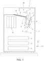
FIG. 1 is a schematic configuration diagram of an entire recording apparatus according to a first embodiment. -
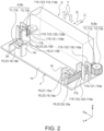
FIG. 2 is a schematic perspective view of a key portion showing an "attached" state of a recording section according to the first embodiment. -
FIG. 3 is a schematic perspective view of the key portion showing a "detached" state of the recording section according to the first embodiment. -
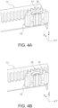
FIG. 4A is a schematic perspective view of a key portion for explaining meshing between a reference tooth of a pinion and a reference groove of a rack. -
FIG. 4B is another schematic perspective view of the key portion for explaining the meshing between the reference tooth of the pinion and the reference groove of the rack. -
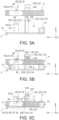
FIG. 5A is a diagram of key portion configuration showing reattachment of the recording section in the first embodiment. -
FIG. 5B is an another diagram of key portion configuration showing the reattachment of the recording section in the first embodiment. -
FIG. 5C is a still another diagram of key portion configuration showing the reattachment of the recording section in the first embodiment. -
FIG. 6 is a schematic configuration diagram of a key portion of the recording section of the recording apparatus according to the first embodiment. - The present disclosure will be described briefly. In order to overcome the above described problem, a recording apparatus according to a first aspect of the present disclosure includes: a transport path that is provided in an apparatus main body to transport a medium; a recording section that is movable in a direction toward and away from the transport path; and a rack and pinion mechanism that moves the recording section in the direction toward and away from the transport path, wherein: the rack and pinion mechanism includes a rack that is provided to the recording section and that is formed along a movement direction of the recording section and a pinion that is provided to the apparatus main body and that meshes with the rack, the recording section is attachable to and detachable from the apparatus main body, and a positioning section is provided to the recording section and the apparatus main body for positioning so that a reference tooth of the pinion meshes with a reference groove of the rack when the recording section is returned from a detached state to an attached state.
- According to this aspect, the positioning section is provided to the recording section and to the apparatus main body for positioning so that the reference tooth of the pinion meshes with the reference groove of the rack when the recording section, which can be attached to or detached from the apparatus main body, is returned from the detached state to the attached state. With this configuration, when the recording section is detached from the apparatus main body and then reattached, the rack and the pinion mesh with each other in a state in which the reference tooth of the pinion and the reference groove of the rack are positioned by the positioning section so as to mesh. Therefore, it is possible to easily reattach the recording head to the apparatus main body in a state in which the movement of the recording head can be normally controlled.
- The recording apparatus according to a second aspect of this disclosure is an aspect according to the first aspect, wherein the positioning section includes a convex portion disposed on one of the recording section and the apparatus main body and a guide portion disposed on the other of the recording section and the apparatus main body to guide and position the convex portion when returning the recording section to the attached state.
- According to this aspect, the positioning section is composed of the convex portion and the guide portion that guides the convex portion to perform positioning when the recording section is returned to the attached state. Therefore, the positioning section can be realized with a simple structure.
- The recording apparatus according to a third aspect of this disclosure is an aspect according to the second aspect, wherein the guide portion releases the state of guiding the convex portion in the attached state of the recording section. Here, "releases the state of guiding the convex portion" in "the guide portion releases the state of guiding the convex portion in the attached state of the recording section" means a state in which the rack is able to move by rotation of the pinion.
- According to this aspect, the guide portion releases the state of guiding the convex portion in the attached state of the recording section. Thus, the rack can be moved by the rotation of the pinion, and the movement of the recording section can be controlled.
- The recording apparatus according to a fourth aspect of this disclosure is an aspect according to the second aspect or to the third aspect, wherein the convex portion and the guide portion are disposed so as to be visible from an upstream side in an attachment direction when the recording section is moved in the attachment direction.
- According to this aspect, the convex portion and the guide portion are disposed so as to be visible from an upstream side in the attachment direction when the recording section is moved in the attachment direction. Therefore, it is possible to guide the convex portion to the guide portion while visually checking, and to easily align the convex portion with the guide portion.
- The recording apparatus according to a fifth aspect of this disclosure is an aspect according to any one of the second aspect to the fourth aspect, wherein the rack is disposed on a side surface portion of the recording section in a width direction, which intersects the movement direction of the recording section and the pinion is disposed at a position to mesh with the rack.
- According to this aspect, since the rack and the pinion mesh at the side surface portion of the recording section, the size of the recording section relative to the medium transport direction can be small.
- The recording apparatus according to a sixth aspect of this disclosure is an aspect according to any one of the second aspect to the fifth aspect, wherein rack and pinion mechanisms and positioning sections are disposed on both side surface portions of the recording section in the width direction, which intersects the movement direction of the recording section.
- According to this aspect, the rack and pinion mechanisms are provided on both side surface portions of the recording section. This makes it possible to move the recording section in the movement direction while appropriately maintaining the posture of the recording section during movement.
- The recording apparatus according to a seventh aspect of this disclosure is an aspect according to any one of the second aspect to the sixth aspect, wherein one of the convex portion and the guide portion is integrally formed with a member that forms the rack, and the other of the convex portion and the guide portion is attachable to and detachable from the apparatus main body.
- According to this aspect, since the one of the above is integrally formed with the member that forms the rack, the number of components and assembly variations can be reduced. In addition, since the other one can be attached to and detached from the apparatus main body, it is easy to change the fixed position. Further, since the parts can be exchanged, the variations in parts can be canceled out.
- The recording apparatus according to an eighth aspect of this disclosure is an aspect according to any one of the second aspect to the seventh aspect, wherein a second positioning section, which has the same function as the positioning section, is provided to an opposite side of the rack than is the positioning section.
- According to this aspect, since the second positioning section is further provided, it is possible to prevent the recording section from rotating around the guide section as a rotation fulcrum when the detached recording section is reattached to the apparatus main body, compared to when the recording section is guided by the single positioning section.
- The recording apparatus according to a ninth aspect of this disclosure is an aspect according to the eighth aspect, wherein the second positioning section has a height position different from that of the positioning section.
- According to this aspect, since the second positioning section has a different height position from the positioning section, it is possible to prevent the recording section from being reattached in a tilted state with respect to the apparatus main body. Accordingly, it is possible to suppress meshing deviation between the rack and the pinion.
- The recording apparatus according to a tenth aspect of this disclosure is an aspect according to the eighth aspect or the ninth aspect, wherein second positioning sections are disposed on both side surface portions of the recording section in a width direction, which intersects the movement direction of the recording section.
- According to this aspect, since the second positioning sections are provided on both side surface portions of the recording section, it is possible to further prevent the recording section from rotating around the guide section as a rotation fulcrum when the detached recording portion is reattached to the apparatus main body.
- Hereinafter, the liquid ejection apparatus according to the first embodiment will be specifically described below with reference to
FIGS. 1 to 6 . In the following description, three axes orthogonal to each other are referred to as an X-axis, a Y-axis, and a Z-axis, respectively, as shown in theFIGS. 1 to 6 . The Z-axis direction corresponds to a vertical direction, that is, a direction in which gravity acts. The X-axis direction and the Y-axis direction correspond to horizontal directions. In each figure, the direction indicated by the arrows on the three axes (X, Y, Z) is the + direction of each direction, and the opposite direction is the - direction. - As shown in
FIG.1 , arecording apparatus 1 in this embodiment is an inkjet printer that prints by ejecting ink, which is a liquid, onto a medium S such as paper sheets. The medium S is stored in themedium accommodation section 2. The medium S is picked by a pickup roller, which is not shown, and sent to atransport path 3, where it is transported in a transport direction F by a plurality oftransport rollers 4 located along thetransport path 3. InFIG. 1 , only a part of thetransport rollers 4 is shown in order to avoid complication of the figure. Then, the medium S passes through a recording area of arecording section 5 located along thetransport path 3, where recording is executed. - The
recording section 5 has arecording head 6 that ejects ink. In this embodiment, therecording head 6 is a line head, but is not limited to a line head. There is aplaten 8 with an endless belt structure at a position facing therecording head 6. Theplaten 8 forms the recording area between itself and therecording head 6. The medium S that was printed on by therecording head 6 is transported along thetransport path 3 by thetransport rollers 4 and discharged to thedischarge tray 10.Reference numeral 12 is an ink accommodation section. - In this embodiment, the
transport path 3 is arranged in the apparatusmain body 7 in a state of being supported by structural members (not shown). Therecording section 5 is provided so as to be movable in a direction approaching and separating from thetransport path 3. InFIG. 1 , therecording section 5 shown in solid line is at an adjacent position near thetransport path 3, and therecording section 5 shown in broken line is at a separated position separated from thetransport path 3. Arecording section 5 performs recording at the adjacent position. Maintenance is performed on therecording head 6 of therecording section 5 at the separated position by a maintenance section (not shown). - As shown in
FIG. 2 , in this embodiment, therecording section 5 is moved in an approaching direction C and in a separating direction D with respect to thetransport path 3 by a rack and pinion mechanism 9. The rack and pinion mechanism 9 has arack 11 provided to therecording section 5 and formed along the moving directions C and D of therecording section 5, and apinion 13 provided to the apparatusmain body 7 that meshes with therack 11. Therack 11 and thepinion 13 are made of a synthetic resin material. Therack 11 is disposed on a side surface portion of therecording section 5 in the width direction (X-axis direction), which intersects with the moving directions C and D of therecording section 5. Thepinion 13 is then disposed at a position where thepinion 13 meshes with therack 11. - In this embodiment, rack and pinion mechanisms 9 are disposed on both side surface portions of the
recording section 5 in the width direction (X-axis direction), which intersects the moving directions C and D. In the description of the rack and pinion mechanism 9, when the rack and pinion mechanisms 9 located on both side surface portions are to be distinguished from each other, symbols a and b are appended to the numerical symbols, as in rack andpinion mechanisms recording section 5 is moved in the approaching direction C and in the separating direction D with respect to thetransport path 3 by the pair of rack andpinion mechanisms pinion mechanism 9a has arack 11a provided to therecording section 5 and apinion 13a provided to the apparatusmain body 7. The rack andpinion mechanism 9b has a rack 11b provided to therecording section 5 and apinion 13b provided to the apparatusmain body 7. - As shown in
FIGS. 1 and2 , therecording section 5 is configured to be attached to and detached from the apparatusmain body 7 in attach and detach directions T.FIG. 2 shows an "attached" state of therecording section 5, andFIG. 3 shows a "detached" state of therecording section 5. In this "detached" state, therack 11 and thepinion 13 do not mesh. As shown inFIG. 1 , the attach and detach directions T are slightly inclined from the Z-axis direction, which is the vertical direction in this embodiment. However, since the aforementioned inclination is practically unproblematic in the work of attaching and detaching, for the sake of simplicity, it is assumed that the attach and detach directions T are in the Z-axis direction in the explanation usingFIG. 2 and thereafter. As shown inFIG. 3 , by detaching therecording section 5 from the apparatusmain body 7, that is by putting therecoding section 5 in the aforementioned "detached" state, therecording section 5 can be treated for malfunctions and other problems. After the malfunctions or other problems are corrected, therecording section 5 is reattached to the apparatusmain body 7, that is, therecording section 5 is returned to the aforementioned "attached" state. - A positioning section 19 is provided to the
recording section 5 and to the apparatusmain body 7 for positioning to mesh areference groove 17 of therack 11 and areference tooth 15 of thepinion 13 as shown inFIG. 4A , when returning therecording section 5 from the detached state (FIG. 3 ) to the attached state (FIG. 2 ).FIG. 4B shows a state in which thereference tooth 15 of thepinion 13 is not properly meshed with thereference groove 17 of therack 11, that is, a state in which they are meshed out of alignment. The reason why thereference tooth 15 of thepinion 13 and thereference groove 17 of therack 11 need to mesh properly is that this is necessary to control the movement of therecording section 5 by the rack and pinion mechanism 9. This is because if the teeth of thepinion 13 mesh with the groove of therack 11 at an arbitrary position, movement control cannot be performed correctly. - In this embodiment, as shown in
FIGS. 2 and3 , positioning sections 19, in the same way as rack and pinion mechanisms 9, are also disposed on both side surface portions of therecording section 5 in the width direction (X-axis direction), which intersects the movement directions C and D of therecording section 5. The positioning section 19a of the rack andpinion mechanism 9a and the positioning section 19b of the rack andpinion mechanism 9b are arranged in plane symmetry. From the viewpoint of simplifying design and manufacturing, the positioning section 19a and the positioning section 19b are made with the same structure. Of course, they are not limited to the same structure. - In this embodiment, the positioning section 19 has a convex portion 21 disposed on the apparatus
main body 7, and a guide portion 23 disposed on therecording section 5 that guides the convex portion 21 to perform the positioning when returning therecording section 5 to the "attached" state. The positioning section 19 may be arranged in the reverse configuration, with the guide portion 23 disposed on the apparatusmain body 7 and the convex portion 21 disposed on therecording section 5. Specifically, as shown inFIGS. 2 and3 , the convex portion 21 is formed integrally with a fixingplate 16 fixed to abase portion 14, which constitutes a part of the apparatusmain body 7. The shape of the convex portion 21 is not limited to the cylindrical shape with a circular cross section shown in the figures, but can also be a downward-facing U-shape in cross section with a curved outer surface, or other shape. - The guide portion 23 is integrally formed with a member in which the
rack 11 is formed, which is disposed on therecording section 5. The guide portion 23 protrudes from a surface 30 (FIGS. 2 and3 ) on which therack 11 is not formed. The guide portion 23 has a slit 22 (FIG. 5 ) for passing and guiding the convex portion 21. In this embodiment, theslit 22 is formed by a pair of opposing plates 18 and 20. Of course, theslit 22 is not limited to a structure formed by the opposing plates 18 and 20. The guide for the positioning is performed by the convex portion 21 passing through theslit 22 of the guide portion 23 in the Z-axis direction, and this guide brings thereference tooth 15 of thepinion 13 and thereference groove 17 of therack 11 into a meshed state. InFIGS. 2 and3 , the pair of opposing plates 18 and 20, which form the guide portion 23, are shown as simple plate shapes. However, as shown inFIG. 5 , it is desirable to have a reverse tapered shape with awidened diameter portion 24 on the lower side (-Z direction) of theslit 22 portion. This is because the convex portion 21 can be easily guided to theslit 22 by the presence of the wideneddiameter portion 24. - In this embodiment, as shown in
FIG. 5C , the guide portion 23 is configured to release the state of guiding the convex portion 21 in the "attached" state of therecording section 5. Specifically, the convex portion 21 is configured so that after passing through theslit 22 of the guide portion 23 in the -Z direction, as shown inFIG. 5C , it enters a positional relationship that does not interfere in the height direction with one of the opposing plates 18 comprising the guide portion 23. That is, in the state shown inFIG. 5C , therack 11 can move in the -Y direction by rotation of thepinion 13. - In this embodiment, as shown in
FIGS. 2 and3 , the guide portion 23 is integrally formed with the member on which therack 11 is formed. On the other hand, the convex portion 21 is formed so as to be attachable to and detachable from the apparatusmain body 7. Specifically, the fixingplate 16, in which the convex portion 21 is integrally formed, can be attached to and detached from thebase portion 14, which constitutes a part of the apparatusmain body 7, from the back of thebase portion 14. Alternatively, the guide portion 23 may be detachably attached to thebase portion 14, and the convex portion 21 may be integrally form with the member on which therack 11 is formed. Further, in this embodiment, the convex portion 21 and the guide portion 23 are disposed so as to be visible from the upstream side in the "attachment" direction while therecording section 5 is moving in the "attachment" direction. - In this embodiment, as shown in
FIGS. 2 and3 , a second positioning section 119, which has the same function as the positioning section 19, is provided to the opposite side of therack 11 than is the positioning section 19. Since the second positioning section 119 has the same function as the positioning section 19, the second positioning section 119 has members with similar functions corresponding to the convex portion 21, the guide portion 23, and other parts that make up the positioning section 19. Therefore, in the following description, each member of the second positioning section 119 will be denoted by a reference numeral obtained by adding 100 to the reference numeral of each member of the positioning section 19, that is, will be denoted in association with each member of the positioning section 19. For example, the convex portion 121 of the second positioning section 119 corresponds to the convex portion 21 of the positioning section 19. This is assumed to be an explanation that the convex portion 121 is provided with the same function as the convex portion 21, and the previously mentioned explanations of similar matters will be omitted. Further, the guide portion 123 of the second positioning section 119 corresponds to the guide portion 23 of the positioning section 19. This is assumed to be an explanation that the guide portion 123 is provided with the same function as the guide portion 23, and the previously mentioned explanations of similar matters will be omitted. The same applies to other components. Each corresponding component of both the second positioning section 119 and the positioning section 19 has a common function, but the shapes need not to be identical. - Second positioning sections 119, like the positioning sections 19, are disposed on both side surface portions of the
recording section 5. That is, as shown inFIGS. 2 and3 , the second positioning section 119a and the second positioning section 119b are disposed. In this embodiment, the second positioning section 119 has the guide portion 123 disposed on the apparatusmain body 7 and the convex portion 121 disposed on therecording section 5, contrary to the positioning section 19. Of course, like the positioning section 19, the structure may be such that the convex portion 121 is disposed on the apparatusmain body 7 and the guide portion 123 is disposed on therecording section 5. In this embodiment, since the convex portion 121 is disposed on therecording section 5 side, the following configuration is adopted so that therecording section 5 can move in the -Y direction after the convex portion 121 passes through theslit 122 in the -Z direction and enters the state shown inFIG. 5C . That is, the opposing plate 118 is configured so that a portion thereof below the portion of the opposing plate 118 that constitutes theslit 122, does not interfere with the convex portion 121. That is, in the state shown inFIG. 5C , therack 11 can move in the -Y direction by rotation of thepinion 13. - In this embodiment, the second positioning section 119 is configured to have a different height position from the positioning section 19. Here, as shown in
FIGS. 5A to 5C , the second positioning section 119 is disposed at a position higher than the positioning section 19. The height position of the positioning section 19 is the position of the convex portion 21, and the height position of the second positioning section 119 is the position of aslit 122. The second positioning section 119 may be disposed at the same height position as the positioning section 19. - In
FIGS. 2 and3 , the pair of opposing plates 118 and 120, which form the guide portion 123, are shown as a simple plate shapes. However, as shown inFIG. 5 , it is desirable to have a reverse tapered shape with wideneddiameter portion 124 on the upper side (+ Z direction) of theslit 122 portion. This is because the convex portion 121 can be easily guided to theslit 122 by the presence of the wideneddiameter portion 124. - In this embodiment, as shown in
FIG. 6 , thepinions 13 also mesh with another racks 26. If the positions of theracks 26 are fixed and thepinions 13 are configured to be movable, rotation of thepinions 13 moves theracks 11 on therecording section 5 side in the - Y direction and simultaneously thepinions 13 move in the -Y direction over the other racks 26. This increases the moving distance of therecording section 5 in the -Y direction. In this structure, it is necessary that thereference tooth 15 of thepinion 13 and thereference groove 17 of therack 11 correctly mesh. When controlling the movement of therecording section 5 by the rack and pinion mechanism 9, if the tooth of thepinion 13 and the groove of therack 11 do not mesh correctly as shown inFIG. 4A , but instead mesh at a misaligned position as shown inFIG. 4B , the movement control cannot be performed correctly. Specifically, the problem occurs that a movement distance of therecording section 5 in the -Y direction changes for the same rotation amount of thepinion 13. - In
FIG. 1 , anupper surface portion 28 of the apparatusmain body 7 is opened, then therecording section 5 is lifted upward (T direction) and removed. After thatrecording section 5 has been repaired, the operator moves therecording section 5, which is in the "detached" state shown inFIGS. 3 and5A , downward (-Z direction). As shown inFIG. 5B , before therack 11 portion of therecording section 5 meshes with thepinion 13 on the apparatusmain body 7 side, a positioning is performed by the positioning section 19. Specifically, the convex portion 21 on the apparatusmain body 7 side contacts the wideneddiameter portion 24 of the guide portion 23 on therecording section 5 side, and the convex portion 21 is guided into theslit 22. As a result, thereference tooth 15 of thepinion 13 and thereference groove 17 of therack 11 enter a meshed state. Therack 11 and thepinion 13 may mesh at the same time as the aforementioned positioning by the positioning section 19 is performed. When therecording section 5 is moved further downward, it returns to the original "attached" state shown inFIG. 5C . In this "attached" state, the guide portion 23 releases the state of guiding the convex portion 21. That is, in the state shownFIG. 5C , therack 11 can move in the -Y direction by the rotation of thepinion 13. - The second positioning section 119 acts in the same way as the positioning section 19. That is, the second positioning section 119 is configured to start positioning at the same timing that the positioning section 19 starts positioning. The above timing does not have to strictly coincide. As shown in
FIG. 5B , before therack 11 portion of therecording section 5 meshes with thepinion 13 on the apparatusmain body 7 side, the positioning is performed by the positioning section 119. Specifically, the convex portion 121 on therecording section 5 side contacts the wideneddiameter portion 124 of the guide portion 123 on the apparatusmain body 7 side, and the convex portion 121 is guided into theslit 122. As a result, thereference tooth 15 of thepinion 13 and thereference groove 17 of therack 11 enter a meshed state. Therack 11 and thepinion 13 may mesh at the same time as the aforementioned positioning by the second positioning section 119 is performed. When therecording section 5 is moved further downward, it returns to the original "attached" state shown inFIG. 5C . In this "attached" state, the guide portion 123 releases the state of guiding the convex portion 121. That is, in the state shownFIG. 5C , therack 11 can move in the -Y direction by the rotation of thepinion 13. Although not shown, bearings are provided on both side surface portions of therecording section 5, and guide rails are provided on the apparatusmain body 7. When therecording section 5 is reattached, before the positioning by the positioning section 19 or the like is started, therecording section 5 is supported so that it can move in the movement direction with the bearings guided by the guide rails. Therecording section 5 is guided by the guide rails and the bearings so that positioning by the positioning section 19 or the like is easily started. -
- (1) According to this embodiment, the positioning section 19 is provided to the
recording section 5 and on the apparatusmain body 7 and, when therecording section 5, which can be attached to and detached from the apparatusmain body 7, is returned from the "detached" state to the "attached" state, positions thereference tooth 15 of thepinion 13 and thereference groove 17 of therack 11 so as to mesh. As a result, when therecording section 5 is detached from the apparatusmain body 7 and attached again, therack 11 and thepinion 13 mesh with each other in a state which is positioned by the positioning section 19 so that thereference tooth 15 of thepinion 13 and thereference groove 17 of therack 11 mesh. Therefore, the recording head can be easily reattached to the apparatusmain body 7 in a state in which the movement of therecording head 6 can be controlled normally. - (2) Further according to this embodiment, the positioning section 19 includes the convex portion 21, and the guide portion 23 that guides the convex portion 21 and performs the positioning when the
recording section 5 is being returned to the "attached" state. Thus, the positioning section 19 can be realized with a simple structure. - (3) According to this embodiment, the guide portion 23 releases the state of guiding the convex portion 21 in the "attached" state of the
recording section 5. Thus, therack 11 can be moved by the rotation of thepinion 13, and the movement of therecording section 5 can be controlled. - (4) According to this embodiment, the convex portion 21 and the guide portion 23 are disposed so as to be visible from the upstream side in the "attachment" direction when the
recording section 5 is moved in the "attachment" direction. As a result, it is possible to guide the convex portion 21 to the guide portion 23 while visually checking the convex portion 21, and to easily align the convex portion 21 with the guide portion 23. - (5) According to this embodiment, since the
rack 11 and thepinion 13 mesh with each other at the side surface portion of therecording section 5, the size of therecording section 5 with respect to the medium transport direction F can be small. - (6) According to this embodiment, the rack and pinion mechanisms 19 are provided on both side surface portions of the
recording section 5. As a result, therecording section 5 can be moved in the movement directions C and D while appropriately maintaining the posture of therecording section 5 during movement. - (7) According to this embodiment, one of the convex portion 21 and the guide portion 23 is integrally formed with the member on which the
rack 11 is formed. Therefore, the number of components can be reduced, and variation in assembly can be reduced. Further, since the other of the convex portion 21 and the guide portion 23 can be attached to and detached from the apparatusmain body 7, it is easy to change the fixed position. Further, since the parts can be exchanged, the variations in parts can be canceled out. - (8) According to this embodiment, the second positioning section 119 is further provided, so that when the
detached recording section 5 is reattached in the apparatusmain body 7, therecording section 5 is prevented from rotating around the guide portion 23 as a rotation fulcrum, compared to when guided by a single positioning section. - (9) According to this embodiment, the second positioning section 119 has a different height position from the positioning section 19, which can prevent the
recording section 5 from being reattached in a tilted state with respect to the apparatusmain body 7. Accordingly, it is possible to suppress the meshing deviation between therack 11 and thepinion 13. - (10) According to this embodiment, since the second positioning sections 119 are provided on both side surface portions of the
recording section 5, it is possible to further prevent therecording portion 5 from rotating around the guide portion 123 as a rotation fulcrum when thedetached recording section 5 is reattached to the apparatusmain body 7. - The recording apparatus according to this disclosure basically has the configuration of the embodiment described above, but it is needless to say that a partial change, omission, or the like of the configuration can be made without departing from the scope of the present disclosure. In the above embodiment, the structure with the positioning section 19 and the second positioning section 119 is described, but it is not limited to this, and a structure in which only one of the positioning section 19 and the second positioning section 119 may be provided. Further, the specific structure of the positioning section 19 is not limited to the structure of the convex portion 21 and the guide portion 23 described above. Any structure may be employed as long as the
reference tooth 15 of thepinion 13 and thereference groove 17 of therack 11 can be positioned so as to mesh with each other.
Claims (10)
- A recording apparatus comprising:a transport path that is provided in an apparatus main body to transport a medium;a recording section that is movable in a direction toward and away from the transport path; anda rack and pinion mechanism that moves the recording section in the direction toward and away from the transport path, wherein:the rack and pinion mechanism includesa rack that is provided to the recording section and that is formed along a movement direction of the recording section anda pinion that is provided to the apparatus main body and that meshes with the rack,the recording section is attachable to and detachable from the apparatus main body, anda positioning section is provided to the recording section and the apparatus main body for positioning so that a reference tooth of the pinion meshes with a reference groove of the rack when the recording section is returned from a detached state to an attached state.
- The recording apparatus according to claim 1, wherein:
the positioning section includesa convex portion disposed on one of the recording section and the apparatus main body anda guide portion disposed on the other of the recording section and the apparatus main body to guide and position the convex portion when returning the recording section to the attached state. - The recording apparatus according to claim 2, wherein:
the guide portion releases the state of guiding the convex portion in the attached state of the recording section. - The recording apparatus according to claim 2 or claim 3, wherein:
the convex portion and the guide portion are disposed so as to be visible from an upstream side in an attachment direction when the recording section is moved in the attachment direction. - The recording apparatus according to any one of claims 2 to 4, wherein:the rack is disposed on a side surface portion of the recording section in a width direction, which intersects the movement direction of the recording section andthe pinion is disposed at a position to mesh with the rack.
- The recording apparatus according to any one of claims 2 to 5, wherein:
rack and pinion mechanisms and positioning sections are disposed on both side surface portions of the recording section in the width direction, which intersects the movement direction of the recording section. - The recording apparatus according to any one of claims 2 to 6 , wherein:one of the convex portion and the guide portion is integrally formed with a member that forms the rack, andthe other of the convex portion and the guide portion is attachable to and detachable from the apparatus main body.
- The recording apparatus according to any one of claims 1 to 7, wherein:
a second positioning section, which has the same function as the positioning section, is provided to an opposite side of the rack than is the positioning section. - The recording apparatus according to claim 8, wherein:
the second positioning section has a height position different from that of the positioning section. - The recording apparatus according to claim 8 or claim 9, wherein:
second positioning sections are disposed on both side surface portions of the recording section in a width direction, which intersects the movement direction of the recording section.
Applications Claiming Priority (1)
| Application Number | Priority Date | Filing Date | Title |
|---|---|---|---|
| JP2022054082A JP7846452B2 (en) | 2022-03-29 | 2022-03-29 | Recording device |
Publications (2)
| Publication Number | Publication Date |
|---|---|
| EP4253071A1 true EP4253071A1 (en) | 2023-10-04 |
| EP4253071B1 EP4253071B1 (en) | 2024-08-07 |
Family
ID=85776008
Family Applications (1)
| Application Number | Title | Priority Date | Filing Date |
|---|---|---|---|
| EP23164286.9A Active EP4253071B1 (en) | 2022-03-29 | 2023-03-27 | Recording apparatus |
Country Status (4)
| Country | Link |
|---|---|
| US (1) | US20230311540A1 (en) |
| EP (1) | EP4253071B1 (en) |
| JP (1) | JP7846452B2 (en) |
| CN (1) | CN116890535A (en) |
Citations (2)
| Publication number | Priority date | Publication date | Assignee | Title |
|---|---|---|---|---|
| JP2012158036A (en) | 2011-01-31 | 2012-08-23 | Brother Industries Ltd | Recorder |
| JP2022054082A (en) | 2020-09-25 | 2022-04-06 | ミツミ電機株式会社 | Parking detection device and parking detection method |
Family Cites Families (9)
| Publication number | Priority date | Publication date | Assignee | Title |
|---|---|---|---|---|
| US2376161A (en) * | 1944-01-17 | 1945-05-15 | Selas Corp Of America | Tooth gearing |
| JP5678290B2 (en) * | 2010-04-27 | 2015-02-25 | 株式会社デュプロ | Inkjet recording device |
| US8430585B2 (en) * | 2010-09-17 | 2013-04-30 | Hewlett-Packard Development Company, L.P. | Print bar lift and method |
| US9061531B2 (en) * | 2013-11-15 | 2015-06-23 | Memjet Technology Ltd. | Modular printer having narrow print zone |
| JP7243454B2 (en) * | 2019-05-30 | 2023-03-22 | セイコーエプソン株式会社 | Media ejection device, media processing device, and recording system |
| JP7482368B2 (en) * | 2020-01-31 | 2024-05-14 | セイコーエプソン株式会社 | Recording device |
| JP7452043B2 (en) * | 2020-01-31 | 2024-03-19 | セイコーエプソン株式会社 | recording device |
| CN214631836U (en) * | 2020-12-02 | 2021-11-09 | 珠海优特智厨科技有限公司 | Door opening and closing structure and blanking device |
| CN113915304A (en) * | 2021-11-09 | 2022-01-11 | 罗森伯格技术有限公司 | Transmission and phase-shifting assembly |
-
2022
- 2022-03-29 JP JP2022054082A patent/JP7846452B2/en active Active
-
2023
- 2023-03-27 CN CN202310307971.XA patent/CN116890535A/en active Pending
- 2023-03-27 EP EP23164286.9A patent/EP4253071B1/en active Active
- 2023-03-28 US US18/191,653 patent/US20230311540A1/en active Pending
Patent Citations (2)
| Publication number | Priority date | Publication date | Assignee | Title |
|---|---|---|---|---|
| JP2012158036A (en) | 2011-01-31 | 2012-08-23 | Brother Industries Ltd | Recorder |
| JP2022054082A (en) | 2020-09-25 | 2022-04-06 | ミツミ電機株式会社 | Parking detection device and parking detection method |
Also Published As
| Publication number | Publication date |
|---|---|
| US20230311540A1 (en) | 2023-10-05 |
| EP4253071B1 (en) | 2024-08-07 |
| JP2023146730A (en) | 2023-10-12 |
| CN116890535A (en) | 2023-10-17 |
| JP7846452B2 (en) | 2026-04-15 |
Similar Documents
| Publication | Publication Date | Title |
|---|---|---|
| US9108442B2 (en) | Image forming apparatus | |
| JP5678290B2 (en) | Inkjet recording device | |
| JP2009143071A (en) | Liquid ejection device | |
| JP2014065293A (en) | Image forming apparatus | |
| JP2011218761A (en) | Image recording apparatus, and method for moving head holder of the same | |
| CN101234564B (en) | Image forming device | |
| EP4253071B1 (en) | Recording apparatus | |
| US12083806B2 (en) | Recording apparatus | |
| US20170087886A1 (en) | Ink-jet recording apparatus | |
| KR20070094539A (en) | Feeding device of pattern sewing machine | |
| USRE48390E1 (en) | Liquid jetting apparatus | |
| US11059307B2 (en) | Printing apparatus and moving method for support portion | |
| EP4209353A1 (en) | Recording apparatus | |
| JP2023089492A (en) | Liquid discharge device | |
| JP5110023B2 (en) | Liquid discharge line head and liquid discharge apparatus | |
| US20250326237A1 (en) | Recording device | |
| US11872816B2 (en) | Recording apparatus | |
| US20260061750A1 (en) | Liquid ejection apparatus | |
| US20240066899A1 (en) | Recording device | |
| US11628671B2 (en) | Printing apparatus | |
| US20230211619A1 (en) | Recording apparatus | |
| JP5699354B2 (en) | Inkjet recording apparatus and head unit | |
| JP2012218339A (en) | Printer | |
| JP2017074747A (en) | Recording device | |
| JP2022110677A (en) | Image reading device, multifunction device, and method for manufacturing multifunction device |
Legal Events
| Date | Code | Title | Description |
|---|---|---|---|
| PUAI | Public reference made under article 153(3) epc to a published international application that has entered the european phase |
Free format text: ORIGINAL CODE: 0009012 |
|
| STAA | Information on the status of an ep patent application or granted ep patent |
Free format text: STATUS: THE APPLICATION HAS BEEN PUBLISHED |
|
| AK | Designated contracting states |
Kind code of ref document: A1 Designated state(s): AL AT BE BG CH CY CZ DE DK EE ES FI FR GB GR HR HU IE IS IT LI LT LU LV MC ME MK MT NL NO PL PT RO RS SE SI SK SM TR |
|
| STAA | Information on the status of an ep patent application or granted ep patent |
Free format text: STATUS: REQUEST FOR EXAMINATION WAS MADE |
|
| 17P | Request for examination filed |
Effective date: 20240118 |
|
| RBV | Designated contracting states (corrected) |
Designated state(s): AL AT BE BG CH CY CZ DE DK EE ES FI FR GB GR HR HU IE IS IT LI LT LU LV MC ME MK MT NL NO PL PT RO RS SE SI SK SM TR |
|
| GRAP | Despatch of communication of intention to grant a patent |
Free format text: ORIGINAL CODE: EPIDOSNIGR1 |
|
| STAA | Information on the status of an ep patent application or granted ep patent |
Free format text: STATUS: GRANT OF PATENT IS INTENDED |
|
| INTG | Intention to grant announced |
Effective date: 20240319 |
|
| GRAS | Grant fee paid |
Free format text: ORIGINAL CODE: EPIDOSNIGR3 |
|
| GRAA | (expected) grant |
Free format text: ORIGINAL CODE: 0009210 |
|
| STAA | Information on the status of an ep patent application or granted ep patent |
Free format text: STATUS: THE PATENT HAS BEEN GRANTED |
|
| AK | Designated contracting states |
Kind code of ref document: B1 Designated state(s): AL AT BE BG CH CY CZ DE DK EE ES FI FR GB GR HR HU IE IS IT LI LT LU LV MC ME MK MT NL NO PL PT RO RS SE SI SK SM TR |
|
| REG | Reference to a national code |
Ref country code: GB Ref legal event code: FG4D |
|
| REG | Reference to a national code |
Ref country code: CH Ref legal event code: EP |
|
| REG | Reference to a national code |
Ref country code: DE Ref legal event code: R096 Ref document number: 602023000334 Country of ref document: DE |
|
| REG | Reference to a national code |
Ref country code: IE Ref legal event code: FG4D |
|
| REG | Reference to a national code |
Ref country code: LT Ref legal event code: MG9D |
|
| REG | Reference to a national code |
Ref country code: NL Ref legal event code: MP Effective date: 20240807 |
|
| PG25 | Lapsed in a contracting state [announced via postgrant information from national office to epo] |
Ref country code: NO Free format text: LAPSE BECAUSE OF FAILURE TO SUBMIT A TRANSLATION OF THE DESCRIPTION OR TO PAY THE FEE WITHIN THE PRESCRIBED TIME-LIMIT Effective date: 20241107 |
|
| REG | Reference to a national code |
Ref country code: AT Ref legal event code: MK05 Ref document number: 1710530 Country of ref document: AT Kind code of ref document: T Effective date: 20240807 |
|
| PG25 | Lapsed in a contracting state [announced via postgrant information from national office to epo] |
Ref country code: PL Free format text: LAPSE BECAUSE OF FAILURE TO SUBMIT A TRANSLATION OF THE DESCRIPTION OR TO PAY THE FEE WITHIN THE PRESCRIBED TIME-LIMIT Effective date: 20240807 Ref country code: NL Free format text: LAPSE BECAUSE OF FAILURE TO SUBMIT A TRANSLATION OF THE DESCRIPTION OR TO PAY THE FEE WITHIN THE PRESCRIBED TIME-LIMIT Effective date: 20240807 Ref country code: PT Free format text: LAPSE BECAUSE OF FAILURE TO SUBMIT A TRANSLATION OF THE DESCRIPTION OR TO PAY THE FEE WITHIN THE PRESCRIBED TIME-LIMIT Effective date: 20241209 Ref country code: GR Free format text: LAPSE BECAUSE OF FAILURE TO SUBMIT A TRANSLATION OF THE DESCRIPTION OR TO PAY THE FEE WITHIN THE PRESCRIBED TIME-LIMIT Effective date: 20241108 Ref country code: FI Free format text: LAPSE BECAUSE OF FAILURE TO SUBMIT A TRANSLATION OF THE DESCRIPTION OR TO PAY THE FEE WITHIN THE PRESCRIBED TIME-LIMIT Effective date: 20240807 |
|
| PG25 | Lapsed in a contracting state [announced via postgrant information from national office to epo] |
Ref country code: BG Free format text: LAPSE BECAUSE OF FAILURE TO SUBMIT A TRANSLATION OF THE DESCRIPTION OR TO PAY THE FEE WITHIN THE PRESCRIBED TIME-LIMIT Effective date: 20240807 |
|
| PG25 | Lapsed in a contracting state [announced via postgrant information from national office to epo] |
Ref country code: LV Free format text: LAPSE BECAUSE OF FAILURE TO SUBMIT A TRANSLATION OF THE DESCRIPTION OR TO PAY THE FEE WITHIN THE PRESCRIBED TIME-LIMIT Effective date: 20240807 |
|
| PG25 | Lapsed in a contracting state [announced via postgrant information from national office to epo] |
Ref country code: AT Free format text: LAPSE BECAUSE OF FAILURE TO SUBMIT A TRANSLATION OF THE DESCRIPTION OR TO PAY THE FEE WITHIN THE PRESCRIBED TIME-LIMIT Effective date: 20240807 Ref country code: IS Free format text: LAPSE BECAUSE OF FAILURE TO SUBMIT A TRANSLATION OF THE DESCRIPTION OR TO PAY THE FEE WITHIN THE PRESCRIBED TIME-LIMIT Effective date: 20241207 |
|
| PG25 | Lapsed in a contracting state [announced via postgrant information from national office to epo] |
Ref country code: HR Free format text: LAPSE BECAUSE OF FAILURE TO SUBMIT A TRANSLATION OF THE DESCRIPTION OR TO PAY THE FEE WITHIN THE PRESCRIBED TIME-LIMIT Effective date: 20240807 |
|
| PG25 | Lapsed in a contracting state [announced via postgrant information from national office to epo] |
Ref country code: RS Free format text: LAPSE BECAUSE OF FAILURE TO SUBMIT A TRANSLATION OF THE DESCRIPTION OR TO PAY THE FEE WITHIN THE PRESCRIBED TIME-LIMIT Effective date: 20241107 Ref country code: ES Free format text: LAPSE BECAUSE OF FAILURE TO SUBMIT A TRANSLATION OF THE DESCRIPTION OR TO PAY THE FEE WITHIN THE PRESCRIBED TIME-LIMIT Effective date: 20240807 |
|
| PG25 | Lapsed in a contracting state [announced via postgrant information from national office to epo] |
Ref country code: RS Free format text: LAPSE BECAUSE OF FAILURE TO SUBMIT A TRANSLATION OF THE DESCRIPTION OR TO PAY THE FEE WITHIN THE PRESCRIBED TIME-LIMIT Effective date: 20241107 Ref country code: PT Free format text: LAPSE BECAUSE OF FAILURE TO SUBMIT A TRANSLATION OF THE DESCRIPTION OR TO PAY THE FEE WITHIN THE PRESCRIBED TIME-LIMIT Effective date: 20241209 Ref country code: PL Free format text: LAPSE BECAUSE OF FAILURE TO SUBMIT A TRANSLATION OF THE DESCRIPTION OR TO PAY THE FEE WITHIN THE PRESCRIBED TIME-LIMIT Effective date: 20240807 Ref country code: NO Free format text: LAPSE BECAUSE OF FAILURE TO SUBMIT A TRANSLATION OF THE DESCRIPTION OR TO PAY THE FEE WITHIN THE PRESCRIBED TIME-LIMIT Effective date: 20241107 Ref country code: NL Free format text: LAPSE BECAUSE OF FAILURE TO SUBMIT A TRANSLATION OF THE DESCRIPTION OR TO PAY THE FEE WITHIN THE PRESCRIBED TIME-LIMIT Effective date: 20240807 Ref country code: LV Free format text: LAPSE BECAUSE OF FAILURE TO SUBMIT A TRANSLATION OF THE DESCRIPTION OR TO PAY THE FEE WITHIN THE PRESCRIBED TIME-LIMIT Effective date: 20240807 Ref country code: IS Free format text: LAPSE BECAUSE OF FAILURE TO SUBMIT A TRANSLATION OF THE DESCRIPTION OR TO PAY THE FEE WITHIN THE PRESCRIBED TIME-LIMIT Effective date: 20241207 Ref country code: HR Free format text: LAPSE BECAUSE OF FAILURE TO SUBMIT A TRANSLATION OF THE DESCRIPTION OR TO PAY THE FEE WITHIN THE PRESCRIBED TIME-LIMIT Effective date: 20240807 Ref country code: GR Free format text: LAPSE BECAUSE OF FAILURE TO SUBMIT A TRANSLATION OF THE DESCRIPTION OR TO PAY THE FEE WITHIN THE PRESCRIBED TIME-LIMIT Effective date: 20241108 Ref country code: FI Free format text: LAPSE BECAUSE OF FAILURE TO SUBMIT A TRANSLATION OF THE DESCRIPTION OR TO PAY THE FEE WITHIN THE PRESCRIBED TIME-LIMIT Effective date: 20240807 Ref country code: ES Free format text: LAPSE BECAUSE OF FAILURE TO SUBMIT A TRANSLATION OF THE DESCRIPTION OR TO PAY THE FEE WITHIN THE PRESCRIBED TIME-LIMIT Effective date: 20240807 Ref country code: BG Free format text: LAPSE BECAUSE OF FAILURE TO SUBMIT A TRANSLATION OF THE DESCRIPTION OR TO PAY THE FEE WITHIN THE PRESCRIBED TIME-LIMIT Effective date: 20240807 Ref country code: AT Free format text: LAPSE BECAUSE OF FAILURE TO SUBMIT A TRANSLATION OF THE DESCRIPTION OR TO PAY THE FEE WITHIN THE PRESCRIBED TIME-LIMIT Effective date: 20240807 |
|
| PG25 | Lapsed in a contracting state [announced via postgrant information from national office to epo] |
Ref country code: SM Free format text: LAPSE BECAUSE OF FAILURE TO SUBMIT A TRANSLATION OF THE DESCRIPTION OR TO PAY THE FEE WITHIN THE PRESCRIBED TIME-LIMIT Effective date: 20240807 Ref country code: DK Free format text: LAPSE BECAUSE OF FAILURE TO SUBMIT A TRANSLATION OF THE DESCRIPTION OR TO PAY THE FEE WITHIN THE PRESCRIBED TIME-LIMIT Effective date: 20240807 |
|
| PG25 | Lapsed in a contracting state [announced via postgrant information from national office to epo] |
Ref country code: EE Free format text: LAPSE BECAUSE OF FAILURE TO SUBMIT A TRANSLATION OF THE DESCRIPTION OR TO PAY THE FEE WITHIN THE PRESCRIBED TIME-LIMIT Effective date: 20240807 |
|
| PG25 | Lapsed in a contracting state [announced via postgrant information from national office to epo] |
Ref country code: CZ Free format text: LAPSE BECAUSE OF FAILURE TO SUBMIT A TRANSLATION OF THE DESCRIPTION OR TO PAY THE FEE WITHIN THE PRESCRIBED TIME-LIMIT Effective date: 20240807 |
|
| PG25 | Lapsed in a contracting state [announced via postgrant information from national office to epo] |
Ref country code: SK Free format text: LAPSE BECAUSE OF FAILURE TO SUBMIT A TRANSLATION OF THE DESCRIPTION OR TO PAY THE FEE WITHIN THE PRESCRIBED TIME-LIMIT Effective date: 20240807 |
|
| REG | Reference to a national code |
Ref country code: DE Ref legal event code: R097 Ref document number: 602023000334 Country of ref document: DE |
|
| PLBE | No opposition filed within time limit |
Free format text: ORIGINAL CODE: 0009261 |
|
| STAA | Information on the status of an ep patent application or granted ep patent |
Free format text: STATUS: NO OPPOSITION FILED WITHIN TIME LIMIT |
|
| 26N | No opposition filed |
Effective date: 20250508 |
|
| PG25 | Lapsed in a contracting state [announced via postgrant information from national office to epo] |
Ref country code: SE Free format text: LAPSE BECAUSE OF FAILURE TO SUBMIT A TRANSLATION OF THE DESCRIPTION OR TO PAY THE FEE WITHIN THE PRESCRIBED TIME-LIMIT Effective date: 20240807 |
|
| PG25 | Lapsed in a contracting state [announced via postgrant information from national office to epo] |
Ref country code: MC Free format text: LAPSE BECAUSE OF FAILURE TO SUBMIT A TRANSLATION OF THE DESCRIPTION OR TO PAY THE FEE WITHIN THE PRESCRIBED TIME-LIMIT Effective date: 20240807 |
|
| PG25 | Lapsed in a contracting state [announced via postgrant information from national office to epo] |
Ref country code: LU Free format text: LAPSE BECAUSE OF NON-PAYMENT OF DUE FEES Effective date: 20250327 |
|
| REG | Reference to a national code |
Ref country code: BE Ref legal event code: MM Effective date: 20250331 |
|
| PG25 | Lapsed in a contracting state [announced via postgrant information from national office to epo] |
Ref country code: BE Free format text: LAPSE BECAUSE OF NON-PAYMENT OF DUE FEES Effective date: 20250331 |
|
| PG25 | Lapsed in a contracting state [announced via postgrant information from national office to epo] |
Ref country code: IE Free format text: LAPSE BECAUSE OF NON-PAYMENT OF DUE FEES Effective date: 20250327 |
|
| PG25 | Lapsed in a contracting state [announced via postgrant information from national office to epo] |
Ref country code: IT Free format text: LAPSE BECAUSE OF FAILURE TO SUBMIT A TRANSLATION OF THE DESCRIPTION OR TO PAY THE FEE WITHIN THE PRESCRIBED TIME-LIMIT Effective date: 20240807 |
|
| PGFP | Annual fee paid to national office [announced via postgrant information from national office to epo] |
Ref country code: DE Payment date: 20260319 Year of fee payment: 4 |
|
| PG25 | Lapsed in a contracting state [announced via postgrant information from national office to epo] |
Ref country code: RO Free format text: LAPSE BECAUSE OF FAILURE TO SUBMIT A TRANSLATION OF THE DESCRIPTION OR TO PAY THE FEE WITHIN THE PRESCRIBED TIME-LIMIT Effective date: 20240807 |
|
| PGFP | Annual fee paid to national office [announced via postgrant information from national office to epo] |
Ref country code: FR Payment date: 20260323 Year of fee payment: 4 |