EP4253063A1 - Liquid storing cartridge and printer - Google Patents
Liquid storing cartridge and printer Download PDFInfo
- Publication number
- EP4253063A1 EP4253063A1 EP23162766.2A EP23162766A EP4253063A1 EP 4253063 A1 EP4253063 A1 EP 4253063A1 EP 23162766 A EP23162766 A EP 23162766A EP 4253063 A1 EP4253063 A1 EP 4253063A1
- Authority
- EP
- European Patent Office
- Prior art keywords
- supply port
- liquid
- positioning part
- positioning
- ink
- Prior art date
- Legal status (The legal status is an assumption and is not a legal conclusion. Google has not performed a legal analysis and makes no representation as to the accuracy of the status listed.)
- Granted
Links
Images





Classifications
-
- B—PERFORMING OPERATIONS; TRANSPORTING
- B41—PRINTING; LINING MACHINES; TYPEWRITERS; STAMPS
- B41J—TYPEWRITERS; SELECTIVE PRINTING MECHANISMS, i.e. MECHANISMS PRINTING OTHERWISE THAN FROM A FORME; CORRECTION OF TYPOGRAPHICAL ERRORS
- B41J29/00—Details of, or accessories for, typewriters or selective printing mechanisms not otherwise provided for
- B41J29/12—Guards, shields or dust excluders
- B41J29/13—Cases or covers
-
- B—PERFORMING OPERATIONS; TRANSPORTING
- B41—PRINTING; LINING MACHINES; TYPEWRITERS; STAMPS
- B41J—TYPEWRITERS; SELECTIVE PRINTING MECHANISMS, i.e. MECHANISMS PRINTING OTHERWISE THAN FROM A FORME; CORRECTION OF TYPOGRAPHICAL ERRORS
- B41J2/00—Typewriters or selective printing mechanisms characterised by the printing or marking process for which they are designed
- B41J2/005—Typewriters or selective printing mechanisms characterised by the printing or marking process for which they are designed characterised by bringing liquid or particles selectively into contact with a printing material
- B41J2/01—Ink jet
- B41J2/17—Ink jet characterised by ink handling
- B41J2/175—Ink supply systems ; Circuit parts therefor
- B41J2/17503—Ink cartridges
- B41J2/17506—Refilling of the cartridge
- B41J2/17509—Whilst mounted in the printer
-
- B—PERFORMING OPERATIONS; TRANSPORTING
- B41—PRINTING; LINING MACHINES; TYPEWRITERS; STAMPS
- B41J—TYPEWRITERS; SELECTIVE PRINTING MECHANISMS, i.e. MECHANISMS PRINTING OTHERWISE THAN FROM A FORME; CORRECTION OF TYPOGRAPHICAL ERRORS
- B41J2/00—Typewriters or selective printing mechanisms characterised by the printing or marking process for which they are designed
- B41J2/005—Typewriters or selective printing mechanisms characterised by the printing or marking process for which they are designed characterised by bringing liquid or particles selectively into contact with a printing material
- B41J2/01—Ink jet
- B41J2/17—Ink jet characterised by ink handling
- B41J2/175—Ink supply systems ; Circuit parts therefor
- B41J2/17503—Ink cartridges
- B41J2/1752—Mounting within the printer
-
- B—PERFORMING OPERATIONS; TRANSPORTING
- B41—PRINTING; LINING MACHINES; TYPEWRITERS; STAMPS
- B41J—TYPEWRITERS; SELECTIVE PRINTING MECHANISMS, i.e. MECHANISMS PRINTING OTHERWISE THAN FROM A FORME; CORRECTION OF TYPOGRAPHICAL ERRORS
- B41J2/00—Typewriters or selective printing mechanisms characterised by the printing or marking process for which they are designed
- B41J2/005—Typewriters or selective printing mechanisms characterised by the printing or marking process for which they are designed characterised by bringing liquid or particles selectively into contact with a printing material
- B41J2/01—Ink jet
- B41J2/17—Ink jet characterised by ink handling
- B41J2/175—Ink supply systems ; Circuit parts therefor
- B41J2/17503—Ink cartridges
- B41J2/1752—Mounting within the printer
- B41J2/17523—Ink connection
-
- B—PERFORMING OPERATIONS; TRANSPORTING
- B41—PRINTING; LINING MACHINES; TYPEWRITERS; STAMPS
- B41J—TYPEWRITERS; SELECTIVE PRINTING MECHANISMS, i.e. MECHANISMS PRINTING OTHERWISE THAN FROM A FORME; CORRECTION OF TYPOGRAPHICAL ERRORS
- B41J2/00—Typewriters or selective printing mechanisms characterised by the printing or marking process for which they are designed
- B41J2/005—Typewriters or selective printing mechanisms characterised by the printing or marking process for which they are designed characterised by bringing liquid or particles selectively into contact with a printing material
- B41J2/01—Ink jet
- B41J2/17—Ink jet characterised by ink handling
- B41J2/175—Ink supply systems ; Circuit parts therefor
- B41J2/17503—Ink cartridges
- B41J2/17526—Electrical contacts to the cartridge
- B41J2/1753—Details of contacts on the cartridge, e.g. protection of contacts
-
- B—PERFORMING OPERATIONS; TRANSPORTING
- B41—PRINTING; LINING MACHINES; TYPEWRITERS; STAMPS
- B41J—TYPEWRITERS; SELECTIVE PRINTING MECHANISMS, i.e. MECHANISMS PRINTING OTHERWISE THAN FROM A FORME; CORRECTION OF TYPOGRAPHICAL ERRORS
- B41J2/00—Typewriters or selective printing mechanisms characterised by the printing or marking process for which they are designed
- B41J2/005—Typewriters or selective printing mechanisms characterised by the printing or marking process for which they are designed characterised by bringing liquid or particles selectively into contact with a printing material
- B41J2/01—Ink jet
- B41J2/17—Ink jet characterised by ink handling
- B41J2/175—Ink supply systems ; Circuit parts therefor
- B41J2/17503—Ink cartridges
- B41J2/17543—Cartridge presence detection or type identification
- B41J2/17546—Cartridge presence detection or type identification electronically
-
- B—PERFORMING OPERATIONS; TRANSPORTING
- B41—PRINTING; LINING MACHINES; TYPEWRITERS; STAMPS
- B41J—TYPEWRITERS; SELECTIVE PRINTING MECHANISMS, i.e. MECHANISMS PRINTING OTHERWISE THAN FROM A FORME; CORRECTION OF TYPOGRAPHICAL ERRORS
- B41J2/00—Typewriters or selective printing mechanisms characterised by the printing or marking process for which they are designed
- B41J2/005—Typewriters or selective printing mechanisms characterised by the printing or marking process for which they are designed characterised by bringing liquid or particles selectively into contact with a printing material
- B41J2/01—Ink jet
- B41J2/17—Ink jet characterised by ink handling
- B41J2/175—Ink supply systems ; Circuit parts therefor
- B41J2/17503—Ink cartridges
- B41J2/17553—Outer structure
-
- B—PERFORMING OPERATIONS; TRANSPORTING
- B41—PRINTING; LINING MACHINES; TYPEWRITERS; STAMPS
- B41J—TYPEWRITERS; SELECTIVE PRINTING MECHANISMS, i.e. MECHANISMS PRINTING OTHERWISE THAN FROM A FORME; CORRECTION OF TYPOGRAPHICAL ERRORS
- B41J29/00—Details of, or accessories for, typewriters or selective printing mechanisms not otherwise provided for
- B41J29/02—Framework
Definitions
- a cartridge case described in Patent Literature 1 is provided with a first case and a second case which extend in a first direction.
- the first case is provided on a lower side of the second case, an upper side of the first case is opened, and the first case accommodates a liquid storing body in the inside of the first case.
- the second case is provided on a location above the first case so as to face the first case, and covers the first case.
- a tap supporting part which supports a tap of the liquid storing body is provided on one end part in the first direction of the first case. In a case that the liquid storing body is attached to the cartridge case, the second case is moved, relative to the first case, in a direction opposite to the one end part in the first direction so as to cause the first case to accommodate the liquid storing body.
- a liquid storing cartridge includes:
- the position of the supply port is positioned (or aligned) with respect to a supplying needle by the first positioning part and the second positioning part. Accordingly, it is possible to lower any possibility that the position of the supply port might be deviated with respect to the supplying needle, to lower any connection failure of the supply port, and to lower any possibility that the liquid might leak from the supply port.
- a printer includes the above-described liquid storing cartridge.
- the position of the supply port is positioned (aligned) with respect to a supplying needle by the first positioning part and the second positioning part. Accordingly, it is possible to lower any possibility that the position of the supply port might be deviated with respect to the supplying needle, to lower any connection failure of the supply port, and to lower any possibility that the liquid might leak from the supply port.
- FIG. 6 A left lower side, a right upper side, a right lower side, a left upper side, an upper side and a lower side of FIG. 6 are, respectively, a front side, a rear side, a right side, a left side, an upper side and a lower side of a cartridge 30.
- FIGs. 1 to 5 are drawings with the directions of the printer 1
- FIGs. 6 to 13 are drawings with the directions of the cartridge 30 or the maintenance box 300
- the cartridge 30 and the maintenance box 300 are installed in the printer 1 in a state that the front surfaces of the cartridge 30 and the maintenance box 300 are oriented to face the rear surface of the printer 1.
- the printer 1 is an ink-jet printer which performs printing on a medium having an elongated shape.
- the printer 1 prints the print data on the medium by a printing mechanism (omitted in the drawings) built in the printer 1, and discharges the medium from a discharge port 21 (to be described later on).
- the printer 1 is provided with a casing 2.
- the front wall 24 is provided on a front surface of the casing 2, and has, from the upper side toward the lower side, a first front wall 241 and a second front wall 242.
- Each of the first front wall 241 and the second front wall 242 is rectangular which is long in a left-right direction as seen from the front side.
- the first front wall 241 is provided on an upper part on the front side of the casing 2, and the second front wall 242 is provided at a location which is below the first front wall 241 and which is at the center on the front side of the casing 2.
- Each of the right wall 25, the rear wall 26 and the left wall 29 is rectangular which is long in an up-down direction.
- each of the bottom wall 27 and the upper wall 28 is rectangular which is long in a front-rear direction.
- the discharge port 21 is provided on a boundary between the first front wall 241 and the second front wall 242.
- the discharge port 21 is a rectangular opening which is long in the left-right direction as seen from the front side, and discharges a medium having printing performed thereon.
- the first front wall 241 is provided with a displaying part 3 and an operating part 4.
- the displaying part 3 displays a letter, an image, etc.
- the operating part 4 is provided on the right side with respect to the displaying part 3.
- the operating part 4 is provided with a touch panel or a plurality of buttons via which a variety of kinds of instructions are inputted.
- the printer 1 accommodates, in the inside of the casing 2, an ink-jet head 8, a cartridge 30, an ink tube 48, a conveying device 45, a partition wall 55 and a fixing unit 143.
- the cartridge 30 is accommodated in the opening part 11.
- the cartridge 30 accommodates a liquid container 100 which stores the ink in the inside thereof, and is installed in an installment part 7 of the opening part 11.
- the details of the cartridge 30 will be described later on.
- the ink tube 48 is arranged in the inside of the casing 2 and connects the installment part 7 and the ink-jet head 8.
- the ink G in the inside of the cartridge 30 is supplied, via the ink tube 48, from the cartridge 30 to the ink-jet head 8.
- the conveying device 45 is provided with the supplying part 5, conveying parts 270, 10, 15 and 19, a supporting part 80, a tension applying part 60 and a rotary body 75.
- the supplying part 5 is provided on a space which is located on the left side of the front cover 23 at the close position and which is located at a rear lower part of the printer 1 and surrounded by the partition wall 55 and the rear wall 26.
- the supplying part 5 holds a roll R.
- the supplying part 5 is provided with a shaft part 51 and a magazine 52.
- the shaft part 51 extends in the left-right direction, and is inserted into a paper tube K of the roll R.
- the magazine 52 is a supporting stand which has a shape of a letter "U" as seen from the front side.
- the magazine 52 supports both of left and right end parts of the shaft part 51 so that the shaft part 51 is rotatable about an axis extending in the left-right direction.
- the shaft part 51 is supported by the magazine 52 in a state that the shaft part 51 is detachable from the magazine 52.
- the magazine 52 is supported by the printer 1 in a state that the magazine 52 is detachable from the printer 1.
- An operator who replaces the roll R arranges the front cover 23 at the open position, takes out the magazine 52 from the inside of the casing 2 and performs a replacing operation of the roll R.
- the conveying part 270 conveys the medium M in a conveying direction F in which the medium M is conveyed from the supplying part 5 toward the ink-jet head 8 and to a retuning direction B which is opposite or reverse direction to the conveying direction F.
- the conveying direction F is a direction along the conveying route Q which is from the supplying part 5 toward the ink-jet head 8.
- a part, of the conveying direction F, from the suppling part 5 up to the tension applying part 60 is a direction which changes depending on a remaining amount of the medium M, and is generally upward.
- a part, of the conveying direction F, from the tension applying part 60 up to the discharge port 21 is generally frontward.
- the conveying part 10 is provided on the upstream side in the conveying direction F with respect to the conveying part 270, and conveys the medium in the conveying direction F and the retuning direction B.
- the conveying part 10 rotates the roll R held by the supplying part 5, conveys the medium M in the returning direction B, and takes (winds) the medium M on the roll R.
- the conveying part 10 detachably engages with the shaft part 51 of the supplying part 5.
- the conveying part 10 rotates the roll R held by the supplying part 5, conveys the medium M in the conveying direction F, and feeds the medium M from the roll R toward the ink-jet head 8.
- the supporting part 80 is provided on the upstream side in the conveying direction F with respect to the conveying part 270 and on the downstream side in the conveying direction F with respect to the conveying part 10, and supports the tension applying part 60 and the rotary body 75.
- the tension applying part 60 is provided between the conveying part 270 and the conveying part 10 in the conveying route Q.
- the tension applying part 60 is arranged at a location above the supplying part 5, and is supported in a state that the tension applying part 60 is capable of rocking about an axis extending in the left-right direction, on the upstream side in the conveying direction F with respect to the conveying part 270.
- the tension applying part 60 makes contact with the medium M and bends the medium M. With this, the tension applying part 60 imparts a tension to the medium M.
- the tension is a tension acting in a direction opposite to an advancing direction of the medium M.
- the rotary body 75 is supported to be rotatable about an axis extending in the left-right direction, on the upstream side in the conveying direction F with respect to the conveying part 270 and on the downstream side in the conveying direction F with respect to at an end part, of the tension applying part 60, on the upstream side in the conveying direction F, namely a lower end part of the tension applying part 60.
- the conveying part 15 is provided on a location below the ink-jet head 8 and on the downstream side in the conveying direction F with respect to the conveying part 270, and conveys the medium M in the conveying direction F.
- the conveying part 15 is provided with a driving roller 113, a driven roller 14 and an endless belt 16.
- the driving roller 113 and the driven roller 14 are separated from each other in the front-rear direction.
- the endless belt 16 is stretched over the driving roller 113 and the driven roller 14. Accompanying with the rotation of the endless belt 16, the driven roller 14 is rotated.
- a position in the up-down direction of an upper end of an outer circumferential surface of the endless belt 16 is substantially same with a position in the up-down direction of a nip point 89 at which the medium M is nipped by the conveying part 270.
- the upper end of the outer circumferential surface of the endless belt 16 faces or is opposed to the plurality of nozzles 70 of the ink-jet head 8.
- the upper end of the outer circumferential surface of the endless belt 16 conveys the medium M in a state that the medium M which is (being) conveyed between the conveying part 270 and the conveying part 19 is attracted, by suction from a position below the medium M by a static electricity or a negative pressure, to the endless belt 16.
- the fixing unit 143 is arranged on the downstream side in the conveying direction F with respect to the ink-jet head 8 and on the upstream side in the conveying direction F with respect to the conveying part 19. Further, the fixing unit 143 is provided on a location below the conveying route Q.
- the fixing unit 143 is provided with a heat source 144 which is capable of performing conduction heating and a heating plate (hot plate) 142 which is heated by the heat source 144.
- the heating plate 142 supports the medium M which passes the conveying route Q from a position below the medium M. The medium M is heated by the heating plate 142, thereby causing the ink G discharged onto the medium M by the ink-jet head 8 to be fixed on the medium M.
- the conveying part 19 is provided on the downstream side in the conveying direction F with respect to the ink-jet head 8 and the fixing unit 143 and on the upstream side in the conveying direction F with respect to the discharge port 21, and conveys the medium M in the conveying direction F and in the returning direction B.
- the conveying part 19 has a conveying roller 17 and a pinch roller 18 each of which rotates about an axis extending in the left-right direction, and performs a nip conveyance, by the conveying roller 17 and the pinch roller 18, of conveying the medium M while nipping the medium M between the conveying roller 17 and the pinch roller 18 in the up-down direction.
- a controller of the printer 1 drives the conveying parts 270, 10, 15 and 19 so as to convey the medium M.
- the printer 1 adjusts a driving amount of each of the conveying parts 270 and 10 so that the tension is applied to the medium M by the tension applying part 60.
- the controller of the printer 1 drives the ink-jet head 8 synchronizing with the conveyance of the medium M, thereby discharging, onto the medium M, the ink G supplied from the cartridge 30 via the ink tube 48.
- the controller of the printer 1 drives the heat source 144 so as to fix, to the medium M, the ink G on the medium M.
- the medium M is discharged from the discharge port 21 to the outside of the casing 2.
- FIGs. 3 and 4 depict only the accommodating part 6, and omits other configurations of the printer 1.
- the accommodating part 6 is provided on the inside of the front cover 23 of the printer 1.
- the accommodating part 6 has a shape of a rectangular parallelepiped which extends in the left-right direction, and is provided with, from the left side toward the right side, a first accommodating part 61 and a second accommodating part 62.
- the first accommodating part 61 and the second accommodating part 62 are each a space having a shape of a rectangular parallelepiped, and provided, respectively, with an opening part 11 and an opening part 12 which are opened frontward.
- the cartridge 30 has a shape of a rectangular parallelepiped. As depicted in FIG. 7 , the cartridge 30 accommodates or stores the liquid container 100 which stores a liquid.
- the liquid container 100 accommodates or stores an ink.
- the liquid container 100 is a pouch made of a synthetic resin. In the following, an example that the ink is stored in the liquid container 100 will be explained. The details of the configuration of the cartridge 30 will be described later on.
- the second accommodating part 62 accommodates, for example, a maintenance box 300.
- the first accommodating part 61 is provided with a rear wall 610.
- the rear wall 610 is a rectangular wall which is provided on the rearmost side in the first accommodating part 61, and extends in the up-down direction and the left-right direction.
- the rear wall 610 is provided with the installment part 7.
- the installment part 7 is provided on a location below a center in the up-down direction of the rear wall 610.
- a tap tape unit, mouth stopper, mouth plug
- the installment part 7 is provided with a supply needle 9 which projects frontward.
- the supply needle 9 is hollow inside.
- the supply needle 9 enters into the inside of a supply port 109 of a connecting part 107 of the liquid container 100. Accordingly, the ink inside the liquid container 100 is supplied to the ink-jet head 8 of the printer 1.
- the positioning projection 612 fits into a circular hole 72 of a first positioning part 71 (to be described later on) and the positioning projection 611 fits into an elongated hole 74 of a second positioning part 73 (to be described later on).
- a pair of positioning (alignment) projections 711 and 712 is provided on a rear wall 620 of the second accommodating part 62.
- the positioning projection 711 and the positioning projection 712 are provided, respectively, on positions which are symmetric in the left-right direction with respect to a cleaning liquid needle 90.
- the positioning projection 711 and the positioning projection 712 project frontward.
- a front end of each of the positioning projection 711 and the positioning projection 712 protrudes frontward farther than a front end of the cleaning liquid needle 90.
- the positioning projection 712 fits into a circular hole 82 of a first positioning part 81 as depicted in FIG. 13 and the positioning projection 711 fits into an elongated hole 84 of a second positioning part 83.
- the cartridge 30 has a shape of a rectangular parallelepiped, and is provided with a lower case 37 and a cover 36. As depicted in FIG. 7 , the cartridge 30 accommodates or stores the liquid container 100 in the inside of the lower case 37, and the cover 36 is closed as depicted in FIG. 6 .
- the lower case 37 is provided with a front wall 31, a rear wall 32, a right wall 33, a left wall 34 and a bottom wall 35.
- the bottom wall 35 is a rectangular plate which is long in the front-rear direction.
- the front wall 31 extends upward from a front end of the bottom wall 35.
- a tap engaging part 41 is provided on a left lower part of the front wall 31.
- the tap engaging part 41 is an opening part which penetrates the front wall 31 in the front-rear direction and which is opened upwardly.
- the tap 105 of the liquid container 100 engages with the tap engaging part 41 from a position above the tap engaging part 41.
- the front wall 31 supports the tap 105 of the liquid container 100.
- a length in the up-down direction of a part on the rear side of the right wall 33 is approximately two times the length in the up-down direction of the front end part of the right wall 33
- a length in the up-down direction of a part on the rear side of the left wall 34 is approximately two times the length in the up-down direction of the front end part of the left wall 34.
- the rear wall 362 is a rectangular plate which extends downward from a rear end of the upper wall 365, and a pair of bearing parts 367 is provided, respectively, on both of left and right end parts of a lower end of the rear wall 362.
- the right wall 364 is a plate extending downward from a right end of the upper wall 365; a length in the up-down direction of a front side of the right wall 364 is longer than a length in the up-down direction of a rear side of the right wall 364; and the right wall 364 is provided with an inclined part which is inclined toward the front side from the rear side.
- the front surface 101 is a rectangle which extends upward from a front end of the bottom surface 106.
- the right side surface 103 is a rectangle which extends upward from a right end of the bottom surface 106 and which is long in the front-rear direction.
- the left side surface 104 is a rectangle which extends upward from a left end of the bottom surface 106 and which is long in the front-rear direction.
- the rear surface 102 is a rectangle which extends upward from a rear end of the bottom surface 106.
- the tap 105 (tap unit) is provided on a left lower part of the front surface 101.
- the tap 105 is provided with a connecting part 107, the first positioning (alignment) part 71, the second positioning (alignment) part 73 and a circuit board holder 130.
- the connecting part 107 is a cylinder which extends, with respect to the front surface 101, in a front direction which is orthogonal to the front surface 101.
- the connecting part 107 has the supply port 109 opened in the front direction at a center of the connecting part 107.
- the supply port 109 of the connecting part 107 is a supply port via which the ink is supplied from the liquid container 100 to the outside of the liquid container 100.
- the connecting part 107 extends from the front surface 101 in an opening direction of the supply port 109. Further, a sealing member (omitted in the drawings) is provided on a part which is located on the back side (on the rear side) of the supply port 109. In a case, for example, that the cartridge 30 is detached from the installment part 7 and connection between the supply port 109 of the connecting part 107 and the supply needle 9 is released, any leaking of the ink from the supply port 109 is suppressed by the sealing member.
- first positioning part 71 extends, from the front surface 101, in the opening direction of the supply port 109.
- second positioning part 73 extends, from the front surface 101, in the opening direction of the supply port 109.
- each of the first positioning part 71 and the second positioning part 73 is longer in the opening direction (front direction) of the supply port 109 than the connecting part 107. That is, a length L1, from the front surface 101, of each of the first positioning part 71 and the second positioning part 73 in the front-rear direction is longer than a length L2, from the front surface 101, of the connecting part 107 in the front-rear direction.
- the tap 105 is provided with the circuit board holder 130 at a location above the supply port 109. That is, the circuit board holder 130 is provided at a position of which height from the bottom surface 106 of the liquid container 100 is greater than a height of the supply port 109 from the bottom surface 106.
- the circuit board holder 130 holds a circuit board 140 detachably.
- the circuit board 140 has an electronic circuit built therein, and the electric contact 141 is exposed on the circuit board 140.
- the circuit board 140 stores information regarding a remaining amount of the liquid stored in the liquid container 100.
- An example of the circuit board 140 is an IC chip.
- the circuit boards 140 is held by the circuit board holder 130 in a state that a surface, of the circuit board 140, on which the electric contact 141 is provided faces (is oriented) upward. That is, the cartridge 30 is provided with the circuit board 140 having an electric contact 141, at the position of which height from the bottom surface 106 is greater than the height of the supply port 109 from the bottom surface 106. Note that the electric contact 141 of the circuit board 140 makes contact with a contacting part 613 (see FIGs. 3 and 5 ) provided on the first accommodating part 61.
- the circuit board holder 130 is arranged, in the tap 105, above a location between the first positioning part 71 and the second positioning part 73. Accordingly, the circuit board 140 is arranged above the location between the first positioning part 71 and the second positioning part 73.
- the cartridge 30 In a case that the cartridge 30 is to be installed in the printer 1, a user opens the front cover 23 of the printer 1, and inserts the cartridge 30 into the printer 1. Further, in a case that the ink becomes insufficient during usage of the printer 1 and that an instruction of replacing the cartridge 30 is displayed on the displaying part 3, the user opens the front cover 23 of the printer 1 and replaces the cartridge 30.
- the cartridge 30 is provided with the first positioning part 71 which is provided on one side (first side) with respect to the supply port 109 in the crossing direction crossing the opening direction of the supply port 109, and the second positioning part 73 which is provided on the other side (second side) different from the one side with respect to the supply port 109 in the crossing direction, the position of the supply port 109 is positioned (aligned) with respect to the supply needle 9 by the first positioning part 71 and the second positioning part 73. Accordingly, it is possible to lower any possibility that the position of the supply port 109 might be deviated with respect to the supply needle 9, to lower any connection failure of the supply port 109, and to lower any possibility that the liquid might leak from the supply port 109.
- the precision of positioning the supply port 109 in the left-right direction is improved.
- the circuit board 140 is provided at the position having the height from the bottom surface 106 of the liquid container 100 which is greater than the height of the supply port 109 from the bottom surface 106, such a possibility that the liquid scattered from the supply port 109 might adhere to the electric contact 141 of the circuit board 140 is lowered. Accordingly, the reliability of the conduction of the electric contact 141 of the circuit board 140 is improved.
- the printer 1 is configured such that the cartridge 30 configured as described above can be installed in the printer 1. Accordingly, the printer 1 is capable of lowering a possibility that the position of the supply port 109 might be deviated with respect to the supply needle 9, capable of lowering any connection failure of the supply port 109, and capable of lowering such a possibility that the liquid might leak from the supply port 109.
- the front surface 101 is an example of a "first surface” of the prevent invention.
- the cartridge 30 is an example of a "liquid storing cartridge” of the present invention.
- the preservative liquid a liquid having such a property that the liquid is less likely to volatilize. Further, it is also allowable to omit the lower case 37 and the cover 36 of the cartridge 30, and to install the liquid container 100 directly in the printer 1.
- the present invention is not limited to this. As described above, it is allowable to provide a positioning member on the maintenance box.
- the maintenance box 300 is provided with a cleaning liquid supply port 85, a first positioning (alignment) part 81, a second positioning (alignment) part 83, a waste liquid inflow port 86, an atmosphere communication hole 87 and a waste liquid window 88.
- the second accommodating part 62 is provided with a cleaning liquid needle 90, a positioning (alignment) projection 711, a positioning (alignment) projection 712, a waste liquid needle 713, an atmosphere communicating needle 714 and a waste liquid sensor 715.
- the cleaning liquid needle 90 is inserted into the cleaning liquid supply port 85. With this, a nozzle cleaning liquid stored in a bag 1001 of the storing body 1000 is supplied to the inside of the printer 1, via the cleaning liquid needle 90.
- the positioning projection 711 and the positioning projection 712 are inserted, respectively, into the elongated hole 84 of the second positioning part 83 and the circular hole 82 of the first positioning part 81. With this, the positioning of the maintenance box 300 in the inside of the printer 1 is performed.
- the waste liquid needle 713 is inserted into the waste liquid inflow port 86.
- the nozzles 70 of the ink-jet head 8 are cleaned (washed) by using the nozzle cleaning liquid, and a waste liquid generated by the cleaning is caused to flow, via the waste liquid needle 713, into a space which is different from the storing body 1000 in the inside of the maintenance box 300, so that the waste liquid is thereby collected by the maintenance box 300.
- the atmosphere communicating needle 714 is inserted into the atmosphere communication hole 87. With this, a space inside the maintenance box 300 is atmospherically communicated with the outside.
- the maintenance box 300 is provided with the first positioning part 81 and the second positioning part 83 and the second accommodating part 62 is provided with the positioning projection 711 and the positioning projection 712, it is possible to achieve an effect which is similar to that achieved by the cartridge 30 and the first accommodating part 61.
- the ink is, for example, the black ink
- the ink is not limited to or restricted by this.
- the ink may be an ink such as a cyan ink, a magenta ink, a yellow ink, a white ink or a clear ink, etc.
- the liquid container 100 has the shape of rectangular parallelepiped, the liquid container 100 is not limited to this.
- the shape of the liquid container 100 may be a shape of another polyhedron, or may be cylindrical. Further, it is allowable that the liquid container 100 does not have a shape which is symmetrical in the front-rear direction
- each of the first positioning part 71 and the second positioning part 73 is arranged at the position below the supply port 109, it is allowable to arrange each of the first positioning part 71 and the second positioning part 73 at a position above the supply port 109. Alternatively, it is also allowable to arrange either one of the first positioning part 71 and the second positioning part 73 at a position above the supply port 109, and to arrange the other one of the first positioning part 71 and the second positioning part 73 at a position below the supply port 109.
- the tap 150 is provided on a position which is biased toward the left side surface 104 in the left-right direction
- the arrangement of the tap 105 is not limited to this.
- the tap 105 may be provided on a position which is biased toward the right side surface 103.
- the installment part 7 of the first accommodating part 61 may be provided on a position corresponding to the arrangement position of the tap 105.
Landscapes
- Ink Jet (AREA)
Abstract
Description
- The present invention relates to a liquid storing cartridge and a printer.
- A cartridge case described in
Patent Literature 1 is provided with a first case and a second case which extend in a first direction. The first case is provided on a lower side of the second case, an upper side of the first case is opened, and the first case accommodates a liquid storing body in the inside of the first case. The second case is provided on a location above the first case so as to face the first case, and covers the first case. A tap supporting part which supports a tap of the liquid storing body is provided on one end part in the first direction of the first case. In a case that the liquid storing body is attached to the cartridge case, the second case is moved, relative to the first case, in a direction opposite to the one end part in the first direction so as to cause the first case to accommodate the liquid storing body. The tap of the liquid storing body is fitted to the tap supporting part. Then, the second case is moved in a direction toward the one end part in the first direction of the first case. The cartridge case accommodating the liquid storing body is inserted into a cartridge installment part of a printer. - Patent Literature 1: Japanese Patent Application Laid-Open No.
JP2017-65152 - In a case that the precision in positioning of the tap of the liquid storing body accommodated in the cartridge case with respect to an ink supplying needle provided on the printer is not satisfactory, there is such a possibility that the ink supplying needle might not enter satisfactorily into the tap, which in turn might cause any connection failure between the tap and the ink supplying needle and/or any leakage of the ink.
- An object of the present invention is to provide a liquid storing cartridge and a printer each of which is capable of lowering any connection failure of a supply port via which a liquid is supplied from a liquid container and of lowering possibility that the liquid might leak from the supply port.
- A liquid storing cartridge according to a first aspect of the present invention includes:
- a liquid container configured to store a liquid;
- a supply port configured to supply the liquid from the liquid container to an outside of the liquid container;
- a first positioning part provided in a first side with respect to the supply port in a crossing direction crossing an opening direction of the supply port; and
- a second positioning part provided in a second side with respect to the supply port in the crossing direction, the second side being opposite side from the first side with respect to the supply port.
- In the above-descried liquid storing cartridge, the position of the supply port is positioned (or aligned) with respect to a supplying needle by the first positioning part and the second positioning part. Accordingly, it is possible to lower any possibility that the position of the supply port might be deviated with respect to the supplying needle, to lower any connection failure of the supply port, and to lower any possibility that the liquid might leak from the supply port.
- A printer according to a second aspect of the present invention includes the above-described liquid storing cartridge. According to the second aspect, in the printer, the position of the supply port is positioned (aligned) with respect to a supplying needle by the first positioning part and the second positioning part. Accordingly, it is possible to lower any possibility that the position of the supply port might be deviated with respect to the supplying needle, to lower any connection failure of the supply port, and to lower any possibility that the liquid might leak from the supply port.
-
-
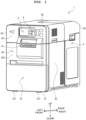
FIG. 1 is a perspective view of aprinter 1. -
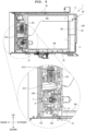
FIG. 2 is a vertical cross-sectional view depicting the internal configuration of theprinter 1. -
FIG. 3 is a front view of anaccommodating part 6. -
FIG. 4 is a perspective view depicting a state that acartridge 30 is being inserted into theaccommodating part 6. -
FIG. 5 is a vertical cross-sectional view depicting a state that thecartridge 30 is inserted into theaccommodating part 6. -
FIG. 6 is a perspective view of thecartridge 30. -
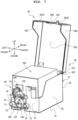
FIG. 7 is a perspective view depicting a state that aliquid container 100 is installed in thecartridge 30. -
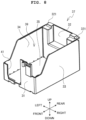
FIG. 8 is a perspective view of alower case 37. -
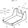
FIG. 9 is a perspective view of thecover 36 depicting a state that a lower side of thecover 36 is oriented upward. -
FIG. 10 is a front view of aliquid container 100. -
FIG. 11 is a perspective view of theliquid container 100. -
FIG. 12 is a right side view of thecartridge 30. -
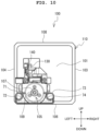
FIG. 13 is a front view of amaintenance box 300. - A
printer 1 according to an embodiment of the present invention will be explained, sequentially with reference to the drawings. In the present embodiment, a mechanical element in the drawings indicates an actual scale in each of the drawings. The drawings which are referred to are used for explaining a technical feature which may be adopted by the present invention, and the configuration of an apparatus which is described is not meant to be limited only thereto, and is a mere example for explanation. In the explanation of the present embodiment, a left lower side, a right upper side, a right lower side, a left upper side, an upper side and a lower side ofFIG. 1 are, respectively, a front side, a rear side, a right side, a left side, an upper side and a lower side of theprinter 1. A left lower side, a right upper side, a right lower side, a left upper side, an upper side and a lower side ofFIG. 6 are, respectively, a front side, a rear side, a right side, a left side, an upper side and a lower side of acartridge 30.FIGs. 1 to 5 are drawings with the directions of theprinter 1, whereasFIGs. 6 to 13 are drawings with the directions of thecartridge 30 or themaintenance box 300, and thecartridge 30 and the maintenance box 300are installed in theprinter 1 in a state that the front surfaces of thecartridge 30 and themaintenance box 300 are oriented to face the rear surface of theprinter 1. - The configuration of the
printer 1 will be explained, with reference toFIG. 1 . Theprinter 1 is an ink-jet printer which performs printing on a medium having an elongated shape. In a case that print data is inputted to an input terminal (omitted in the drawings), theprinter 1 prints the print data on the medium by a printing mechanism (omitted in the drawings) built in theprinter 1, and discharges the medium from a discharge port 21 (to be described later on). As depicted inFIG 1 , theprinter 1 is provided with acasing 2. Thecasing 2 has a shape of rectangular parallelepiped having a size placeable or arrangeable on a table or desk, and has afront wall 24, aright wall 25, arear wall 26, aleft wall 29, abottom wall 27, anupper wall 28 and afront cover 23. - The
front wall 24 is provided on a front surface of thecasing 2, and has, from the upper side toward the lower side, a firstfront wall 241 and a secondfront wall 242. Each of the firstfront wall 241 and the secondfront wall 242 is rectangular which is long in a left-right direction as seen from the front side. The firstfront wall 241 is provided on an upper part on the front side of thecasing 2, and thesecond front wall 242 is provided at a location which is below the firstfront wall 241 and which is at the center on the front side of thecasing 2. Each of theright wall 25, therear wall 26 and theleft wall 29 is rectangular which is long in an up-down direction. Further, each of thebottom wall 27 and theupper wall 28 is rectangular which is long in a front-rear direction. - The
discharge port 21 is provided on a boundary between the firstfront wall 241 and the secondfront wall 242. Thedischarge port 21 is a rectangular opening which is long in the left-right direction as seen from the front side, and discharges a medium having printing performed thereon. The firstfront wall 241 is provided with a displayingpart 3 and anoperating part 4. The displayingpart 3 displays a letter, an image, etc. Theoperating part 4 is provided on the right side with respect to the displayingpart 3. The operatingpart 4 is provided with a touch panel or a plurality of buttons via which a variety of kinds of instructions are inputted. - The
front cover 23 is provided on the front surface of thecasing 2 and below the secondfront wall 242. Thefront cover 23 is a rectangular lid as seen from the front side, and is provided with a pair ofhinges 231 on a lower end part of thefront cover 23. By the pair ofhinges 231, thefront cover 23 is rotatable to a close position (seeFIG. 1 ) at which thefront cover 23 closes anopening part 11 and anopening part 12 of anaccommodating part 6, depicted inFIG. 3 , and to an open position at which thefront cover 23 releases (does not cover) theopening part 11 and theopening part 12. - As depicted in
FIG. 2 , theprinter 1 accommodates, in the inside of thecasing 2, an ink-jet head 8, acartridge 30, anink tube 48, a conveyingdevice 45, apartition wall 55 and afixing unit 143. - The ink-
jet head 8 prints an image on a medium M supplied from a supplyingpart 5. The ink-jet head 8 is provided with a plurality ofnozzles 70 which discharges or ejects an ink G in a discharge direction. The ink-jet head 8 prints the image on the medium M by discharging the ink G from the plurality ofnozzles 70. The discharge direction is downward, and the ink-jet head 8 is provided at a location above a conveying route Q of the medium M, while theinkjet head 8 assumes a posture in which the plurality ofnozzles 70 is oriented downward. The conveying route Q is a route or path along which the medium M is conveyed since the medium M is fed out from the supplyingpart 5 and until the medium M is discharged from thedischarge port 21 to the outside of thecasing 2. - The
cartridge 30 is accommodated in theopening part 11. Thecartridge 30 accommodates aliquid container 100 which stores the ink in the inside thereof, and is installed in aninstallment part 7 of theopening part 11. The details of thecartridge 30 will be described later on. Theink tube 48 is arranged in the inside of thecasing 2 and connects theinstallment part 7 and the ink-jet head 8. The ink G in the inside of thecartridge 30 is supplied, via theink tube 48, from thecartridge 30 to the ink-jet head 8. - The conveying
device 45 is provided with the supplyingpart 5, conveyingparts part 80, atension applying part 60 and arotary body 75. The supplyingpart 5 is provided on a space which is located on the left side of thefront cover 23 at the close position and which is located at a rear lower part of theprinter 1 and surrounded by thepartition wall 55 and therear wall 26. The supplyingpart 5 holds a roll R. The supplyingpart 5 is provided with a shaft part 51 and amagazine 52. The shaft part 51 extends in the left-right direction, and is inserted into a paper tube K of the roll R. Themagazine 52 is a supporting stand which has a shape of a letter "U" as seen from the front side. Themagazine 52 supports both of left and right end parts of the shaft part 51 so that the shaft part 51 is rotatable about an axis extending in the left-right direction. The shaft part 51 is supported by themagazine 52 in a state that the shaft part 51 is detachable from themagazine 52. Themagazine 52 is supported by theprinter 1 in a state that themagazine 52 is detachable from theprinter 1. - An operator who replaces the roll R arranges the
front cover 23 at the open position, takes out themagazine 52 from the inside of thecasing 2 and performs a replacing operation of the roll R. - The conveying
part 270 conveys the medium M in a conveying direction F in which the medium M is conveyed from the supplyingpart 5 toward the ink-jet head 8 and to a retuning direction B which is opposite or reverse direction to the conveying direction F. The conveying direction F is a direction along the conveying route Q which is from the supplyingpart 5 toward the ink-jet head 8. A part, of the conveying direction F, from the supplingpart 5 up to thetension applying part 60 is a direction which changes depending on a remaining amount of the medium M, and is generally upward. A part, of the conveying direction F, from thetension applying part 60 up to thedischarge port 21 is generally frontward. - The conveying
part 270 is provided at a location on an upstream side in the conveying direction F with respect to the ink-jet head 8, and on a downstream side in the conveying direction F with respect to the supplyingpart 5. That is, the conveyingpart 270 is provided between the ink-jet head 8 and the supplyingpart 5 in the conveying route Q of the medium M.The conveying part 270 has a conveyingroller 271 which rotates about an axis extending in the left-right direction and apinch roller 272 which rotates about an axis extending in the left-right direction. The conveyingpart 270 performs a nip conveyance, by the conveyingroller 271 and thepinch roller 272, of conveying the medium M in the conveying direction F which is from the supplyingpart 5 toward the ink-jet head 8. - The conveying
part 10 is provided on the upstream side in the conveying direction F with respect to the conveyingpart 270, and conveys the medium in the conveying direction F and the retuning direction B. The conveyingpart 10 rotates the roll R held by the supplyingpart 5, conveys the medium M in the returning direction B, and takes (winds) the medium M on the roll R. The conveyingpart 10 detachably engages with the shaft part 51 of the supplyingpart 5. The conveyingpart 10 rotates the roll R held by the supplyingpart 5, conveys the medium M in the conveying direction F, and feeds the medium M from the roll R toward the ink-jet head 8. - The supporting
part 80 is provided on the upstream side in the conveying direction F with respect to the conveyingpart 270 and on the downstream side in the conveying direction F with respect to the conveyingpart 10, and supports thetension applying part 60 and therotary body 75. Thetension applying part 60 is provided between the conveyingpart 270 and the conveyingpart 10 in the conveying route Q. Thetension applying part 60 is arranged at a location above the supplyingpart 5, and is supported in a state that thetension applying part 60 is capable of rocking about an axis extending in the left-right direction, on the upstream side in the conveying direction F with respect to the conveyingpart 270. Thetension applying part 60 makes contact with the medium M and bends the medium M. With this, thetension applying part 60 imparts a tension to the medium M. The tension is a tension acting in a direction opposite to an advancing direction of the medium M. - The
rotary body 75 is supported to be rotatable about an axis extending in the left-right direction, on the upstream side in the conveying direction F with respect to the conveyingpart 270 and on the downstream side in the conveying direction F with respect to at an end part, of thetension applying part 60, on the upstream side in the conveying direction F, namely a lower end part of thetension applying part 60. - The conveying
part 15 is provided on a location below the ink-jet head 8 and on the downstream side in the conveying direction F with respect to the conveyingpart 270, and conveys the medium M in the conveying direction F.The conveying part 15 is provided with a drivingroller 113, a drivenroller 14 and anendless belt 16. The drivingroller 113 and the drivenroller 14 are separated from each other in the front-rear direction. Theendless belt 16 is stretched over the drivingroller 113 and the drivenroller 14. Accompanying with the rotation of theendless belt 16, the drivenroller 14 is rotated. A position in the up-down direction of an upper end of an outer circumferential surface of theendless belt 16 is substantially same with a position in the up-down direction of anip point 89 at which the medium M is nipped by the conveyingpart 270. The upper end of the outer circumferential surface of theendless belt 16 faces or is opposed to the plurality ofnozzles 70 of the ink-jet head 8. The upper end of the outer circumferential surface of theendless belt 16 conveys the medium M in a state that the medium M which is (being) conveyed between the conveyingpart 270 and the conveyingpart 19 is attracted, by suction from a position below the medium M by a static electricity or a negative pressure, to theendless belt 16. - The fixing
unit 143 is arranged on the downstream side in the conveying direction F with respect to the ink-jet head 8 and on the upstream side in the conveying direction F with respect to the conveyingpart 19. Further, the fixingunit 143 is provided on a location below the conveying route Q. The fixingunit 143 is provided with aheat source 144 which is capable of performing conduction heating and a heating plate (hot plate) 142 which is heated by theheat source 144. Theheating plate 142 supports the medium M which passes the conveying route Q from a position below the medium M. The medium M is heated by theheating plate 142, thereby causing the ink G discharged onto the medium M by the ink-jet head 8 to be fixed on the medium M. - The conveying
part 19 is provided on the downstream side in the conveying direction F with respect to the ink-jet head 8 and the fixingunit 143 and on the upstream side in the conveying direction F with respect to thedischarge port 21, and conveys the medium M in the conveying direction F and in the returning direction B. The conveyingpart 19 has a conveyingroller 17 and apinch roller 18 each of which rotates about an axis extending in the left-right direction, and performs a nip conveyance, by the conveyingroller 17 and thepinch roller 18, of conveying the medium M while nipping the medium M between the conveyingroller 17 and thepinch roller 18 in the up-down direction. - In a case that a printing processing is executed, a controller of the
printer 1 drives the conveyingparts printer 1 adjusts a driving amount of each of the conveyingparts tension applying part 60. The controller of theprinter 1 drives the ink-jet head 8 synchronizing with the conveyance of the medium M, thereby discharging, onto the medium M, the ink G supplied from thecartridge 30 via theink tube 48. The controller of theprinter 1 drives theheat source 144 so as to fix, to the medium M, the ink G on the medium M. The medium M is discharged from thedischarge port 21 to the outside of thecasing 2. - With reference to
FIGs. 3 to 5 , an explanation will be given about the configuration of theaccommodating part 6 provided on the inside of theprinter 1.FIGs. 3 and4 depict only theaccommodating part 6, and omits other configurations of theprinter 1. Theaccommodating part 6 is provided on the inside of thefront cover 23 of theprinter 1. Theaccommodating part 6 has a shape of a rectangular parallelepiped which extends in the left-right direction, and is provided with, from the left side toward the right side, a firstaccommodating part 61 and a secondaccommodating part 62. The firstaccommodating part 61 and the secondaccommodating part 62 are each a space having a shape of a rectangular parallelepiped, and provided, respectively, with anopening part 11 and anopening part 12 which are opened frontward. In a case that thefront cover 23 is changed from the close state to the open state, the openingparts accommodating part 6 are exposed. Each of the openingparts FIGs. 4 and5 , the firstaccommodating part 61 accommodates a cartridge 30 (to be described later on). - As depicted in
FIG. 6 , thecartridge 30 has a shape of a rectangular parallelepiped. As depicted inFIG. 7 , thecartridge 30 accommodates or stores theliquid container 100 which stores a liquid. Theliquid container 100 accommodates or stores an ink. Theliquid container 100 is a pouch made of a synthetic resin. In the following, an example that the ink is stored in theliquid container 100 will be explained. The details of the configuration of thecartridge 30 will be described later on. The secondaccommodating part 62 accommodates, for example, amaintenance box 300. - As depicted in
FIGs. 3 and5 , the firstaccommodating part 61 is provided with arear wall 610. Therear wall 610 is a rectangular wall which is provided on the rearmost side in the firstaccommodating part 61, and extends in the up-down direction and the left-right direction. Therear wall 610 is provided with theinstallment part 7. Theinstallment part 7 is provided on a location below a center in the up-down direction of therear wall 610. In a case that thecartridge 30 is accommodated in the firstaccommodating part 61, a tap (tap unit, mouth stopper, mouth plug) 105 of theliquid container 100 accommodated in thecartridge 30 is installed in theinstallment part 7. Theinstallment part 7 is provided with asupply needle 9 which projects frontward. Thesupply needle 9 is hollow inside. In a case that thecartridge 30 is accommodated in the firstaccommodating part 61 and that thetap 105 is installed in theinstallment part 7, thesupply needle 9 enters into the inside of asupply port 109 of a connectingpart 107 of theliquid container 100. Accordingly, the ink inside theliquid container 100 is supplied to the ink-jet head 8 of theprinter 1. - Further, a pair of positioning (alignment)
projections rear wall 610 of the firstaccommodating part 61. Thepositioning projection 611 and thepositioning projection 612 are provided, respectively, on positions which are symmetric in the left-right direction with respect to thesupply needle 9. Thepositioning projection 611 and thepositioning projection 612 project frontward. A front end of each of thepositioning projection 611 and thepositioning projection 612 protrudes frontward farther than a front end of thesupply needle 9. In a case that thecartridge 30 is inserted into the firstaccommodating part 61, thepositioning projection 612 fits into acircular hole 72 of a first positioning part 71 (to be described later on) and thepositioning projection 611 fits into anelongated hole 74 of a second positioning part 73 (to be described later on). - A
maintenance box 300 as depicted inFIG. 13 is accommodated in the secondaccommodating part 62. Themaintenance box 300 has a shape of a rectangular parallelepiped, similarly to thecartridge 30. Themaintenance box 300 is fixed in a state that themaintenance box 300 is accommodated in the secondaccommodating part 62. A storingbody 1000 storing a nozzle cleaning liquid for maintenance is accommodated in themaintenance box 300. The detailed configuration of themaintenance box 300 will be described later on. - Further, as depicted in
FIG. 3 , a pair of positioning (alignment)projections rear wall 620 of the secondaccommodating part 62. Thepositioning projection 711 and thepositioning projection 712 are provided, respectively, on positions which are symmetric in the left-right direction with respect to a cleaningliquid needle 90. Thepositioning projection 711 and thepositioning projection 712 project frontward. A front end of each of thepositioning projection 711 and thepositioning projection 712 protrudes frontward farther than a front end of the cleaningliquid needle 90. In a case that themaintenance box 300 is inserted into the secondaccommodating part 62, thepositioning projection 712 fits into acircular hole 82 of afirst positioning part 81 as depicted inFIG. 13 and thepositioning projection 711 fits into anelongated hole 84 of asecond positioning part 83. - With reference to
FIGs. 6 to 9 , the configuration of thecartridge 30 will be explained. As depicted inFIG. 6 , thecartridge 30 has a shape of a rectangular parallelepiped, and is provided with alower case 37 and acover 36. As depicted inFIG. 7 , thecartridge 30 accommodates or stores theliquid container 100 in the inside of thelower case 37, and thecover 36 is closed as depicted inFIG. 6 . - As depicted in
FIG. 8 , thelower case 37 is provided with afront wall 31, arear wall 32, aright wall 33, aleft wall 34 and abottom wall 35. Thebottom wall 35 is a rectangular plate which is long in the front-rear direction. Thefront wall 31 extends upward from a front end of thebottom wall 35. Atap engaging part 41 is provided on a left lower part of thefront wall 31. Thetap engaging part 41 is an opening part which penetrates thefront wall 31 in the front-rear direction and which is opened upwardly. As depicted inFIG. 7 , thetap 105 of theliquid container 100 engages with thetap engaging part 41 from a position above thetap engaging part 41. Thefront wall 31 supports thetap 105 of theliquid container 100. - As depicted in
FIG. 8 , theright wall 33 of thelower case 37 extends upward from a right end of thebottom wall 35. An upper part on the front side of theright wall 33 is inclined upward further toward the rear side. A length in the up-down direction of a front end part of theright wall 33 is substantially same as a length in the up-down direction of a right end part of thefront wall 31. Theleft wall 34 extends upward from a left end of thebottom wall 35. A length in the up-down direction of a front end part of theleft wall 34 is substantially same as a length in the up-down direction of a left end part of thefront wall 31. An upper part on the front side of theleft wall 34 is inclined upward further toward the rear side. A length in the up-down direction of a part on the rear side of theright wall 33 is approximately two times the length in the up-down direction of the front end part of theright wall 33, and a length in the up-down direction of a part on the rear side of theleft wall 34 is approximately two times the length in the up-down direction of the front end part of theleft wall 34. - The
rear wall 32 extends upward from a rear end of thebottom wall 35. A length in the up-down direction of therear wall 32 is approximately same as the length of the part on the rear side of each of theright wall 33 and theleft wall 34. A pair ofshafts 321 protrudes, in the left-right direction, respectively, on a left part and a right part of an upper end of therear wall 32. Anopening 39 which is opened upward is defined by thefront wall 31, theright wall 33, theleft wall 34 and therear wall 32. Theliquid container 100 is accommodated in the inside of theopening 39. -
FIG. 9 is a perspective view depicting thecover 36 in a state that a lower side of thecover 36 is oriented upward. As depicted inFIG. 9 , thecover 36 is provided with anupper wall 365, afront wall 361, arear wall 362, aright wall 364 and aleft wall 363. Theupper wall 365 is a rectangular plate which is long in the front-rear direction. Thefront wall 361 extends downwards from a front end part of theupper wall 365. Acutout part 361A and acutout part 361B are provided on thefront wall 361, and aside wall 366 extends downward between thecutout part 361A and thecutout part 361B. Therear wall 362 is a rectangular plate which extends downward from a rear end of theupper wall 365, and a pair of bearingparts 367 is provided, respectively, on both of left and right end parts of a lower end of therear wall 362. Theright wall 364 is a plate extending downward from a right end of theupper wall 365; a length in the up-down direction of a front side of theright wall 364 is longer than a length in the up-down direction of a rear side of theright wall 364; and theright wall 364 is provided with an inclined part which is inclined toward the front side from the rear side. Theleft wall 363 is a plate extending downward from a left end of theupper wall 365; a length in the up-down direction of a front side of theleft wall 363 is longer than a length in the up-down direction of a rear side of theleft wall 363; and theleft wall 363 is provided with an inclined part which is inclined toward the front side from the rear side. - The pair of bearing
parts 367 of thecover 36 is rotatably supported, respectively, by the pair ofshafts 321 of thelower case 37, thereby causing thecover 36 to rotate to a close state in which thecover 36 covers theopening 39 and to an open state in which thecover 36 does not cover theopening 39. In the open state depicted inFIG. 7 , the operator is capable of attaching and detaching theliquid container 100 with respect to thecartridge 30. In a case that thecover 36 is in the closed state, thecartridge 30 is accommodatable in theaccommodating part 6 of theprinter 1. - With reference to
FIGs. 10 and11 , the configuration of theliquid container 100 will be explained. Theliquid container 100 stores, as an example, an ink. An example of the ink, for example, is a black ink. Theliquid container 100 is provided with acase 110. Thecase 110 is formed of a pouch made of a synthetic resin. Thecase 110 has a shape of a rectangular parallelepiped which is long in the front-rear direction. Thecase 110 is provided with afront surface 101, arear surface 102, aright side surface 103, aleft side surface 104, abottom surface 106 and anupper surface 108. Thebottom surface 106 and theupper surface 108 are each a rectangle which is long in the front-rear direction. Thefront surface 101 is a rectangle which extends upward from a front end of thebottom surface 106. Theright side surface 103 is a rectangle which extends upward from a right end of thebottom surface 106 and which is long in the front-rear direction. Theleft side surface 104 is a rectangle which extends upward from a left end of thebottom surface 106 and which is long in the front-rear direction. Therear surface 102 is a rectangle which extends upward from a rear end of thebottom surface 106. - As depicted in
FIG. 10 , the tap 105 (tap unit) is provided on a left lower part of thefront surface 101. Thetap 105 is provided with a connectingpart 107, the first positioning (alignment)part 71, the second positioning (alignment)part 73 and acircuit board holder 130. The connectingpart 107 is a cylinder which extends, with respect to thefront surface 101, in a front direction which is orthogonal to thefront surface 101. The connectingpart 107 has thesupply port 109 opened in the front direction at a center of the connectingpart 107. Thesupply port 109 of the connectingpart 107 is a supply port via which the ink is supplied from theliquid container 100 to the outside of theliquid container 100. The connectingpart 107 extends from thefront surface 101 in an opening direction of thesupply port 109. Further, a sealing member (omitted in the drawings) is provided on a part which is located on the back side (on the rear side) of thesupply port 109. In a case, for example, that thecartridge 30 is detached from theinstallment part 7 and connection between thesupply port 109 of the connectingpart 107 and thesupply needle 9 is released, any leaking of the ink from thesupply port 109 is suppressed by the sealing member. - The
first positioning part 71 is provided on a position which is obliquely lower left with respect to thesupply port 109, in a crossing direction which crosses the opening direction (front direction) of thesupply port 109. Thecircular hole 72 of which opening is circular is provided on a front end part of thefirst positioning part 71. Thesecond positioning part 73 is provided on a position which is obliquely lower right with respect to thesupply port 109, in the crossing direction which crosses the opening direction (front direction) of thesupply port 109. Theelongated hole 74 of which opening is elongated in a lateral direction is provided on a front end part of thesecond positioning part 73. Theelongated hole 74 has a size in a long axis (major axis) direction of theelongated hole 74 which is from theelongated hole 74 toward thecircular hole 72, namely a size in the left-right direction, and a size in a short axis (minor axis) direction of theelongated hole 74 which is orthogonal to the long axis direction, namely a size in the up-down direction. The size of theelongated hole 74 in the long axis direction is larger than the size of theelongated hole 74 in the short axis direction. An example of the elongated hole is a hole of which opening is an oval or an ellipse. - Further, the
first positioning part 71 extends, from thefront surface 101, in the opening direction of thesupply port 109. Furthermore, thesecond positioning part 73 extends, from thefront surface 101, in the opening direction of thesupply port 109. As depicted inFIGs. 11 and12 , each of thefirst positioning part 71 and thesecond positioning part 73 is longer in the opening direction (front direction) of thesupply port 109 than the connectingpart 107. That is, a length L1, from thefront surface 101, of each of thefirst positioning part 71 and thesecond positioning part 73 in the front-rear direction is longer than a length L2, from thefront surface 101, of the connectingpart 107 in the front-rear direction. As depicted inFIG. 10 , thefirst positioning part 71 and thesecond positioning part 73 are provided, respectively, positions which are symmetric in the left-right direction with respect to thesupply port 109. Further, thesupply port 109, thefirst positioning part 71 and thesecond positioning part 73 are provided on positions, respectively, facing thesupply needle 9, thepositioning projection 612 and thepositioning projection 611 in a case that thecartridge 30 is inserted into the firstaccommodating part 61. - As depicted in
FIGs. 10 and11 , thetap 105 is provided with thecircuit board holder 130 at a location above thesupply port 109. That is, thecircuit board holder 130 is provided at a position of which height from thebottom surface 106 of theliquid container 100 is greater than a height of thesupply port 109 from thebottom surface 106. Thecircuit board holder 130 holds acircuit board 140 detachably. Thecircuit board 140 has an electronic circuit built therein, and theelectric contact 141 is exposed on thecircuit board 140. Thecircuit board 140 stores information regarding a remaining amount of the liquid stored in theliquid container 100. An example of thecircuit board 140 is an IC chip. Thecircuit boards 140 is held by thecircuit board holder 130 in a state that a surface, of thecircuit board 140, on which theelectric contact 141 is provided faces (is oriented) upward. That is, thecartridge 30 is provided with thecircuit board 140 having anelectric contact 141, at the position of which height from thebottom surface 106 is greater than the height of thesupply port 109 from thebottom surface 106. Note that theelectric contact 141 of thecircuit board 140 makes contact with a contacting part 613 (seeFIGs. 3 and5 ) provided on the firstaccommodating part 61. - Further, as depicted in
FIGs. 10 and11 , thecircuit board holder 130 is arranged, in thetap 105, above a location between thefirst positioning part 71 and thesecond positioning part 73. Accordingly, thecircuit board 140 is arranged above the location between thefirst positioning part 71 and thesecond positioning part 73. - In a case that the
cartridge 30 is to be installed in theprinter 1, a user opens thefront cover 23 of theprinter 1, and inserts thecartridge 30 into theprinter 1. Further, in a case that the ink becomes insufficient during usage of theprinter 1 and that an instruction of replacing thecartridge 30 is displayed on the displayingpart 3, the user opens thefront cover 23 of theprinter 1 and replaces thecartridge 30. In these cases, since thecartridge 30 is provided with thefirst positioning part 71 which is provided on one side (first side) with respect to thesupply port 109 in the crossing direction crossing the opening direction of thesupply port 109, and thesecond positioning part 73 which is provided on the other side (second side) different from the one side with respect to thesupply port 109 in the crossing direction, the position of thesupply port 109 is positioned (aligned) with respect to thesupply needle 9 by thefirst positioning part 71 and thesecond positioning part 73. Accordingly, it is possible to lower any possibility that the position of thesupply port 109 might be deviated with respect to thesupply needle 9, to lower any connection failure of thesupply port 109, and to lower any possibility that the liquid might leak from thesupply port 109. - Further, since each of the
first positioning part 71 and thesecond positioning part 73 is longer in the opening direction of the supply port 109 (front direction) than the connectingpart 107, thepositioning projection 612 and thepositioning projection 611 of the firstaccommodating part 61 are inserted, respectively, into thefirst positioning part 71 and thesecond positioning part 73, before thesupply needle 9 is inserted into thesupply port 109. Accordingly, thesupply needle 9 is inserted correctly into thesupply port 109. - Furthermore, as depicted in
FIG. 10 , since thefirst positioning part 71 and thesecond positioning part 73 are provided, respectively, on the positions which are symmetric in the left-right direction with respect to thesupply port 109, the precision of positioning thesupply port 109 in the left-right direction is improved. - Moreover, since the
circular hole 72 of which opening is circular is provided on the front end part of thefirst positioning part 71, thepositioning projection 612 is inserted into thecircular hole 72 of thefirst positioning part 71 and the position (positioning) is determined precisely. Further, theelongated hole 74 of the front end part of thesecond positioning part 73 has the size in the long axis direction from thesecond positioning part 73 toward the circular hole 72 (or the supply port 109) is greater than the size of theelongated hole 74 in the short axis direction orthogonal to the major axis direction. Accordingly, even in a case that thepositioning projection 611 which is inserted into theelongated hole 74 is shifted in the major axis direction of theelongated hole 74, such a possibility that thepositioning projection 611 might not be inserted into theelongated hole 74 is lowered. - Furthermore, since the
circuit board 140 is provided at the position having the height from thebottom surface 106 of theliquid container 100 which is greater than the height of thesupply port 109 from thebottom surface 106, such a possibility that the liquid scattered from thesupply port 109 might adhere to theelectric contact 141 of thecircuit board 140 is lowered. Accordingly, the reliability of the conduction of theelectric contact 141 of thecircuit board 140 is improved. - Moreover, since the surface, of the
circuit board 140, on which theelectric contact 141 is provided, is oriented upward, such a possibility that the liquid scattered from thesupply port 109 might adhere to theelectric contact 141 of thecircuit board 140 is lowered. Further, since thecircuit board 140 is arranged above the location between thefirst positioning part 71 and thesecond positioning part 73, the precision of positioning (alignment) thecircuit board 140 with respect to the contactingpart 613 provided on the firstaccommodating part 61 is improved. - The
printer 1 is configured such that thecartridge 30 configured as described above can be installed in theprinter 1. Accordingly, theprinter 1 is capable of lowering a possibility that the position of thesupply port 109 might be deviated with respect to thesupply needle 9, capable of lowering any connection failure of thesupply port 109, and capable of lowering such a possibility that the liquid might leak from thesupply port 109. - In the above-described embodiment, the
front surface 101 is an example of a "first surface" of the prevent invention. Thecartridge 30 is an example of a "liquid storing cartridge" of the present invention. - The present invention is not limited to or restricted by the above-described embodiment, and various changes or modifications may be made without departing from the gist or spirit of the present invention. The
liquid container 100 is not limited to being box-shaped. Although theliquid container 100 stores the ink, theliquid container 100 is not limited to this. For example, theliquid container 100 may store a liquid different from the ink. For example, theliquid container 100 may store a preservative liquid (storage liquid, shipping liquid) which is introduced to theink tube 48 connecting thecartridge 30 and the ink-jet head 8 for a purpose of suppressing any solidification of the ink inside theink tube 48, in a case that theprinter 1 is shipped or in a case that theprinter 1 is stored for a long period of time. In this case, it is allowable to adopt, as the preservative liquid, a liquid having such a property that the liquid is less likely to volatilize. Further, it is also allowable to omit thelower case 37 and thecover 36 of thecartridge 30, and to install theliquid container 100 directly in theprinter 1. - In the above-described embodiment, although the
first positioning part 71 and thesecond positioning part 73 of thecartridge 30 which stores the ink are described, the present invention is not limited to this. As described above, it is allowable to provide a positioning member on the maintenance box. For example, as depicted inFIG. 13 , themaintenance box 300 is provided with a cleaningliquid supply port 85, a first positioning (alignment)part 81, a second positioning (alignment)part 83, a wasteliquid inflow port 86, anatmosphere communication hole 87 and awaste liquid window 88. The secondaccommodating part 62 is provided with a cleaningliquid needle 90, a positioning (alignment)projection 711, a positioning (alignment)projection 712, awaste liquid needle 713, anatmosphere communicating needle 714 and awaste liquid sensor 715. - In a case that the
maintenance box 300 is installed in the secondaccommodating part 62, the cleaningliquid needle 90 is inserted into the cleaningliquid supply port 85. With this, a nozzle cleaning liquid stored in abag 1001 of thestoring body 1000 is supplied to the inside of theprinter 1, via the cleaningliquid needle 90. In the case that themaintenance box 300 is installed in the secondaccommodating part 62, thepositioning projection 711 and thepositioning projection 712 are inserted, respectively, into theelongated hole 84 of thesecond positioning part 83 and thecircular hole 82 of thefirst positioning part 81. With this, the positioning of themaintenance box 300 in the inside of theprinter 1 is performed. In the case that themaintenance box 300 is installed in the secondaccommodating part 62, thewaste liquid needle 713 is inserted into the wasteliquid inflow port 86. Thenozzles 70 of the ink-jet head 8 are cleaned (washed) by using the nozzle cleaning liquid, and a waste liquid generated by the cleaning is caused to flow, via thewaste liquid needle 713, into a space which is different from the storingbody 1000 in the inside of themaintenance box 300, so that the waste liquid is thereby collected by themaintenance box 300. In the case that themaintenance box 300 is installed in the secondaccommodating part 62, theatmosphere communicating needle 714 is inserted into theatmosphere communication hole 87. With this, a space inside themaintenance box 300 is atmospherically communicated with the outside. In a case that the waste liquid collected by themaintenance box 300 is accumulated, a liquid surface of the waste liquid is raised up to a position of thewaste liquid window 88. In this situation, since thewaste liquid window 88 has a translucency, it is possible to visually recognize the liquid surface of the waste liquid, via thewaste liquid window 88, from the outside. Further, in the case that themaintenance box 300 is installed in the secondaccommodating part 62, thewaste liquid window 88 is positioned between a light emitting part and a light receiving part of thewaste liquid sensor 715. Accordingly, it is possible to detect whether or not the waste liquid collected by themaintenance box 300 becomes full, via thewaste liquid window 88, by thewaste liquid sensor 715. - By the configuration wherein the
maintenance box 300 is provided with thefirst positioning part 81 and thesecond positioning part 83 and the secondaccommodating part 62 is provided with thepositioning projection 711 and thepositioning projection 712, it is possible to achieve an effect which is similar to that achieved by thecartridge 30 and the firstaccommodating part 61. - In the above-described embodiment, although the ink is, for example, the black ink, the ink is not limited to or restricted by this. For example, the ink may be an ink such as a cyan ink, a magenta ink, a yellow ink, a white ink or a clear ink, etc.
- In the above-described embodiment, although the
liquid container 100 has the shape of rectangular parallelepiped, theliquid container 100 is not limited to this. For example, the shape of theliquid container 100 may be a shape of another polyhedron, or may be cylindrical. Further, it is allowable that theliquid container 100 does not have a shape which is symmetrical in the front-rear direction - In the embodiment, although each of the
first positioning part 71 and thesecond positioning part 73 is arranged at the position below thesupply port 109, it is allowable to arrange each of thefirst positioning part 71 and thesecond positioning part 73 at a position above thesupply port 109. Alternatively, it is also allowable to arrange either one of thefirst positioning part 71 and thesecond positioning part 73 at a position above thesupply port 109, and to arrange the other one of thefirst positioning part 71 and thesecond positioning part 73 at a position below thesupply port 109. - In the above-described embodiment, although the tap 150 is provided on a position which is biased toward the
left side surface 104 in the left-right direction, the arrangement of thetap 105 is not limited to this. For example, thetap 105 may be provided on a position which is biased toward theright side surface 103. In such a case, theinstallment part 7 of the firstaccommodating part 61 may be provided on a position corresponding to the arrangement position of thetap 105. -
- 1
- printer
- 9
- supply needle
- 30
- cartridge
- 37
- lower case
- 71
- first positioning part
- 72
- circular hole
- 73
- second positioning part
- 74
- elongated hole
- 100
- liquid container
- 101
- front surface
- 106
- bottom surface
- 107
- connecting part
- 109
- supply port
- 110
- case
- 140
- circuit board
- 141
- electric contact
Claims (8)
- A liquid storing cartridge comprising:a liquid container configured to store a liquid;a supply port configured to supply the liquid from the liquid container to an outside of the liquid container;a first positioning part provided in a first side with respect to the supply port in a crossing direction crossing an opening direction of the supply port; anda second positioning part provided in a second side with respect to the supply port in the crossing direction, the second side being opposite side from the first side with respect to the supply port.
- The liquid storing cartridge according to claim 1, wherein:the liquid container includes a case having a first surface;the supply port, the first positioning part and the second positioning part are provided on the first surface;the supply port is provided in a connecting part extending from the first surface in the opening direction of the supply port;each of the first positioning part and the second positioning part extends from the first surface in the opening direction; andeach of the first positioning part and the second positioning part is longer than the connecting part in the opening direction.
- The liquid storing cartridge according to claim 1 or 2, wherein the first positioning part and the second positioning part are positioned symmetrically with respect to the supply port in a left-right direction.
- The liquid storing cartridge according to any one of claims 1 to 3, wherein:a circular hole is provided at an end of the first positioning part;an elongated hole is provided at an end of the second positioning part; andthe elongated hole has a size in a long axis direction from the elongated hole toward the circular hole and a size in a short axis direction orthogonal to the long axis direction, the size in the long axis direction being larger than the size in the short axis direction.
- The liquid storing cartridge according to any one of claims 1 to 4, wherein the liquid container is provided with a bottom surface, and
the liquid storing cartridge further comprises a circuit board having an electric contact, a height of the circuit board from the bottom surface is greater than a height of the supply port from the bottom surface. - The liquid storing cartridge according to claim 5, wherein a surface of the circuit board, on which the electric contact is provided, is oriented upward.
- The liquid storing cartridge according to claim 5 or 6, wherein the circuit board is arranged above a location between the first positioning part and the second positioning part.
- A printer comprising the liquid storing cartridge as defined in any one of claims 1 to 7.
Applications Claiming Priority (1)
| Application Number | Priority Date | Filing Date | Title |
|---|---|---|---|
| JP2022061282A JP2023151591A (en) | 2022-03-31 | 2022-03-31 | Liquid cartridges and printers |
Publications (2)
| Publication Number | Publication Date |
|---|---|
| EP4253063A1 true EP4253063A1 (en) | 2023-10-04 |
| EP4253063B1 EP4253063B1 (en) | 2024-11-13 |
Family
ID=85704625
Family Applications (1)
| Application Number | Title | Priority Date | Filing Date |
|---|---|---|---|
| EP23162766.2A Active EP4253063B1 (en) | 2022-03-31 | 2023-03-20 | Liquid storing cartridge and printer |
Country Status (3)
| Country | Link |
|---|---|
| US (1) | US12654457B2 (en) |
| EP (1) | EP4253063B1 (en) |
| JP (1) | JP2023151591A (en) |
Citations (3)
| Publication number | Priority date | Publication date | Assignee | Title |
|---|---|---|---|---|
| US7380909B2 (en) * | 2000-01-21 | 2008-06-03 | Seiko Epson Corporation | Ink cartridge for use with recording apparatus and ink jet recording apparatus |
| US20160031225A1 (en) * | 2014-08-01 | 2016-02-04 | Seiko Epson Corporation | Liquid supply system, liquid ejecting apparatus, and liquid supply method |
| JP2017065152A (en) | 2015-09-30 | 2017-04-06 | ブラザー工業株式会社 | Cartridge case |
Family Cites Families (9)
| Publication number | Priority date | Publication date | Assignee | Title |
|---|---|---|---|---|
| KR100361484B1 (en) * | 1997-08-28 | 2002-11-21 | 세이코 엡슨 가부시키가이샤 | Ink cartridge having waste ink absorbing function |
| JP2002019135A (en) * | 2000-07-04 | 2002-01-23 | Seiko Epson Corp | Ink cartridge for recording device and ink jet recording device |
| JP2005053212A (en) * | 2003-07-18 | 2005-03-03 | Seiko Epson Corp | Liquid container |
| JP4701959B2 (en) * | 2005-09-26 | 2011-06-15 | ソニー株式会社 | Liquid cartridge |
| RU2654423C2 (en) | 2013-09-18 | 2018-05-17 | Кэнон Кабусики Кайся | Ink cartridge and inkjet printer |
| JP6819077B2 (en) * | 2016-05-27 | 2021-01-27 | セイコーエプソン株式会社 | Liquid injection device |
| WO2017204072A1 (en) | 2016-05-27 | 2017-11-30 | セイコーエプソン株式会社 | Liquid-accommodating body, and liquid jet system |
| JP7388002B2 (en) * | 2019-05-29 | 2023-11-29 | セイコーエプソン株式会社 | Liquid container, mounting body, and liquid injection device |
| JP7459493B2 (en) * | 2019-12-05 | 2024-04-02 | セイコーエプソン株式会社 | Liquid ejection device |
-
2022
- 2022-03-31 JP JP2022061282A patent/JP2023151591A/en active Pending
-
2023
- 2023-03-20 EP EP23162766.2A patent/EP4253063B1/en active Active
- 2023-03-29 US US18/192,566 patent/US12654457B2/en active Active
Patent Citations (3)
| Publication number | Priority date | Publication date | Assignee | Title |
|---|---|---|---|---|
| US7380909B2 (en) * | 2000-01-21 | 2008-06-03 | Seiko Epson Corporation | Ink cartridge for use with recording apparatus and ink jet recording apparatus |
| US20160031225A1 (en) * | 2014-08-01 | 2016-02-04 | Seiko Epson Corporation | Liquid supply system, liquid ejecting apparatus, and liquid supply method |
| JP2017065152A (en) | 2015-09-30 | 2017-04-06 | ブラザー工業株式会社 | Cartridge case |
Also Published As
| Publication number | Publication date |
|---|---|
| US12654457B2 (en) | 2026-06-16 |
| EP4253063B1 (en) | 2024-11-13 |
| US20230311526A1 (en) | 2023-10-05 |
| JP2023151591A (en) | 2023-10-16 |
Similar Documents
| Publication | Publication Date | Title |
|---|---|---|
| CN103395293B (en) | Liquid delivery system and there is the liquid consuming device of this liquid delivery system | |
| JP6171313B2 (en) | Liquid ejector | |
| JP6696127B2 (en) | Printer | |
| JP7772139B2 (en) | liquid injection device | |
| CN103112251B (en) | Recording apparatus having liquid supply system | |
| CN102161263B (en) | Liquid ejecting system and liquid accommodating container | |
| CN103112250B (en) | With the recording equipment of recording medium conveyance mechanism | |
| JP2011167966A (en) | Liquid ejection system, liquid container and liquid ejector | |
| CN203077841U (en) | Adapter and liquid supply system | |
| CN104723689B (en) | Recording Apparatus | |
| JP2018187888A (en) | Liquid jet device | |
| CN112622447B (en) | Recording apparatus | |
| CN110641150A (en) | Recording apparatus | |
| CN203032093U (en) | Liquid supply system and liquid consumption device | |
| JP2017013242A (en) | Printing device | |
| EP4253063B1 (en) | Liquid storing cartridge and printer | |
| JP2013123846A (en) | Recording apparatus | |
| EP4253064A1 (en) | Liquid storing cartridge and printer | |
| JP2015077708A (en) | Liquid ejecting apparatus, adapter and liquid supply system | |
| US12570100B2 (en) | Liquid storing cartridge and printer | |
| CN203093317U (en) | Recording device | |
| US9862198B2 (en) | Unit used in liquid jet recording apparatus, and liquid jet recording apparatus | |
| US12325241B2 (en) | Pouch, cartridge, and printer | |
| JP6981142B2 (en) | Printing equipment | |
| JP6493474B2 (en) | Liquid ejecting apparatus and liquid supply system |
Legal Events
| Date | Code | Title | Description |
|---|---|---|---|
| PUAI | Public reference made under article 153(3) epc to a published international application that has entered the european phase |
Free format text: ORIGINAL CODE: 0009012 |
|
| STAA | Information on the status of an ep patent application or granted ep patent |
Free format text: STATUS: THE APPLICATION HAS BEEN PUBLISHED |
|
| AK | Designated contracting states |
Kind code of ref document: A1 Designated state(s): AL AT BE BG CH CY CZ DE DK EE ES FI FR GB GR HR HU IE IS IT LI LT LU LV MC ME MK MT NL NO PL PT RO RS SE SI SK SM TR |
|
| P01 | Opt-out of the competence of the unified patent court (upc) registered |
Effective date: 20231027 |
|
| STAA | Information on the status of an ep patent application or granted ep patent |
Free format text: STATUS: REQUEST FOR EXAMINATION WAS MADE |
|
| 17P | Request for examination filed |
Effective date: 20240403 |
|
| RBV | Designated contracting states (corrected) |
Designated state(s): AL AT BE BG CH CY CZ DE DK EE ES FI FR GB GR HR HU IE IS IT LI LT LU LV MC ME MK MT NL NO PL PT RO RS SE SI SK SM TR |
|
| RIC1 | Information provided on ipc code assigned before grant |
Ipc: B41J 29/13 20060101ALI20240516BHEP Ipc: B41J 29/02 20060101ALI20240516BHEP Ipc: B41J 2/175 20060101AFI20240516BHEP |
|
| GRAP | Despatch of communication of intention to grant a patent |
Free format text: ORIGINAL CODE: EPIDOSNIGR1 |
|
| STAA | Information on the status of an ep patent application or granted ep patent |
Free format text: STATUS: GRANT OF PATENT IS INTENDED |
|
| INTG | Intention to grant announced |
Effective date: 20240701 |
|
| GRAS | Grant fee paid |
Free format text: ORIGINAL CODE: EPIDOSNIGR3 |
|
| GRAA | (expected) grant |
Free format text: ORIGINAL CODE: 0009210 |
|
| STAA | Information on the status of an ep patent application or granted ep patent |
Free format text: STATUS: THE PATENT HAS BEEN GRANTED |
|
| AK | Designated contracting states |
Kind code of ref document: B1 Designated state(s): AL AT BE BG CH CY CZ DE DK EE ES FI FR GB GR HR HU IE IS IT LI LT LU LV MC ME MK MT NL NO PL PT RO RS SE SI SK SM TR |
|
| REG | Reference to a national code |
Ref country code: GB Ref legal event code: FG4D |
|
| REG | Reference to a national code |
Ref country code: CH Ref legal event code: EP |
|
| REG | Reference to a national code |
Ref country code: IE Ref legal event code: FG4D |
|
| REG | Reference to a national code |
Ref country code: DE Ref legal event code: R096 Ref document number: 602023000983 Country of ref document: DE |
|
| REG | Reference to a national code |
Ref country code: LT Ref legal event code: MG9D |
|
| REG | Reference to a national code |
Ref country code: NL Ref legal event code: MP Effective date: 20241113 |
|
| PG25 | Lapsed in a contracting state [announced via postgrant information from national office to epo] |
Ref country code: HR Free format text: LAPSE BECAUSE OF FAILURE TO SUBMIT A TRANSLATION OF THE DESCRIPTION OR TO PAY THE FEE WITHIN THE PRESCRIBED TIME-LIMIT Effective date: 20241113 Ref country code: PT Free format text: LAPSE BECAUSE OF FAILURE TO SUBMIT A TRANSLATION OF THE DESCRIPTION OR TO PAY THE FEE WITHIN THE PRESCRIBED TIME-LIMIT Effective date: 20250313 Ref country code: IS Free format text: LAPSE BECAUSE OF FAILURE TO SUBMIT A TRANSLATION OF THE DESCRIPTION OR TO PAY THE FEE WITHIN THE PRESCRIBED TIME-LIMIT Effective date: 20250313 |
|
| PG25 | Lapsed in a contracting state [announced via postgrant information from national office to epo] |
Ref country code: FI Free format text: LAPSE BECAUSE OF FAILURE TO SUBMIT A TRANSLATION OF THE DESCRIPTION OR TO PAY THE FEE WITHIN THE PRESCRIBED TIME-LIMIT Effective date: 20241113 Ref country code: NL Free format text: LAPSE BECAUSE OF FAILURE TO SUBMIT A TRANSLATION OF THE DESCRIPTION OR TO PAY THE FEE WITHIN THE PRESCRIBED TIME-LIMIT Effective date: 20241113 |
|
| REG | Reference to a national code |
Ref country code: AT Ref legal event code: MK05 Ref document number: 1741410 Country of ref document: AT Kind code of ref document: T Effective date: 20241113 |
|
| PG25 | Lapsed in a contracting state [announced via postgrant information from national office to epo] |
Ref country code: BG Free format text: LAPSE BECAUSE OF FAILURE TO SUBMIT A TRANSLATION OF THE DESCRIPTION OR TO PAY THE FEE WITHIN THE PRESCRIBED TIME-LIMIT Effective date: 20241113 |
|
| PG25 | Lapsed in a contracting state [announced via postgrant information from national office to epo] |
Ref country code: ES Free format text: LAPSE BECAUSE OF FAILURE TO SUBMIT A TRANSLATION OF THE DESCRIPTION OR TO PAY THE FEE WITHIN THE PRESCRIBED TIME-LIMIT Effective date: 20241113 |
|
| PG25 | Lapsed in a contracting state [announced via postgrant information from national office to epo] |
Ref country code: NO Free format text: LAPSE BECAUSE OF FAILURE TO SUBMIT A TRANSLATION OF THE DESCRIPTION OR TO PAY THE FEE WITHIN THE PRESCRIBED TIME-LIMIT Effective date: 20250213 |
|
| PG25 | Lapsed in a contracting state [announced via postgrant information from national office to epo] |
Ref country code: GR Free format text: LAPSE BECAUSE OF FAILURE TO SUBMIT A TRANSLATION OF THE DESCRIPTION OR TO PAY THE FEE WITHIN THE PRESCRIBED TIME-LIMIT Effective date: 20250214 Ref country code: LV Free format text: LAPSE BECAUSE OF FAILURE TO SUBMIT A TRANSLATION OF THE DESCRIPTION OR TO PAY THE FEE WITHIN THE PRESCRIBED TIME-LIMIT Effective date: 20241113 Ref country code: AT Free format text: LAPSE BECAUSE OF FAILURE TO SUBMIT A TRANSLATION OF THE DESCRIPTION OR TO PAY THE FEE WITHIN THE PRESCRIBED TIME-LIMIT Effective date: 20241113 |
|
| PG25 | Lapsed in a contracting state [announced via postgrant information from national office to epo] |
Ref country code: PL Free format text: LAPSE BECAUSE OF FAILURE TO SUBMIT A TRANSLATION OF THE DESCRIPTION OR TO PAY THE FEE WITHIN THE PRESCRIBED TIME-LIMIT Effective date: 20241113 |
|
| PG25 | Lapsed in a contracting state [announced via postgrant information from national office to epo] |
Ref country code: RS Free format text: LAPSE BECAUSE OF FAILURE TO SUBMIT A TRANSLATION OF THE DESCRIPTION OR TO PAY THE FEE WITHIN THE PRESCRIBED TIME-LIMIT Effective date: 20250213 |
|
| PG25 | Lapsed in a contracting state [announced via postgrant information from national office to epo] |
Ref country code: SM Free format text: LAPSE BECAUSE OF FAILURE TO SUBMIT A TRANSLATION OF THE DESCRIPTION OR TO PAY THE FEE WITHIN THE PRESCRIBED TIME-LIMIT Effective date: 20241113 |
|
| PG25 | Lapsed in a contracting state [announced via postgrant information from national office to epo] |
Ref country code: DK Free format text: LAPSE BECAUSE OF FAILURE TO SUBMIT A TRANSLATION OF THE DESCRIPTION OR TO PAY THE FEE WITHIN THE PRESCRIBED TIME-LIMIT Effective date: 20241113 |
|
| PG25 | Lapsed in a contracting state [announced via postgrant information from national office to epo] |
Ref country code: EE Free format text: LAPSE BECAUSE OF FAILURE TO SUBMIT A TRANSLATION OF THE DESCRIPTION OR TO PAY THE FEE WITHIN THE PRESCRIBED TIME-LIMIT Effective date: 20241113 |
|
| PG25 | Lapsed in a contracting state [announced via postgrant information from national office to epo] |
Ref country code: RO Free format text: LAPSE BECAUSE OF FAILURE TO SUBMIT A TRANSLATION OF THE DESCRIPTION OR TO PAY THE FEE WITHIN THE PRESCRIBED TIME-LIMIT Effective date: 20241113 |
|
| PG25 | Lapsed in a contracting state [announced via postgrant information from national office to epo] |
Ref country code: SK Free format text: LAPSE BECAUSE OF FAILURE TO SUBMIT A TRANSLATION OF THE DESCRIPTION OR TO PAY THE FEE WITHIN THE PRESCRIBED TIME-LIMIT Effective date: 20241113 |
|
| PG25 | Lapsed in a contracting state [announced via postgrant information from national office to epo] |
Ref country code: CZ Free format text: LAPSE BECAUSE OF FAILURE TO SUBMIT A TRANSLATION OF THE DESCRIPTION OR TO PAY THE FEE WITHIN THE PRESCRIBED TIME-LIMIT Effective date: 20241113 |
|
| PG25 | Lapsed in a contracting state [announced via postgrant information from national office to epo] |
Ref country code: IT Free format text: LAPSE BECAUSE OF FAILURE TO SUBMIT A TRANSLATION OF THE DESCRIPTION OR TO PAY THE FEE WITHIN THE PRESCRIBED TIME-LIMIT Effective date: 20241113 |
|
| REG | Reference to a national code |
Ref country code: DE Ref legal event code: R097 Ref document number: 602023000983 Country of ref document: DE |
|
| PG25 | Lapsed in a contracting state [announced via postgrant information from national office to epo] |
Ref country code: SE Free format text: LAPSE BECAUSE OF FAILURE TO SUBMIT A TRANSLATION OF THE DESCRIPTION OR TO PAY THE FEE WITHIN THE PRESCRIBED TIME-LIMIT Effective date: 20241113 |
|
| PLBE | No opposition filed within time limit |
Free format text: ORIGINAL CODE: 0009261 |
|
| STAA | Information on the status of an ep patent application or granted ep patent |
Free format text: STATUS: NO OPPOSITION FILED WITHIN TIME LIMIT |
|
| PG25 | Lapsed in a contracting state [announced via postgrant information from national office to epo] |
Ref country code: MC Free format text: LAPSE BECAUSE OF FAILURE TO SUBMIT A TRANSLATION OF THE DESCRIPTION OR TO PAY THE FEE WITHIN THE PRESCRIBED TIME-LIMIT Effective date: 20241113 |
|
| 26N | No opposition filed |
Effective date: 20250814 |
|
| PG25 | Lapsed in a contracting state [announced via postgrant information from national office to epo] |
Ref country code: LU Free format text: LAPSE BECAUSE OF NON-PAYMENT OF DUE FEES Effective date: 20250320 |
|
| REG | Reference to a national code |
Ref country code: BE Ref legal event code: MM Effective date: 20250331 |
|
| PG25 | Lapsed in a contracting state [announced via postgrant information from national office to epo] |
Ref country code: BE Free format text: LAPSE BECAUSE OF NON-PAYMENT OF DUE FEES Effective date: 20250331 |
|
| PG25 | Lapsed in a contracting state [announced via postgrant information from national office to epo] |
Ref country code: IE Free format text: LAPSE BECAUSE OF NON-PAYMENT OF DUE FEES Effective date: 20250320 |
|
| PGFP | Annual fee paid to national office [announced via postgrant information from national office to epo] |
Ref country code: DE Payment date: 20260213 Year of fee payment: 4 |
|
| PGFP | Annual fee paid to national office [announced via postgrant information from national office to epo] |
Ref country code: FR Payment date: 20260209 Year of fee payment: 4 |
|
| PG25 | Lapsed in a contracting state [announced via postgrant information from national office to epo] |
Ref country code: CY Free format text: LAPSE BECAUSE OF FAILURE TO SUBMIT A TRANSLATION OF THE DESCRIPTION OR TO PAY THE FEE WITHIN THE PRESCRIBED TIME-LIMIT Effective date: 20241113 |
|
| PG25 | Lapsed in a contracting state [announced via postgrant information from national office to epo] |
Ref country code: LT Free format text: LAPSE BECAUSE OF FAILURE TO SUBMIT A TRANSLATION OF THE DESCRIPTION OR TO PAY THE FEE WITHIN THE PRESCRIBED TIME-LIMIT Effective date: 20241113 |
|
| PG25 | Lapsed in a contracting state [announced via postgrant information from national office to epo] |
Ref country code: TR Free format text: LAPSE BECAUSE OF FAILURE TO SUBMIT A TRANSLATION OF THE DESCRIPTION OR TO PAY THE FEE WITHIN THE PRESCRIBED TIME-LIMIT Effective date: 20241113 |