EP4253042A1 - Multi-layer structure - Google Patents
Multi-layer structure Download PDFInfo
- Publication number
- EP4253042A1 EP4253042A1 EP21897628.0A EP21897628A EP4253042A1 EP 4253042 A1 EP4253042 A1 EP 4253042A1 EP 21897628 A EP21897628 A EP 21897628A EP 4253042 A1 EP4253042 A1 EP 4253042A1
- Authority
- EP
- European Patent Office
- Prior art keywords
- layer
- glass
- support
- tackifier
- resin
- Prior art date
- Legal status (The legal status is an assumption and is not a legal conclusion. Google has not performed a legal analysis and makes no representation as to the accuracy of the status listed.)
- Withdrawn
Links
- 239000011521 glass Substances 0.000 claims abstract description 90
- 229920005989 resin Polymers 0.000 claims abstract description 69
- 239000011347 resin Substances 0.000 claims abstract description 69
- 239000000463 material Substances 0.000 claims description 41
- 229910052751 metal Inorganic materials 0.000 claims description 19
- 239000002184 metal Substances 0.000 claims description 19
- NIXOWILDQLNWCW-UHFFFAOYSA-N acrylic acid group Chemical group C(C=C)(=O)O NIXOWILDQLNWCW-UHFFFAOYSA-N 0.000 claims description 12
- 229920000515 polycarbonate Polymers 0.000 claims description 3
- 239000004417 polycarbonate Substances 0.000 claims description 3
- 239000010410 layer Substances 0.000 description 195
- 239000012790 adhesive layer Substances 0.000 description 13
- 230000001070 adhesive effect Effects 0.000 description 11
- 238000000034 method Methods 0.000 description 11
- 239000000853 adhesive Substances 0.000 description 10
- 230000000052 comparative effect Effects 0.000 description 6
- VYPSYNLAJGMNEJ-UHFFFAOYSA-N Silicium dioxide Chemical compound O=[Si]=O VYPSYNLAJGMNEJ-UHFFFAOYSA-N 0.000 description 3
- 229920001187 thermosetting polymer Polymers 0.000 description 3
- 239000004593 Epoxy Substances 0.000 description 2
- KRHYYFGTRYWZRS-UHFFFAOYSA-N Fluorane Chemical compound F KRHYYFGTRYWZRS-UHFFFAOYSA-N 0.000 description 2
- 239000004642 Polyimide Substances 0.000 description 2
- BQCADISMDOOEFD-UHFFFAOYSA-N Silver Chemical compound [Ag] BQCADISMDOOEFD-UHFFFAOYSA-N 0.000 description 2
- 239000003513 alkali Substances 0.000 description 2
- 238000010586 diagram Methods 0.000 description 2
- 238000003280 down draw process Methods 0.000 description 2
- 230000000694 effects Effects 0.000 description 2
- 239000005357 flat glass Substances 0.000 description 2
- 239000011229 interlayer Substances 0.000 description 2
- 238000002844 melting Methods 0.000 description 2
- 230000008018 melting Effects 0.000 description 2
- 150000002739 metals Chemical class 0.000 description 2
- 238000007747 plating Methods 0.000 description 2
- 229920002037 poly(vinyl butyral) polymer Polymers 0.000 description 2
- -1 polyethylene terephthalate Polymers 0.000 description 2
- 229920001721 polyimide Polymers 0.000 description 2
- 229920001296 polysiloxane Polymers 0.000 description 2
- 229910052709 silver Inorganic materials 0.000 description 2
- 239000004332 silver Substances 0.000 description 2
- 238000004544 sputter deposition Methods 0.000 description 2
- 239000000126 substance Substances 0.000 description 2
- 238000002834 transmittance Methods 0.000 description 2
- 238000007740 vapor deposition Methods 0.000 description 2
- 229910001316 Ag alloy Inorganic materials 0.000 description 1
- OKTJSMMVPCPJKN-UHFFFAOYSA-N Carbon Chemical compound [C] OKTJSMMVPCPJKN-UHFFFAOYSA-N 0.000 description 1
- JOYRKODLDBILNP-UHFFFAOYSA-N Ethyl urethane Chemical compound CCOC(N)=O JOYRKODLDBILNP-UHFFFAOYSA-N 0.000 description 1
- FUJCRWPEOMXPAD-UHFFFAOYSA-N Li2O Inorganic materials [Li+].[Li+].[O-2] FUJCRWPEOMXPAD-UHFFFAOYSA-N 0.000 description 1
- 229920000877 Melamine resin Polymers 0.000 description 1
- KKCBUQHMOMHUOY-UHFFFAOYSA-N Na2O Inorganic materials [O-2].[Na+].[Na+] KKCBUQHMOMHUOY-UHFFFAOYSA-N 0.000 description 1
- ISWSIDIOOBJBQZ-UHFFFAOYSA-N Phenol Chemical compound OC1=CC=CC=C1 ISWSIDIOOBJBQZ-UHFFFAOYSA-N 0.000 description 1
- 238000006124 Pilkington process Methods 0.000 description 1
- 239000004695 Polyether sulfone Substances 0.000 description 1
- 239000004697 Polyetherimide Substances 0.000 description 1
- PMZURENOXWZQFD-UHFFFAOYSA-L Sodium Sulfate Chemical compound [Na+].[Na+].[O-]S([O-])(=O)=O PMZURENOXWZQFD-UHFFFAOYSA-L 0.000 description 1
- 229910052783 alkali metal Inorganic materials 0.000 description 1
- 150000001340 alkali metals Chemical class 0.000 description 1
- 229910052782 aluminium Inorganic materials 0.000 description 1
- XAGFODPZIPBFFR-UHFFFAOYSA-N aluminium Chemical compound [Al] XAGFODPZIPBFFR-UHFFFAOYSA-N 0.000 description 1
- PNEYBMLMFCGWSK-UHFFFAOYSA-N aluminium oxide Inorganic materials [O-2].[O-2].[O-2].[Al+3].[Al+3] PNEYBMLMFCGWSK-UHFFFAOYSA-N 0.000 description 1
- 239000005354 aluminosilicate glass Substances 0.000 description 1
- 150000001408 amides Chemical class 0.000 description 1
- 229910000410 antimony oxide Inorganic materials 0.000 description 1
- 230000006399 behavior Effects 0.000 description 1
- 230000015572 biosynthetic process Effects 0.000 description 1
- 239000005385 borate glass Substances 0.000 description 1
- QHIWVLPBUQWDMQ-UHFFFAOYSA-N butyl prop-2-enoate;methyl 2-methylprop-2-enoate;prop-2-enoic acid Chemical compound OC(=O)C=C.COC(=O)C(C)=C.CCCCOC(=O)C=C QHIWVLPBUQWDMQ-UHFFFAOYSA-N 0.000 description 1
- 229910052799 carbon Inorganic materials 0.000 description 1
- 229920002678 cellulose Polymers 0.000 description 1
- 239000001913 cellulose Substances 0.000 description 1
- 239000003638 chemical reducing agent Substances 0.000 description 1
- 238000001816 cooling Methods 0.000 description 1
- 230000007797 corrosion Effects 0.000 description 1
- 238000005260 corrosion Methods 0.000 description 1
- 150000001925 cycloalkenes Chemical class 0.000 description 1
- 239000013530 defoamer Substances 0.000 description 1
- XUCJHNOBJLKZNU-UHFFFAOYSA-M dilithium;hydroxide Chemical compound [Li+].[Li+].[OH-] XUCJHNOBJLKZNU-UHFFFAOYSA-M 0.000 description 1
- 239000005038 ethylene vinyl acetate Substances 0.000 description 1
- 230000002401 inhibitory effect Effects 0.000 description 1
- 239000002346 layers by function Substances 0.000 description 1
- 239000003562 lightweight material Substances 0.000 description 1
- JDSHMPZPIAZGSV-UHFFFAOYSA-N melamine Chemical compound NC1=NC(N)=NC(N)=N1 JDSHMPZPIAZGSV-UHFFFAOYSA-N 0.000 description 1
- 239000010446 mirabilite Substances 0.000 description 1
- 239000000203 mixture Substances 0.000 description 1
- 238000012986 modification Methods 0.000 description 1
- 230000004048 modification Effects 0.000 description 1
- JFNLZVQOOSMTJK-KNVOCYPGSA-N norbornene Chemical compound C1[C@@H]2CC[C@H]1C=C2 JFNLZVQOOSMTJK-KNVOCYPGSA-N 0.000 description 1
- 238000007500 overflow downdraw method Methods 0.000 description 1
- VTRUBDSFZJNXHI-UHFFFAOYSA-N oxoantimony Chemical compound [Sb]=O VTRUBDSFZJNXHI-UHFFFAOYSA-N 0.000 description 1
- 229920003207 poly(ethylene-2,6-naphthalate) Polymers 0.000 description 1
- 229920002492 poly(sulfone) Polymers 0.000 description 1
- 229920002647 polyamide Polymers 0.000 description 1
- 229920001230 polyarylate Polymers 0.000 description 1
- 229920001225 polyester resin Polymers 0.000 description 1
- 229920006393 polyether sulfone Polymers 0.000 description 1
- 229920001601 polyetherimide Polymers 0.000 description 1
- 239000011112 polyethylene naphthalate Substances 0.000 description 1
- 229920000139 polyethylene terephthalate Polymers 0.000 description 1
- 239000005020 polyethylene terephthalate Substances 0.000 description 1
- 229920005672 polyolefin resin Polymers 0.000 description 1
- NOTVAPJNGZMVSD-UHFFFAOYSA-N potassium monoxide Inorganic materials [K]O[K] NOTVAPJNGZMVSD-UHFFFAOYSA-N 0.000 description 1
- 230000002787 reinforcement Effects 0.000 description 1
- 239000000377 silicon dioxide Substances 0.000 description 1
- 239000005361 soda-lime glass Substances 0.000 description 1
- 239000002904 solvent Substances 0.000 description 1
Images

Classifications
-
- B—PERFORMING OPERATIONS; TRANSPORTING
- B32—LAYERED PRODUCTS
- B32B—LAYERED PRODUCTS, i.e. PRODUCTS BUILT-UP OF STRATA OF FLAT OR NON-FLAT, e.g. CELLULAR OR HONEYCOMB, FORM
- B32B17/00—Layered products essentially comprising sheet glass, or glass, slag, or like fibres
- B32B17/06—Layered products essentially comprising sheet glass, or glass, slag, or like fibres comprising glass as the main or only constituent of a layer, next to another layer of a specific material
- B32B17/10—Layered products essentially comprising sheet glass, or glass, slag, or like fibres comprising glass as the main or only constituent of a layer, next to another layer of a specific material of synthetic resin
- B32B17/10005—Layered products essentially comprising sheet glass, or glass, slag, or like fibres comprising glass as the main or only constituent of a layer, next to another layer of a specific material of synthetic resin laminated safety glass or glazing
- B32B17/10165—Functional features of the laminated safety glass or glazing
- B32B17/10174—Coatings of a metallic or dielectric material on a constituent layer of glass or polymer
- B32B17/1022—Metallic coatings
-
- B—PERFORMING OPERATIONS; TRANSPORTING
- B32—LAYERED PRODUCTS
- B32B—LAYERED PRODUCTS, i.e. PRODUCTS BUILT-UP OF STRATA OF FLAT OR NON-FLAT, e.g. CELLULAR OR HONEYCOMB, FORM
- B32B27/00—Layered products comprising a layer of synthetic resin
- B32B27/06—Layered products comprising a layer of synthetic resin as the main or only constituent of a layer, which is next to another layer of the same or of a different material
-
- B—PERFORMING OPERATIONS; TRANSPORTING
- B32—LAYERED PRODUCTS
- B32B—LAYERED PRODUCTS, i.e. PRODUCTS BUILT-UP OF STRATA OF FLAT OR NON-FLAT, e.g. CELLULAR OR HONEYCOMB, FORM
- B32B15/00—Layered products comprising a layer of metal
- B32B15/04—Layered products comprising a layer of metal comprising metal as the main or only constituent of a layer, which is next to another layer of the same or of a different material
- B32B15/08—Layered products comprising a layer of metal comprising metal as the main or only constituent of a layer, which is next to another layer of the same or of a different material of synthetic resin
- B32B15/082—Layered products comprising a layer of metal comprising metal as the main or only constituent of a layer, which is next to another layer of the same or of a different material of synthetic resin comprising vinyl resins; comprising acrylic resins
-
- B—PERFORMING OPERATIONS; TRANSPORTING
- B32—LAYERED PRODUCTS
- B32B—LAYERED PRODUCTS, i.e. PRODUCTS BUILT-UP OF STRATA OF FLAT OR NON-FLAT, e.g. CELLULAR OR HONEYCOMB, FORM
- B32B17/00—Layered products essentially comprising sheet glass, or glass, slag, or like fibres
- B32B17/06—Layered products essentially comprising sheet glass, or glass, slag, or like fibres comprising glass as the main or only constituent of a layer, next to another layer of a specific material
- B32B17/061—Layered products essentially comprising sheet glass, or glass, slag, or like fibres comprising glass as the main or only constituent of a layer, next to another layer of a specific material of metal
-
- B—PERFORMING OPERATIONS; TRANSPORTING
- B32—LAYERED PRODUCTS
- B32B—LAYERED PRODUCTS, i.e. PRODUCTS BUILT-UP OF STRATA OF FLAT OR NON-FLAT, e.g. CELLULAR OR HONEYCOMB, FORM
- B32B17/00—Layered products essentially comprising sheet glass, or glass, slag, or like fibres
- B32B17/06—Layered products essentially comprising sheet glass, or glass, slag, or like fibres comprising glass as the main or only constituent of a layer, next to another layer of a specific material
- B32B17/10—Layered products essentially comprising sheet glass, or glass, slag, or like fibres comprising glass as the main or only constituent of a layer, next to another layer of a specific material of synthetic resin
-
- B—PERFORMING OPERATIONS; TRANSPORTING
- B32—LAYERED PRODUCTS
- B32B—LAYERED PRODUCTS, i.e. PRODUCTS BUILT-UP OF STRATA OF FLAT OR NON-FLAT, e.g. CELLULAR OR HONEYCOMB, FORM
- B32B17/00—Layered products essentially comprising sheet glass, or glass, slag, or like fibres
- B32B17/06—Layered products essentially comprising sheet glass, or glass, slag, or like fibres comprising glass as the main or only constituent of a layer, next to another layer of a specific material
- B32B17/10—Layered products essentially comprising sheet glass, or glass, slag, or like fibres comprising glass as the main or only constituent of a layer, next to another layer of a specific material of synthetic resin
- B32B17/10005—Layered products essentially comprising sheet glass, or glass, slag, or like fibres comprising glass as the main or only constituent of a layer, next to another layer of a specific material of synthetic resin laminated safety glass or glazing
- B32B17/10009—Layered products essentially comprising sheet glass, or glass, slag, or like fibres comprising glass as the main or only constituent of a layer, next to another layer of a specific material of synthetic resin laminated safety glass or glazing characterized by the number, the constitution or treatment of glass sheets
- B32B17/10018—Layered products essentially comprising sheet glass, or glass, slag, or like fibres comprising glass as the main or only constituent of a layer, next to another layer of a specific material of synthetic resin laminated safety glass or glazing characterized by the number, the constitution or treatment of glass sheets comprising only one glass sheet
-
- B—PERFORMING OPERATIONS; TRANSPORTING
- B32—LAYERED PRODUCTS
- B32B—LAYERED PRODUCTS, i.e. PRODUCTS BUILT-UP OF STRATA OF FLAT OR NON-FLAT, e.g. CELLULAR OR HONEYCOMB, FORM
- B32B17/00—Layered products essentially comprising sheet glass, or glass, slag, or like fibres
- B32B17/06—Layered products essentially comprising sheet glass, or glass, slag, or like fibres comprising glass as the main or only constituent of a layer, next to another layer of a specific material
- B32B17/10—Layered products essentially comprising sheet glass, or glass, slag, or like fibres comprising glass as the main or only constituent of a layer, next to another layer of a specific material of synthetic resin
- B32B17/10005—Layered products essentially comprising sheet glass, or glass, slag, or like fibres comprising glass as the main or only constituent of a layer, next to another layer of a specific material of synthetic resin laminated safety glass or glazing
- B32B17/1055—Layered products essentially comprising sheet glass, or glass, slag, or like fibres comprising glass as the main or only constituent of a layer, next to another layer of a specific material of synthetic resin laminated safety glass or glazing characterized by the resin layer, i.e. interlayer
- B32B17/10743—Layered products essentially comprising sheet glass, or glass, slag, or like fibres comprising glass as the main or only constituent of a layer, next to another layer of a specific material of synthetic resin laminated safety glass or glazing characterized by the resin layer, i.e. interlayer containing acrylate (co)polymers or salts thereof
-
- B—PERFORMING OPERATIONS; TRANSPORTING
- B32—LAYERED PRODUCTS
- B32B—LAYERED PRODUCTS, i.e. PRODUCTS BUILT-UP OF STRATA OF FLAT OR NON-FLAT, e.g. CELLULAR OR HONEYCOMB, FORM
- B32B27/00—Layered products comprising a layer of synthetic resin
- B32B27/06—Layered products comprising a layer of synthetic resin as the main or only constituent of a layer, which is next to another layer of the same or of a different material
- B32B27/08—Layered products comprising a layer of synthetic resin as the main or only constituent of a layer, which is next to another layer of the same or of a different material of synthetic resin
-
- B—PERFORMING OPERATIONS; TRANSPORTING
- B32—LAYERED PRODUCTS
- B32B—LAYERED PRODUCTS, i.e. PRODUCTS BUILT-UP OF STRATA OF FLAT OR NON-FLAT, e.g. CELLULAR OR HONEYCOMB, FORM
- B32B27/00—Layered products comprising a layer of synthetic resin
- B32B27/30—Layered products comprising a layer of synthetic resin comprising vinyl (co)polymers; comprising acrylic (co)polymers
-
- B—PERFORMING OPERATIONS; TRANSPORTING
- B32—LAYERED PRODUCTS
- B32B—LAYERED PRODUCTS, i.e. PRODUCTS BUILT-UP OF STRATA OF FLAT OR NON-FLAT, e.g. CELLULAR OR HONEYCOMB, FORM
- B32B27/00—Layered products comprising a layer of synthetic resin
- B32B27/30—Layered products comprising a layer of synthetic resin comprising vinyl (co)polymers; comprising acrylic (co)polymers
- B32B27/308—Layered products comprising a layer of synthetic resin comprising vinyl (co)polymers; comprising acrylic (co)polymers comprising acrylic (co)polymers
-
- B—PERFORMING OPERATIONS; TRANSPORTING
- B32—LAYERED PRODUCTS
- B32B—LAYERED PRODUCTS, i.e. PRODUCTS BUILT-UP OF STRATA OF FLAT OR NON-FLAT, e.g. CELLULAR OR HONEYCOMB, FORM
- B32B27/00—Layered products comprising a layer of synthetic resin
- B32B27/36—Layered products comprising a layer of synthetic resin comprising polyesters
- B32B27/365—Layered products comprising a layer of synthetic resin comprising polyesters comprising polycarbonates
-
- B—PERFORMING OPERATIONS; TRANSPORTING
- B32—LAYERED PRODUCTS
- B32B—LAYERED PRODUCTS, i.e. PRODUCTS BUILT-UP OF STRATA OF FLAT OR NON-FLAT, e.g. CELLULAR OR HONEYCOMB, FORM
- B32B7/00—Layered products characterised by the relation between layers; Layered products characterised by the relative orientation of features between layers, or by the relative values of a measurable parameter between layers, i.e. products comprising layers having different physical, chemical or physicochemical properties; Layered products characterised by the interconnection of layers
- B32B7/02—Physical, chemical or physicochemical properties
- B32B7/027—Thermal properties
-
- B—PERFORMING OPERATIONS; TRANSPORTING
- B32—LAYERED PRODUCTS
- B32B—LAYERED PRODUCTS, i.e. PRODUCTS BUILT-UP OF STRATA OF FLAT OR NON-FLAT, e.g. CELLULAR OR HONEYCOMB, FORM
- B32B7/00—Layered products characterised by the relation between layers; Layered products characterised by the relative orientation of features between layers, or by the relative values of a measurable parameter between layers, i.e. products comprising layers having different physical, chemical or physicochemical properties; Layered products characterised by the interconnection of layers
- B32B7/04—Interconnection of layers
- B32B7/12—Interconnection of layers using interposed adhesives or interposed materials with bonding properties
-
- B—PERFORMING OPERATIONS; TRANSPORTING
- B32—LAYERED PRODUCTS
- B32B—LAYERED PRODUCTS, i.e. PRODUCTS BUILT-UP OF STRATA OF FLAT OR NON-FLAT, e.g. CELLULAR OR HONEYCOMB, FORM
- B32B15/00—Layered products comprising a layer of metal
- B32B15/04—Layered products comprising a layer of metal comprising metal as the main or only constituent of a layer, which is next to another layer of the same or of a different material
- B32B15/08—Layered products comprising a layer of metal comprising metal as the main or only constituent of a layer, which is next to another layer of the same or of a different material of synthetic resin
-
- B—PERFORMING OPERATIONS; TRANSPORTING
- B32—LAYERED PRODUCTS
- B32B—LAYERED PRODUCTS, i.e. PRODUCTS BUILT-UP OF STRATA OF FLAT OR NON-FLAT, e.g. CELLULAR OR HONEYCOMB, FORM
- B32B2250/00—Layers arrangement
- B32B2250/03—3 layers
-
- B—PERFORMING OPERATIONS; TRANSPORTING
- B32—LAYERED PRODUCTS
- B32B—LAYERED PRODUCTS, i.e. PRODUCTS BUILT-UP OF STRATA OF FLAT OR NON-FLAT, e.g. CELLULAR OR HONEYCOMB, FORM
- B32B2255/00—Coating on the layer surface
- B32B2255/20—Inorganic coating
- B32B2255/205—Metallic coating
-
- B—PERFORMING OPERATIONS; TRANSPORTING
- B32—LAYERED PRODUCTS
- B32B—LAYERED PRODUCTS, i.e. PRODUCTS BUILT-UP OF STRATA OF FLAT OR NON-FLAT, e.g. CELLULAR OR HONEYCOMB, FORM
- B32B2307/00—Properties of the layers or laminate
- B32B2307/70—Other properties
- B32B2307/732—Dimensional properties
- B32B2307/737—Dimensions, e.g. volume or area
- B32B2307/7375—Linear, e.g. length, distance or width
- B32B2307/7376—Thickness
-
- B—PERFORMING OPERATIONS; TRANSPORTING
- B32—LAYERED PRODUCTS
- B32B—LAYERED PRODUCTS, i.e. PRODUCTS BUILT-UP OF STRATA OF FLAT OR NON-FLAT, e.g. CELLULAR OR HONEYCOMB, FORM
- B32B2311/00—Metals, their alloys or their compounds
-
- B—PERFORMING OPERATIONS; TRANSPORTING
- B32—LAYERED PRODUCTS
- B32B—LAYERED PRODUCTS, i.e. PRODUCTS BUILT-UP OF STRATA OF FLAT OR NON-FLAT, e.g. CELLULAR OR HONEYCOMB, FORM
- B32B2367/00—Polyesters, e.g. PET, i.e. polyethylene terephthalate
-
- B—PERFORMING OPERATIONS; TRANSPORTING
- B32—LAYERED PRODUCTS
- B32B—LAYERED PRODUCTS, i.e. PRODUCTS BUILT-UP OF STRATA OF FLAT OR NON-FLAT, e.g. CELLULAR OR HONEYCOMB, FORM
- B32B2551/00—Optical elements
- B32B2551/08—Mirrors
Definitions
- the present invention relates to a multi-layer structure.
- Multi-layered structures in which two or more layers are laminated have been known.
- a silver reflection layer is laminated on a glass layer (glass film) having a small plate thickness.
- the thickness of this multi-layer structure is in the range of, for example, from 10 um through 200 um.
- This multi-layer structure is obtained from a glass roll formed by a downdraw method.
- Patent Document 1 Japanese Unexamined Patent Application Publication No. 2013-231744
- a proposed multi-layer structure is improved in handleability by reinforcement of the glass layer with, for example, a resin layer pasted on one side of the glass layer.
- the present invention is made in view of the respect described above, and an object of the present invention is to provide a multi-layer structure in which a glass layer is not easily cracked.
- a multi-layer structure includes a support, a resin layer laminated on the support via a tackifier layer, and a glass layer laminated over the resin layer.
- the thickness of the glass layer is 10 um or greater and 300 um or less.
- CTE coefficient of linear expansion of the support
- d thickness of the tackifier layer
- E elastic modulus of the tackifier layer
- FIG. 1 is a cross-sectional view illustrating a multi-layer structure according to an embodiment.
- the multi-layer structure 1 includes a support 10, a tackifier layer 20, a resin layer 30, a metal layer 40, an adhesive layer 50, and a glass layer 60.
- the tackifier layer 20, the resin layer 30, the metal layer 40, the adhesive layer 50, and the glass layer 60 are laminated in this order on an upper surface 10a of the support 10.
- the planar shape of the multi-layer structure 1 (i.e., a shape seen in a direction of the normal to the upper surface 10a of the support 10) is, for example, a rectangular shape.
- the planar shape of the multi-layer structure 1 is not limited to this, and may be a circular shape, an elliptical shape, any combinations of these shapes, and other appropriate shapes.
- the multi-layer structure 1 can be used as, for example, a mirror.
- the thickness of the glass layer 60 is 10 um or greater and 300 um or less.
- the glass layer 60 is thin, and the surface of the glass layer 60 and the metal layer 40 are extremely close to each other. Therefore, the multi-layer structure 1 can reflect a clear image by solving the problem of existing sheet glass, i.e., an image being reflected doubly.
- the support 10 supports the resin layer 30 and the glass layer 60.
- the thickness of the support 10 may be, for example, approximately 1 mm or greater and 5 mm or less.
- the coefficient of linear expansion of the support 10 is preferably 100 ppm/°C or lower.
- Examples of the material of the support 10 include resins, glass, and metals. It is preferable that the coefficient of linear expansion of the support 10 be less. In this respect, it is preferable to use glass and metals as the material of the support 10.
- the support 10 in terms of improving handleability of the multi-layer structure 1, it is preferable to form the support 10 using a lightweight material.
- the weight of the support 10 per unit area is preferably 8 kg/m 2 or less.
- the resin material having a low coefficient of linear expansion include low-shrinkage acrylic-based resins produced by a melting film-formation method without stretching, and low-shrinkage polycarbonate-based resins produced by a stretching method.
- the tackifier layer 20 is provided between the support 10 and the resin layer 30.
- a desirably selected appropriate tackifier is used.
- the material of the tackifier layer 20 include acrylic-based tackifiers, silicone-based tackifiers, and rubber-based tackifiers.
- the thickness of the tackifier layer 20 is not particularly limited, and is, for example, approximately 5 um or greater and 500 um or less.
- the resin layer 30 is laminated on the support 10 via the tackifier layer 20.
- the resin layer 30 is formed of one layer or a plurality of layers. When the resin layer 30 is formed of a plurality of layers, it is preferable that the plurality of layers be laminated via a closely adhesive layer having an adhesive function.
- the total thickness of the resin layer 30 needs to at least be 20 um or greater and 1,000 ⁇ m or less, and preferably 25 ⁇ m or greater and 500 ⁇ m or less, and more preferably 50 um or greater and 200 um or less in terms of flexibility.
- the thickness of the resin layer 30 may be in the range of, for example, 20 ⁇ m or greater and 150 ⁇ m or less.
- polyester-based resins such as polyethylene terephthalate-based resins and polyethylene naphthalate-based resins
- cycloolefin-based resins such as norbornene-based resins
- polyether sulfone-based resins polycarbonate-based resins
- acrylic-based resins polyolefin-based resins
- polyimide-based resins polyamide-based resins
- polyimide amide-based resins polyarylate-based resins
- polysulfone-based resins polyether imide-based resins
- cellulose-based resins and urethane-based resins.
- the metal layer 40 is laminated on the resin layer 30.
- the metal layer 40 is a layer that reflects visible light incident thereto through the glass layer 60 and the adhesive layer 50.
- a material having a high visible light reflectance is preferable. Examples of such a material include aluminum, silver, and silver alloys.
- the thickness of the metal layer 40 is not particularly limited, and is, for example, approximately 10 nm or greater and 500 nm or less. It is possible to form the metal layer 40 on the upper surface of the resin layer 30 by, for example, a sputtering method, a vapor deposition method, and a plating method.
- the metal layer 40 may be formed on the lower surface of the glass layer 60.
- the tackifier layer 20, the resin layer 30, the adhesive layer 50, the metal layer 40, and the glass layer 60 are laminated in this order on the upper surface 10a of the support 10. It is possible to form the metal layer 40 on the lower surface of the glass layer 60 by, for example, a sputtering method, a vapor deposition method, and a plating method.
- the multi-layer structure 1 can be used as, for example, a lightweight glass board having texture and hardness of glass.
- the adhesive layer 50 is formed of a material having a high visible light transmittance.
- the thickness of the adhesive layer 50 is, for example, 0.1 um or greater and 25 um or less.
- acrylic-based tackifiers for example, acrylic-based tackifiers, silicone-based tackifiers, rubber-based tackifiers, ultraviolet-curable acrylic-based adhesives, ultraviolet-curable epoxy-based adhesives, thermosetting epoxy-based adhesives, thermosetting melamine-based adhesives, thermosetting phenol-based adhesives, ethylene vinyl acetate (EVA) interlayers, and polyvinyl butyral (PVB) interlayers
- EVA ethylene vinyl acetate
- PVB polyvinyl butyral
- a tackifier represents a layer that has an adhesive property at normal temperature and adheres to an adhesion target at a low pressure. Hence, even when the adhesion target adhering to the tackifier is peeled, the tackifier has a practical tackifying force.
- an adhesive represents a layer that can bond substances by existing between the substances. Hence, when an adhesion target adhering to the adhesive is peeled, the adhesive does not have a practical adhesive force.
- the glass layer 60 is laminated on the metal layer 40 via the adhesive layer 50.
- the glass layer 60 is not particularly limited, and an appropriate material can be used in accordance with the intended purpose.
- Examples of the material of the glass layer 60 according to compositional classification include soda lime glass, borate glass, aluminosilicate glass, and quartz glass.
- Examples of the material of the glass layer 60 according to alkali component classification include alkali-free glass and low alkali glass.
- the content of an alkali metal component (e.g., Na 2 O, K 2 O, and Li 2 O) in the glass is preferably 15% by weight or less and more preferably 10% by weight or less.
- the thickness of the glass layer 60 is preferably 10 um or greater, considering surface hardness, airtightness, and corrosion resistance of glass. Moreover, because it is preferable that the glass layer 60 has such a flexibility as that of a film, the thickness of the glass layer 60 is preferably 300 um or less. The thickness of the glass layer 60 is more preferably 20 um or greater and 200 um or less, and particularly preferably 30 um or greater and 150 um or less.
- the transmittance of light having a wavelength of 550 nm through the glass layer 60 is preferably 85% or higher.
- the index of refraction of a wavelength of 550 nm through the glass layer 60 is preferably from 1.4 through 1.65.
- the density of the glass layer 60 is preferably from 2.3 g/cm 3 through 3.0 g/cm 3 , and more preferably from 2.3 g/cm 3 through 2.7 g/cm 3 .
- the method for forming the glass layer 60 is not particularly limited, and an appropriate method may be employed in accordance with the intended purpose. Representatively, it is possible to produce the glass layer 60 by melting a mixture including a main material such as silica and alumina, a defoamer such as mirabilite and antimony oxide, and a reductant such as carbon at a temperature of approximately from 1,400°C through 1,600°C, forming the resulting product into a thin plate shape, and then cooling the resulting product. Examples of the method for forming the glass layer 60 include a slot downdraw method, a fusion method, and a float method. It is optional to chemically polish the glass layer, which has been formed into a sheet shape by any such method as described above, using a solvent such as hydrofluoric acid as needed, for formation into a sheet shape or improvement of smoothness.
- a solvent such as hydrofluoric acid
- Functional layers such as a stain-resistant layer, an antireflection layer, an electroconductive layer, a reflection layer, and a decorative layer may be provided on the upper surface of the glass layer 60 (i.e., the surface on which the adhesive layer 50 is not formed).
- the glass layer 60 When the glass layer 60 is thin, handleability is poor. Therefore, the glass layer 60 may be easily cracked. Hence, in the multi-layer structure 1, the support 10 is provided at the undermost layer, to improve handleability.
- Glass may be used as the support 10. However, because glass is heavy, this increases the weight of the entirety of the multi-layer structure 1 and worsens handleability. Hence, when handleability is important, it is preferable to form the support 10 using a resin material.
- the resin material thermally expands when the multi-layer structure 1 is used in a high-temperature environment (e.g., 80°C) or in a high-temperature, high-humidity environment (e.g., 60°C 95%).
- a high-temperature environment e.g. 80°C
- a high-temperature, high-humidity environment e.g. 60°C 95%).
- the glass layer 60 may be locally deformed and the glass layer 60 may be cracked due to thermal expansion of the resin material through repeated use of the multi-layer structure 1 in a high-temperature environment or in a high-temperature, high-humidity environment.
- the glass layer 60 is not cracked even when a resin material is used as the support 10. This will be described below. Because the resin layer 30 is bonded to the glass layer 60 via the adhesive layer 50, the resin layer 30 exhibits substantially the same behaviors as those of the glass layer 60. Hence, thermal expansion of the resin layer 30 can be ignored in terms of cracks in the glass layer 60.
- FIG. 2 is a graph plotting a relationship between thickness d [pm]/elastic modulus E [GPa] of the tackifier layer 20 and the coefficient of linear expansion CTE [ppm/°C] of the support 10.
- followability of the tackifier layer 20 to thermal expansion of the support 10 is greater, the further the position on the horizontal axis representing thickness d [pm]/elastic modulus E [GPa] is in the direction of the arrow (rightward), and thermal expansion deformation of the support 10 is greater, the further the position on the vertical axis representing the coefficient of linear expansion CTE [ppm/°C] is in the direction of the arrow (upward).
- the glass layer 60 will not be cracked.
- the glass layer 60 will be cracked.
- the region (1) represents a property obtained when glass is used as the support 10.
- the region (2) represents a property obtained when a resin material is used as the support 10. That is, when glass is used as the support 10, the glass layer 60 will not be cracked irrespective of whether thickness d [pm]/elastic modulus E [GPa] of the tackifier layer 20 is high or low.
- thickness d [pm]/elastic modulus E [GPa] of the tackifier layer 20 As compared with this, when a resin material is used as the support 10, by adjusting thickness d [pm]/elastic modulus E [GPa] of the tackifier layer 20 such that it has a value that is below the oblique line of FIG. 2 in view of the coefficient of linear expansion of the resin material, it is possible to inhibit cracks in the glass layer 60.
- the support 10 and the tackifier layer 20 when heaviness of the multi-layer structure 1 is tolerable to a certain degree, it is preferable to select the support 10 and the tackifier layer 20 such that the value of a becomes 0.2 or greater and 3 or less.
- the support 10 and the tackifier layer 20 in order to reduce the weight of the multi-layer structure 1, it is necessary to use a resin material as the support 10. In this case, it is preferable to select the support 10 and the tackifier layer 20 such that the value of a becomes 1 or greater and 3 or less. In any case, it is possible to inhibit cracks in the glass layer 60 so long as a ⁇ 3.
- the coefficient of linear expansion of the support 10 is preferably 5 [ppm/°C] ⁇ CTE ⁇ 100 [ppm/°C].
- the thickness of the tackifier layer 20 is preferably d ⁇ 50 [um], preferably d ⁇ 100 [pm], and more preferably d ⁇ 150 [pm].
- Example 1 a multi-layer structure having the structure illustrated in FIG. 1 was produced, to look into handleability and occurrence of cracks in the glass layer.
- OA-10G obtained from Nippon Electric Glass Co., Ltd. was used as the material of the glass layer, and the thickness of the glass layer was set to approximately 100 um.
- An acrylic-based resin was used as the material of the tackifier layer, and thickness and elastic modulus of the tackifier layer were set to approximately 100 um and approximately 3 [GPa] respectively.
- Example 2 a multi-layer structure having the structure illustrated in FIG. 1 was produced, to look into handleability and occurrence of cracks in the glass layer.
- OA-10G obtained from Nippon Electric Glass Co., Ltd. was used as the material of the glass layer, and the thickness of the glass layer was set to approximately 100 um.
- An acrylic-based resin was used as the material of the tackifier layer, and thickness and elastic modulus of the tackifier layer were set to approximately 100 um and approximately 3 [GPa] respectively.
- Example 3 a multi-layer structure having the structure illustrated in FIG. 1 was produced, to look into handleability and occurrence of cracks in the glass layer.
- OA-10G obtained from Nippon Electric Glass Co., Ltd. was used as the material of the glass layer, and the thickness of the glass layer was set to approximately 100 um.
- An acrylic-based resin was used as the material of the tackifier layer, and thickness and elastic modulus of the tackifier layer were set to approximately 150 um and approximately 3 [GPa] respectively.
- Comparative Example 1 a multi-layer structure having the structure illustrated in FIG. 1 was produced, to look into handleability and occurrence of cracks in the glass layer.
- OA-10G obtained from Nippon Electric Glass Co., Ltd. was used as the material of the glass layer, and the thickness of the glass layer was set to approximately 100 um.
- An acrylic-based resin was used as the material of the tackifier layer, and thickness and elastic modulus of the tackifier layer were set to approximately 30 um and approximately 3 [GPa] respectively.
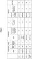
- Examples 1 to 3 and Comparative Example 1 are summarized in FIG. 3 .
- occurrence of cracks in the glass layer was checked after the multi-layer structures were left in an environment at a temperature of 60°C at a humidity of 95% for 12 hours.
Landscapes
- Physics & Mathematics (AREA)
- Thermal Sciences (AREA)
- Laminated Bodies (AREA)
Abstract
Description
- The present invention relates to a multi-layer structure.
- Multi-layered structures in which two or more layers are laminated have been known. In an example multi-layered structure, a silver reflection layer is laminated on a glass layer (glass film) having a small plate thickness. The thickness of this multi-layer structure is in the range of, for example, from 10 um through 200 um. This multi-layer structure is obtained from a glass roll formed by a downdraw method.
- Patent Document 1:
Japanese Unexamined Patent Application Publication No. 2013-231744 - Because of being extremely fragile, such a glass layer as described above that has a small plate thickness is easily cracked and has poor handleability. Therefore, for example, a proposed multi-layer structure is improved in handleability by reinforcement of the glass layer with, for example, a resin layer pasted on one side of the glass layer.
- However, when the multi-layer structure is used repeatedly in a high-temperature environment or a high-temperature, high-humidity environment, there have been cases where the glass layer is cracked.
- The present invention is made in view of the respect described above, and an object of the present invention is to provide a multi-layer structure in which a glass layer is not easily cracked.
- A multi-layer structure according to an embodiment includes a support, a resin layer laminated on the support via a tackifier layer, and a glass layer laminated over the resin layer. The thickness of the glass layer is 10 um or greater and 300 um or less. When the coefficient of linear expansion of the support is defined as CTE [ppm/°C], the thickness of the tackifier layer is defined as d [pm], and the elastic modulus of the tackifier layer is defined as E [GPa], the value a, which is defined as a=CTE/(d/E), is 3 or less.
- According to the disclosed technique, it is possible to provide a multi-layer structure in which a glass layer is not easily cracked.
-
- [
FIG. 1] FIG. 1 is a cross-sectional view illustrating a multi-layer structure according to an embodiment. - [
FIG. 2] FIG. 2 is a graph plotting a relationship between thickness/elastic modulus of a tackifier layer and a coefficient of linear expansion of a support. - [
FIG. 3] FIG. 3 is a diagram illustrating conditions and results of Examples and Comparative Example. - An embodiment for carrying out the invention will be described below with reference to the drawings. The same components in the diagrams will be denoted by the same reference numerals, and overlapping descriptions about such components may be skipped.
-
FIG. 1 is a cross-sectional view illustrating a multi-layer structure according to an embodiment. As illustrated inFIG. 1 , themulti-layer structure 1 includes asupport 10, atackifier layer 20, aresin layer 30, ametal layer 40, anadhesive layer 50, and aglass layer 60. Thetackifier layer 20, theresin layer 30, themetal layer 40, theadhesive layer 50, and theglass layer 60 are laminated in this order on anupper surface 10a of thesupport 10. - The planar shape of the multi-layer structure 1 (i.e., a shape seen in a direction of the normal to the
upper surface 10a of the support 10) is, for example, a rectangular shape. However, the planar shape of themulti-layer structure 1 is not limited to this, and may be a circular shape, an elliptical shape, any combinations of these shapes, and other appropriate shapes. - The
multi-layer structure 1 can be used as, for example, a mirror. In themulti-layer structure 1, the thickness of theglass layer 60 is 10 um or greater and 300 um or less. In themulti-layer structure 1, theglass layer 60 is thin, and the surface of theglass layer 60 and themetal layer 40 are extremely close to each other. Therefore, themulti-layer structure 1 can reflect a clear image by solving the problem of existing sheet glass, i.e., an image being reflected doubly. - Here, the material and other particulars of each component of the
multi-layer structure 1 will be described. - The
support 10 supports theresin layer 30 and theglass layer 60. The thickness of thesupport 10 may be, for example, approximately 1 mm or greater and 5 mm or less. The coefficient of linear expansion of thesupport 10 is preferably 100 ppm/°C or lower. Examples of the material of thesupport 10 include resins, glass, and metals. It is preferable that the coefficient of linear expansion of thesupport 10 be less. In this respect, it is preferable to use glass and metals as the material of thesupport 10. - Meanwhile, in terms of improving handleability of the
multi-layer structure 1, it is preferable to form thesupport 10 using a lightweight material. In this case, the weight of thesupport 10 per unit area is preferably 8 kg/m2 or less. In this case, it is possible to form thesupport 10 using a resin material, and it is preferable to select a resin material having a low coefficient of linear expansion. Examples of the resin material having a low coefficient of linear expansion include low-shrinkage acrylic-based resins produced by a melting film-formation method without stretching, and low-shrinkage polycarbonate-based resins produced by a stretching method. - The
tackifier layer 20 is provided between thesupport 10 and theresin layer 30. As thetackifier layer 20, a desirably selected appropriate tackifier is used. Examples of the material of thetackifier layer 20 include acrylic-based tackifiers, silicone-based tackifiers, and rubber-based tackifiers. The thickness of thetackifier layer 20 is not particularly limited, and is, for example, approximately 5 um or greater and 500 um or less. - The
resin layer 30 is laminated on thesupport 10 via thetackifier layer 20. Theresin layer 30 is formed of one layer or a plurality of layers. When theresin layer 30 is formed of a plurality of layers, it is preferable that the plurality of layers be laminated via a closely adhesive layer having an adhesive function. The total thickness of theresin layer 30 needs to at least be 20 um or greater and 1,000 µm or less, and preferably 25 µm or greater and 500 µm or less, and more preferably 50 um or greater and 200 um or less in terms of flexibility. When theresin layer 30 is formed of one layer, the thickness of theresin layer 30 may be in the range of, for example, 20 µm or greater and 150 µm or less. - Examples of the material of the
resin layer 30 include polyester-based resins such as polyethylene terephthalate-based resins and polyethylene naphthalate-based resins, cycloolefin-based resins such as norbornene-based resins, polyether sulfone-based resins, polycarbonate-based resins, acrylic-based resins, polyolefin-based resins, polyimide-based resins, polyamide-based resins, polyimide amide-based resins, polyarylate-based resins, polysulfone-based resins, polyether imide-based resins, cellulose-based resins, and urethane-based resins. - The
metal layer 40 is laminated on theresin layer 30. Themetal layer 40 is a layer that reflects visible light incident thereto through theglass layer 60 and theadhesive layer 50. As the material of themetal layer 40, a material having a high visible light reflectance is preferable. Examples of such a material include aluminum, silver, and silver alloys. The thickness of themetal layer 40 is not particularly limited, and is, for example, approximately 10 nm or greater and 500 nm or less. It is possible to form themetal layer 40 on the upper surface of theresin layer 30 by, for example, a sputtering method, a vapor deposition method, and a plating method. - The
metal layer 40 may be formed on the lower surface of theglass layer 60. In such a case, thetackifier layer 20, theresin layer 30, theadhesive layer 50, themetal layer 40, and theglass layer 60 are laminated in this order on theupper surface 10a of thesupport 10. It is possible to form themetal layer 40 on the lower surface of theglass layer 60 by, for example, a sputtering method, a vapor deposition method, and a plating method. - However, it is only necessary to provide the
metal layer 40 as the necessity arises. When themulti-layer structure 1 is free of themetal layer 40, themulti-layer structure 1 can be used as, for example, a lightweight glass board having texture and hardness of glass. - The
adhesive layer 50 is formed of a material having a high visible light transmittance. The thickness of theadhesive layer 50 is, for example, 0.1 um or greater and 25 um or less. As theadhesive layer 50, for example, acrylic-based tackifiers, silicone-based tackifiers, rubber-based tackifiers, ultraviolet-curable acrylic-based adhesives, ultraviolet-curable epoxy-based adhesives, thermosetting epoxy-based adhesives, thermosetting melamine-based adhesives, thermosetting phenol-based adhesives, ethylene vinyl acetate (EVA) interlayers, and polyvinyl butyral (PVB) interlayers can be used. - In the present specification, a tackifier represents a layer that has an adhesive property at normal temperature and adheres to an adhesion target at a low pressure. Hence, even when the adhesion target adhering to the tackifier is peeled, the tackifier has a practical tackifying force. On the other hand, an adhesive represents a layer that can bond substances by existing between the substances. Hence, when an adhesion target adhering to the adhesive is peeled, the adhesive does not have a practical adhesive force.
- The
glass layer 60 is laminated on themetal layer 40 via theadhesive layer 50. Theglass layer 60 is not particularly limited, and an appropriate material can be used in accordance with the intended purpose. Examples of the material of theglass layer 60 according to compositional classification include soda lime glass, borate glass, aluminosilicate glass, and quartz glass. Examples of the material of theglass layer 60 according to alkali component classification include alkali-free glass and low alkali glass. The content of an alkali metal component (e.g., Na2O, K2O, and Li2O) in the glass is preferably 15% by weight or less and more preferably 10% by weight or less. - The thickness of the
glass layer 60 is preferably 10 um or greater, considering surface hardness, airtightness, and corrosion resistance of glass. Moreover, because it is preferable that theglass layer 60 has such a flexibility as that of a film, the thickness of theglass layer 60 is preferably 300 um or less. The thickness of theglass layer 60 is more preferably 20 um or greater and 200 um or less, and particularly preferably 30 um or greater and 150 um or less. - The transmittance of light having a wavelength of 550 nm through the
glass layer 60 is preferably 85% or higher. The index of refraction of a wavelength of 550 nm through theglass layer 60 is preferably from 1.4 through 1.65. The density of theglass layer 60 is preferably from 2.3 g/cm3 through 3.0 g/cm3, and more preferably from 2.3 g/cm3 through 2.7 g/cm3 . - The method for forming the
glass layer 60 is not particularly limited, and an appropriate method may be employed in accordance with the intended purpose. Representatively, it is possible to produce theglass layer 60 by melting a mixture including a main material such as silica and alumina, a defoamer such as mirabilite and antimony oxide, and a reductant such as carbon at a temperature of approximately from 1,400°C through 1,600°C, forming the resulting product into a thin plate shape, and then cooling the resulting product. Examples of the method for forming theglass layer 60 include a slot downdraw method, a fusion method, and a float method. It is optional to chemically polish the glass layer, which has been formed into a sheet shape by any such method as described above, using a solvent such as hydrofluoric acid as needed, for formation into a sheet shape or improvement of smoothness. - Functional layers such as a stain-resistant layer, an antireflection layer, an electroconductive layer, a reflection layer, and a decorative layer may be provided on the upper surface of the glass layer 60 (i.e., the surface on which the
adhesive layer 50 is not formed). - When the
glass layer 60 is thin, handleability is poor. Therefore, theglass layer 60 may be easily cracked. Hence, in themulti-layer structure 1, thesupport 10 is provided at the undermost layer, to improve handleability. - Glass may be used as the
support 10. However, because glass is heavy, this increases the weight of the entirety of themulti-layer structure 1 and worsens handleability. Hence, when handleability is important, it is preferable to form thesupport 10 using a resin material. - However, in the case where a resin material is used as the
support 10, the resin material thermally expands when themulti-layer structure 1 is used in a high-temperature environment (e.g., 80°C) or in a high-temperature, high-humidity environment (e.g., 60°C 95%). Hence, without any countermeasure, theglass layer 60 may be locally deformed and theglass layer 60 may be cracked due to thermal expansion of the resin material through repeated use of themulti-layer structure 1 in a high-temperature environment or in a high-temperature, high-humidity environment. - Hence, a countermeasure is taken in the
multi-layer structure 1, so that theglass layer 60 is not cracked even when a resin material is used as thesupport 10. This will be described below. Because theresin layer 30 is bonded to theglass layer 60 via theadhesive layer 50, theresin layer 30 exhibits substantially the same behaviors as those of theglass layer 60. Hence, thermal expansion of theresin layer 30 can be ignored in terms of cracks in theglass layer 60. - The present inventors have repeatedly conducted studies into an idea of relieving the effects of thermal expansion of the
support 10 on theglass layer 60, by making thetackifier layer 20 absorb the thermal expansion of thesupport 10, and have discovered a relationship as plotted inFIG. 2. FIG. 2 is a graph plotting a relationship between thickness d [pm]/elastic modulus E [GPa] of thetackifier layer 20 and the coefficient of linear expansion CTE [ppm/°C] of thesupport 10. - In
FIG. 2 , followability of thetackifier layer 20 to thermal expansion of thesupport 10 is greater, the further the position on the horizontal axis representing thickness d [pm]/elastic modulus E [GPa] is in the direction of the arrow (rightward), and thermal expansion deformation of thesupport 10 is greater, the further the position on the vertical axis representing the coefficient of linear expansion CTE [ppm/°C] is in the direction of the arrow (upward). - The oblique line in
FIG. 2 represents a = CTE [ppm/°C]/(thickness d [pm]/elastic modulus E [GPa]). In the regions (1) and (2) below the oblique line inFIG. 2 , theglass layer 60 will not be cracked. On the other hand, in the region (3) above the oblique line inFIG. 2 , theglass layer 60 will be cracked. - That is, when CTE [ppm/°C] of the
support 10 is low, theglass layer 60 will not be cracked even when thickness d [pm]/elastic modulus E [GPa] of thetackifier layer 20 is low. Even when CTE [ppm/°C] of thesupport 10 is high, increasing thickness d [pm]/elastic modulus E [GPa] of thetackifier layer 20 can relieve thermal expansion of thesupport 10, so theglass layer 60 will not be cracked. - The region (1) represents a property obtained when glass is used as the
support 10. The region (2) represents a property obtained when a resin material is used as thesupport 10. That is, when glass is used as thesupport 10, theglass layer 60 will not be cracked irrespective of whether thickness d [pm]/elastic modulus E [GPa] of thetackifier layer 20 is high or low. As compared with this, when a resin material is used as thesupport 10, by adjusting thickness d [pm]/elastic modulus E [GPa] of thetackifier layer 20 such that it has a value that is below the oblique line ofFIG. 2 in view of the coefficient of linear expansion of the resin material, it is possible to inhibit cracks in theglass layer 60. - According to the present inventors' studies, it is possible to inhibit cracks in the
glass layer 60 due to thermal expansion of thesupport 10, when a = CTE [ppm/°C]/(thickness d [pm]/elastic modulus E [GPa]) is 3 or less. When glass is used as thesupport 10, the value of a is approximately 0.3. When a resin material is used as thesupport 10, the value of a is 1 or greater. - Hence, when heaviness of the
multi-layer structure 1 is tolerable to a certain degree, it is preferable to select thesupport 10 and thetackifier layer 20 such that the value of a becomes 0.2 or greater and 3 or less. On the other hand, in order to reduce the weight of themulti-layer structure 1, it is necessary to use a resin material as thesupport 10. In this case, it is preferable to select thesupport 10 and thetackifier layer 20 such that the value of a becomes 1 or greater and 3 or less. In any case, it is possible to inhibit cracks in theglass layer 60 so long as a≤3. - In terms of securely inhibiting cracks in the
glass layer 60, the coefficient of linear expansion of thesupport 10 is preferably 5 [ppm/°C] ≤ CTE ≤ 100 [ppm/°C]. The thickness of thetackifier layer 20 is preferably d≥50 [um], preferably d≥100 [pm], and more preferably d≥150 [pm]. - In Example 1, a multi-layer structure having the structure illustrated in
FIG. 1 was produced, to look into handleability and occurrence of cracks in the glass layer. In the multi-layer structure produced in Example 1, OA-10G obtained from Nippon Electric Glass Co., Ltd. was used as the material of the glass layer, and the thickness of the glass layer was set to approximately 100 um. An acrylic-based resin was used as the material of the tackifier layer, and thickness and elastic modulus of the tackifier layer were set to approximately 100 um and approximately 3 [GPa] respectively. An acrylic-based resin was used as the material of the support, and the coefficient of linear expansion of the support was set to 70 ppm/°C. In this case, a=2.1 [GPa•ppm/°C•um]. - In Example 2, a multi-layer structure having the structure illustrated in
FIG. 1 was produced, to look into handleability and occurrence of cracks in the glass layer. In the multi-layer structure produced in Example 2, OA-10G obtained from Nippon Electric Glass Co., Ltd. was used as the material of the glass layer, and the thickness of the glass layer was set to approximately 100 um. An acrylic-based resin was used as the material of the tackifier layer, and thickness and elastic modulus of the tackifier layer were set to approximately 100 um and approximately 3 [GPa] respectively. Sheet glass was used as the material of the support, and the coefficient of linear expansion of the support was set to 9 ppm/°C. In this case, a=0.3 [GPa•ppm/°C•µm]. - In Example 3, a multi-layer structure having the structure illustrated in
FIG. 1 was produced, to look into handleability and occurrence of cracks in the glass layer. In the multi-layer structure produced in Example 3, OA-10G obtained from Nippon Electric Glass Co., Ltd. was used as the material of the glass layer, and the thickness of the glass layer was set to approximately 100 um. An acrylic-based resin was used as the material of the tackifier layer, and thickness and elastic modulus of the tackifier layer were set to approximately 150 um and approximately 3 [GPa] respectively. An acrylic-based resin was used as the material of the support, and the coefficient of linear expansion of the support was set to 70 ppm/°C. In this case, a=1.4 [GPa•ppm/°C•um]. - In Comparative Example 1, a multi-layer structure having the structure illustrated in
FIG. 1 was produced, to look into handleability and occurrence of cracks in the glass layer. In the multi-layer structure produced in Comparative Example 1, OA-10G obtained from Nippon Electric Glass Co., Ltd. was used as the material of the glass layer, and the thickness of the glass layer was set to approximately 100 um. An acrylic-based resin was used as the material of the tackifier layer, and thickness and elastic modulus of the tackifier layer were set to approximately 30 um and approximately 3 [GPa] respectively. An acrylic-based resin was used as the material of the support, and the coefficient of linear expansion of the support was set to 70 ppm/°C. In this case, a=7.0 [GPa•ppm/°C•um]. - The conditions and results of Examples 1 to 3 and Comparative Example 1 are summarized in
FIG. 3 . In all of Examples 1 to 3 and Comparative Example 1, occurrence of cracks in the glass layer was checked after the multi-layer structures were left in an environment at a temperature of 60°C at a humidity of 95% for 12 hours. - From
FIG. 3 , it was successfully confirmed that the glass layer was not cracked when a≤3. For better improvement of handleability, it is appropriate to conclude that use of a resin material as the support is preferable. - Preferred embodiments and other particulars have been described in detail above. However, the embodiments and other particulars described above are not intended in a limiting sense, and various modifications and replacements can be made to the embodiments and other particulars described above without departing from the scope described in the claims.
- This international application is based on and claims priority to
Japanese Patent Application No. 2020-196632, filed November 27, 2020 Japanese Patent Application No. 2020-196632 -
- 1 multi-layer structure
- 10 support
- 10a upper surface
- 20 tackifier layer
- 30 resin layer
- 40 metal layer
- 50 adhesive layer
- 60 glass layer
Claims (8)
- A multi-layer structure, comprising:a support;a resin layer laminated on the support via a tackifier layer; anda glass layer laminated over the resin layer,wherein a thickness of the glass layer is 10 um or greater and 300 um or less, andwhen a coefficient of linear expansion of the support is defined as CTE [ppm/°C], thickness of the tackifier layer is defined as d [pm], and elastic modulus of the tackifier layer is defined as E [GPa], a value a, which is defined as a = CTE/(d/E), is 3 or less.
- The multi-layer structure according to claim 1,
wherein the CTE is 100 ppm/°C or lower. - The multi-layer structure according to claim 1 or 2,
wherein the d is 50 um or greater. - The multi-layer structure according to any one of claims 1 to 3,
wherein a weight of the support per unit area is 8 kg/m2 or less. - The multi-layer structure according to claim 4,
wherein the value of a is 1 or greater. - The multi-layer structure according to claim 5,
wherein the support is formed of a resin material. - The multi-layer structure according to claim 6,
wherein the resin material is an acrylic-based resin or a polycarbonate-based resin. - The multi-layer structure according to any one of claims 1 to 7, further comprising:
a metal layer laminated between the resin layer and the glass layer.
Applications Claiming Priority (2)
| Application Number | Priority Date | Filing Date | Title |
|---|---|---|---|
| JP2020196632A JP2022085125A (en) | 2020-11-27 | 2020-11-27 | Multilayer structure |
| PCT/JP2021/040086 WO2022113652A1 (en) | 2020-11-27 | 2021-10-29 | Multi-layer structure |
Publications (2)
| Publication Number | Publication Date |
|---|---|
| EP4253042A1 true EP4253042A1 (en) | 2023-10-04 |
| EP4253042A4 EP4253042A4 (en) | 2024-05-22 |
Family
ID=81754362
Family Applications (1)
| Application Number | Title | Priority Date | Filing Date |
|---|---|---|---|
| EP21897628.0A Withdrawn EP4253042A4 (en) | 2020-11-27 | 2021-10-29 | Multi-layer structure |
Country Status (7)
| Country | Link |
|---|---|
| US (1) | US20240001651A1 (en) |
| EP (1) | EP4253042A4 (en) |
| JP (1) | JP2022085125A (en) |
| KR (1) | KR20230111608A (en) |
| CN (1) | CN116568500A (en) |
| TW (1) | TW202224931A (en) |
| WO (1) | WO2022113652A1 (en) |
Families Citing this family (2)
| Publication number | Priority date | Publication date | Assignee | Title |
|---|---|---|---|---|
| JP2025056805A (en) * | 2022-02-28 | 2025-04-09 | 日東電工株式会社 | Multi-layer structure |
| JP2024139426A (en) * | 2023-03-27 | 2024-10-09 | 日東電工株式会社 | Multi-layer structure |
Family Cites Families (12)
| Publication number | Priority date | Publication date | Assignee | Title |
|---|---|---|---|---|
| JP2013231744A (en) | 2010-08-20 | 2013-11-14 | Konica Minolta Advanced Layers Inc | Film mirror, manufacturing method of the same, and sunlight reflecting mirror using the same |
| CN105358320B (en) * | 2012-08-31 | 2021-06-01 | 康宁股份有限公司 | Strengthened Thin Glass-Polymer Laminates |
| JP2015101044A (en) * | 2013-11-27 | 2015-06-04 | 日本電気硝子株式会社 | Chemically strengthened glass resin laminate and production method thereof |
| JP6645021B2 (en) | 2014-10-24 | 2020-02-12 | セイコーエプソン株式会社 | Medium transport unit, recording device |
| JP6613870B2 (en) * | 2015-07-17 | 2019-12-04 | 三菱ケミカル株式会社 | Glass laminate and protective material for display device |
| JP6544134B2 (en) * | 2015-08-17 | 2019-07-17 | 三菱ケミカル株式会社 | Glass laminate, glass laminate roll, substrate for electronic device, and glass layer protective film with release film |
| KR102010760B1 (en) * | 2015-10-26 | 2019-08-14 | 주식회사 엘지화학 | Optical device |
| WO2017135261A1 (en) * | 2016-02-01 | 2017-08-10 | 旭硝子株式会社 | Translucent structure |
| JP2016184180A (en) * | 2016-06-30 | 2016-10-20 | 日東電工株式会社 | Protective substrate for display device |
| CN110494282B (en) * | 2017-04-11 | 2022-02-22 | 富士胶片株式会社 | Optical laminate, front panel of image display device having optical laminate, image display device, resistive film type touch panel, and capacitive touch panel |
| CN111315573B (en) * | 2017-10-30 | 2023-01-13 | 日东电工株式会社 | Laminate for image display device |
| KR102679368B1 (en) * | 2018-07-09 | 2024-06-28 | 니혼 이타가라스 가부시키가이샤 | Glass plates suitable for image display devices |
-
2020
- 2020-11-27 JP JP2020196632A patent/JP2022085125A/en not_active Withdrawn
-
2021
- 2021-10-29 KR KR1020237019566A patent/KR20230111608A/en not_active Withdrawn
- 2021-10-29 US US18/038,070 patent/US20240001651A1/en not_active Abandoned
- 2021-10-29 CN CN202180078789.0A patent/CN116568500A/en active Pending
- 2021-10-29 WO PCT/JP2021/040086 patent/WO2022113652A1/en not_active Ceased
- 2021-10-29 EP EP21897628.0A patent/EP4253042A4/en not_active Withdrawn
- 2021-11-03 TW TW110141014A patent/TW202224931A/en unknown
Also Published As
| Publication number | Publication date |
|---|---|
| US20240001651A1 (en) | 2024-01-04 |
| TW202224931A (en) | 2022-07-01 |
| CN116568500A (en) | 2023-08-08 |
| KR20230111608A (en) | 2023-07-25 |
| JP2022085125A (en) | 2022-06-08 |
| EP4253042A4 (en) | 2024-05-22 |
| WO2022113652A1 (en) | 2022-06-02 |
Similar Documents
| Publication | Publication Date | Title |
|---|---|---|
| US9927893B2 (en) | Glass film laminate for touch panel, touch panel, and method of manufacturing glass film laminate for touch panel | |
| US20130114219A1 (en) | Opto-electronic frontplane substrate | |
| EP4253042A1 (en) | Multi-layer structure | |
| CN104718071A (en) | Surface-modified glass substrates | |
| WO2014129454A1 (en) | Glass laminate, optical imaging member, method for manufacturing glass laminate, and method for manufacturing optical imaging member | |
| US20240017527A1 (en) | Multi-layered structure and method for producing same | |
| JP2010208305A (en) | Laminated substrate, display device, manufacturing method of laminated substrate, and manufacturing method of display device | |
| EP4129649A1 (en) | Multilayer structure | |
| KR102846869B1 (en) | Method for manufacturing glass resin laminate | |
| US12233627B2 (en) | Thin glass laminated body | |
| EP4245523A1 (en) | Layered structure and method for producing same | |
| US20230278318A1 (en) | Multilayer structure | |
| EP4129648A1 (en) | Multilayer structure | |
| WO2023054282A1 (en) | Multi-layer structure | |
| JP2025056805A (en) | Multi-layer structure | |
| CN223355145U (en) | Water vapor barrier film | |
| JP2024139426A (en) | Multi-layer structure | |
| JP2024051582A (en) | Multi-layer structure | |
| JP2024007005A (en) | Functional film and glass laminate with adhesive layer |
Legal Events
| Date | Code | Title | Description |
|---|---|---|---|
| STAA | Information on the status of an ep patent application or granted ep patent |
Free format text: STATUS: THE INTERNATIONAL PUBLICATION HAS BEEN MADE |
|
| PUAI | Public reference made under article 153(3) epc to a published international application that has entered the european phase |
Free format text: ORIGINAL CODE: 0009012 |
|
| STAA | Information on the status of an ep patent application or granted ep patent |
Free format text: STATUS: REQUEST FOR EXAMINATION WAS MADE |
|
| 17P | Request for examination filed |
Effective date: 20230524 |
|
| AK | Designated contracting states |
Kind code of ref document: A1 Designated state(s): AL AT BE BG CH CY CZ DE DK EE ES FI FR GB GR HR HU IE IS IT LI LT LU LV MC MK MT NL NO PL PT RO RS SE SI SK SM TR |
|
| DAV | Request for validation of the european patent (deleted) | ||
| DAX | Request for extension of the european patent (deleted) | ||
| A4 | Supplementary search report drawn up and despatched |
Effective date: 20240423 |
|
| RIC1 | Information provided on ipc code assigned before grant |
Ipc: B32B 17/10 20060101AFI20240417BHEP |
|
| STAA | Information on the status of an ep patent application or granted ep patent |
Free format text: STATUS: THE APPLICATION IS DEEMED TO BE WITHDRAWN |
|
| 18D | Application deemed to be withdrawn |
Effective date: 20241114 |