EP4252729A1 - Space explorer rescue system - Google Patents
Space explorer rescue system Download PDFInfo
- Publication number
- EP4252729A1 EP4252729A1 EP23165940.0A EP23165940A EP4252729A1 EP 4252729 A1 EP4252729 A1 EP 4252729A1 EP 23165940 A EP23165940 A EP 23165940A EP 4252729 A1 EP4252729 A1 EP 4252729A1
- Authority
- EP
- European Patent Office
- Prior art keywords
- support pole
- support
- wheel
- pole
- space explorer
- Prior art date
- Legal status (The legal status is an assumption and is not a legal conclusion. Google has not performed a legal analysis and makes no representation as to the accuracy of the status listed.)
- Pending
Links
- 230000007246 mechanism Effects 0.000 claims description 8
- 238000004519 manufacturing process Methods 0.000 claims description 4
- 239000004744 fabric Substances 0.000 description 5
- 238000000034 method Methods 0.000 description 5
- 230000037396 body weight Effects 0.000 description 3
- 238000010586 diagram Methods 0.000 description 3
- 230000000694 effects Effects 0.000 description 3
- 239000003562 lightweight material Substances 0.000 description 3
- 101100109978 Arabidopsis thaliana ARP3 gene Proteins 0.000 description 2
- 101100163122 Arabidopsis thaliana ARPC2A gene Proteins 0.000 description 2
- CURLTUGMZLYLDI-UHFFFAOYSA-N Carbon dioxide Chemical compound O=C=O CURLTUGMZLYLDI-UHFFFAOYSA-N 0.000 description 2
- 101100191082 Saccharomyces cerevisiae (strain ATCC 204508 / S288c) GLC7 gene Proteins 0.000 description 2
- 101100427547 Saccharomyces cerevisiae (strain ATCC 204508 / S288c) ULS1 gene Proteins 0.000 description 2
- 101100030351 Schizosaccharomyces pombe (strain 972 / ATCC 24843) dis2 gene Proteins 0.000 description 2
- 101150117607 dis1 gene Proteins 0.000 description 2
- 239000000463 material Substances 0.000 description 2
- 229910052751 metal Inorganic materials 0.000 description 2
- 239000002184 metal Substances 0.000 description 2
- OKTJSMMVPCPJKN-UHFFFAOYSA-N Carbon Chemical compound [C] OKTJSMMVPCPJKN-UHFFFAOYSA-N 0.000 description 1
- 229920004943 Delrin® Polymers 0.000 description 1
- 208000027418 Wounds and injury Diseases 0.000 description 1
- 230000009471 action Effects 0.000 description 1
- 229910052782 aluminium Inorganic materials 0.000 description 1
- XAGFODPZIPBFFR-UHFFFAOYSA-N aluminium Chemical compound [Al] XAGFODPZIPBFFR-UHFFFAOYSA-N 0.000 description 1
- 229910052799 carbon Inorganic materials 0.000 description 1
- 229910002092 carbon dioxide Inorganic materials 0.000 description 1
- 239000001569 carbon dioxide Substances 0.000 description 1
- 239000002131 composite material Substances 0.000 description 1
- 230000006378 damage Effects 0.000 description 1
- 239000000835 fiber Substances 0.000 description 1
- 230000005484 gravity Effects 0.000 description 1
- 208000014674 injury Diseases 0.000 description 1
- 239000010985 leather Substances 0.000 description 1
- 230000004048 modification Effects 0.000 description 1
- 238000012986 modification Methods 0.000 description 1
- 230000008569 process Effects 0.000 description 1
- 230000009295 sperm incapacitation Effects 0.000 description 1
Images

Classifications
-
- B—PERFORMING OPERATIONS; TRANSPORTING
- B64—AIRCRAFT; AVIATION; COSMONAUTICS
- B64G—COSMONAUTICS; VEHICLES OR EQUIPMENT THEREFOR
- B64G1/00—Cosmonautic vehicles
- B64G1/22—Parts of, or equipment specially adapted for fitting in or to, cosmonautic vehicles
- B64G1/52—Protection, safety or emergency devices; Survival aids
-
- B—PERFORMING OPERATIONS; TRANSPORTING
- B64—AIRCRAFT; AVIATION; COSMONAUTICS
- B64G—COSMONAUTICS; VEHICLES OR EQUIPMENT THEREFOR
- B64G4/00—Tools specially adapted for use in space
-
- A—HUMAN NECESSITIES
- A61—MEDICAL OR VETERINARY SCIENCE; HYGIENE
- A61G—TRANSPORT, PERSONAL CONVEYANCES, OR ACCOMMODATION SPECIALLY ADAPTED FOR PATIENTS OR DISABLED PERSONS; OPERATING TABLES OR CHAIRS; CHAIRS FOR DENTISTRY; FUNERAL DEVICES
- A61G1/00—Stretchers
- A61G1/02—Stretchers with wheels
- A61G1/0206—Stretchers with wheels characterised by the number of supporting wheels if stretcher is extended
-
- A—HUMAN NECESSITIES
- A61—MEDICAL OR VETERINARY SCIENCE; HYGIENE
- A61G—TRANSPORT, PERSONAL CONVEYANCES, OR ACCOMMODATION SPECIALLY ADAPTED FOR PATIENTS OR DISABLED PERSONS; OPERATING TABLES OR CHAIRS; CHAIRS FOR DENTISTRY; FUNERAL DEVICES
- A61G1/00—Stretchers
- A61G1/013—Stretchers foldable or collapsible
-
- A—HUMAN NECESSITIES
- A61—MEDICAL OR VETERINARY SCIENCE; HYGIENE
- A61G—TRANSPORT, PERSONAL CONVEYANCES, OR ACCOMMODATION SPECIALLY ADAPTED FOR PATIENTS OR DISABLED PERSONS; OPERATING TABLES OR CHAIRS; CHAIRS FOR DENTISTRY; FUNERAL DEVICES
- A61G1/00—Stretchers
- A61G1/02—Stretchers with wheels
-
- A—HUMAN NECESSITIES
- A61—MEDICAL OR VETERINARY SCIENCE; HYGIENE
- A61G—TRANSPORT, PERSONAL CONVEYANCES, OR ACCOMMODATION SPECIALLY ADAPTED FOR PATIENTS OR DISABLED PERSONS; OPERATING TABLES OR CHAIRS; CHAIRS FOR DENTISTRY; FUNERAL DEVICES
- A61G1/00—Stretchers
- A61G1/02—Stretchers with wheels
- A61G1/0231—Stretchers with wheels having only fixed wheels
-
- A—HUMAN NECESSITIES
- A61—MEDICAL OR VETERINARY SCIENCE; HYGIENE
- A61G—TRANSPORT, PERSONAL CONVEYANCES, OR ACCOMMODATION SPECIALLY ADAPTED FOR PATIENTS OR DISABLED PERSONS; OPERATING TABLES OR CHAIRS; CHAIRS FOR DENTISTRY; FUNERAL DEVICES
- A61G1/00—Stretchers
- A61G1/02—Stretchers with wheels
- A61G1/0237—Stretchers with wheels having at least one swivelling wheel, e.g. castors
- A61G1/0243—Stretchers with wheels having at least one swivelling wheel, e.g. castors with lockable swivel action, e.g. fixing castor in certain direction
-
- A—HUMAN NECESSITIES
- A61—MEDICAL OR VETERINARY SCIENCE; HYGIENE
- A61G—TRANSPORT, PERSONAL CONVEYANCES, OR ACCOMMODATION SPECIALLY ADAPTED FOR PATIENTS OR DISABLED PERSONS; OPERATING TABLES OR CHAIRS; CHAIRS FOR DENTISTRY; FUNERAL DEVICES
- A61G1/00—Stretchers
- A61G1/02—Stretchers with wheels
- A61G1/025—Stretchers with wheels having auxiliary wheels, e.g. wheels not touching the ground in extended position
- A61G1/0268—Stretchers with wheels having auxiliary wheels, e.g. wheels not touching the ground in extended position having deployable or retractable wheels
-
- A—HUMAN NECESSITIES
- A61—MEDICAL OR VETERINARY SCIENCE; HYGIENE
- A61G—TRANSPORT, PERSONAL CONVEYANCES, OR ACCOMMODATION SPECIALLY ADAPTED FOR PATIENTS OR DISABLED PERSONS; OPERATING TABLES OR CHAIRS; CHAIRS FOR DENTISTRY; FUNERAL DEVICES
- A61G1/00—Stretchers
- A61G1/02—Stretchers with wheels
- A61G1/0281—Stretchers with wheels having a steering device
-
- A—HUMAN NECESSITIES
- A61—MEDICAL OR VETERINARY SCIENCE; HYGIENE
- A61G—TRANSPORT, PERSONAL CONVEYANCES, OR ACCOMMODATION SPECIALLY ADAPTED FOR PATIENTS OR DISABLED PERSONS; OPERATING TABLES OR CHAIRS; CHAIRS FOR DENTISTRY; FUNERAL DEVICES
- A61G1/00—Stretchers
- A61G1/04—Parts, details or accessories, e.g. head-, foot-, or like rests specially adapted for stretchers
-
- A—HUMAN NECESSITIES
- A61—MEDICAL OR VETERINARY SCIENCE; HYGIENE
- A61G—TRANSPORT, PERSONAL CONVEYANCES, OR ACCOMMODATION SPECIALLY ADAPTED FOR PATIENTS OR DISABLED PERSONS; OPERATING TABLES OR CHAIRS; CHAIRS FOR DENTISTRY; FUNERAL DEVICES
- A61G1/00—Stretchers
- A61G1/04—Parts, details or accessories, e.g. head-, foot-, or like rests specially adapted for stretchers
- A61G1/052—Struts, spars or legs
-
- B—PERFORMING OPERATIONS; TRANSPORTING
- B64—AIRCRAFT; AVIATION; COSMONAUTICS
- B64G—COSMONAUTICS; VEHICLES OR EQUIPMENT THEREFOR
- B64G1/00—Cosmonautic vehicles
Definitions
- the embodiments herein generally relate to space exploration equipment and more specifically, to a space explorer rescue system.
- Space explorers are tasked with exploring or visiting planets, moons, asteroids, or other celestial bodies.
- a space explorer may be an astronaut or any wearer of a space suit.
- a space explorer may experience an emergency during an extra vehicular activity on a celestial body that inhibits the ability of the space explorer to walk.
- the combined weight of a spacesuit in addition to the body weight of the space explorer may make it difficult for a fellow space explorer to carry the space explorer who cannot walk.
- a space explorer rescue system including: a stretcher including: a first support pole; a second support pole, the first support pole and the second support pole each being configured to be extended from a retracted position to a deployed position; and a body support extending between the first support pole and the second support pole; and at least one wheel attached or removably attached to the stretcher.
- Embodiments may include a control arm configured to attach the at least one wheel to the stretcher.
- Further embodiments may include a hinge configured to attach the control arm to the stretcher, the at least one wheel being configured to fold relative to the stretcher.
- the at least one wheel further includes: a first wheel attached to the first support pole; and a second wheel attached to the second support pole.
- FIG. 1 may depict a first control arm configured to attach the first wheel to the first support pole; and a second control arm configured to attach the second wheel to the second support pole.
- FIG. 1 Further embodiments may include: a first hinge configured to attach the first control arm to the first support pole, the first wheel being configured to fold relative to the stretcher; and a second hinge configured to attach the second control arm to the second support pole, the second wheel being configured to fold relative to the stretcher.
- first support pole is configured to telescope out of itself from the retracted position to the deployed position.
- the second support pole is configured to telescope out of itself from the retracted position to the deployed position.
- first support pole is configured to fold onto itself from the deployed position to the retracted position.
- the second support pole is configured to fold onto itself from the deployed position to the retracted position.
- Further embodiments may include: a primary life support system.
- the first support pole is configured to telescope into the primary support system from the deployed position to the retracted position.
- the second support pole is configured to telescope into the primary support system from the deployed position to the retracted position.
- Further embodiments may include: a primary life support system.
- the first support pole is configured to fold onto the primary support system from the deployed position to the retracted position.
- the second support pole is configured to fold onto the primary support system from the deployed position to the retracted position.
- FIG. 1 may depict a primary life support system including a structural framework.
- the first support pole is configured to attach to the structural framework.
- the second support pole is configured to attach to the structural framework.
- a primary life support system including a structural framework, the structural framework including a first external mounting point and a second external mounting point.
- the first support pole is configured to attach to the first external mounting point.
- the second support pole is configured to attach to the second external mounting point.
- first support pole is configured to attach directly to the first external mounting point.
- the second support pole is configured to attach directly to the second external mounting point.
- first support pole is configured to attach to the first external mounting point through a first extension pole.
- the second support pole is configured to attach to the second external mounting point through a second extension pole.
- first support pole and the second support pole each include a handle.
- inventions may include that the first support pole is oriented parallel to the second support pole.
- inventions may include that the body support is removably attached to at least one of the first support pole and the second support pole using an attachment mechanism.
- attachment mechanism is a snap or a strap.
- Further embodiments may include a compressed gas tank configured to provide compressed gas to inflate the at least one wheel.
- a method of manufacturing a space explorer rescue system including assembling a stretcher including the steps: deploying or attaching a first support pole; deploying or attaching a second support pole, the first support pole and second support pole each being configured to be extended from a retracted position to a deployed position; and deploying or attaching a body support to at least one of the first support pole and the second support pole, the body support being configured to extend between the first support pole and the second support pole; and deploying or attaching at least one wheel to the stretcher.
- space explorers are tasked with exploring planets, moons, asteroids, or other celestial bodies.
- a space explorer may be an astronaut or any wearer of a space suit.
- a space explorer may experience an emergency during an extra vehicular activity on a celestial body, that inhibits the ability of the space explorer to walk.
- the combined weight of the space suit and body weight may make it difficult for a fellow space explorer to carry the incapacitated space explorer. This problem is exacerbated if the incapacitated space explorer is much larger in size than the fellow space explorer, who must then move the incapacitated space explorer.
- Embodiments disclosed herein seek to provide a light weight and foldable stretcher with wheels which may be integrated into the spacesuit and can quickly unfold in the event of an emergency.
- a stretcher into the structure of the portable life support system (PLSS) or using available extension handles, this innovation provides a means for a space explorer to transport an injured companion to safety.
- PLSS portable life support system
- the space explorer rescue system 100 includes a stretcher 110 with at least one wheel 190. There may be two wheels 190 including a first wheel 190a and a second wheel 190b (e.g., see FIG. 2 ). While the space explorer rescue system 100 is described and illustrated throughout with first wheel 190a and a second wheel 190b, the embodiments disclosed herein may also be applicable to space explorer rescue systems 100 having only one wheel 190 or multiple wheels.
- the wheels 190 may be composed of rubber, a metal mesh or any other light weight material known to one of skill in the art.
- the wheels 190 may also be configured to inflate when deployment is required.
- storage and transportation of the wheels 190 in a deflated state would be easier as the wheels 190 would be lighter and take up less space.
- the wheels 190 may be inflated to be deployed using a compressed gas, such as, for example, carbon dioxide.
- the space explorer rescue system 100 may further optionally include a compressed gas tank 160 configured to provide compressed gas to inflate the wheel 190 when the space explorer rescue system 100 is deployed.
- the wheel 190 may also be configured to fold relative to the stretcher 110.
- the wheel 190 may also be removable from the stretcher 110, which may aid in storage and/or transportation.
- FIG. 1 illustrates a first space explorer 200 being carried on the space explorer rescue system 100 by a second space explorer 300.
- the first space explorer 200 may not be able to walk due to any type of incapacitation including but not limited to an illness, injury, or any other ailment.
- the second space explorer 300 may not be physically capable of carrying the first space explorer 200 due to the weight of the space suit 210 and the body weight of the first space explorer 200.
- the stretcher 110 may include a forward end 112 and an aft end 114 located opposite the forward end 112.
- the stretcher 110 may include a body support 120 configured to allow the first space explorer 200 to be carried thereon.
- the body support 120 may be a separate component or part of an internal structure of the PLSS.
- the body support 120 may be located at or proximate the aft end 114 along with the one or more wheels 190.
- the body support 120 may be composed of a flexible material, such as, for example a fabric of the same type covering the spacesuit (e.g., Orthofabric, oxford leather, or any other fabric known to one of skill in the art).
- the stretcher 110 may include two support poles 130 that extend from the forward end 112 to the aft end 114.
- the support poles 130 may include a first support pole 130a and a second support pole 130b that extends parallel to the first support pole 130a (e.g., see FIG. 2 ).
- the first support pole 130a and second support pole 130b are each configured to be extended from a retracted position to a deployed position.
- the support poles 130 are configured to provide structural rigidity to the stretcher 110.
- the support poles 130 may be composed of a strong light weight material, such as, for example, a metal, aluminum, a composite, carbon reinforced fiber, a plastic, Delrin, or any other strong light weight material known to one of skill in the art.
- the support poles 130 may include handles 136 located at or proximate the forward end 112.
- the handles 136 may be configured to allow the second space explorer to grasp onto the support pole 130 and lift the forward end 112 of the stretcher 110 in an upward direction D1.
- a control arm 194 connects the wheel 190 to the stretcher 110.
- the control arm 194 may specifically connects an axle 192 of the wheel 190 to the stretcher 110.
- the wheel 190 is configured to rotate around the axle 192.
- the control arm 194 may be connected to the stretcher 110 via a hinge 196.
- the hinge 196 is configured to fold the wheels 190 in for storage and out for use, as will be discussed further herein. Wheels may be detached and added as a separate action.
- the axle 192 of the wheel 190 may operate as a fulcrum of the space explorer rescue system 100 and thus as the second space explorer 300 lifts the forward end 112 of the stretcher 110 in the upward direction D1, the stretcher 110 pivots at axle 192.
- the control arm 194 may be connected to the stretcher 110 at a first distance DIS1 away from the forward end 112 and a second distance DIS2 away from the aft end 114.
- the first distance DIS1 may be greater than the second distance DIS2 to give the second space explorer 300 more leverage to lift the forward end 112 of the stretcher 110 in the upward direction D1.
- the space explorer rescue system 100 helps distributes the weight of the first space explorer 200 and the space suit 210 of the first space explorer 200 between the wheels 190 and the handles, thus reducing a total weight carried by the second space explorer 300.
- a center of gravity of the first space explorer 200 and the and the space suit 210 of the first space explorer 200 may or may not be placed over the wheels 190 for optimal performance.
- a space suit 310 of the second space explorer 300 may include a primary life support system 320 to be worn on a back 302 of the second space explorer 300.
- the primary life support system 320 includes a structural framework 322 and external mounting points 324 that may be integrally connected to or be part of the structural framework 322. Extensions poles 326 may be configured to connect the support poles 130 to the external mounting points 324, which advantageously will relieve load from hands 304 of the second space explorer 300 and may allow the second space explorer 300 to not have to grip the support poles 130 with any hands 304.
- the external mounting points 324 may be extravehicular mobility unit (EMU) Don/Doff Assembly (EDDA) mounting points. There may be a first or multiple external mounting point(s) 324 on a first side of the primary life support system 320 and a second or multiple external mounting point(s) 324 on a second side of the primary life support system 320.
- a space suit 210 of the first space explorer 200 may include a primary life support system 220 to be worn on a back 202 of the second space explorer 200.
- the primary life support system 220 includes a structural framework 222 and external mounting points 224 that may be integrally connected to or be part of the structural framework 322 (one or more each side, near side and far side). Extensions poles 326 may be configured to connect the support poles 130 to the external mounting points 224, eliminating the need to have telescoping poles in the PLSS.
- the external mounting points 224 may be extravehicular mobility unit (EMU) Don/Doff Assembly (EDDA) mounting points, which are designed to hold the weight of the spacesuit and space explorer.
- EMU extravehicular mobility unit
- EDDA Extravehicular mobility unit
- first or multiple external mounting point(s) 224 on a first side of the primary life support system 220 and a second or multiple external mounting point(s) 224 on a second side of the primary life support system 220.
- Fabric would be folded down from the PLSS or a strap would be fastened over the poles to support the space explorer's boots.
- a space suit 210 of the first space explorer 200 may include a primary life support system 220 to be worn on a back 202 of the first space explorer 200.
- the primary life support system 220 includes a structural framework 222 external mounting points 224 that may be integrally connected to or be part of the structural framework 222.
- the first space explorer 200 may be secured to the space explorer rescue system 100 via the external mounting points 224, which advantageously helps prevent the first space explorer from sliding off the body support 120.
- the first space explorer 200 may be secured to directly to the external mounting points 224.
- the external mounting points 224 may be EDDA mounting points. There may be a first external mounting point 224 on a first side of the primary life support system 220 and a second external mounting point 224 on a second side of the primary life support system 220.
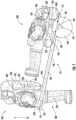
- FIG. 2 a top view of the space explorer rescue system 100 is illustrated in accordance with an embodiment of the present disclosure.
- the space explorer rescue system 100 includes the stretcher 110, a first wheel 190a, and a second wheel 192b.
- the first wheel 190a may be a left wheel and the second wheel 192b may be a right wheel.
- the stretcher 110 includes a first support pole 130a, a second support pole 130b that extends parallel to the first support pole 130a, and the body support 120 that extends between the first support pole 130a and the second support pole 130b.
- the first support pole 130a may be a left support and the second support pole 130b may be a right support pole.
- a first control arm 194a is configured to attach the first wheel 190a to the first support pole 130a.
- a first hinge 196a is configured to attach the first control arm 194a to the first support pole 130a.
- the first hinge 196a may be configured to allow the first control arm 194a to rotate relative to the first support pole 130a.
- a second control arm 194b is configured to attach the second wheel 190b to the second support pole 130b.
- a second hinge 196b is configured to attach the second control arm 194b to the second support pole 130b.
- the second hinge 196b may be configured to allow the second control arm 194b to rotate relative to the second support pole 130b.
- the first support pole 130a and the second support pole 130b may be configured to fold out or telescope out from a retracted position to a deployed position, as will be discussed further herein.
- the first support pole 130a and the second support pole 130b are illustrated in FIGS. 1 and 2 in the deployed position.
- Each support pole 130a, 130b may include one or more attachment mechanisms 150 configured to attach the body support 120 to the support poles 130a, 130b.
- the one or more attachment mechanisms 150 may be a strap, a snap, or any other similar attachment mechanism known to one of skill in the art.
- the body support 120 is removably attached to at least one of the first support pole 130a and the second support pole 130b using an attachment mechanism 150.
- the body support 120 may be a fabric that may be folded up and/or can be pulled down to extend to all points 150.
- the body support 120 may be small sections of fabric (e.g., strips), which may attach to the points 150.
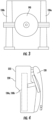
- FIGS. 3-4 a top view of the space explorer rescue system 100 in a retracted position is illustrated in FIG. 3 and a side view of the space explorer rescue system 100 in a retracted position is illustrated in FIG. 4 , in accordance with an embodiment of the present disclosure.
- the first support pole 130a is illustrated in FIGS. 3 and 4 in a retracted position.
- the first support pole 130a is retracted to the retracted position for ease of storage and transportation.
- the first support pole 130a may be configured to telescope into itself and/or into the structural framework 222 of the primary life support system 220 from a deployed position to a retracted position.
- the first support pole 130a may be configured to fold onto itself and/or onto the structural framework 222 of the primary life support system 220 from the deployed position to the retracted position.
- the first support pole is configured to telescope out of itself 130a and/or the primary life support system 220 from the retracted position to the deployed position.
- the second support pole 130b is illustrated in FIGS. 3 and 4 in a retracted position.
- the second support pole 130b is retracted to the retracted position for ease of storage and transportation.
- the second support pole 130b may be configured to telescope into itself and/or into the structural framework 222 of the primary life support system 220 from the deployed position to the retracted position.
- the second support pole 130b may be configured to fold onto itself and/or onto the structural framework 222 of the primary life support system 220 from the deployed position to the retracted position.
- the second support pole 130b is configured to telescope out of itself and/or the primary life support system 220 from the retracted position to the deployed position.
- the first support pole 130a and the second support pole 130b are in a retracted position, the wheels 190 may fold flat onto themselves about between the first support pole 130a and the second support pole 130b, as illustrated in FIG. 3 .
- the body support 120 may fold over the first support pole 130a, the second support pole 130b, and the wheels 190 in the retracted position to enclose the first support pole 130a, the second support pole 130b, and the wheels 190 between the body support 120 and the primary life support system 220 for storage and transportation.
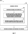
- FIG. 5 a flow diagram of a method 800 of manufacturing an space explorer rescue system 100 is illustrated in accordance with an embodiment of the present disclosure.
- a stretcher 110 is assembled comprising the steps of blocks 806, 808, 810.
- a first support pole 130a is deployed or attached.
- a second support pole 130b is deployed or attached.
- the first support pole 130a and second support pole 130b each being configured to be extended from a retracted position to a deployed position.
- a body support 120 is deployed or attached to at least one of the first support pole 130a and the second support pole 130b.
- the bodysupport 130 is configured to extend between the first support pole 130a and the second support pole 130b.
- At block 812 at least one wheel 190 is deployed or attached to the stretcher 110.
- the at least one wheel 190 may be configured to fold relative to the stretcher 110.
- a space explorer rescue system including a stretcher and one or more wheels configured to contract to a retracted position and extend to a deployed position.
Landscapes
- Health & Medical Sciences (AREA)
- General Health & Medical Sciences (AREA)
- Life Sciences & Earth Sciences (AREA)
- Animal Behavior & Ethology (AREA)
- Public Health (AREA)
- Veterinary Medicine (AREA)
- Engineering & Computer Science (AREA)
- Remote Sensing (AREA)
- Aviation & Aerospace Engineering (AREA)
- Critical Care (AREA)
- Emergency Medicine (AREA)
- Emergency Lowering Means (AREA)
- Professional, Industrial, Or Sporting Protective Garments (AREA)
Abstract
Description
- The embodiments herein generally relate to space exploration equipment and more specifically, to a space explorer rescue system.
- Space explorers are tasked with exploring or visiting planets, moons, asteroids, or other celestial bodies. A space explorer may be an astronaut or any wearer of a space suit. A space explorer may experience an emergency during an extra vehicular activity on a celestial body that inhibits the ability of the space explorer to walk. The combined weight of a spacesuit in addition to the body weight of the space explorer may make it difficult for a fellow space explorer to carry the space explorer who cannot walk.
- According to one aspect, a space explorer rescue system is provided. The space explorer rescue system including: a stretcher including: a first support pole; a second support pole, the first support pole and the second support pole each being configured to be extended from a retracted position to a deployed position; and a body support extending between the first support pole and the second support pole; and at least one wheel attached or removably attached to the stretcher.
- Embodiments may include a control arm configured to attach the at least one wheel to the stretcher.
- Further embodiments may include a hinge configured to attach the control arm to the stretcher, the at least one wheel being configured to fold relative to the stretcher.
- Further embodiments may include that the at least one wheel further includes: a first wheel attached to the first support pole; and a second wheel attached to the second support pole.
- Further embodiments may include: a first control arm configured to attach the first wheel to the first support pole; and a second control arm configured to attach the second wheel to the second support pole.
- Further embodiments may include: a first hinge configured to attach the first control arm to the first support pole, the first wheel being configured to fold relative to the stretcher; and a second hinge configured to attach the second control arm to the second support pole, the second wheel being configured to fold relative to the stretcher.
- Further embodiments may include that the first support pole is configured to telescope out of itself from the retracted position to the deployed position. The second support pole is configured to telescope out of itself from the retracted position to the deployed position.
- Further embodiments may include that the first support pole is configured to fold onto itself from the deployed position to the retracted position. The second support pole is configured to fold onto itself from the deployed position to the retracted position.
- Further embodiments may include: a primary life support system. The first support pole is configured to telescope into the primary support system from the deployed position to the retracted position. The second support pole is configured to telescope into the primary support system from the deployed position to the retracted position.
- Further embodiments may include: a primary life support system. The first support pole is configured to fold onto the primary support system from the deployed position to the retracted position. The second support pole is configured to fold onto the primary support system from the deployed position to the retracted position.
- Further embodiments may include: a primary life support system including a structural framework. The first support pole is configured to attach to the structural framework. The second support pole is configured to attach to the structural framework.
- Further embodiments may include: a primary life support system including a structural framework, the structural framework including a first external mounting point and a second external mounting point. The first support pole is configured to attach to the first external mounting point. The second support pole is configured to attach to the second external mounting point.
- Further embodiments may include that the first support pole is configured to attach directly to the first external mounting point. The second support pole is configured to attach directly to the second external mounting point.
- Further embodiments may include that the first support pole is configured to attach to the first external mounting point through a first extension pole. The second support pole is configured to attach to the second external mounting point through a second extension pole.
- Further embodiments may include that the first support pole and the second support pole each include a handle.
- Further embodiments may include that the first support pole is oriented parallel to the second support pole.
- Further embodiments may include that the body support is removably attached to at least one of the first support pole and the second support pole using an attachment mechanism.
- Further embodiments may include that the attachment mechanism is a snap or a strap.
- Further embodiments may include a compressed gas tank configured to provide compressed gas to inflate the at least one wheel.
- According to another aspect, a method of manufacturing a space explorer rescue system is provided. The method including assembling a stretcher including the steps: deploying or attaching a first support pole; deploying or attaching a second support pole, the first support pole and second support pole each being configured to be extended from a retracted position to a deployed position; and deploying or attaching a body support to at least one of the first support pole and the second support pole, the body support being configured to extend between the first support pole and the second support pole; and deploying or attaching at least one wheel to the stretcher.
- The foregoing features and elements may be combined in various combinations without exclusivity, unless expressly indicated otherwise. These features and elements as well as the operation thereof will become more apparent in light of the following description and the accompanying drawings. It should be understood, however, that the following description and drawings are intended to be illustrative and explanatory in nature and non-limiting.
- The following descriptions should not be considered limiting in any way. With reference to the accompanying drawings, like elements are numbered alike:
-
FIG. 1 is a schematic view of a space explorer rescue system in use, according to an embodiment of the present disclosure; -
FIG. 2 is a top view of the space explorer rescue system, according to an embodiment of the present disclosure; -
FIG. 3 is a top view of the space explorer rescue system in a retracted or non-deployed position, according to an embodiment of the present disclosure; -
FIG. 4 is a side view of the space explorer rescue system in the retracted or non-deployed position, according to an embodiment of the present disclosure; and -
FIG. 5 is a flow diagram illustrating a flow diagram of a method of manufacturing the space explorer rescue system, according to an embodiment of the present disclosure. - A detailed description of one or more embodiments of the disclosed apparatus and method are presented herein by way of exemplification and not limitation with reference to the Figures.
- The embodiments of the method and apparatus detailed herein relate to a space explorer rescue system. As aforementioned, space explorers are tasked with exploring planets, moons, asteroids, or other celestial bodies. A space explorer may be an astronaut or any wearer of a space suit. A space explorer may experience an emergency during an extra vehicular activity on a celestial body, that inhibits the ability of the space explorer to walk. The combined weight of the space suit and body weight may make it difficult for a fellow space explorer to carry the incapacitated space explorer. This problem is exacerbated if the incapacitated space explorer is much larger in size than the fellow space explorer, who must then move the incapacitated space explorer. Embodiments disclosed herein seek to provide a light weight and foldable stretcher with wheels which may be integrated into the spacesuit and can quickly unfold in the event of an emergency. Advantageously, by integrating a stretcher into the structure of the portable life support system (PLSS) or using available extension handles, this innovation provides a means for a space explorer to transport an injured companion to safety.
- Referring to
FIG. 1 , an isometric view of a spaceexplorer rescue system 100 is illustrated, in accordance with an embodiment of the present disclosure. The spaceexplorer rescue system 100 includes astretcher 110 with at least onewheel 190. There may be twowheels 190 including afirst wheel 190a and asecond wheel 190b (e.g., seeFIG. 2 ). While the spaceexplorer rescue system 100 is described and illustrated throughout withfirst wheel 190a and asecond wheel 190b, the embodiments disclosed herein may also be applicable to spaceexplorer rescue systems 100 having only onewheel 190 or multiple wheels. - The
wheels 190 may be composed of rubber, a metal mesh or any other light weight material known to one of skill in the art. Thewheels 190 may also be configured to inflate when deployment is required. Advantageously, storage and transportation of thewheels 190 in a deflated state would be easier as thewheels 190 would be lighter and take up less space. In one example, thewheels 190 may be inflated to be deployed using a compressed gas, such as, for example, carbon dioxide. For example, the spaceexplorer rescue system 100 may further optionally include acompressed gas tank 160 configured to provide compressed gas to inflate thewheel 190 when the spaceexplorer rescue system 100 is deployed. Thewheel 190 may also be configured to fold relative to thestretcher 110. Thewheel 190 may also be removable from thestretcher 110, which may aid in storage and/or transportation. -
FIG. 1 illustrates afirst space explorer 200 being carried on the spaceexplorer rescue system 100 by asecond space explorer 300. Thefirst space explorer 200 may not be able to walk due to any type of incapacitation including but not limited to an illness, injury, or any other ailment. Thesecond space explorer 300 may not be physically capable of carrying thefirst space explorer 200 due to the weight of thespace suit 210 and the body weight of thefirst space explorer 200. - The
stretcher 110 may include aforward end 112 and anaft end 114 located opposite theforward end 112. Thestretcher 110 may include abody support 120 configured to allow thefirst space explorer 200 to be carried thereon. Thebody support 120 may be a separate component or part of an internal structure of the PLSS. Thebody support 120 may be located at or proximate theaft end 114 along with the one ormore wheels 190. Thebody support 120 may be composed of a flexible material, such as, for example a fabric of the same type covering the spacesuit (e.g., Orthofabric, oxford leather, or any other fabric known to one of skill in the art). Thestretcher 110 may include twosupport poles 130 that extend from theforward end 112 to theaft end 114. Thesupport poles 130 may include afirst support pole 130a and asecond support pole 130b that extends parallel to thefirst support pole 130a (e.g., seeFIG. 2 ). Thefirst support pole 130a andsecond support pole 130b are each configured to be extended from a retracted position to a deployed position. - The
support poles 130 are configured to provide structural rigidity to thestretcher 110. Thesupport poles 130 may be composed of a strong light weight material, such as, for example, a metal, aluminum, a composite, carbon reinforced fiber, a plastic, Delrin, or any other strong light weight material known to one of skill in the art. - The
support poles 130 may includehandles 136 located at or proximate theforward end 112. Thehandles 136 may be configured to allow the second space explorer to grasp onto thesupport pole 130 and lift theforward end 112 of thestretcher 110 in an upward direction D1. - A
control arm 194 connects thewheel 190 to thestretcher 110. Thecontrol arm 194 may specifically connects anaxle 192 of thewheel 190 to thestretcher 110. Thewheel 190 is configured to rotate around theaxle 192. Thecontrol arm 194 may be connected to thestretcher 110 via ahinge 196. Thehinge 196 is configured to fold thewheels 190 in for storage and out for use, as will be discussed further herein. Wheels may be detached and added as a separate action. - The
axle 192 of thewheel 190 may operate as a fulcrum of the spaceexplorer rescue system 100 and thus as thesecond space explorer 300 lifts theforward end 112 of thestretcher 110 in the upward direction D1, thestretcher 110 pivots ataxle 192. Thecontrol arm 194 may be connected to thestretcher 110 at a first distance DIS1 away from theforward end 112 and a second distance DIS2 away from theaft end 114. The first distance DIS1 may be greater than the second distance DIS2 to give thesecond space explorer 300 more leverage to lift theforward end 112 of thestretcher 110 in the upward direction D1. - Advantageously, the space
explorer rescue system 100 helps distributes the weight of thefirst space explorer 200 and thespace suit 210 of thefirst space explorer 200 between thewheels 190 and the handles, thus reducing a total weight carried by thesecond space explorer 300. Advantageously, a center of gravity of thefirst space explorer 200 and the and thespace suit 210 of thefirst space explorer 200 may or may not be placed over thewheels 190 for optimal performance. - A
space suit 310 of thesecond space explorer 300 may include a primarylife support system 320 to be worn on a back 302 of thesecond space explorer 300. The primarylife support system 320 includes astructural framework 322 and external mounting points 324 that may be integrally connected to or be part of thestructural framework 322.Extensions poles 326 may be configured to connect thesupport poles 130 to the external mounting points 324, which advantageously will relieve load fromhands 304 of thesecond space explorer 300 and may allow thesecond space explorer 300 to not have to grip thesupport poles 130 with anyhands 304. The external mounting points 324 may be extravehicular mobility unit (EMU) Don/Doff Assembly (EDDA) mounting points. There may be a first or multiple external mounting point(s) 324 on a first side of the primarylife support system 320 and a second or multiple external mounting point(s) 324 on a second side of the primarylife support system 320. - FIG. 6 A
space suit 210 of thefirst space explorer 200 may include a primarylife support system 220 to be worn on a back 202 of thesecond space explorer 200. The primarylife support system 220 includes astructural framework 222 and external mounting points 224 that may be integrally connected to or be part of the structural framework 322 (one or more each side, near side and far side).Extensions poles 326 may be configured to connect thesupport poles 130 to the external mounting points 224, eliminating the need to have telescoping poles in the PLSS. The external mounting points 224 may be extravehicular mobility unit (EMU) Don/Doff Assembly (EDDA) mounting points, which are designed to hold the weight of the spacesuit and space explorer. There may be a first or multiple external mounting point(s) 224 on a first side of the primarylife support system 220 and a second or multiple external mounting point(s) 224 on a second side of the primarylife support system 220. Fabric would be folded down from the PLSS or a strap would be fastened over the poles to support the space explorer's boots. - A
space suit 210 of thefirst space explorer 200 may include a primarylife support system 220 to be worn on a back 202 of thefirst space explorer 200. The primarylife support system 220 includes astructural framework 222 external mounting points 224 that may be integrally connected to or be part of thestructural framework 222. Thefirst space explorer 200 may be secured to the spaceexplorer rescue system 100 via the external mounting points 224, which advantageously helps prevent the first space explorer from sliding off thebody support 120. Thefirst space explorer 200 may be secured to directly to the external mounting points 224. The external mounting points 224 may be EDDA mounting points. There may be a firstexternal mounting point 224 on a first side of the primarylife support system 220 and a secondexternal mounting point 224 on a second side of the primarylife support system 220. - Referring now to
FIG. 2 , with continued reference toFIG. 1 , a top view of the spaceexplorer rescue system 100 is illustrated in accordance with an embodiment of the present disclosure. - As aforementioned, the space
explorer rescue system 100 includes thestretcher 110, afirst wheel 190a, and a second wheel 192b. Thefirst wheel 190a may be a left wheel and the second wheel 192b may be a right wheel. Thestretcher 110 includes afirst support pole 130a, asecond support pole 130b that extends parallel to thefirst support pole 130a, and thebody support 120 that extends between thefirst support pole 130a and thesecond support pole 130b. Thefirst support pole 130a may be a left support and thesecond support pole 130b may be a right support pole. - A
first control arm 194a is configured to attach thefirst wheel 190a to thefirst support pole 130a. Afirst hinge 196a is configured to attach thefirst control arm 194a to thefirst support pole 130a. Thefirst hinge 196a may be configured to allow thefirst control arm 194a to rotate relative to thefirst support pole 130a. - A
second control arm 194b is configured to attach thesecond wheel 190b to thesecond support pole 130b. Asecond hinge 196b is configured to attach thesecond control arm 194b to thesecond support pole 130b. Thesecond hinge 196b may be configured to allow thesecond control arm 194b to rotate relative to thesecond support pole 130b. - The
first support pole 130a and thesecond support pole 130b may be configured to fold out or telescope out from a retracted position to a deployed position, as will be discussed further herein. Thefirst support pole 130a and thesecond support pole 130b are illustrated inFIGS. 1 and2 in the deployed position. - Each
support pole more attachment mechanisms 150 configured to attach thebody support 120 to thesupport poles more attachment mechanisms 150 may be a strap, a snap, or any other similar attachment mechanism known to one of skill in the art. Thebody support 120 is removably attached to at least one of thefirst support pole 130a and thesecond support pole 130b using anattachment mechanism 150. Alternately, thebody support 120 may be a fabric that may be folded up and/or can be pulled down to extend to all points 150. Another embodiment, thebody support 120 may be small sections of fabric (e.g., strips), which may attach to thepoints 150. - Referring now to
FIGS. 3-4 , with continued reference toFIGS. 1-2 , a top view of the spaceexplorer rescue system 100 in a retracted position is illustrated inFIG. 3 and a side view of the spaceexplorer rescue system 100 in a retracted position is illustrated inFIG. 4 , in accordance with an embodiment of the present disclosure. - The
first support pole 130a is illustrated inFIGS. 3 and 4 in a retracted position. Thefirst support pole 130a is retracted to the retracted position for ease of storage and transportation. Thefirst support pole 130a may be configured to telescope into itself and/or into thestructural framework 222 of the primarylife support system 220 from a deployed position to a retracted position. Thefirst support pole 130a may be configured to fold onto itself and/or onto thestructural framework 222 of the primarylife support system 220 from the deployed position to the retracted position. The first support pole is configured to telescope out of itself 130a and/or the primarylife support system 220 from the retracted position to the deployed position. - The
second support pole 130b is illustrated inFIGS. 3 and 4 in a retracted position. Thesecond support pole 130b is retracted to the retracted position for ease of storage and transportation. Thesecond support pole 130b may be configured to telescope into itself and/or into thestructural framework 222 of the primarylife support system 220 from the deployed position to the retracted position. Thesecond support pole 130b may be configured to fold onto itself and/or onto thestructural framework 222 of the primarylife support system 220 from the deployed position to the retracted position. Thesecond support pole 130b is configured to telescope out of itself and/or the primarylife support system 220 from the retracted position to the deployed position. - The
first support pole 130a and thesecond support pole 130b are in a retracted position, thewheels 190 may fold flat onto themselves about between thefirst support pole 130a and thesecond support pole 130b, as illustrated inFIG. 3 . Thebody support 120 may fold over thefirst support pole 130a, thesecond support pole 130b, and thewheels 190 in the retracted position to enclose thefirst support pole 130a, thesecond support pole 130b, and thewheels 190 between thebody support 120 and the primarylife support system 220 for storage and transportation. - Referring now to
FIG. 5 , with continued reference toFIGS. 1-4 , a flow diagram of amethod 800 of manufacturing an spaceexplorer rescue system 100 is illustrated in accordance with an embodiment of the present disclosure. - At
block 804, astretcher 110 is assembled comprising the steps ofblocks block 806, afirst support pole 130a is deployed or attached. Atblock 808, asecond support pole 130b is deployed or attached. Thefirst support pole 130a andsecond support pole 130b each being configured to be extended from a retracted position to a deployed position. Atblock 810, abody support 120 is deployed or attached to at least one of thefirst support pole 130a and thesecond support pole 130b. Thebodysupport 130 is configured to extend between thefirst support pole 130a and thesecond support pole 130b. - At
block 812, at least onewheel 190 is deployed or attached to thestretcher 110. The at least onewheel 190 may be configured to fold relative to thestretcher 110. - While the above description has described the flow process of
FIG. 5 in a particular order, it should be appreciated that unless otherwise specifically required in the attached claims that the ordering of the steps may be varied. - Technical effects and benefits of the features described herein include a space explorer rescue system including a stretcher and one or more wheels configured to contract to a retracted position and extend to a deployed position.
- The terminology used herein is for the purpose of describing particular embodiments only and is not intended to be limiting of the present disclosure. As used herein, the singular forms "a", "an" and "the" are intended to include the plural forms as well, unless the context clearly indicates otherwise. It will be further understood that the terms "comprises" and/or "comprising," when used in this specification, specify the presence of stated features, integers, steps, operations, elements, and/or components, but do not preclude the presence or addition of one or more other features, integers, steps, operations, element components, and/or groups thereof.
- While the present disclosure has been described with reference to an exemplary embodiment or embodiments, it will be understood by those skilled in the art that various changes may be made without departing from the scope of the invention as defined by the claims. In addition, many modifications may be made to adapt a particular situation or material to the teachings of the present disclosure without departing from the scope of the claims. Therefore, it is intended that the present disclosure not be limited to the particular embodiment disclosed as the best mode contemplated for carrying out this present disclosure, but that the present disclosure will include all embodiments falling within the scope of the claims.
Claims (15)
- A space explorer rescue system, comprising:
a stretcher (110) comprising:a first support pole (130a);a second support pole (130b), the first support pole and the second support pole each being configured to be extended from a retracted position to a deployed position; anda body support (120) extending between the first support pole and the second support pole; andat least one wheel (190) attached or removably attached to the stretcher. - The space explorer rescue system of claim 1, further comprising:
a control arm (194) configured to attach the at least one wheel to the stretcher. - The space explorer rescue system of claim 2, further comprising:
a hinge (196) configured to attach the control arm to the stretcher, the at least one wheel being configured to fold relative to the stretcher. - The space explorer rescue system of any preceding claim, wherein the at least one wheel further comprises:a first wheel (190a) attached to the first support pole; anda second wheel (190b) attached to the second support pole.
- The space explorer rescue system of claim 4, further comprising:a first control arm (194a) configured to attach the first wheel to the first support pole; anda second control arm (194b) configured to attach the second wheel to the second support pole; and optionally further comprising:a first hinge (196a) configured to attach the first control arm to the first support pole, the first wheel being configured to fold relative to the stretcher; anda second hinge (196b) configured to attach the second control arm to the second support pole, the second wheel being configured to fold relative to the stretcher.
- The space explorer rescue system of any preceding claim, wherein the first support pole is configured to telescope out of itself from the retracted position to the deployed position, andwherein the second support pole is configured to telescope out of itself from the retracted position to the deployed position; orwherein the first support pole is configured to fold onto itself from the deployed position to the retracted position, andwherein the second support pole is configured to fold onto itself from the deployed position to the retracted position.
- The space explorer rescue system of any preceding claim, further comprising:a primary life support system (220),wherein the first support pole is configured to telescope into the primary life support system from the deployed position to the retracted position, andwherein the second support pole is configured to telescope into the primary life support system from the deployed position to the retracted position.; orwherein the first support pole is configured to fold onto the primary life support system from the deployed position to the retracted position, andwherein the second support pole is configured to fold onto the primary life support system from the deployed position to the retracted position.
- The space explorer rescue system of any of claims 1 to 6, further comprising:a primary life support system (220) comprising a structural framework,wherein the first support pole is configured to attach to the structural framework, andwherein the second support pole is configured to attach to the structural framework.
- The space explorer rescue system of any of claims 1 to 6, further comprising:a primary life support system comprising a structural framework, the structural framework comprising a first external mounting point and a second external mounting point,wherein the first support pole is configured to attach to the first external mounting point, andwherein the second support pole is configured to attach to the second external mounting point.
- The space explorer rescue system of claim 9, wherein the first support pole is configured to attach directly to the first external mounting point, andwherein the second support pole is configured to attach directly to the second external mounting point; orwherein the first support pole is configured to attach to the first external mounting point through a first extension pole, andwherein the second support pole is configured to attach to the second external mounting point through a second extension pole.
- The space explorer rescue system of claim 8, wherein the first support pole and the second support pole each include a handle (136).
- The space explorer rescue system of any preceding claim, wherein the first support pole is oriented parallel to the second support pole.
- The space explorer rescue system of any preceding claim, wherein the body support is removably attached to at least one of the first support pole and the second support pole using an attachment mechanism (150), and optionally wherein the attachment mechanism is a snap or a strap.
- The space explorer rescue system of any preceding claim, further comprising:
a compressed gas tank (160) configured to provide compressed gas to inflate the at least one wheel. - A method of manufacturing a space explorer rescue system, comprising:
assembling a stretcher (110) comprising the steps:deploying or attaching a first support pole (130a);deploying or attaching a second support pole (130b), the first support pole and second support pole each being configured to be extended from a retracted position to a deployed position; anddeploying or attaching a body support (120) to at least one of the first support pole and the second support pole, the body support being configured to extend between the first support pole and the second support pole; anddeploying or attaching at least one wheel (190) to the stretcher.
Applications Claiming Priority (1)
| Application Number | Priority Date | Filing Date | Title |
|---|---|---|---|
| US17/711,648 US20230310234A1 (en) | 2022-04-01 | 2022-04-01 | Space explorer rescue system |
Publications (1)
| Publication Number | Publication Date |
|---|---|
| EP4252729A1 true EP4252729A1 (en) | 2023-10-04 |
Family
ID=86095933
Family Applications (1)
| Application Number | Title | Priority Date | Filing Date |
|---|---|---|---|
| EP23165940.0A Pending EP4252729A1 (en) | 2022-04-01 | 2023-03-31 | Space explorer rescue system |
Country Status (4)
| Country | Link |
|---|---|
| US (1) | US20230310234A1 (en) |
| EP (1) | EP4252729A1 (en) |
| KR (1) | KR20230142367A (en) |
| CN (1) | CN116889495A (en) |
Citations (3)
| Publication number | Priority date | Publication date | Assignee | Title |
|---|---|---|---|---|
| GB191211969A (en) * | 1912-05-21 | 1913-05-21 | Albert Joseph Perry | Collapsible and Convertible Stretcher or Chair. |
| DE202007013158U1 (en) * | 2007-09-18 | 2007-12-06 | Brandschutztechnik Müller GmbH | abrasive wear |
| US8789730B2 (en) * | 2007-10-16 | 2014-07-29 | David E. Mroczka | Backpack with collapsible stretcher and collapsible wheel assembly |
Family Cites Families (5)
| Publication number | Priority date | Publication date | Assignee | Title |
|---|---|---|---|---|
| CA2352979C (en) * | 2000-09-18 | 2007-09-11 | Charles W. Darling, Iii | Portable cart for wagon/stretcher |
| US20070075105A1 (en) * | 2005-10-04 | 2007-04-05 | Petrin Raymond R | Trailable backpack |
| US8087112B2 (en) * | 2009-01-12 | 2012-01-03 | Cahaan Dirk | Portable collapsible stretcher |
| IL198502A0 (en) * | 2009-05-03 | 2010-02-17 | Hava Bar Noy | Collapsible stretchar dragged on wheels |
| US20110099717A1 (en) * | 2009-11-02 | 2011-05-05 | Windauer Bernard T | Medical litter |
-
2022
- 2022-04-01 US US17/711,648 patent/US20230310234A1/en not_active Abandoned
-
2023
- 2023-03-31 CN CN202310345961.5A patent/CN116889495A/en active Pending
- 2023-03-31 EP EP23165940.0A patent/EP4252729A1/en active Pending
- 2023-03-31 KR KR1020230042546A patent/KR20230142367A/en active Pending
Patent Citations (3)
| Publication number | Priority date | Publication date | Assignee | Title |
|---|---|---|---|---|
| GB191211969A (en) * | 1912-05-21 | 1913-05-21 | Albert Joseph Perry | Collapsible and Convertible Stretcher or Chair. |
| DE202007013158U1 (en) * | 2007-09-18 | 2007-12-06 | Brandschutztechnik Müller GmbH | abrasive wear |
| US8789730B2 (en) * | 2007-10-16 | 2014-07-29 | David E. Mroczka | Backpack with collapsible stretcher and collapsible wheel assembly |
Also Published As
| Publication number | Publication date |
|---|---|
| KR20230142367A (en) | 2023-10-11 |
| US20230310234A1 (en) | 2023-10-05 |
| CN116889495A (en) | 2023-10-17 |
Similar Documents
| Publication | Publication Date | Title |
|---|---|---|
| US8789730B2 (en) | Backpack with collapsible stretcher and collapsible wheel assembly | |
| US20110119831A1 (en) | Foldable Patient Transport Surface | |
| US8590077B2 (en) | Hands-free emergency all-terrain light-weight litter | |
| US3336060A (en) | Collapsible supporting structures | |
| US5283916A (en) | Process for transporting injured or stranded people, and protective capsule for carrying out the process | |
| US20040088794A1 (en) | Emergency drag stretcher | |
| US5502854A (en) | Floating foldable stretcher designed, in particular, for the recovery of injured persons at sea | |
| US20200352802A1 (en) | Portable and collapsible support structures and related methods | |
| WO2003026949A2 (en) | Floatation system including life raft | |
| WO2015009327A1 (en) | Portable human transport system | |
| US20050210589A1 (en) | Compact foldable stretcher | |
| WO2013190552A1 (en) | Light weight multi use collapsible stretcher | |
| US9974701B1 (en) | Rapid intervention drag and lift stretcher device with leg protection, six point lift capability, and inflatable bladder support/floatation mechanism | |
| US20100282897A1 (en) | Unmanned Aerial Surveillance Device | |
| US6053534A (en) | Inflatable evacuation shuttle | |
| KR101954549B1 (en) | Stretcher | |
| US20200345155A1 (en) | Child carrier for luggage | |
| EP3760531A1 (en) | Flotation device with boarding apparatus | |
| US20230310234A1 (en) | Space explorer rescue system | |
| EP0067070B1 (en) | Stretcher | |
| US5499416A (en) | Floating stretcher designed, in particular, for the recovery of injured persons at sea | |
| US5067669A (en) | Portable landing zone for helicopters | |
| GB2213735A (en) | Means for support and transportation of injured patients. | |
| US20100084444A1 (en) | Lightweight Sitting Stretcher | |
| JP2011156328A (en) | Self-support type stretcher with wheel |
Legal Events
| Date | Code | Title | Description |
|---|---|---|---|
| PUAI | Public reference made under article 153(3) epc to a published international application that has entered the european phase |
Free format text: ORIGINAL CODE: 0009012 |
|
| STAA | Information on the status of an ep patent application or granted ep patent |
Free format text: STATUS: THE APPLICATION HAS BEEN PUBLISHED |
|
| AK | Designated contracting states |
Kind code of ref document: A1 Designated state(s): AL AT BE BG CH CY CZ DE DK EE ES FI FR GB GR HR HU IE IS IT LI LT LU LV MC ME MK MT NL NO PL PT RO RS SE SI SK SM TR |
|
| STAA | Information on the status of an ep patent application or granted ep patent |
Free format text: STATUS: REQUEST FOR EXAMINATION WAS MADE |
|
| 17P | Request for examination filed |
Effective date: 20240403 |
|
| RBV | Designated contracting states (corrected) |
Designated state(s): AL AT BE BG CH CY CZ DE DK EE ES FI FR GB GR HR HU IE IS IT LI LT LU LV MC ME MK MT NL NO PL PT RO RS SE SI SK SM TR |