EP4252685A1 - Expandable bone core for pedicle screw fixation - Google Patents
Expandable bone core for pedicle screw fixation Download PDFInfo
- Publication number
- EP4252685A1 EP4252685A1 EP23164926.0A EP23164926A EP4252685A1 EP 4252685 A1 EP4252685 A1 EP 4252685A1 EP 23164926 A EP23164926 A EP 23164926A EP 4252685 A1 EP4252685 A1 EP 4252685A1
- Authority
- EP
- European Patent Office
- Prior art keywords
- anchor
- expandable
- implant
- pedicle screw
- pedicle
- Prior art date
- Legal status (The legal status is an assumption and is not a legal conclusion. Google has not performed a legal analysis and makes no representation as to the accuracy of the status listed.)
- Withdrawn
Links
Images




Classifications
-
- A—HUMAN NECESSITIES
- A61—MEDICAL OR VETERINARY SCIENCE; HYGIENE
- A61B—DIAGNOSIS; SURGERY; IDENTIFICATION
- A61B17/00—Surgical instruments, devices or methods
- A61B17/56—Surgical instruments or methods for treatment of bones or joints; Devices specially adapted therefor
- A61B17/58—Surgical instruments or methods for treatment of bones or joints; Devices specially adapted therefor for osteosynthesis, e.g. bone plates, screws or setting implements
- A61B17/68—Internal fixation devices, including fasteners and spinal fixators, even if a part thereof projects from the skin
- A61B17/70—Spinal positioners or stabilisers, e.g. stabilisers comprising fluid filler in an implant
- A61B17/7001—Screws or hooks combined with longitudinal elements which do not contact vertebrae
- A61B17/7032—Screws or hooks with U-shaped head or back through which longitudinal rods pass
-
- A—HUMAN NECESSITIES
- A61—MEDICAL OR VETERINARY SCIENCE; HYGIENE
- A61B—DIAGNOSIS; SURGERY; IDENTIFICATION
- A61B17/00—Surgical instruments, devices or methods
- A61B17/56—Surgical instruments or methods for treatment of bones or joints; Devices specially adapted therefor
- A61B17/58—Surgical instruments or methods for treatment of bones or joints; Devices specially adapted therefor for osteosynthesis, e.g. bone plates, screws or setting implements
- A61B17/68—Internal fixation devices, including fasteners and spinal fixators, even if a part thereof projects from the skin
- A61B17/686—Plugs, i.e. elements forming interface between bone hole and implant or fastener, e.g. screw
-
- A—HUMAN NECESSITIES
- A61—MEDICAL OR VETERINARY SCIENCE; HYGIENE
- A61B—DIAGNOSIS; SURGERY; IDENTIFICATION
- A61B17/00—Surgical instruments, devices or methods
- A61B17/56—Surgical instruments or methods for treatment of bones or joints; Devices specially adapted therefor
- A61B17/58—Surgical instruments or methods for treatment of bones or joints; Devices specially adapted therefor for osteosynthesis, e.g. bone plates, screws or setting implements
- A61B17/68—Internal fixation devices, including fasteners and spinal fixators, even if a part thereof projects from the skin
- A61B17/70—Spinal positioners or stabilisers, e.g. stabilisers comprising fluid filler in an implant
-
- A—HUMAN NECESSITIES
- A61—MEDICAL OR VETERINARY SCIENCE; HYGIENE
- A61B—DIAGNOSIS; SURGERY; IDENTIFICATION
- A61B17/00—Surgical instruments, devices or methods
- A61B17/56—Surgical instruments or methods for treatment of bones or joints; Devices specially adapted therefor
- A61B17/58—Surgical instruments or methods for treatment of bones or joints; Devices specially adapted therefor for osteosynthesis, e.g. bone plates, screws or setting implements
- A61B17/68—Internal fixation devices, including fasteners and spinal fixators, even if a part thereof projects from the skin
- A61B17/84—Fasteners therefor or fasteners being internal fixation devices
- A61B17/844—Fasteners therefor or fasteners being internal fixation devices with expandable anchors or anchors having movable parts
-
- A—HUMAN NECESSITIES
- A61—MEDICAL OR VETERINARY SCIENCE; HYGIENE
- A61B—DIAGNOSIS; SURGERY; IDENTIFICATION
- A61B17/00—Surgical instruments, devices or methods
- A61B17/56—Surgical instruments or methods for treatment of bones or joints; Devices specially adapted therefor
- A61B17/58—Surgical instruments or methods for treatment of bones or joints; Devices specially adapted therefor for osteosynthesis, e.g. bone plates, screws or setting implements
- A61B17/68—Internal fixation devices, including fasteners and spinal fixators, even if a part thereof projects from the skin
- A61B17/84—Fasteners therefor or fasteners being internal fixation devices
- A61B17/86—Pins or screws or threaded wires; nuts therefor
- A61B17/8625—Shanks, i.e. parts contacting bone tissue
- A61B17/863—Shanks, i.e. parts contacting bone tissue with thread interrupted or changing its form along shank, other than constant taper
-
- A—HUMAN NECESSITIES
- A61—MEDICAL OR VETERINARY SCIENCE; HYGIENE
- A61B—DIAGNOSIS; SURGERY; IDENTIFICATION
- A61B17/00—Surgical instruments, devices or methods
- A61B17/56—Surgical instruments or methods for treatment of bones or joints; Devices specially adapted therefor
- A61B17/58—Surgical instruments or methods for treatment of bones or joints; Devices specially adapted therefor for osteosynthesis, e.g. bone plates, screws or setting implements
- A61B17/88—Osteosynthesis instruments; Methods or means for implanting or extracting internal or external fixation devices
- A61B17/8802—Equipment for handling bone cement or other fluid fillers
- A61B17/8847—Equipment for handling bone cement or other fluid fillers for removing cement from a bone cavity
-
- A—HUMAN NECESSITIES
- A61—MEDICAL OR VETERINARY SCIENCE; HYGIENE
- A61B—DIAGNOSIS; SURGERY; IDENTIFICATION
- A61B17/00—Surgical instruments, devices or methods
- A61B17/56—Surgical instruments or methods for treatment of bones or joints; Devices specially adapted therefor
- A61B17/58—Surgical instruments or methods for treatment of bones or joints; Devices specially adapted therefor for osteosynthesis, e.g. bone plates, screws or setting implements
- A61B17/88—Osteosynthesis instruments; Methods or means for implanting or extracting internal or external fixation devices
- A61B17/885—Tools for expanding or compacting bones or discs or cavities therein
- A61B17/8852—Tools for expanding or compacting bones or discs or cavities therein capable of being assembled or enlarged, or changing shape, inside the bone or disc
-
- A—HUMAN NECESSITIES
- A61—MEDICAL OR VETERINARY SCIENCE; HYGIENE
- A61F—FILTERS IMPLANTABLE INTO BLOOD VESSELS; PROSTHESES; DEVICES PROVIDING PATENCY TO, OR PREVENTING COLLAPSING OF, TUBULAR STRUCTURES OF THE BODY, e.g. STENTS; ORTHOPAEDIC, NURSING OR CONTRACEPTIVE DEVICES; FOMENTATION; TREATMENT OR PROTECTION OF EYES OR EARS; BANDAGES, DRESSINGS OR ABSORBENT PADS; FIRST-AID KITS
- A61F2/00—Filters implantable into blood vessels; Prostheses, i.e. artificial substitutes or replacements for parts of the body; Appliances for connecting them with the body; Devices providing patency to, or preventing collapsing of, tubular structures of the body, e.g. stents
- A61F2/02—Prostheses implantable into the body
- A61F2/30—Joints
- A61F2/44—Joints for the spine, e.g. vertebrae or spinal discs
-
- A—HUMAN NECESSITIES
- A61—MEDICAL OR VETERINARY SCIENCE; HYGIENE
- A61B—DIAGNOSIS; SURGERY; IDENTIFICATION
- A61B17/00—Surgical instruments, devices or methods
- A61B17/56—Surgical instruments or methods for treatment of bones or joints; Devices specially adapted therefor
- A61B17/58—Surgical instruments or methods for treatment of bones or joints; Devices specially adapted therefor for osteosynthesis, e.g. bone plates, screws or setting implements
- A61B17/68—Internal fixation devices, including fasteners and spinal fixators, even if a part thereof projects from the skin
- A61B17/84—Fasteners therefor or fasteners being internal fixation devices
- A61B17/86—Pins or screws or threaded wires; nuts therefor
- A61B2017/8655—Pins or screws or threaded wires; nuts therefor with special features for locking in the bone
Definitions
- the present disclosure relates to surgical devices, and more particularly, to pedicle bone anchors and associated methods.
- Common procedures for handling pain associated with intervertebral discs that have become degenerated due to various factors such as trauma or aging may include the use of pedicle screw fixation and/or intervertebral fusion for fusing one or more adjacent vertebral bodies.
- pedicle screw fixation for example, with a rod construct, may be used to treat degenerative disc disease and a multitude of other spine pathologies as a standard of treatment to stabilize two or more adjacent vertebral bodies.
- Pedicle screw morphology has evolved over time to further improve the primary stabilization of the screws.
- screw loosening is still a primary concern. This issue is exacerbated by patients with poor bone quality which is commonly associated with screw pullout at the ends of rod constructs.
- a specialized pedicle screw may be used in conjunction with an expandable press-fit bone anchor.
- the implant may include an expandable plug with teeth or anchors that eject into bone.
- the implant may include a pedicle screw with an expandable proximal portion configured to increase the purchase in the pedicle space.
- the expandable anchors are configured to increase and improve the integrity of the bone-implant interface.
- the implants may improve the primary stability, reduce the effects of micro motion, and/or facilitate osseointegration of the implant with the surrounding bone.
- an expandable implant includes an expandable anchor and a pedicle screw.
- the expandable anchor has a body with a plurality of expandable sections separated by one or more expansion joints.
- the anchor includes a central through hole arranged along a central longitudinal axis of the anchor.
- the pedicle screw has a head and a shaft. The pedicle screw is receivable in the expandable anchor.
- the expandable anchor has a collapsed configuration and an expanded configuration, thereby creating a press-fit in adjacent bone.
- the expandable implant may include one or more of the following features.
- the plurality of expandable sections may be configured to radially expand outward and away from one another, thereby increasing an outer diameter of the anchor. When the expandable sections are expanded apart, a width of each expansion joint may increase to enlarge the anchor.
- the expandable anchor may have a generally cylindrical shape.
- the expandable anchor may include four expandable sections each adjacent to one expansion joint.
- the expansion joints may include a malleable or flexible material.
- the central through hole may be internally threaded and configured to engage with corresponding threads along the shaft of the pedicle screw.
- the anchor may include a plurality of teeth arranged in an array about the periphery of the expandable sections. The teeth may be pyramidal in shape or otherwise configured to engage bone.
- the length of the expandable anchor may be shorter than the length of the pedicle screw and may be arranged along the distal end of the pedicle screw and secured in the vertebral body of the vertebra.
- an expandable implant with deployable teeth includes an enlarged head and a shank extending along a central longitudinal axis.
- the shank defines a center channel in fluid communication with a plurality of openings.
- the implant further includes a plurality of moveable teeth.
- Each tooth has an elongated body with an inner end receivable in the central channel and an outer end configured to eject from the openings in the shank.
- the teeth have a retracted position and deployed position whereby the teeth extend radially outward from the shank.
- the expandable implant may include one or more of the following features.
- the teeth may be positioned generally perpendicular to the central longitudinal axis of the shank.
- the inner end of each tooth may include an angled portion configured to help expand the teeth.
- the teeth may be arranged in a pattern around the periphery of the shank.
- the teeth may be ejected pneumatically, with a pressurized liquid, or with bone cement, for example.
- a method for stabilizing a vertebra includes one or more of the following steps in any suitable order: (1) posteriorly accessing a spine of a patient; (2) preparing a channel (e.g., a pair of bilateral channels) through a pedicle and a vertebral body of a vertebra; (3) inserting an expandable anchor through the channel and into the vertebral body of the vertebra, the anchor having a body with a plurality of expandable sections separated by one or more expansion joints, a central through hole, and a plurality of teeth arranged about the expandable sections; (4) expanding the expandable anchor to create a strong press-fit in the vertebra; and (5) inserting a pedicle screw through the channel into the central through hole of the expandable anchor and securing the pedicle screw to the expandable anchor.
- a channel e.g., a pair of bilateral channels
- the expandable anchor may be provided only at a distal region of the pedicle screw and within the vertebral body of the vertebra.
- the anchor may be expanded by an instrument before inserting the pedicle screw into the expanded anchor.
- insertion of the pedicle screw into the anchor simultaneously expands the anchor as the pedicle screw is threaded through the anchor.
- kits including pedicle implants of varying types and sizes, interbody fusion devices of varying types and sizes, rods, fasteners or anchors, k-wires, insertion tools, instruments, and other components for performing the procedure.
- Bilateral pedicle screw fixation may be used to treat degenerative disc disease and other spine pathologies.
- One or more expandable implants may be used to secure the device(s) within the pedicle and/or vertebral body of the vertebra.
- the expandable implants may include an assembly including an expandable anchor for receiving a pedicle screw, an expandable bone plug with deployable prongs or teeth, an expandable fastener with an expandable head and proximal shaft for receiving an expansion member, or other similar expansion mechanisms.
- the expandable configuration(s) may allow for unused pedicle space to be filled and utilized.
- the expandable implants may improve the primary stability of the construct, which may help to reduce the effects of micro motion and facilitate osseointegration of the implant with the surrounding bone.
- the terms device, fixation device, assembly, and implant may be used interchangeably herein.
- an orthopedic fixation assembly, pedicle bone fastener assembly, or implant 10 is shown implanted into vertebra 2.
- the method of fixation may include, for example, accessing the spine from the posterior and inserting the implant 10 into the pedicle 6 of the vertebra 2. If necessary, bone may be removed from the pedicle 6 and/or the vertebral body 4 in order to facilitate placement of the device 10.
- One or more pedicle devices 10 may be used alone or in conjunction with a traditional interbody fusion device. Although the method is shown with respect to a single pedicle 6, it will be appreciated that the other pedicle (not shown) may also receive the same or a similar device.
- a pair of implants 10 may be implanted bilaterally and angled medially toward one another in the vertebral body 4, but the final location and orientation of the devices 10 will be selected by a surgeon. It will also be appreciated that the same or similar devices may also be used on adjacent or other levels.
- the pedicle implant 10 may include an expandable bone anchor 12 and a pedicle screw 14.
- the expandable bone anchor 12 has a collapsed configuration, thereby allowing the anchor 12 to be inserted through the pedicle 6 and into the vertebral body 4 of the vertebra 2, for example, in a minimally invasive manner.
- the bone anchor 12 may be expanded into an expanded configuration, as best seen in FIG. 4 , thereby creating a strong press-fit in the bone.
- the anchor 12 may be placed in the pedicle 6 or cancellous bone only.
- the pedicle screw 14 may be inserted through the pedicle 6 and driven into the expanded bone anchor 12 to complete the final assembly 10.
- the anchor 12 may be expanded to size, for example, with an instrument and then the pedicle screw may be inserted afterwards.
- the pedicle screw 14 may expand the anchor 12 during insertion of the pedicle screw 14 into the anchor 12.
- the bone implants or components thereof may be comprised of titanium, stainless steel, cobalt chrome, cobalt-chrome-molybdenum, tungsten carbide, carbon composite, plastic or polymer-such as polyetheretherketone (PEEK), polyethylene, ultra-high molecular weight polyethylene (UHMWPE), resorbable polylactic acid (PLA), polyglycolic acid (PGA), combinations or alloys of such materials or any other appropriate material that has sufficient strength to be secured to and hold bone, while also having sufficient biocompatibility to be implanted into a body.
- PEEK polyetheretherketone
- UHMWPE ultra-high molecular weight polyethylene
- PVA resorbable polylactic acid
- PGA polyglycolic acid
- the expandable bone anchor 12 is configured to be arranged in a collapsed configuration shown in FIG. 2 and in an expanded configuration shown in FIG. 4 .
- the expandable anchor 12 may have a body extending from a first end 16 to a second end 18 along a central longitudinal axis.
- the first end 16 and the second end 18 are opposite along the longitudinal axis of the body of the expandable anchor 12.
- the first end 16 may be a proximal end and the second end 18 may be a distal end configured to be inserted through the pedicle 6 and into the vertebral body 4 of the vertebra 2.
- the anchor 12 may have a generally cylindrical outer shape in its collapsed and/or expanded configuration. However, various profile geometries could be utilized in order to increase the press fit force generated during expansion of the anchor 12.
- the anchor 12 may include a multi-component body 20.
- the body 20 may include a plurality of expandable sections 22 configured to radially expand outward and away from one another.
- the expandable sections 22 may be separated from one another by one or more expansion joints 24.
- the expandable sections 22 are connected by means of the one or more expansion joints 24.
- the expanding joints 24 allow the anchor 12 to expand and fill the prepared hole 8 through the pedicle 6 and/or vertebral body 4.
- the anchor 12 may be divided into four expandable sections 22 or quadrants each adjacent to an expansion joint 24. In other words an expansion joint 24 mutually connects two adjacent expandable sections 22.
- each expanding joint 24 comprises a plurality of expanding element 24 staggered along the longitudinal direction of the body of the expandable anchor 12 so as to improve the expansion of the body.
- each expanding joint 24 extends along the longitudinal direction of the body of the expandable anchor 12 so as to improve the expansion of the body.
- the anchor sections 22 may be attached together by malleable or flexible material in the expansion joint 24 that allows the expandable sections 22 to expand while still maintaining connection to each other.
- the malleable or flexible material may be fabricated from a polymeric material or other naturally resilient material, such as a shape memory alloy, or other resilient biocompatible material of sufficient strength and durability for expanding and securing the expandable sections 22.
- Each expansion joint may include a single expansion element made of flexible material that extends along the longitudinal axis of the body or a plurality of expansion element made of flexible material staggered along the length of the body.
- the expansion joints 24 may include a mechanical joint, such as a hinge, spring, or the like. When the expandable sections 22 are expanded apart, a width of the expansion joint 24 increases, thereby increasing the overall diameter of the anchor 12.
- each expansion joint 24 may include a plurality of springs or hinges or mechanical joints staggered along the length of the body.
- the anchor 12 may be cannulated and include a through hole 26 arranged along the central longitudinal axis of the anchor 12.
- the anchor 12 defines a through hole 26 of different diameters in the collapsed and in the expanded configuration.
- the through hole 26 extends along the longitudinal axis of the anchor 12.
- the expandable sections 22 may form a plurality of segments or arcs surrounding the through hole 26.
- the through hole 26 may extend from the proximal end 16 to the distal 18 or along a portion thereof.
- the through hole 26 may have a constant diameter or may vary along the length of the anchor 12.
- the through hole 26 may be internally threaded and configured to engage with corresponding threads 36 along the pedicle screw 14.
- the diameter of the through hole 26 may increase as the anchor 12 is expanded outwards.
- the pedicle screw 14 is configured to be received in the through hole 26 in its expanded configuration engaging the expandable sections 22.
- the anchor 12 may include a plurality of serrations, friction enhancing surfaces, ridges, or teeth 28, for example.
- the serrations or teeth 28 may be configured to grip the bone of the vertebrae 2.
- the serrations or teeth 28 may extend along the entire length of the anchor 12 or a portion thereof.
- the outside of the anchor 12 may include a pattern of teeth 28 in order to increase the bone to implant surface area contact.
- the teeth 28 are shown as being pyramidal but the variations in teeth geometry are limitless. It would be ideal to select a tooth geometry that optimizes the interaction with the patient's bone taking into account the bone mineral density in the area where the anchor 12 is expanded. When the anchor 12 is expanded, the teeth 28 are configured to press into the surrounding bone to further stabilize the anchor 12.
- the pedicle screw 14 may have a body extending from a first end 30 to a second 32 along a central longitudinal axis.
- the first end 30 of the pedicle screw 14 may be a proximal end and may include a recess 34 configured to receive an instrument for inserting the pedicle screw 14.
- the first end 30 may have an enlarged head portion 38 or may be otherwise configured (e.g., headless).
- the head 38 of the pedicle screw 14 when installed, may protrude outside the vertebra 2 to receive a tulip or other assembly for attaching a rod or similar construct.
- the second end 32 may be a distal end configured to be inserted into the pedicle 6 of vertebra 2 and into the through hole 26 in the proximal end 16 of the anchor 12. In this manner, the central longitudinal axis of the pedicle screw 14 may be generally aligned with the central longitudinal axis of the expandable anchor 12.
- the second end 32 of the pedicle screw 14 may have a distal tip that is blunt, pointed, or otherwise configured to engage bone and/or the anchor 12.
- the length of expandable anchor 12 may be shorter than the length of the pedicle screw 14 such that the expandable anchor 12 is only provided at a distal region of the screw 14 (e.g., within the vertebral body 4).
- the pedicle screw 14 may be threaded through the expandable anchor 12 such that expandable anchor 12 may be provided at a proximal region of the screw 14 (e.g., within the pedicle 6).
- the expandable anchor 12 may have a length similar to the length of the shaft of the screw 14, thereby allowing for fixation in the vertebral body 4 and the pedicle 6 of the vertebra 2.
- the body of the pedicle screw 14 may include one or more threads 36 along the entire length of the shaft or a portion thereof.
- the thread 36 may have a suitable angle, lead, pitch, etc. to enhance insertion and/or engagement with the bone and/or engaged to the anchor 12.
- the outer diameter of the pedicle screw 14 may be constant or may vary along its length.
- the distal end 32 may have a reduced diameter.
- one or more tunnels or channels 8 may be created through the pedicle 6 and into the vertebral body 4.
- the channel 8 may be created with a bone drill or other suitable instrument.
- the channels 8 may have a smooth surface 8A (e.g., with a constant diameter), a ridged surface 8B (e.g., with evenly spaced ridges), or a randomized surface 8C.
- a pair of bilateral channels 8 may be cut through each pedicle 6 of the vertebra 2 and into the vertebral body 4.
- the bilateral channels 8 may point medially toward one another or along another suitable trajectory selected by the surgeon.
- the system 10 may be implanted as follows: (1) The hole or channel 8 for the bone anchor 12 is prepared by drilling through the pedicle 6 and into the vertebrae 2, for example, along the same trajectory that a normal pedicle screw would be placed. (2) The bone anchor 12 is fully seated at the end of the previously prepared hole 8. (3) The bone anchor 12 is expanded, thereby creating a strong press fit in the bone. (4) The pedicle screw 14 is inserted into the prepared hole 8 and driven into the expanded bone anchor 12, thereby securing and anchoring the pedicle screw 14 to the expanded anchor 12.
- the expansion of the anchor 12 may be accomplished through one or more methods.
- a specialized instrument (not shown) may be inserted into the prepared hole 8 and through the anchor 12 where the anchor 12 is then expanded under force generated from the instrument. This expansion force could be due to threading the instrument through an undersized or tapered thread inside the anchor 12 which causes the expandable sections 22 to expand radially outward.
- the instrument tip may expand mechanically or inflate like a balloon similar to balloon deployed stents.
- insertion of the pedicle screw 14 into the anchor 12 simultaneously expands the anchor 12 as the pedicle screw 14 is threaded through the anchor 12.
- FIGS. 9 and 10 an orthopedic fixation assembly, expandable plug, or implant 40 according to another embodiment is shown.
- individual anchors or teeth 54 are deployable from the anchor body 48 in order to secure the implant 40 in the bone.
- the implant 40 may have a body extending from a first end 42 to a second end 44 along a central longitudinal axis.
- the first end 42 of the implant 40 may be a proximal end and the second end 44 may be a distal end configured to be inserted through the pedicle 6 and into the vertebral body 4 of the vertebra 2 to fill the prepared bone tunnel 8.
- the proximal end 42 may define an enlarged head, flange, or flat head 46 and the distal end 44 may define a pointed, sharpened, or a blunt end configured to engage bone.
- the implant 40 includes a shank 48 extending along the central longitudinal axis from the flat head 46 to the distal end 44.
- the shank 48 may have a generally cylindrical shape, however, various profile geometries could be utilized in order to increase the fit of the implant 40 in the bone channel 8.
- the implant 40 is cannulated with a center channel 50 extending along its length.
- the center channel 50 is in fluid communication with a plurality of perforations or openings 52 configured to guide the deployable teeth 54.
- the deployable teeth 54 may include prongs, spikes, or other anchors configured to secure the implant 40 in bone.
- Each anchor or tooth 54 may be elongated with an inner end 56 receivable in the central channel 50 and an outer end 58 configured to eject from the openings 52.
- the inner end 56 of each tooth 54 may have an angled or sloped portion configured to help expand the teeth 54, for example, mechanically, pneumatically, or hydraulically.
- the outer end 58 may be pointed, sharpened, blunt, or otherwise configured to engage bone when ejected or expanded.
- the teeth 54 may be positioned generally transverse to the central longitudinal axis of the shank 48. In particular, the teeth 54 may be aligned generally perpendicular to the central longitudinal axis of the shank 48.
- the teeth 54 may be arranged in a pattern or array around the periphery of the shank 48 or alternatively in a random configuration. The array of teeth 54 may extend along the entire length of the shank 48 or along a portion thereof.
- the teeth 54 may be ejected pneumatically or with pressurized liquid, bone cement, or the like. Alternatively, the teeth 54 may be ejected mechanically with a piston, drive member, or threaded internal shaft configured to interface with the teeth 54, for example. As shown in FIG. 9 , in the retracted position, the teeth 54 are retracted inside the body of the shank 48. In the deployed position shown in FIG. 10 , the teeth 54 are extended radially outward and away from one another. In this embodiment, the anchor diameter is fixed while the teeth 54 on the anchor surface are deployed from the anchor body 48 in order to secure the implant 40 in the bone.
- FIGS. 11-13 an expandable implant 80 is shown according to another embodiment.
- the proximal portion of the implant 80 is configured to expand to fill unused space 72 in the pedicle 6.
- FIG. 11 a posterior view of the spine is shown with bilateral channels 8 cut through the pedicles 6. Cylindrical pedicle screws 70 are inserted into the channel 8 but unused space 72 exists around the screws 70. It is believed up to 60% of screw pullout strength may be derived from the spine pedicle 8 itself. Anatomical investigations of lumbar pedicles 6 have shown that the pedicles 6 are ovular in shape which means much of the surrounding bone tissue, especially cortical bone, is not utilized by traditional pedicle screws 70. FIG.
- 11 represents the gaps 72 and unused bone within the pedicle 6 that is not accessed by cylindrical pedicle screws 70. There is potential to increase the stability of implanted pedicle screws 70 within the pedicle 6 if this bone could be used safely. An increase in stability may reduce the likelihood of screw loosening and construct failure.
- the pedicle screw 80 is configured to expand in a specific section of the screw 80 within the pedicle 6. This allows the screw to gain purchase on unused areas of cortical bone which provides maximum strength and stability.
- the expandable implant 80 may have a body extending from a first end 82 to a second 84 along a central longitudinal axis.
- the first end 82 of the implant 80 may be a proximal end and may include a recess 86 configured to receive an instrument for inserting the pedicle screw 80.
- the first end 82 may have an enlarged head portion 88 or may be otherwise configured (e.g., headless).
- the head 86 may be configured to receive a tulip or other assembly for attaching a rod or similar construct.
- the head 88 and a proximal portion of the implant 80 may be bifurcated by a slot or slit 90.
- the slit 90 may extend along a longitudinal plane.
- the slit 90 may extend through a proximal section of the shank 92 (e.g., about half-way through the shank 92). Although a single slit 90 is exemplified, it will be appreciated that additional slits may be provided to enlarge the head 88 and proximal shank 92.
- the second end 84 of the implant 80 may be a distal end configured to be inserted into the pedicle 6 of vertebra 2.
- the second end 84 may have a distal tip that is sharpened, pointed, blunt, or otherwise configured to engage bone.
- the shank 92 of the pedicle screw 80 may include one or more threads 94 along the entire length of the shank 92 or a portion thereof.
- the thread 94 may have a suitable angle, lead, pitch, etc. to enhance insertion and/or engagement with the bone.
- the outer diameter of the pedicle screw 80 may be constant or may vary along its length.
- the distal end 84 may have a reduced diameter.
- an expandable pedicle screw 84 is exemplified in this embodiment, it will be appreciated that the implant does not necessarily need to be a screw or threaded but can have geometries of various shapes to facilitate the expansion within the spine pedicle 6.
- the proximal end 82 of the implant 80 may be expanded to increase purchase in the pedicle 6.
- a drive, shaft, wedge, or other implement (not shown) may be introduced into the slit 90 to thereby drive the opposite portions of the head 88 and shaft 92 apart and away from one another.
- the enlarged or expanded anchor 80 is configured to utilize the previously unused pedicle space 72 engaging the cortical bone and thereby increasing the screw pullout strength.
- the pedicle screw implant 80 may be used instead of pedicle screw 14 described previously with the expandable anchor 12, such that the resulting implant secures both ends in the vertebral body 4 and pedicle 6, respectively.
Landscapes
- Health & Medical Sciences (AREA)
- Orthopedic Medicine & Surgery (AREA)
- Life Sciences & Earth Sciences (AREA)
- Surgery (AREA)
- Engineering & Computer Science (AREA)
- Biomedical Technology (AREA)
- General Health & Medical Sciences (AREA)
- Veterinary Medicine (AREA)
- Heart & Thoracic Surgery (AREA)
- Public Health (AREA)
- Animal Behavior & Ethology (AREA)
- Neurology (AREA)
- Molecular Biology (AREA)
- Medical Informatics (AREA)
- Nuclear Medicine, Radiotherapy & Molecular Imaging (AREA)
- Cardiology (AREA)
- Oral & Maxillofacial Surgery (AREA)
- Transplantation (AREA)
- Vascular Medicine (AREA)
- Surgical Instruments (AREA)
- Prostheses (AREA)
Abstract
Pedicle bone anchor implants, assemblies, and methods thereof. The implant may include an expandable anchor having a body with expandable sections separated by one or more expansion joints, a plurality of expandable teeth, or an expandable head. The expandable anchor has a collapsed configuration and an expanded configuration, thereby creating a press-fit in adjacent bone.
Description
- The present disclosure relates to surgical devices, and more particularly, to pedicle bone anchors and associated methods.
- Common procedures for handling pain associated with intervertebral discs that have become degenerated due to various factors such as trauma or aging may include the use of pedicle screw fixation and/or intervertebral fusion for fusing one or more adjacent vertebral bodies. Generally, bilateral pedicle screw fixation, for example, with a rod construct, may be used to treat degenerative disc disease and a multitude of other spine pathologies as a standard of treatment to stabilize two or more adjacent vertebral bodies.
- Pedicle screw morphology has evolved over time to further improve the primary stabilization of the screws. However, paired with cyclic loading from normal patient lifestyles, screw loosening is still a primary concern. This issue is exacerbated by patients with poor bone quality which is commonly associated with screw pullout at the ends of rod constructs. There currently exist a need to improve the initial and long term stability of the pedicle screws especially in patients with osteoporotic bone.
- To meet this and other needs, pedicle implants, assemblies, and methods are provided. In particular, a specialized pedicle screw may be used in conjunction with an expandable press-fit bone anchor. The implant may include an expandable plug with teeth or anchors that eject into bone. The implant may include a pedicle screw with an expandable proximal portion configured to increase the purchase in the pedicle space. The expandable anchors are configured to increase and improve the integrity of the bone-implant interface. The implants may improve the primary stability, reduce the effects of micro motion, and/or facilitate osseointegration of the implant with the surrounding bone.
- According to one embodiment, an expandable implant includes an expandable anchor and a pedicle screw. The expandable anchor has a body with a plurality of expandable sections separated by one or more expansion joints. The anchor includes a central through hole arranged along a central longitudinal axis of the anchor. The pedicle screw has a head and a shaft. The pedicle screw is receivable in the expandable anchor. The expandable anchor has a collapsed configuration and an expanded configuration, thereby creating a press-fit in adjacent bone.
- The expandable implant may include one or more of the following features. The plurality of expandable sections may be configured to radially expand outward and away from one another, thereby increasing an outer diameter of the anchor. When the expandable sections are expanded apart, a width of each expansion joint may increase to enlarge the anchor. The expandable anchor may have a generally cylindrical shape. The expandable anchor may include four expandable sections each adjacent to one expansion joint. The expansion joints may include a malleable or flexible material. The central through hole may be internally threaded and configured to engage with corresponding threads along the shaft of the pedicle screw. The anchor may include a plurality of teeth arranged in an array about the periphery of the expandable sections. The teeth may be pyramidal in shape or otherwise configured to engage bone. The length of the expandable anchor may be shorter than the length of the pedicle screw and may be arranged along the distal end of the pedicle screw and secured in the vertebral body of the vertebra.
- According to another embodiment, an expandable implant with deployable teeth. The expandable implant includes an enlarged head and a shank extending along a central longitudinal axis. The shank defines a center channel in fluid communication with a plurality of openings. The implant further includes a plurality of moveable teeth. Each tooth has an elongated body with an inner end receivable in the central channel and an outer end configured to eject from the openings in the shank. The teeth have a retracted position and deployed position whereby the teeth extend radially outward from the shank.
- The expandable implant may include one or more of the following features. The teeth may be positioned generally perpendicular to the central longitudinal axis of the shank. The inner end of each tooth may include an angled portion configured to help expand the teeth. The teeth may be arranged in a pattern around the periphery of the shank. The teeth may be ejected pneumatically, with a pressurized liquid, or with bone cement, for example.
- According to another embodiment, a method for stabilizing a vertebra includes one or more of the following steps in any suitable order: (1) posteriorly accessing a spine of a patient; (2) preparing a channel (e.g., a pair of bilateral channels) through a pedicle and a vertebral body of a vertebra; (3) inserting an expandable anchor through the channel and into the vertebral body of the vertebra, the anchor having a body with a plurality of expandable sections separated by one or more expansion joints, a central through hole, and a plurality of teeth arranged about the expandable sections; (4) expanding the expandable anchor to create a strong press-fit in the vertebra; and (5) inserting a pedicle screw through the channel into the central through hole of the expandable anchor and securing the pedicle screw to the expandable anchor. The expandable anchor may be provided only at a distal region of the pedicle screw and within the vertebral body of the vertebra. The anchor may be expanded by an instrument before inserting the pedicle screw into the expanded anchor. Alternatively, insertion of the pedicle screw into the anchor simultaneously expands the anchor as the pedicle screw is threaded through the anchor.
- Also provided are kits including pedicle implants of varying types and sizes, interbody fusion devices of varying types and sizes, rods, fasteners or anchors, k-wires, insertion tools, instruments, and other components for performing the procedure.
- A more complete understanding of the present invention, and the attendant advantages and features thereof, will be more readily understood by reference to the following detailed description when considered in conjunction with the accompanying drawings, wherein:
-
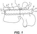
FIG. 1 is a sagittal view of a vertebra with an orthopedic fixation assembly including a pedicle screw received within an expandable bone anchor according to one embodiment; -
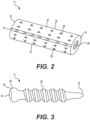
FIG. 2 shows a perspective view of the expandable bone anchor ofFIG. 1 according to one embodiment; -
FIG. 3 shows a side view of the pedicle screw ofFIG. 1 according to one embodiment; -
FIG. 4 is a side view of the expandable bone anchor in an expanded state according to one embodiment; -
FIG. 5 shows a cross-sectional view of the expandable bone anchor in a collapsed state according to one embodiment; -
FIG. 6 is a sagittal view of a vertebra depicting a bone channel or tunnel cut through the pedicle and into the vertebral body; -
FIG. 7 shows alternative types of bone channels or tunnels; -
FIG. 8 shows an axial view of the vertebra with bilateral bone channels through both of the pedicles; -
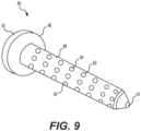
FIG. 9 shows an expandable plug with deployable teeth configured to fill the prepared bone channel according to one embodiment; -
FIG. 10 shows the moveable anchor teeth ejected from the expandable plug ofFIG. 9 according to one embodiment; -
FIG. 11 is a posterior view of a portion of the spine including the bone channels through the pedicles and unused pedicle space around each pedicle screw; -
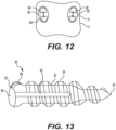
FIG. 12 is a posterior view of a vertebra with an implant expanded to fill the unused pedicle space according to one embodiment; and -
FIG. 13 is an expandable implant with an expandable head and proximal portion according to one embodiment. - Bilateral pedicle screw fixation may be used to treat degenerative disc disease and other spine pathologies. One or more expandable implants may be used to secure the device(s) within the pedicle and/or vertebral body of the vertebra. The expandable implants may include an assembly including an expandable anchor for receiving a pedicle screw, an expandable bone plug with deployable prongs or teeth, an expandable fastener with an expandable head and proximal shaft for receiving an expansion member, or other similar expansion mechanisms. The expandable configuration(s) may allow for unused pedicle space to be filled and utilized. The expandable implants may improve the primary stability of the construct, which may help to reduce the effects of micro motion and facilitate osseointegration of the implant with the surrounding bone. The terms device, fixation device, assembly, and implant may be used interchangeably herein.
- Referring now to
FIG. 1 , an orthopedic fixation assembly, pedicle bone fastener assembly, orimplant 10 according to one embodiment is shown implanted intovertebra 2. The method of fixation may include, for example, accessing the spine from the posterior and inserting theimplant 10 into thepedicle 6 of thevertebra 2. If necessary, bone may be removed from thepedicle 6 and/or thevertebral body 4 in order to facilitate placement of thedevice 10. One ormore pedicle devices 10 may be used alone or in conjunction with a traditional interbody fusion device. Although the method is shown with respect to asingle pedicle 6, it will be appreciated that the other pedicle (not shown) may also receive the same or a similar device. In particular, a pair ofimplants 10 may be implanted bilaterally and angled medially toward one another in thevertebral body 4, but the final location and orientation of thedevices 10 will be selected by a surgeon. It will also be appreciated that the same or similar devices may also be used on adjacent or other levels. - Turning now to
FIGS. 2-5 , thepedicle fixation implant 10 is shown in more detail. Thepedicle implant 10 may include anexpandable bone anchor 12 and apedicle screw 14. As best seen inFIG. 2 , theexpandable bone anchor 12 has a collapsed configuration, thereby allowing theanchor 12 to be inserted through thepedicle 6 and into thevertebral body 4 of thevertebra 2, for example, in a minimally invasive manner. Once inserted in thevertebral body 4, thebone anchor 12 may be expanded into an expanded configuration, as best seen inFIG. 4 , thereby creating a strong press-fit in the bone. Alternatively, theanchor 12 may be placed in thepedicle 6 or cancellous bone only. After thebone anchor 12 is installed, thepedicle screw 14 may be inserted through thepedicle 6 and driven into the expandedbone anchor 12 to complete thefinal assembly 10. Theanchor 12 may be expanded to size, for example, with an instrument and then the pedicle screw may be inserted afterwards. Alternatively, thepedicle screw 14 may expand theanchor 12 during insertion of thepedicle screw 14 into theanchor 12. - The bone implants or components thereof may be comprised of titanium, stainless steel, cobalt chrome, cobalt-chrome-molybdenum, tungsten carbide, carbon composite, plastic or polymer-such as polyetheretherketone (PEEK), polyethylene, ultra-high molecular weight polyethylene (UHMWPE), resorbable polylactic acid (PLA), polyglycolic acid (PGA), combinations or alloys of such materials or any other appropriate material that has sufficient strength to be secured to and hold bone, while also having sufficient biocompatibility to be implanted into a body. Although the above list of materials includes many typical materials out of which implants may be made, it should be understood that implants comprised of any appropriate material are contemplated.
- The
expandable bone anchor 12 is configured to be arranged in a collapsed configuration shown inFIG. 2 and in an expanded configuration shown inFIG. 4 . With further emphasis onFIG. 2 , theexpandable anchor 12 may have a body extending from afirst end 16 to asecond end 18 along a central longitudinal axis. Thefirst end 16 and thesecond end 18 are opposite along the longitudinal axis of the body of theexpandable anchor 12. Thefirst end 16 may be a proximal end and thesecond end 18 may be a distal end configured to be inserted through thepedicle 6 and into thevertebral body 4 of thevertebra 2. Theanchor 12 may have a generally cylindrical outer shape in its collapsed and/or expanded configuration. However, various profile geometries could be utilized in order to increase the press fit force generated during expansion of theanchor 12. - The
anchor 12 may include amulti-component body 20. For example, thebody 20 may include a plurality ofexpandable sections 22 configured to radially expand outward and away from one another. Theexpandable sections 22 may be separated from one another by one ormore expansion joints 24. Theexpandable sections 22 are connected by means of the one ormore expansion joints 24. The expandingjoints 24 allow theanchor 12 to expand and fill theprepared hole 8 through thepedicle 6 and/orvertebral body 4. In one embodiment, as best seen inFIG. 5 , theanchor 12 may be divided into fourexpandable sections 22 or quadrants each adjacent to anexpansion joint 24. In other words anexpansion joint 24 mutually connects two adjacentexpandable sections 22. Although fourexpandable joints 24 are exemplified, theanchor 12 could have various numbers of sections/joints in order to facilitate expansion and fit the desired hole size and shape in thevertebral body 4 and/orpedicle 6. In a version each expanding joint 24 comprises a plurality of expandingelement 24 staggered along the longitudinal direction of the body of theexpandable anchor 12 so as to improve the expansion of the body. In another version each expanding joint 24 extends along the longitudinal direction of the body of theexpandable anchor 12 so as to improve the expansion of the body. - The
anchor sections 22 may be attached together by malleable or flexible material in theexpansion joint 24 that allows theexpandable sections 22 to expand while still maintaining connection to each other. The malleable or flexible material may be fabricated from a polymeric material or other naturally resilient material, such as a shape memory alloy, or other resilient biocompatible material of sufficient strength and durability for expanding and securing theexpandable sections 22. Each expansion joint may include a single expansion element made of flexible material that extends along the longitudinal axis of the body or a plurality of expansion element made of flexible material staggered along the length of the body. Alternatively, theexpansion joints 24 may include a mechanical joint, such as a hinge, spring, or the like. When theexpandable sections 22 are expanded apart, a width of theexpansion joint 24 increases, thereby increasing the overall diameter of theanchor 12. For example, eachexpansion joint 24 may include a plurality of springs or hinges or mechanical joints staggered along the length of the body. - The
anchor 12 may be cannulated and include a throughhole 26 arranged along the central longitudinal axis of theanchor 12. In a version theanchor 12 defines a throughhole 26 of different diameters in the collapsed and in the expanded configuration. The throughhole 26 extends along the longitudinal axis of theanchor 12. Theexpandable sections 22 may form a plurality of segments or arcs surrounding the throughhole 26. The throughhole 26 may extend from theproximal end 16 to the distal 18 or along a portion thereof. The throughhole 26 may have a constant diameter or may vary along the length of theanchor 12. The throughhole 26 may be internally threaded and configured to engage withcorresponding threads 36 along thepedicle screw 14. The diameter of the throughhole 26 may increase as theanchor 12 is expanded outwards. in a version thepedicle screw 14 is configured to be received in the throughhole 26 in its expanded configuration engaging theexpandable sections 22. - The
anchor 12 may include a plurality of serrations, friction enhancing surfaces, ridges, orteeth 28, for example. The serrations orteeth 28 may be configured to grip the bone of thevertebrae 2. The serrations orteeth 28 may extend along the entire length of theanchor 12 or a portion thereof. The outside of theanchor 12 may include a pattern ofteeth 28 in order to increase the bone to implant surface area contact. In this embodiment, theteeth 28 are shown as being pyramidal but the variations in teeth geometry are limitless. It would be ideal to select a tooth geometry that optimizes the interaction with the patient's bone taking into account the bone mineral density in the area where theanchor 12 is expanded. When theanchor 12 is expanded, theteeth 28 are configured to press into the surrounding bone to further stabilize theanchor 12. - With further emphasis on
FIG. 3 , thepedicle screw 14 may have a body extending from afirst end 30 to a second 32 along a central longitudinal axis. Thefirst end 30 of thepedicle screw 14 may be a proximal end and may include arecess 34 configured to receive an instrument for inserting thepedicle screw 14. Thefirst end 30 may have anenlarged head portion 38 or may be otherwise configured (e.g., headless). As best seen inFIG. 1 , when installed, thehead 38 of thepedicle screw 14 may protrude outside thevertebra 2 to receive a tulip or other assembly for attaching a rod or similar construct. Thesecond end 32 may be a distal end configured to be inserted into thepedicle 6 ofvertebra 2 and into the throughhole 26 in theproximal end 16 of theanchor 12. In this manner, the central longitudinal axis of thepedicle screw 14 may be generally aligned with the central longitudinal axis of theexpandable anchor 12. Thesecond end 32 of thepedicle screw 14 may have a distal tip that is blunt, pointed, or otherwise configured to engage bone and/or theanchor 12. - As shown in
FIG. 1 , the length ofexpandable anchor 12 may be shorter than the length of thepedicle screw 14 such that theexpandable anchor 12 is only provided at a distal region of the screw 14 (e.g., within the vertebral body 4). Alternatively, thepedicle screw 14 may be threaded through theexpandable anchor 12 such thatexpandable anchor 12 may be provided at a proximal region of the screw 14 (e.g., within the pedicle 6). Alternatively, theexpandable anchor 12 may have a length similar to the length of the shaft of thescrew 14, thereby allowing for fixation in thevertebral body 4 and thepedicle 6 of thevertebra 2. - The body of the
pedicle screw 14 may include one ormore threads 36 along the entire length of the shaft or a portion thereof. Thethread 36 may have a suitable angle, lead, pitch, etc. to enhance insertion and/or engagement with the bone and/or engaged to theanchor 12. The outer diameter of thepedicle screw 14 may be constant or may vary along its length. For example, thedistal end 32 may have a reduced diameter. Although apedicle screw 14 is exemplified in this embodiment, it will be appreciated that thepedicle screw 14 could be substituted with another fastener, such as a nail or other fixation device. - Turning now to
FIGS. 6-8 , one or more tunnels orchannels 8 may be created through thepedicle 6 and into thevertebral body 4. Thechannel 8 may be created with a bone drill or other suitable instrument. As shown inFIG. 7 , thechannels 8 may have a smooth surface 8A (e.g., with a constant diameter), aridged surface 8B (e.g., with evenly spaced ridges), or arandomized surface 8C. As shown inFIG. 8 , a pair ofbilateral channels 8 may be cut through eachpedicle 6 of thevertebra 2 and into thevertebral body 4. Thebilateral channels 8 may point medially toward one another or along another suitable trajectory selected by the surgeon. - According to one embodiment, the
system 10 may be implanted as follows: (1) The hole orchannel 8 for thebone anchor 12 is prepared by drilling through thepedicle 6 and into thevertebrae 2, for example, along the same trajectory that a normal pedicle screw would be placed. (2) Thebone anchor 12 is fully seated at the end of the previouslyprepared hole 8. (3) Thebone anchor 12 is expanded, thereby creating a strong press fit in the bone. (4) Thepedicle screw 14 is inserted into theprepared hole 8 and driven into the expandedbone anchor 12, thereby securing and anchoring thepedicle screw 14 to the expandedanchor 12. - The expansion of the
anchor 12 may be accomplished through one or more methods. A specialized instrument (not shown) may be inserted into theprepared hole 8 and through theanchor 12 where theanchor 12 is then expanded under force generated from the instrument. This expansion force could be due to threading the instrument through an undersized or tapered thread inside theanchor 12 which causes theexpandable sections 22 to expand radially outward. As an alternative, the instrument tip may expand mechanically or inflate like a balloon similar to balloon deployed stents. In an alternative method, insertion of thepedicle screw 14 into theanchor 12 simultaneously expands theanchor 12 as thepedicle screw 14 is threaded through theanchor 12. - Turning now to
FIGS. 9 and10 , an orthopedic fixation assembly, expandable plug, orimplant 40 according to another embodiment is shown. In this embodiment, individual anchors orteeth 54 are deployable from theanchor body 48 in order to secure theimplant 40 in the bone. Theimplant 40 may have a body extending from afirst end 42 to asecond end 44 along a central longitudinal axis. Thefirst end 42 of theimplant 40 may be a proximal end and thesecond end 44 may be a distal end configured to be inserted through thepedicle 6 and into thevertebral body 4 of thevertebra 2 to fill theprepared bone tunnel 8. Theproximal end 42 may define an enlarged head, flange, orflat head 46 and thedistal end 44 may define a pointed, sharpened, or a blunt end configured to engage bone. - The
implant 40 includes ashank 48 extending along the central longitudinal axis from theflat head 46 to thedistal end 44. Theshank 48 may have a generally cylindrical shape, however, various profile geometries could be utilized in order to increase the fit of theimplant 40 in thebone channel 8. Theimplant 40 is cannulated with acenter channel 50 extending along its length. Thecenter channel 50 is in fluid communication with a plurality of perforations oropenings 52 configured to guide thedeployable teeth 54. - The
deployable teeth 54 may include prongs, spikes, or other anchors configured to secure theimplant 40 in bone. Each anchor ortooth 54 may be elongated with aninner end 56 receivable in thecentral channel 50 and anouter end 58 configured to eject from theopenings 52. Theinner end 56 of eachtooth 54 may have an angled or sloped portion configured to help expand theteeth 54, for example, mechanically, pneumatically, or hydraulically. Theouter end 58 may be pointed, sharpened, blunt, or otherwise configured to engage bone when ejected or expanded. Theteeth 54 may be positioned generally transverse to the central longitudinal axis of theshank 48. In particular, theteeth 54 may be aligned generally perpendicular to the central longitudinal axis of theshank 48. Theteeth 54 may be arranged in a pattern or array around the periphery of theshank 48 or alternatively in a random configuration. The array ofteeth 54 may extend along the entire length of theshank 48 or along a portion thereof. - The
teeth 54 may be ejected pneumatically or with pressurized liquid, bone cement, or the like. Alternatively, theteeth 54 may be ejected mechanically with a piston, drive member, or threaded internal shaft configured to interface with theteeth 54, for example. As shown inFIG. 9 , in the retracted position, theteeth 54 are retracted inside the body of theshank 48. In the deployed position shown inFIG. 10 , theteeth 54 are extended radially outward and away from one another. In this embodiment, the anchor diameter is fixed while theteeth 54 on the anchor surface are deployed from theanchor body 48 in order to secure theimplant 40 in the bone. - Turning now to
FIGS. 11-13 , anexpandable implant 80 is shown according to another embodiment. In this embodiment, the proximal portion of theimplant 80 is configured to expand to fillunused space 72 in thepedicle 6. As shown inFIG. 11 , a posterior view of the spine is shown withbilateral channels 8 cut through thepedicles 6. Cylindrical pedicle screws 70 are inserted into thechannel 8 butunused space 72 exists around thescrews 70. It is believed up to 60% of screw pullout strength may be derived from thespine pedicle 8 itself. Anatomical investigations oflumbar pedicles 6 have shown that thepedicles 6 are ovular in shape which means much of the surrounding bone tissue, especially cortical bone, is not utilized by traditional pedicle screws 70.FIG. 11 represents thegaps 72 and unused bone within thepedicle 6 that is not accessed by cylindrical pedicle screws 70. There is potential to increase the stability of implanted pedicle screws 70 within thepedicle 6 if this bone could be used safely. An increase in stability may reduce the likelihood of screw loosening and construct failure. - In the embodiment shown in
FIGS. 12 and 13 , thepedicle screw 80 is configured to expand in a specific section of thescrew 80 within thepedicle 6. This allows the screw to gain purchase on unused areas of cortical bone which provides maximum strength and stability. Theexpandable implant 80 may have a body extending from afirst end 82 to a second 84 along a central longitudinal axis. Thefirst end 82 of theimplant 80 may be a proximal end and may include arecess 86 configured to receive an instrument for inserting thepedicle screw 80. Thefirst end 82 may have anenlarged head portion 88 or may be otherwise configured (e.g., headless). Thehead 86 may be configured to receive a tulip or other assembly for attaching a rod or similar construct. Thehead 88 and a proximal portion of theimplant 80 may be bifurcated by a slot or slit 90. Theslit 90 may extend along a longitudinal plane. Theslit 90 may extend through a proximal section of the shank 92 (e.g., about half-way through the shank 92). Although asingle slit 90 is exemplified, it will be appreciated that additional slits may be provided to enlarge thehead 88 andproximal shank 92. Thesecond end 84 of theimplant 80 may be a distal end configured to be inserted into thepedicle 6 ofvertebra 2. Thesecond end 84 may have a distal tip that is sharpened, pointed, blunt, or otherwise configured to engage bone. - The
shank 92 of thepedicle screw 80 may include one ormore threads 94 along the entire length of theshank 92 or a portion thereof. Thethread 94 may have a suitable angle, lead, pitch, etc. to enhance insertion and/or engagement with the bone. The outer diameter of thepedicle screw 80 may be constant or may vary along its length. For example, thedistal end 84 may have a reduced diameter. Although anexpandable pedicle screw 84 is exemplified in this embodiment, it will be appreciated that the implant does not necessarily need to be a screw or threaded but can have geometries of various shapes to facilitate the expansion within thespine pedicle 6. - As best seen in
FIG. 12 , theproximal end 82 of theimplant 80 may be expanded to increase purchase in thepedicle 6. In particular, a drive, shaft, wedge, or other implement (not shown) may be introduced into theslit 90 to thereby drive the opposite portions of thehead 88 andshaft 92 apart and away from one another. In this manner, the enlarged or expandedanchor 80 is configured to utilize the previouslyunused pedicle space 72 engaging the cortical bone and thereby increasing the screw pullout strength. It will be appreciated that thepedicle screw implant 80 may be used instead of pedicle screw 14 described previously with theexpandable anchor 12, such that the resulting implant secures both ends in thevertebral body 4 andpedicle 6, respectively. - Inadequate construct stability due to pedicle screw loosening is a major clinical concern. Failure to stabilize the spine may impede the fusion process of the spine segment targeted for fusion. This can lead to a revision surgery which comes with its own array of risk and problems for both the surgeon and patient. The anchor-pedicle screw constructs aim to improve the initial stability of the implant all while dampening the effects of micro motion due to the patient cyclically loading the rod and pedicle screw constructs. This may allow for better osseointegration of the bone around and on the implanted devices which may improve construct stability and facilitate fusion of the spine segment.
- It will be further understood that various changes in the details, materials, and arrangements of the parts which have been described and illustrated in order to explain the nature of this invention may be made by those skilled in the art without departing from the scope of the invention as expressed in the claims. One skilled in the art will appreciate that the embodiments discussed above are non-limiting. It will also be appreciated that one or more features of one embodiment may be partially or fully incorporated into one or more other embodiments described herein.
- The invention could be defined inter alia by the following examples:
- 1. An expandable implant comprising: an expandable anchor having a body with a plurality of expandable sections separated by one or more expansion joints, the anchor includes a central through hole arranged along a central longitudinal axis of the anchor; and a pedicle screw having a head and a shaft, wherein the pedicle screw is receivable in the expandable anchor, and wherein the expandable anchor has a collapsed configuration and an expanded configuration, thereby creating a press-fit in adjacent bone.
- 2. The implant of Example 1, wherein the plurality of expandable sections are configured to radially expand outward and away from one another, thereby increasing an outer diameter of the anchor.
- 3. The implant of Example 1, wherein when the expandable sections are expanded apart, a width of each expansion joint increases to enlarge the anchor.
- 4. The implant of Example 1, wherein the expandable anchor has a cylindrical shape.
- 5. The implant of Example 1, wherein the expandable anchor includes four expandable sections each adjacent to one expansion joint.
- 6. The implant of Example 1, wherein the expansion joints comprise a malleable or flexible material.
- 7. The implant of Example 1, wherein the central through hole is internally threaded and configured to engage with corresponding threads along the shaft of the pedicle screw.
- 8. The implant of Example 1, wherein the anchor includes a plurality of teeth arranged in an array about the periphery of the expandable sections.
- 9. The implant of Example 8, wherein the plurality of teeth are pyramidal in shape.
- 10. The implant of Example 1, wherein a length of the expandable anchor is shorter than a length of the pedicle screw.
- 11. An expandable implant comprising: an enlarged head and a shank extending along a central longitudinal axis, the shank defining a center channel in fluid communication with a plurality of openings; and a plurality of moveable teeth, each tooth having an elongated body with an inner end receivable in the central channel and an outer end configured to eject from the openings in the shank, wherein the teeth have a retracted position and deployed position whereby the teeth extend radially outward from the shank.
- 12. The implant of Example 11, wherein the teeth are positioned perpendicular to the central longitudinal axis of the shank.
- 13. The implant of Example 11, wherein the inner end of each tooth includes an angled portion configured to help expand the teeth.
- 14. The implant of Example 11, wherein the teeth are arranged in a pattern around the periphery of the shank.
- 15. The implant of Example 11, wherein the teeth are ejected with bone cement.
Claims (9)
- An expandable implant comprising:an expandable anchor having a body with a plurality of expandable sections separated by one or more expansion joints, the anchor includes a central through hole arranged along a central longitudinal axis of the anchor; anda pedicle screw having a head and a shaft, wherein the pedicle screw is receivable in the expandable anchor, and wherein the expandable anchor has a collapsed configuration and an expanded configuration, thereby creating a press-fit in adjacent bone.
- The implant of claim 1, wherein the plurality of expandable sections are configured to radially expand outward and away from one another, thereby increasing an outer diameter of the anchor.
- The implant of claim 1 or 2, wherein when the expandable sections are expanded apart, a width of each expansion joint increases to enlarge the anchor.
- The implant of cany one of the preceding claims, wherein the expandable anchor has a cylindrical shape.
- The implant of any one of the preceding claims, wherein the expandable anchor includes four expandable sections each adjacent to one expansion joint.
- The implant of any one of the preceding claims, wherein the expansion joints comprise a malleable or flexible material.
- The implant of any one of the preceding claims, wherein the central through hole is internally threaded and configured to engage with corresponding threads along the shaft of the pedicle screw.
- The implant of any one of the preceding claims, wherein the anchor includes a plurality of teeth arranged in an array about the periphery of the expandable sections.
- The implant of claim 8, wherein the plurality of teeth are pyramidal in shape.
The implant of any one of the preceding claims, wherein a length of the expandable anchor is shorter than a length of the pedicle screw.
Applications Claiming Priority (1)
| Application Number | Priority Date | Filing Date | Title |
|---|---|---|---|
| US17/711,490 US12514618B2 (en) | 2022-04-01 | 2022-04-01 | Expandable bone core for pedicle screw fixation |
Publications (1)
| Publication Number | Publication Date |
|---|---|
| EP4252685A1 true EP4252685A1 (en) | 2023-10-04 |
Family
ID=85781854
Family Applications (1)
| Application Number | Title | Priority Date | Filing Date |
|---|---|---|---|
| EP23164926.0A Withdrawn EP4252685A1 (en) | 2022-04-01 | 2023-03-29 | Expandable bone core for pedicle screw fixation |
Country Status (3)
| Country | Link |
|---|---|
| US (3) | US12514618B2 (en) |
| EP (1) | EP4252685A1 (en) |
| JP (1) | JP7646720B2 (en) |
Families Citing this family (2)
| Publication number | Priority date | Publication date | Assignee | Title |
|---|---|---|---|---|
| US12343055B1 (en) | 2024-08-02 | 2025-07-01 | Institute For Spine & Scoliosis, P.A. | Anchor device for bone implantation during surgical procedures |
| US12690893B1 (en) | 2025-11-11 | 2026-07-28 | Caliber Cla Holdings Llc | Surgical anchor device with captive fastener |
Citations (5)
| Publication number | Priority date | Publication date | Assignee | Title |
|---|---|---|---|---|
| US4474516A (en) * | 1981-05-25 | 1984-10-02 | Hilti Aktiengesellschaft | Anchor bolt assembly |
| US20110144766A1 (en) * | 2008-06-19 | 2011-06-16 | Shreedhar Kale | Allograft Bone Plugs, Systems and Techniques |
| US20170100177A1 (en) * | 2015-10-13 | 2017-04-13 | Kyungpook National University Industry- Academic Cooperation Foundation | Screw fixing apparatus |
| US20180070986A1 (en) * | 2015-03-12 | 2018-03-15 | Spinal Balance, Inc. | Pedicle Reconstruction Device |
| EP3323363A1 (en) * | 2015-07-16 | 2018-05-23 | Kyungpook National University Industry-Academic Cooperation Foundation | Screw anchor assembly |
Family Cites Families (24)
| Publication number | Priority date | Publication date | Assignee | Title |
|---|---|---|---|---|
| US349851A (en) * | 1886-09-28 | Antoine theodoee loeme | ||
| US1057975A (en) * | 1911-05-29 | 1913-04-01 | Henry B Newhall Sr | Bolt-anchor. |
| US1051444A (en) * | 1911-07-18 | 1913-01-28 | Henry B Newhall | Bolt-anchor. |
| US1499072A (en) * | 1923-05-29 | 1924-06-24 | Henry B Newhall | Bolt anchor |
| US6679662B2 (en) * | 1995-10-01 | 2004-01-20 | Fischerwerke Artur Fischer Gmbh & Co. Kg | Expansible plug |
| US6447513B1 (en) * | 1998-10-30 | 2002-09-10 | Ian Ross Griggs | Fixation device |
| DE10134605A1 (en) * | 2001-07-17 | 2003-02-06 | Hilti Ag | expansion anchor |
| US8419780B2 (en) * | 2003-05-08 | 2013-04-16 | Simplicity Orthopedics, Inc. | Apparatus for securing an implantable object to bone |
| CN1909848B (en) * | 2004-01-16 | 2012-05-23 | 扩展整形外科公司 | Fracture Treatment Device |
| DE102004009429A1 (en) * | 2004-02-24 | 2005-09-22 | Biedermann Motech Gmbh | Bone anchoring element |
| US7507241B2 (en) | 2004-04-05 | 2009-03-24 | Expanding Orthopedics Inc. | Expandable bone device |
| US20060095136A1 (en) * | 2004-11-03 | 2006-05-04 | Mcluen Design, Inc. | Bone fusion device |
| US20070260250A1 (en) * | 2006-05-05 | 2007-11-08 | Sdgi Holdings, Inc. | Reinforcement of boney material surrounding a bone implant |
| US8388660B1 (en) * | 2006-08-01 | 2013-03-05 | Samy Abdou | Devices and methods for superior fixation of orthopedic devices onto the vertebral column |
| EP1920722B1 (en) * | 2006-11-10 | 2009-06-24 | BIEDERMANN MOTECH GmbH | Bone anchoring nail |
| US8142479B2 (en) * | 2007-05-01 | 2012-03-27 | Spinal Simplicity Llc | Interspinous process implants having deployable engagement arms |
| GB0710023D0 (en) * | 2007-05-25 | 2007-07-04 | Facilities Council | Graft fixation device |
| US9351778B2 (en) * | 2008-06-20 | 2016-05-31 | Yale University | Porous expansion bolt |
| WO2010105196A1 (en) * | 2009-03-13 | 2010-09-16 | University Of Toledo | Removable anchoring pedicle screw |
| WO2011103217A1 (en) * | 2010-02-16 | 2011-08-25 | Azadeh Farin | Device for enhanced mechanical stabilization |
| EP2637608B1 (en) * | 2010-11-12 | 2016-03-02 | Silver Bullet Therapeutics Inc. | Bone implant and systems that controllably releases silver |
| EP2848221A1 (en) * | 2013-09-11 | 2015-03-18 | Vexim | Helical bone fixation device |
| KR101791004B1 (en) * | 2016-06-08 | 2017-10-27 | 경북대학교 산학협력단 | Screw anchor assembly and a method for using the same to pedicle screw instrumentation |
| US10499969B2 (en) * | 2016-11-07 | 2019-12-10 | Mirus, Llc | Bone fixation screw with deployable anchors |
-
2022
- 2022-04-01 US US17/711,490 patent/US12514618B2/en active Active
- 2022-04-01 US US17/711,555 patent/US12551241B2/en active Active
-
2023
- 2023-03-29 EP EP23164926.0A patent/EP4252685A1/en not_active Withdrawn
- 2023-03-30 JP JP2023054745A patent/JP7646720B2/en active Active
-
2025
- 2025-12-11 US US19/416,567 patent/US20260096837A1/en active Pending
Patent Citations (5)
| Publication number | Priority date | Publication date | Assignee | Title |
|---|---|---|---|---|
| US4474516A (en) * | 1981-05-25 | 1984-10-02 | Hilti Aktiengesellschaft | Anchor bolt assembly |
| US20110144766A1 (en) * | 2008-06-19 | 2011-06-16 | Shreedhar Kale | Allograft Bone Plugs, Systems and Techniques |
| US20180070986A1 (en) * | 2015-03-12 | 2018-03-15 | Spinal Balance, Inc. | Pedicle Reconstruction Device |
| EP3323363A1 (en) * | 2015-07-16 | 2018-05-23 | Kyungpook National University Industry-Academic Cooperation Foundation | Screw anchor assembly |
| US20170100177A1 (en) * | 2015-10-13 | 2017-04-13 | Kyungpook National University Industry- Academic Cooperation Foundation | Screw fixing apparatus |
Also Published As
| Publication number | Publication date |
|---|---|
| JP2023152972A (en) | 2023-10-17 |
| JP7646720B2 (en) | 2025-03-17 |
| US20230310038A1 (en) | 2023-10-05 |
| US12551241B2 (en) | 2026-02-17 |
| US20260096837A1 (en) | 2026-04-09 |
| US12514618B2 (en) | 2026-01-06 |
| US20230310037A1 (en) | 2023-10-05 |
Similar Documents
| Publication | Publication Date | Title |
|---|---|---|
| US12427034B2 (en) | Implants for spinal fixation and or fusion | |
| US20240130866A1 (en) | Compound-arc, splined anchor | |
| US11653962B2 (en) | Apparatus for immobilization and fusion of a synovial joint | |
| US6544265B2 (en) | Apparatus for implantation into bone related applications | |
| US7608077B2 (en) | Method and apparatus for spinal distraction and fusion | |
| US6921403B2 (en) | Method and apparatus for spinal distraction and fusion | |
| EP2593026B1 (en) | Pedicular facet fusion screw with plate | |
| US20260096837A1 (en) | Expandable bone core for pedicle screw fixation | |
| US20100324607A1 (en) | Pedicle screw with expansion anchor sleeve | |
| US9050153B2 (en) | Universally deployable and expandable bone screw anchor | |
| US20070270822A1 (en) | Bone fixation grommet | |
| US8388660B1 (en) | Devices and methods for superior fixation of orthopedic devices onto the vertebral column | |
| US20120283776A1 (en) | Methods and instruments for use in vertebral treatment | |
| MX2011001810A (en) | Dynamic pedicle screw. | |
| JP6864620B2 (en) | Bone screw | |
| US12558135B2 (en) | Osseous anchoring implant with cortical stabilization |
Legal Events
| Date | Code | Title | Description |
|---|---|---|---|
| PUAI | Public reference made under article 153(3) epc to a published international application that has entered the european phase |
Free format text: ORIGINAL CODE: 0009012 |
|
| STAA | Information on the status of an ep patent application or granted ep patent |
Free format text: STATUS: REQUEST FOR EXAMINATION WAS MADE |
|
| 17P | Request for examination filed |
Effective date: 20230329 |
|
| AK | Designated contracting states |
Kind code of ref document: A1 Designated state(s): AL AT BE BG CH CY CZ DE DK EE ES FI FR GB GR HR HU IE IS IT LI LT LU LV MC ME MK MT NL NO PL PT RO RS SE SI SK SM TR |
|
| STAA | Information on the status of an ep patent application or granted ep patent |
Free format text: STATUS: THE APPLICATION IS DEEMED TO BE WITHDRAWN |
|
| 18D | Application deemed to be withdrawn |
Effective date: 20240405 |