EP4252634A1 - Blood pressure measurement module, strap assembly, and wearable device - Google Patents
Blood pressure measurement module, strap assembly, and wearable device Download PDFInfo
- Publication number
- EP4252634A1 EP4252634A1 EP21899721.1A EP21899721A EP4252634A1 EP 4252634 A1 EP4252634 A1 EP 4252634A1 EP 21899721 A EP21899721 A EP 21899721A EP 4252634 A1 EP4252634 A1 EP 4252634A1
- Authority
- EP
- European Patent Office
- Prior art keywords
- blood pressure
- pressure measurement
- measurement module
- light
- strap
- Prior art date
- Legal status (The legal status is an assumption and is not a legal conclusion. Google has not performed a legal analysis and makes no representation as to the accuracy of the status listed.)
- Withdrawn
Links
- 238000009530 blood pressure measurement Methods 0.000 title claims abstract description 123
- 238000004891 communication Methods 0.000 claims abstract description 26
- 230000003287 optical effect Effects 0.000 claims abstract description 26
- 238000005259 measurement Methods 0.000 claims abstract description 25
- 230000004308 accommodation Effects 0.000 claims abstract description 22
- 230000036772 blood pressure Effects 0.000 claims abstract description 20
- 210000000707 wrist Anatomy 0.000 claims description 28
- 230000005540 biological transmission Effects 0.000 claims description 22
- 238000005192 partition Methods 0.000 claims description 17
- 238000009434 installation Methods 0.000 claims description 15
- 238000007789 sealing Methods 0.000 claims description 10
- 230000000149 penetrating effect Effects 0.000 claims description 7
- 239000004033 plastic Substances 0.000 claims description 5
- 229920003023 plastic Polymers 0.000 claims description 5
- 239000004417 polycarbonate Substances 0.000 claims description 4
- 229920000515 polycarbonate Polymers 0.000 claims description 4
- 239000005060 rubber Substances 0.000 claims description 3
- VYPSYNLAJGMNEJ-UHFFFAOYSA-N Silicium dioxide Chemical compound O=[Si]=O VYPSYNLAJGMNEJ-UHFFFAOYSA-N 0.000 claims description 2
- 239000003086 colorant Substances 0.000 claims description 2
- 239000006260 foam Substances 0.000 claims description 2
- 238000002347 injection Methods 0.000 claims description 2
- 239000007924 injection Substances 0.000 claims description 2
- 239000000741 silica gel Substances 0.000 claims description 2
- 229910002027 silica gel Inorganic materials 0.000 claims description 2
- 238000001746 injection moulding Methods 0.000 description 7
- 238000002834 transmittance Methods 0.000 description 7
- 238000000034 method Methods 0.000 description 6
- 230000008569 process Effects 0.000 description 6
- 238000010586 diagram Methods 0.000 description 5
- 230000000694 effects Effects 0.000 description 5
- 239000011521 glass Substances 0.000 description 5
- 239000000919 ceramic Substances 0.000 description 4
- 229910052751 metal Inorganic materials 0.000 description 4
- 239000002184 metal Substances 0.000 description 4
- 238000013461 design Methods 0.000 description 3
- 239000000463 material Substances 0.000 description 3
- 239000010935 stainless steel Substances 0.000 description 3
- 229910001220 stainless steel Inorganic materials 0.000 description 3
- XEEYBQQBJWHFJM-UHFFFAOYSA-N Iron Chemical compound [Fe] XEEYBQQBJWHFJM-UHFFFAOYSA-N 0.000 description 2
- PXHVJJICTQNCMI-UHFFFAOYSA-N Nickel Chemical compound [Ni] PXHVJJICTQNCMI-UHFFFAOYSA-N 0.000 description 2
- 230000000712 assembly Effects 0.000 description 2
- 238000000429 assembly Methods 0.000 description 2
- 210000004204 blood vessel Anatomy 0.000 description 2
- 230000036541 health Effects 0.000 description 2
- 239000007769 metal material Substances 0.000 description 2
- 210000001519 tissue Anatomy 0.000 description 2
- 229910000838 Al alloy Inorganic materials 0.000 description 1
- RYGMFSIKBFXOCR-UHFFFAOYSA-N Copper Chemical compound [Cu] RYGMFSIKBFXOCR-UHFFFAOYSA-N 0.000 description 1
- 206010020772 Hypertension Diseases 0.000 description 1
- WHXSMMKQMYFTQS-UHFFFAOYSA-N Lithium Chemical compound [Li] WHXSMMKQMYFTQS-UHFFFAOYSA-N 0.000 description 1
- 229910000861 Mg alloy Inorganic materials 0.000 description 1
- 239000004676 acrylonitrile butadiene styrene Substances 0.000 description 1
- 239000000853 adhesive Substances 0.000 description 1
- 230000001070 adhesive effect Effects 0.000 description 1
- 210000000577 adipose tissue Anatomy 0.000 description 1
- 229910045601 alloy Inorganic materials 0.000 description 1
- 239000000956 alloy Substances 0.000 description 1
- 238000005452 bending Methods 0.000 description 1
- 230000009286 beneficial effect Effects 0.000 description 1
- 230000003139 buffering effect Effects 0.000 description 1
- 229910017052 cobalt Inorganic materials 0.000 description 1
- 239000010941 cobalt Substances 0.000 description 1
- GUTLYIVDDKVIGB-UHFFFAOYSA-N cobalt atom Chemical compound [Co] GUTLYIVDDKVIGB-UHFFFAOYSA-N 0.000 description 1
- 201000010099 disease Diseases 0.000 description 1
- 208000037265 diseases, disorders, signs and symptoms Diseases 0.000 description 1
- 239000006185 dispersion Substances 0.000 description 1
- 230000001631 hypertensive effect Effects 0.000 description 1
- 230000002452 interceptive effect Effects 0.000 description 1
- 229910052742 iron Inorganic materials 0.000 description 1
- 239000004973 liquid crystal related substance Substances 0.000 description 1
- 229910052744 lithium Inorganic materials 0.000 description 1
- 238000012986 modification Methods 0.000 description 1
- 230000004048 modification Effects 0.000 description 1
- 229910052759 nickel Inorganic materials 0.000 description 1
- 229920001296 polysiloxane Polymers 0.000 description 1
- 238000012545 processing Methods 0.000 description 1
- 230000036387 respiratory rate Effects 0.000 description 1
- 229910052594 sapphire Inorganic materials 0.000 description 1
- 239000010980 sapphire Substances 0.000 description 1
- 230000007704 transition Effects 0.000 description 1
- 239000002023 wood Substances 0.000 description 1
Images




Classifications
-
- A—HUMAN NECESSITIES
- A61—MEDICAL OR VETERINARY SCIENCE; HYGIENE
- A61B—DIAGNOSIS; SURGERY; IDENTIFICATION
- A61B5/00—Measuring for diagnostic purposes; Identification of persons
- A61B5/02—Detecting, measuring or recording for evaluating the cardiovascular system, e.g. pulse, heart rate, blood pressure or blood flow
- A61B5/021—Measuring pressure in heart or blood vessels
- A61B5/02141—Details of apparatus construction, e.g. pump units or housings therefor, cuff pressurising systems, arrangements of fluid conduits or circuits
-
- A—HUMAN NECESSITIES
- A61—MEDICAL OR VETERINARY SCIENCE; HYGIENE
- A61B—DIAGNOSIS; SURGERY; IDENTIFICATION
- A61B5/00—Measuring for diagnostic purposes; Identification of persons
- A61B5/0002—Remote monitoring of patients using telemetry, e.g. transmission of vital signals via a communication network
-
- A—HUMAN NECESSITIES
- A61—MEDICAL OR VETERINARY SCIENCE; HYGIENE
- A61B—DIAGNOSIS; SURGERY; IDENTIFICATION
- A61B5/00—Measuring for diagnostic purposes; Identification of persons
- A61B5/68—Arrangements of detecting, measuring or recording means, e.g. sensors, in relation to patient
- A61B5/6801—Arrangements of detecting, measuring or recording means, e.g. sensors, in relation to patient specially adapted to be attached to or worn on the body surface
- A61B5/6802—Sensor mounted on worn items
- A61B5/681—Wristwatch-type devices
Definitions
- the present disclosure relates to the technical field of wearable devices, and in particular to a blood pressure measurement module, a strap assembly and a wearable device.
- a wearable device such as a smart watch generally include a strap and an electronic device, and the strap is used to wear the electronic device to a user's wrist.
- the electronic device is generally provided with a blood pressure measurement component. After the smart watch is worn on the user's wrist, the electronic device can measure a user's blood pressure to provide health guidance.
- the blood pressure measurement component needs to occupy an internal installation space of the electronic device, which is not conducive to a thinner and lighter design of the electronic device.
- the present disclosure provides a blood pressure measurement module, configured to install on a strap of a wearable device, and the blood pressure measurement module includes:
- the present disclosure provides a strap assembly, configured to connect to an electronic device of a wearable device.
- the strap assembly includes a strap and the above-described blood pressure measurement module, and the strap is connected to the electronic device.
- the preset disclosure provides a wearable device, including an electronic device and the above-described strap assembly, the strap assembly is configured to wear the electronic device on a user's wrist, thereby to make an emitting end of the light emitter face away from a user's wrist.
- a wearable device 10 includes an electronic device 100 and a strap assembly 200, which is installed to the electronic device 100 and can be worn to a user's wrist through the strap assembly 200.
- the electronic device 100 includes a middle frame 110, and electronic components such as a circuit board (not illustrated in figure) and a power supply module (not illustrated in figure) disposed in the middle frame 110.
- the middle frame 110 is provided with an installation cavity, and the electronic components such as the circuit board and the power supply module are disposed in the installation cavity.
- the middle frame 110 can be made of a nonmetallic material such as plastic, rubber, silica gel, wood, ceramics or glass.
- the middle frame 110 can be made of a metallic material such as stainless steel, aluminum alloy or magnesium alloy.
- the middle frame 110 can be a metal injection-molded component, that is, a structural rigidity of the middle frame 110 is ensured by using the metallic material, and an inner surface of a metal body is formed with protrusions, grooves, threaded holes and other structures for assembly and positioning by injection molding.
- the wearable device 10 is a smart watch
- the installation cavity of the middle frame 110 is configured to install electronic components such as a power supply module, a circuit board, a display module 120, a biosensor, etc.
- the circuit board can integrate electronic components such as a processor, a storage unit and a communication module of the wearable device 10, and the power supply module (such as a lithium battery) can supply power to the circuit board, the display module 120 and other electronic components.
- the display module 120 covers the installation cavity and is connected to the middle frame 110, which can be configured to display information and provide an interactive interface for users.
- the display module 120 may further include a display screen and a front cover covering the display screen.
- the display screen may be a liquid crystal display (LCD) screen or an organic light-emitting diode (OLED) screen
- the front cover may be a glass cover or a sapphire cover.
- the front cover is transparent and has relatively high light transmittance, in some embodiments, a light transmittance of the front cover is above 80%.
- the display module 120 may have a touch function, but the touch function is not necessary, and neither is the display module 120.
- the electronic device 100 may include a back cover 130 connected to the middle frame 110, and at least part of a surface of the back cover 130 is attached to the user's wrist after the wearable device 10 is worn on the user's wrist.
- the back cover 130 and the display module 120 are opposite to each other and disposed on two ends of the middle frame 110, and cover two ends of the installation cavity.
- the back cover 130 may be made of glass, ceramic or plastic, and may be provided with a measurement window for measurement of a biosensor such as a heart rate sensor.
- the back cover 130 may be integrally formed with the middle frame 110.
- the electronic device 100 may include more than two kinds of biosensors, which can be configured to detect biological data such as heart rate, respiratory rate or body fat.
- the biosensors can be configured to detect motion states, such as for step counting.
- the wearable device 10 may be a smart bracelet or the like.
- the middle frame 110 is a rectangular frame, and four corners of the rectangle can be processed into arc transition by chamfering process, thus the wearable device 10 has better appearance characteristics.
- the middle frame 110 may have a circular frame shape.
- a side surface of the middle frame 110 (that is, a surface of the middle frame 110 facing away from the installation cavity) may be provided with a matching structure for installing the strap assembly 200, and the strap assembly 200 can form a reliable connection with the middle frame 110 through the matching structure, so as to reliably wear the electronic device 100 to the user's wrist.
- the strap assembly 200 can be conveniently detached from the middle frame 110, thus the user can conveniently replace the strap assembly 200.
- users can purchase various styles of strap assemblies 200, and replace the strap assemblies 200 according to the usage scenarios, so as to improve the convenience of use.
- users can use the more formal strap assembly 200 in formal occasions, and use the casual strap assembly 200 in recreational occasions.
- the strap assembly 200 includes a blood pressure measurement module 210 and two straps 220 (one of the straps is illustrated in FIG. 1 ), and the blood pressure measurement module 210 is installed to one of the straps 220.
- Two opposite ends of the electronic device 100 are respectively provided with card slots 103, and an end of each of the two straps 220 is connected with the electronic device 100, and an end of each of the two straps 220 facing away from the electronic device 100 can be buckled to define an accommodation space, thus the electronic device 100 can be worn on the user's wrist through the two straps 220.
- the strap 220 can be a whole-section structure, an end of the strap 220 is connected to an end of the electronic device 100, and another end of the electronic device 100 can be provided with a snap ring for the strap 220 to pass through, and a free end of the strap 220 can pass through and bypass the snap ring and then be fixed to another position of the strap 220 to form an accommodation space, and a size of the accommodation space is easy to adjust for the convenience of users.
- the blood pressure measurement module 210 includes a housing 211, a measurement assembly 213 and a wireless communication module 214.
- the measurement assembly 213 and the wireless communication module 214 are both arranged in the housing 211.
- the measurement assembly 213 can be configured to measure a blood pressure of the user and transmit the measurement data to the electronic device 100 or an external device such as a mobile phone and a tablet computer through the wireless communication module 214.
- the housing 211 has a rectangular block shape
- the housing 211 is provided with an accommodation cavity 211a
- the housing 211 is configured to connect to the strap 220.
- the housing 211 can be in the shape of a circular block or a racetrack, the racetrack refers to a figure formed by two opposite sides of a rectangle circumscribed by semicircles respectively.
- an end of the housing 211 is provided with a through hole 211b, and an opposite end of the housing 211 is provided with an installation groove 211c configured to connect the strap 220, and the through hole 211b is configured to thread the strap 220.
- the strap 220 may include a first section 221 and a second section 223, an end of the first section 221 is connected to the electronic device 100, an opposite end of the first section 221 is connected to the installation groove 211c of the housing 211, the second section 223 is connected to an opposite end of the housing 211.
- an end of the second section 223 can be connected to the end of the electronic device 100 facing away from the first section 221, and a free end of the second section 223 can pass through the through hole 211b of the housing 211, bypass the end of the housing 211 facing away from the installation groove 211c, and then be fixed to another position of the second section 223.
- the free end of the second section 223 can be provided with a snap, and the second section 223 can be provided with a plurality of snapping holes at intervals along its length direction. After the snap is snapped into one of the snapping holes, the free end of the second section 223 can be fixed, thus the size of the accommodation space for threading the user's wrist can be easily adjusted.
- the second section 223 can be provided with a magnetic piece, and the second section 223 can be provided with a plurality of magnetic attraction fitting pieces along its length direction, and the free end of the second section 223 can be fixed by attracting the magnetic attraction fitting piece and the magnetic piece.
- the magnetic piece can be a magnet
- the magnetic attraction fitting piece can be a magnet
- a magnetic metal piece such as iron, cobalt, nickel and any one of their alloys.
- the wearable device 10 may include another strap 220, and the another strap 220 is connected to the opposite end of the electronic device 100, and the second section 223 can form the accommodation space for threading the user's wrist in cooperation with the another strap 220.
- the housing 211 can be directly connected to the electronic device 100.
- the housing 211 of the blood pressure measurement module 210 can be detachably connected to the middle frame 110 of the electronic device 100.
- an end of the housing 211 is configured to connect to the electronic device 100
- an opposite end of the housing 211 is configured to connect to the strap 220.
- the housing 211 of the blood pressure measurement module 210 and the middle frame 110 of the electronic device 100 can be provided with corresponding matching structures, so as to realize the convenient disassembly of the blood pressure measurement module 210 and the electronic device 100.
- the middle frame 110 of the electronic device 100 can be provided with a telescopic thimble, and the housing 211 of the blood pressure measurement module 210 is provided with a connection hole.
- the thimble can be inserted into the connection hole to realize the assembly of the electronic device 100 and the blood pressure measurement module 210, and the thimble can be withdrawn from the connection hole to detach the blood pressure measurement module 210 from the electronic device 100.
- two opposite ends of the housing 211 may be provided with through holes 211b, and the through holes 211b are configured to thread the strap 220, thus the blood pressure measurement module 210 can be slidably arranged on the strap 220.
- the strap 220 can be threaded through the through hole 211b at an end of the housing 211 and then passed through the through hole 211b at an opposite end of the housing 211, and the blood pressure measurement module 210 can be slidably installed on the strap 220.
- This embodiment can conveniently adjust a position of the blood pressure measurement module 210 on the strap 220, facilitate the assembly of the blood pressure measurement module 210 and the strap 220, and easily realize the detachment of the blood pressure measurement module 210 from the strap 220.
- other structures can be adopted to realize the convenient disassembly and assembly of the blood pressure measurement module 210 and the strap 220, so as to improve the convenience of use.
- the measurement assembly 213 includes a light emitter 2131 and a light receiver 2133, both of which are arranged in the accommodation cavity 211a, and the light receiver 2133 is configured to receive light emitted by the light emitter 2131 and reflected by a human body to the light receiver 2133.
- the light emitter 2131 includes an LED light source.
- the light emitter 2131 emits infrared rays from an emitting end, and the infrared rays pass through the housing 211 and enter the human body. After being absorbed and reflected by human blood vessels and tissues, the infrared rays pass through the housing 211 and enter a receiving end of the light receiver 2133.
- the light source of the light emitter 2131 can adopt other forms, for example, the light emitter 2131 can adopt a light source capable of emitting white light.
- the blood pressure measurement module 210 further includes a circuit board 215 and a battery 217 electrically connected to the circuit board 215. Both the circuit board 215 and the battery 217 are disposed in the accommodation cavity 211a, and both the light emitter 2131 and the light receiver 2133 are electrically connected to the circuit board 215.
- the battery 217 is configured to supply power to the blood pressure measurement module 213 and other electronic components on the circuit board 215.
- the wireless communication module 214 of the blood pressure measurement module 210 is communicably connected to the measurement assembly 213, and the battery 217 can further supply power to the wireless communication module 214.
- the wireless communication module 214 can be configured to perform wireless communication connection with the electronic device 100 of the wearable device 10 to transmit the measurement data of the blood pressure measurement module 210 to the electronic device 100.
- the wireless communication module 214 can directly communicate wirelessly with an external device such as a mobile phone, a tablet computer and another terminal, and transmit the measurement data of the blood pressure measurement module 210 to the external device.
- the wireless communication module 214 may have various forms.
- the wireless communication module 214 may be a Bluetooth communication module, a wireless fidelity (Wi-Fi) communication module, an infrared data association (IrDA) module, a ZigBee communication module, an ultra wideband (UWB) module, a near field communication (NFC) module, etc.
- Wi-Fi wireless fidelity
- IrDA infrared data association
- ZigBee ZigBee communication
- UWB ultra wideband
- NFC near field communication
- the user can detach the strap assembly 200 from the wearable device 10 and attach the blood pressure measurement module 210 to a body part such as a neck, an ear or a fingertip for blood pressure measurement.
- the blood pressure measurement module 210 of this embodiment can transmit blood pressure measurement data to the external device or the electronic device 100 of the wearable device 10 through the wireless communication module 214, thus improving the flexibility of measurement.
- the blood pressure measurement module 210 of this embodiment can obtain more accurate blood pressure measurement values by measuring blood pressure at the neck, the ear or the fingertip, thus the accuracy of the blood pressure measurement can be improved.
- the blood pressure measurement module 210 of the present disclosure is no longer integrated with the electronic device 100 of the wearable device 10, an internal installation space of the electronic device 100 can be saved, which is beneficial to the thinner and lighter design of the electronic device 100. Moreover, since the blood pressure measurement module 210 is no longer integrated into the electronic device 100 of the wearable device 10, the light emitter 2131 and the light receiver 2133 are no longer limited by the installation space of the electronic device 100, thus the blood pressure measurement assembly 213 with stronger performance can be adopted to improve the accuracy of blood pressure measurement. Of course, it can be understood that the blood pressure measurement module 210 of the present disclosure can measure the blood pressure at the wrist of the user, and can also improve the accuracy of the measurement.
- the strap assembly 200 may not be detached from the electronic device 100 during the blood pressure measurement of the user, so as to save the time for disassembling the strap assembly 200 and improve the convenience of use.
- the strap assembly 200 need not be configured to be easily detached from the electronic device 100.
- the battery 217 or the circuit board 215 of the blood pressure measurement module 210 can be defaulted, in some embodiments, a power supply module of the electronic device 100 can be used to supply power to the blood pressure measurement module 210.
- the user can detach the blood pressure measurement module 210 from the strap 220 and attach the blood pressure measurement module 210 to a body part such as a neck, an ear or a fingertip for blood pressure measurement.
- the strap 220 does not need to be detached from the electronic device 100 when the user measures blood pressure through the blood pressure measurement module 210, and the strap 220 does not need to move with the blood pressure measurement module 210, thus the convenience of use can be improved, and the flexibility and accuracy of blood pressure measurement can also be improved.
- the blood pressure measurement module 210 is connected to the strap 220 through the housing 211, and the blood pressure measurement module 210 measures the blood pressure by using the light emitter 2131 and the light receiver 2133. After the blood pressure measurement module 210 is separated from the electronic device 100, the blood pressure measurement module 210 can wirelessly communicate with an external device such as a mobile phone or a tablet computer through the wireless communication module 214, or wirelessly communicate with the electronic device 100 of the wearable device 10 through the wireless communication module 214. The user can remove the wearable device 10 from the wrist and attach the blood pressure measurement module 210 to the neck, the ear, the fingertip and another body part for blood pressure measurement, so as to obtain more accurate blood pressure measurement results. In other words, the above-mentioned blood pressure measurement module 210 is no longer integrated into the electronic device 100 of the wearable device 10, and the blood pressure can be accurately measured without being in good condition, thus the flexibility and accuracy of the blood pressure measurement can be improved.
- the housing 211 includes a bearing member 2113 and a cover plate 2115.
- the cover plate 2115 covers an emitting end of the light emitter 2131 and a receiving end of the light receiver 2133, and the cover plate 2115 encloses with the bearing member 2113 to define the accommodation cavity 211a.
- the light emitter 2131 emits infrared rays from the emitting end
- the infrared rays pass through the housing 211 and enter the human body, are absorbed and reflected by human blood vessels and tissues, and then enter the receiving end of the light receiver 2133 through the cover plate 2115.
- the emitting end of the light emitter 2131 faces away from the user's wrist.
- the cover plate 2115 is located on a side of the housing 211 facing away from the wrist.
- the user can directly attach the fingertip of the other hand to the cover plate 2115 without removing the wearable device 10 from the wrist, so as to measure blood pressure, thereby improving the convenience of use.
- the user can attach the blood pressure measurement module 210 to another part of the body, such as the neck or the ear, to measure blood pressure, which can also improve the convenience of measurement.
- the blood pressure measurement module 210 can measure the blood pressure of the user in real time to improve the convenience of use. Especially, for patients suffering from blood pressure-related diseases or people at risk, such as the elderly or hypertensive patients, the blood pressure measurement module 210 of this embodiment can measure the blood pressure in real time and provide health reminders in time.
- the cover plate 2115 includes a base plate 2115a and a light shielding part 2115b connected to the base plate 2115a, and the light shielding part 2115b defines light transmission areas A1 of the base plate 2115a, and the light transmission areas A1 cover the emitting end of the light emitter 2131 and the receiving end of the light receiver 2133, respectively.
- the light shielding part 2115b forms a racetrack-shaped boundary, and the base plate 2115a is filled in an area surrounded by the racetrack-shaped boundary, thus the light transmission areas A1 of the base plate 2115a are defined by the boundary of the light shielding part 2115b.
- the light shielding part 2115b can be provided with a through hole, and a hole wall of the through hole can be used as a boundary to define the light transmission areas A1 of the base plate 2115a.
- the light transmission areas A1 have a relatively high light transmittance, in some embodiment, the light transmittance of the light transmission area A1 can be above 85%.
- the light shielding part 2115b has a relatively low light transmittance, in some embodiments, the light transmittance of the light shielding part 2115b can be below 40%, so as to shield other electronic components in the blood pressure measurement module 210 by the light shielding part 2115b, and to avoid the interference of ambient light on the light receiver 2133 and influence the accuracy of blood pressure measurement results.
- the base plate 2115a and the light shielding part 2115b are injection molded in two colors.
- the base plate 2115a and the light shielding part 2115b are directly molded by injection molding to form a reliable connection.
- the color of the molded base plate 2115a is different from that of the light shielding part 2115b.
- the base plate 2115a is made of polycarbonate (PC)
- the light shielding part 2115b is made of acrylonitrile butadiene styrene (ABS). After injection molding, the base plate 2115a is transparent and the light shielding part 2115b is black.
- the base plate 2115a is made of PC 141R, and the base plate 2115a after injection molding has the advantages of high transparency and strong fracture resistance.
- the light shielding part 2115b is made of PC, and the light shielding part 2115b after injection molding is black, so as to play a better light shielding effect.
- each light transmission area A1 is closed in a circumferential direction, and the light transmission areas A1 are located in a middle area of the cover plate 2115, thus the blood pressure measurement module 210 has a relatively good appearance effect.
- this structural arrangement can better attach the cover plate 2115 to a body surface, thus the light transmission areas A1 can be reliably attached to the skin, thereby improving the accuracy of measurement.
- a surface of the base plate 2115a facing away from the light shielding part 2115b has a 3D structure (as illustrated in FIG. 3 ), which may include a planar area and curved areas.
- the planar area is located in a middle of the base plate 2115a, and the curved areas extends from edges of the planar area, and two ends of the planar area are provided with the curved areas, thus better appearance characteristics can be obtained.
- the light transmission areas A1 are located in the planar area, and the light transmission areas A1 can be reliably attached to the skin to improve the accuracy of blood pressure measurement.
- one of the light transmission areas A1 is provided with an optical texture structure A2, which covers the emitting end of the light emitter 2131 and is configured to gather light of the light emitter 2131.
- the light gathering function of the optical texture structure A2 can reduce the dissipation of light energy, thus the energy of light can be concentrated in a small area as much as possible, thus avoiding the relatively high irrelevant loss of light after reflection and refraction due to dispersion, and improving the accuracy of blood pressure measurement.
- the optical texture structure A2 and the corresponding portion of the base plate 2115a form a Fresnel lens.
- the Fresnel lens can reduce a thickness of the base plate 2115a where the optical texture structure A2 is located.
- the thickness of the base plate 2115a where the optical texture structure A2 is located is about 0.5 mm.
- a vertical distance between a tip of the optical texture structure A2 and an appearance surface of the base plate 2115a is about 0.5 mm.
- both the light shielding part 2115b and the optical texture structure A2 are located on a side of the base plate 2115a facing towards the light emitter 2131.
- the vertical distance between the tip of the optical texture structure A2 and the surface of the base plate 2115a facing away from the light emitter 2131 is about 0.5 mm.
- the light transmission area A1 where the optical texture structure A2 is located has a better light-gathering effect and a thinner thickness, and is easy to process and shape.
- the light transmission area A1 where the optical texture structure A2 is located can not only obtain better light-gathering effect, but also realize thinner design to reduce the loss of light energy, so as to further improve the accuracy of blood pressure measurement.
- the optical texture structure A2 and the corresponding portion of the base plate 2115a can also form another type of optical lenses, such as a convex lens, so as to obtain a light-gathering effect, which will not be described in detail here.
- the blood pressure measurement module 210 includes a partition member 218, which is arranged at the light transmission areas A1 to partition the emitting end of the light emitter 2131 and the receiving end of the light receiver 2133, so as to avoid light mixing and interference between an emitting light path of the light emitter 2131 and a receiving light path of the light receiver 2133, thereby reducing the accuracy of blood pressure measurement.
- the partition member 218 is made of foam, and has a first hole 218a and a second hole 218b arranged at intervals, a side of the partition member 218 abuts against the cover plate 2115, and an opposite side of the partition member 218 abuts against at least one of the light emitter 2131 and the light receiver 2133, with the first hole 218a corresponding to the emitting end of the light emitter 2131 and the second hole corresponding to the receiving end of the light receiver 2133.
- the partition member 218 may be one of a rubber member, a silicone member, and a plastic member with low light transmittance.
- the partition member 218 can prevent mixed light from being generated between the emitting light path of the light emitter 2131 and the receiving light path of the light receiver 2133, and can also play a buffering role between the measurement assembly 213 and the cover plate 2115, the measurement assembly 213 can reliably abut against the cover plate 2115, thus ensuring the alignment of the light emitter 2131 and the light receiver 2133 with the light transmission areas A1.
- the light shielding part 2115b defines an emitting window and a receiving window which are spaced apart from each other, so as to reduce the interference between the emitting optical path and the receiving optical path.
- This structure combined with the arrangement of the partition member 218, can further prevent the optical path interference between the light emitter 2131 and the light receiver 2133 in a gap between the measurement assembly 213 and the cover plate 2115, thus further improving the accuracy of blood pressure measurement. It can be understood that the partition member 218 can be defaulted.
- the bearing member 2113 includes a frame body 2113a and a bottom cover 2113b, the bottom cover 2113b is disposed on a side of the frame body 2113a facing away from the cover plate 2115, and the bottom cover 2113b, the frame body 2113a and the cover plate 2115 enclose to define the accommodation cavity 211a.
- the bottom cover 2113b may be made of the same material as the frame body 2113a.
- both the bottom cover 2113b and the frame body 2113a may be made of stainless steel, plastic, glass or ceramic.
- the material of the bottom cover 2113b may be different from that of the frame body 2113a.
- the frame body 2113a may be a stainless steel metal injection molding member (MIM), and the bottom cover 2113b may be a ceramic or glass member.
- MIM stainless steel metal injection molding member
- the shape of the bottom cover 2113b can be adapted to the shape of the wrist, thus the blood pressure measurement module 210 can fit the wrist better.
- the side of the bottom cover 2113b facing away from the cover plate 2115 can be machined into an arc surface, the surface of the bottom cover 2113b can better fit the user's wrist and improve the wearing comfort. It can be understood that because the function of the blood pressure measurement module 210 is relatively simple, its external dimension can be set relatively small to improve the external characteristics of the wearable device 10.
- a width of the housing 211 of the blood pressure measurement module 210 can be close to a width of the strap 220, so as to improve the appearance characteristics of the wearable device 10 and avoid greatly influencing the bending of the strap 220 to reduce the wearing comfort.
- the blood pressure measurement module 210 may further include charging terminals 2191 electrically connected to the circuit board 215, and the charging terminals 2191 are exposed at a side of the bottom cover 2113b facing away from the emitting end of the light emitter 2131, and the charging terminals 2191 may be configured to connect an external charger to charge the battery 217 of the blood pressure measurement module 210.
- the charging terminals 2191 may be configured to connect an external charger to charge the battery 217 of the blood pressure measurement module 210.
- the blood pressure measurement module 210 may include magnetic attraction members 2193, which are disposed in the accommodation cavity 211a and fixedly connected with the bottom cover 2113b or the frame body 2113a, and are configured to attract the charger to realize the reliable positioning of the blood pressure measurement module 210 on the charger, thus the charging terminals 2191 can form a reliable electrical connection with the charger.
- the blood pressure measurement module 210 may include sealing rings 2195, and the sealing rings 2195 are respectively sleeved on the charging terminals 2191.
- the bottom cover 2113b is provided with penetrating holes 2113c, and the charging terminal 2191 and the corresponding sealing ring 2195 pass through the corresponding penetrating holes 2113c, and the sealing ring 2195 seals the gap between the charging terminal 2191 and the bottom cover 2113b.
- the sealing ring 2195 and the penetrating hole 2113c and an interference fit between the sealing ring 2195 and the charging terminal 2191, the gap between the charging terminal 2191 and the bottom cover 2113b can be effectively sealed, so as to improve the waterproof and dustproof performance of the blood pressure measurement module 210.
- the charging terminals 2191 can be replaced by a charging coil, so as to wirelessly charge the blood pressure measurement module 210 by using the charging coil, thereby improving the convenience of charging.
- the charging terminals 2191 and the penetrating holes 2113c are not required, the waterproof and dustproof performance of the blood pressure measurement module 210 can be improved.
- the charging coil is spirally wound with copper wire, and the charging coil can be fixedly connected to the bottom cover 2113b with adhesive.
- the charging coil may be formed on the bottom cover 2113b by laser direct structuring (LDS) process to simplify the processing of the charging coil.
- the charging coil may be formed on an inner surface of the bottom cover 2113b or on an outer surface of the bottom cover 2113b, that is, on a side of the bottom cover 2113b facing away from the cover plate 2115.
- the inner surface and the outer surface of the bottom cover 2113b can form charging coils through LDS process to improve the efficiency of wireless charging.
- the charging coil is no longer limited to the planar area.
- the charging coil can be completely arranged in the planar area of the bottom cover 2113b, or completely arranged in the curved area of the bottom cover 2113b, or can extend from the planar area of the bottom cover 2113b to the curved area of the bottom cover 2113b.
- This structural arrangement can make full use of the shape of the housing 211 to improve the structural compactness of the blood pressure measurement module 210, and further reduce the overall size of the blood pressure measurement module 210.
Landscapes
- Health & Medical Sciences (AREA)
- Life Sciences & Earth Sciences (AREA)
- Engineering & Computer Science (AREA)
- Heart & Thoracic Surgery (AREA)
- Public Health (AREA)
- Veterinary Medicine (AREA)
- Biophysics (AREA)
- Pathology (AREA)
- Physics & Mathematics (AREA)
- Biomedical Technology (AREA)
- General Health & Medical Sciences (AREA)
- Medical Informatics (AREA)
- Molecular Biology (AREA)
- Surgery (AREA)
- Animal Behavior & Ethology (AREA)
- Cardiology (AREA)
- Vascular Medicine (AREA)
- Physiology (AREA)
- Computer Networks & Wireless Communication (AREA)
- Measuring Pulse, Heart Rate, Blood Pressure Or Blood Flow (AREA)
Abstract
Description
- The present disclosure relates to the technical field of wearable devices, and in particular to a blood pressure measurement module, a strap assembly and a wearable device.
- A wearable device such as a smart watch generally include a strap and an electronic device, and the strap is used to wear the electronic device to a user's wrist. The electronic device is generally provided with a blood pressure measurement component. After the smart watch is worn on the user's wrist, the electronic device can measure a user's blood pressure to provide health guidance. The blood pressure measurement component needs to occupy an internal installation space of the electronic device, which is not conducive to a thinner and lighter design of the electronic device.
- Based on this, it is necessary to provide a blood pressure measurement module, a strap assembly and a wearable device.
- In an aspect, the present disclosure provides a blood pressure measurement module, configured to install on a strap of a wearable device, and the blood pressure measurement module includes:
- a housing, provided with an accommodation cavity, the housing being configured to connect to the strap;
- a measurement assembly, configured to measure a blood pressure and including: a light emitter and a light receiver, where the light emitter and the light receiver are disposed in the accommodation cavity, and the light receiver is configured to receive light emitted from the light emitter and reflected by a human body; and
- a wireless communication module, communicatively connected to the measurement assembly, where the wireless communication module is configured to perform wireless communication connection with an external device or an electronic device of the wearable device.
- In another aspect, the present disclosure provides a strap assembly, configured to connect to an electronic device of a wearable device. The strap assembly includes a strap and the above-described blood pressure measurement module, and the strap is connected to the electronic device.
- In a still another aspect, the preset disclosure provides a wearable device, including an electronic device and the above-described strap assembly, the strap assembly is configured to wear the electronic device on a user's wrist, thereby to make an emitting end of the light emitter face away from a user's wrist.
- In order to more clearly explain embodiments of the present disclosure or the technical scheme in the related art, the drawings needed to be used in the description of the embodiments or the related art will be briefly introduced below. Apparently, the drawings in the following description are only some of the embodiments of the present disclosure, and other drawings can be obtained according to these drawings without creative work for those skilled in the art.
-
FIG. 1 illustrates a schematic diagram of a wearable device according to an embodiment. -
FIG. 2 illustrates a schematic diagram of an electronic device of a wearable device according to an embodiment. -
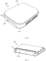
FIG. 3 illustrates a schematic diagram of a blood pressure measurement module of a wearable device according to an embodiment. -
FIG. 4 illustrates a front view of the blood pressure measurement module of the wearable device illustrated inFIG. 3 . -
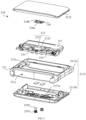
FIG. 5 illustrates an exploded view of the blood pressure measurement module of the wearable device illustrated inFIG. 3 . -
FIG. 6 illustrates a schematic diagram of a wearable device according to another embodiment. -
FIG. 7 illustrates a schematic diagram of a cover plate of a blood pressure measurement module according to an embodiment. -
FIG. 8 illustrates a cross-sectional view of the blood pressure measurement module illustrated inFIG. 4 taken along a line A-A. -
FIG. 9 illustrates an enlarged schematic view at a position B of the blood pressure measurement module illustrated inFIG. 8 . -
FIG. 10 illustrates a rear view of the blood pressure measurement module illustrated inFIG. 3 . -
10, wearable device 100, electronic device 103, card slot 110, middle frame 120, display module 130, back cover 200, strap assembly 210, blood pressure measurement module 211, housing 211a, accommodation cavity 211b, through hole 211c, installation groove 2113, bearing member 2113a, frame body 2113b, bottom cover 2113c, penetrating hole 2115, cover plate 2115a, base plate A1, light transmission area A2, optical texture structure 2115b, light shielding part 213, measurement assembly 2131, light emitter 2133, light receiver 214, wireless communication module 215, circuit board 217, battery 18, partition member 218a, first hole 218b, second hole 2191, charging terminal 2193, magnetic attraction member 2195, sealing ring 220, strap 221, first section 223, second section - In order to facilitate the understanding of the present disclosure, the present disclosure will be described more comprehensively with reference to the relevant drawings. Alternative embodiments of the present disclosure are illustrated in the drawings. However, the present disclosure can be implemented in many different forms and is not limited to the embodiments described herein. On the contrary, these embodiments are provided to make the present disclosure more thorough and comprehensive.
- As illustrated in
FIG. 1 , in some embodiments, awearable device 10 includes anelectronic device 100 and astrap assembly 200, which is installed to theelectronic device 100 and can be worn to a user's wrist through thestrap assembly 200. As illustrated inFIG. 2 , theelectronic device 100 includes amiddle frame 110, and electronic components such as a circuit board (not illustrated in figure) and a power supply module (not illustrated in figure) disposed in themiddle frame 110. Themiddle frame 110 is provided with an installation cavity, and the electronic components such as the circuit board and the power supply module are disposed in the installation cavity. Themiddle frame 110 can be made of a nonmetallic material such as plastic, rubber, silica gel, wood, ceramics or glass. Themiddle frame 110 can be made of a metallic material such as stainless steel, aluminum alloy or magnesium alloy. Themiddle frame 110 can be a metal injection-molded component, that is, a structural rigidity of themiddle frame 110 is ensured by using the metallic material, and an inner surface of a metal body is formed with protrusions, grooves, threaded holes and other structures for assembly and positioning by injection molding. - In some embodiments, the
wearable device 10 is a smart watch, and the installation cavity of themiddle frame 110 is configured to install electronic components such as a power supply module, a circuit board, adisplay module 120, a biosensor, etc. The circuit board can integrate electronic components such as a processor, a storage unit and a communication module of thewearable device 10, and the power supply module (such as a lithium battery) can supply power to the circuit board, thedisplay module 120 and other electronic components. Thedisplay module 120 covers the installation cavity and is connected to themiddle frame 110, which can be configured to display information and provide an interactive interface for users. Thedisplay module 120 may further include a display screen and a front cover covering the display screen. The display screen may be a liquid crystal display (LCD) screen or an organic light-emitting diode (OLED) screen, and the front cover may be a glass cover or a sapphire cover. The front cover is transparent and has relatively high light transmittance, in some embodiments, a light transmittance of the front cover is above 80%. Thedisplay module 120 may have a touch function, but the touch function is not necessary, and neither is thedisplay module 120. - In some embodiment, the
electronic device 100 may include aback cover 130 connected to themiddle frame 110, and at least part of a surface of theback cover 130 is attached to the user's wrist after thewearable device 10 is worn on the user's wrist. In the embodiment where theelectronic device 100 includes thedisplay module 120, theback cover 130 and thedisplay module 120 are opposite to each other and disposed on two ends of themiddle frame 110, and cover two ends of the the installation cavity. Theback cover 130 may be made of glass, ceramic or plastic, and may be provided with a measurement window for measurement of a biosensor such as a heart rate sensor. Of course, in some embodiments, theback cover 130 may be integrally formed with themiddle frame 110. Theelectronic device 100 may include more than two kinds of biosensors, which can be configured to detect biological data such as heart rate, respiratory rate or body fat. In some embodiments, the biosensors can be configured to detect motion states, such as for step counting. In other embodiments, thewearable device 10 may be a smart bracelet or the like. - The
middle frame 110 is a rectangular frame, and four corners of the rectangle can be processed into arc transition by chamfering process, thus thewearable device 10 has better appearance characteristics. In other embodiments, themiddle frame 110 may have a circular frame shape. A side surface of the middle frame 110 (that is, a surface of themiddle frame 110 facing away from the installation cavity) may be provided with a matching structure for installing thestrap assembly 200, and thestrap assembly 200 can form a reliable connection with themiddle frame 110 through the matching structure, so as to reliably wear theelectronic device 100 to the user's wrist. In some embodiments, thestrap assembly 200 can be conveniently detached from themiddle frame 110, thus the user can conveniently replace thestrap assembly 200. In some embodiments, users can purchase various styles ofstrap assemblies 200, and replace thestrap assemblies 200 according to the usage scenarios, so as to improve the convenience of use. In some embodiments, users can use the moreformal strap assembly 200 in formal occasions, and use thecasual strap assembly 200 in recreational occasions. - As illustrated in
FIGS. 1 and2 , in some embodiments, thestrap assembly 200 includes a bloodpressure measurement module 210 and two straps 220 (one of the straps is illustrated inFIG. 1 ), and the bloodpressure measurement module 210 is installed to one of thestraps 220. Two opposite ends of theelectronic device 100 are respectively provided withcard slots 103, and an end of each of the twostraps 220 is connected with theelectronic device 100, and an end of each of the twostraps 220 facing away from theelectronic device 100 can be buckled to define an accommodation space, thus theelectronic device 100 can be worn on the user's wrist through the twostraps 220. In other embodiments, thestrap 220 can be a whole-section structure, an end of thestrap 220 is connected to an end of theelectronic device 100, and another end of theelectronic device 100 can be provided with a snap ring for thestrap 220 to pass through, and a free end of thestrap 220 can pass through and bypass the snap ring and then be fixed to another position of thestrap 220 to form an accommodation space, and a size of the accommodation space is easy to adjust for the convenience of users. - As illustrated in
FIGS. 3 ,4 and5 , the bloodpressure measurement module 210 includes ahousing 211, ameasurement assembly 213 and awireless communication module 214. Themeasurement assembly 213 and thewireless communication module 214 are both arranged in thehousing 211. Themeasurement assembly 213 can be configured to measure a blood pressure of the user and transmit the measurement data to theelectronic device 100 or an external device such as a mobile phone and a tablet computer through thewireless communication module 214. In this embodiment, thehousing 211 has a rectangular block shape, thehousing 211 is provided with anaccommodation cavity 211a, and thehousing 211 is configured to connect to thestrap 220. In other embodiments, thehousing 211 can be in the shape of a circular block or a racetrack, the racetrack refers to a figure formed by two opposite sides of a rectangle circumscribed by semicircles respectively. - As illustrated in
FIG. 4 in conjunction withFIG. 1 , in this embodiment, an end of thehousing 211 is provided with a throughhole 211b, and an opposite end of thehousing 211 is provided with aninstallation groove 211c configured to connect thestrap 220, and the throughhole 211b is configured to thread thestrap 220. Thestrap 220 may include afirst section 221 and asecond section 223, an end of thefirst section 221 is connected to theelectronic device 100, an opposite end of thefirst section 221 is connected to theinstallation groove 211c of thehousing 211, thesecond section 223 is connected to an opposite end of thehousing 211. - In some embodiments, an end of the
second section 223 can be connected to the end of theelectronic device 100 facing away from thefirst section 221, and a free end of thesecond section 223 can pass through the throughhole 211b of thehousing 211, bypass the end of thehousing 211 facing away from theinstallation groove 211c, and then be fixed to another position of thesecond section 223. In some embodiments, the free end of thesecond section 223 can be provided with a snap, and thesecond section 223 can be provided with a plurality of snapping holes at intervals along its length direction. After the snap is snapped into one of the snapping holes, the free end of thesecond section 223 can be fixed, thus the size of the accommodation space for threading the user's wrist can be easily adjusted. Of course, thesecond section 223 can be provided with a magnetic piece, and thesecond section 223 can be provided with a plurality of magnetic attraction fitting pieces along its length direction, and the free end of thesecond section 223 can be fixed by attracting the magnetic attraction fitting piece and the magnetic piece. The magnetic piece can be a magnet, the magnetic attraction fitting piece can be a magnet, or a magnetic metal piece such as iron, cobalt, nickel and any one of their alloys. - Of course, in other embodiments, the
wearable device 10 may include anotherstrap 220, and the anotherstrap 220 is connected to the opposite end of theelectronic device 100, and thesecond section 223 can form the accommodation space for threading the user's wrist in cooperation with the anotherstrap 220. - As illustrated in
FIG. 6 , in other embodiments, thehousing 211 can be directly connected to theelectronic device 100. In some embodiments, thehousing 211 of the bloodpressure measurement module 210 can be detachably connected to themiddle frame 110 of theelectronic device 100. In other words, an end of thehousing 211 is configured to connect to theelectronic device 100, and an opposite end of thehousing 211 is configured to connect to thestrap 220. In this embodiment, thehousing 211 of the bloodpressure measurement module 210 and themiddle frame 110 of theelectronic device 100 can be provided with corresponding matching structures, so as to realize the convenient disassembly of the bloodpressure measurement module 210 and theelectronic device 100. In some embodiments, themiddle frame 110 of theelectronic device 100 can be provided with a telescopic thimble, and thehousing 211 of the bloodpressure measurement module 210 is provided with a connection hole. The thimble can be inserted into the connection hole to realize the assembly of theelectronic device 100 and the bloodpressure measurement module 210, and the thimble can be withdrawn from the connection hole to detach the bloodpressure measurement module 210 from theelectronic device 100. - In other embodiments, two opposite ends of the
housing 211 may be provided with throughholes 211b, and the throughholes 211b are configured to thread thestrap 220, thus the bloodpressure measurement module 210 can be slidably arranged on thestrap 220. In other words, in this embodiment, thestrap 220 can be threaded through the throughhole 211b at an end of thehousing 211 and then passed through the throughhole 211b at an opposite end of thehousing 211, and the bloodpressure measurement module 210 can be slidably installed on thestrap 220. This embodiment can conveniently adjust a position of the bloodpressure measurement module 210 on thestrap 220, facilitate the assembly of the bloodpressure measurement module 210 and thestrap 220, and easily realize the detachment of the bloodpressure measurement module 210 from thestrap 220. In other embodiments, other structures can be adopted to realize the convenient disassembly and assembly of the bloodpressure measurement module 210 and thestrap 220, so as to improve the convenience of use. - As illustrated in
FIG. 5 , themeasurement assembly 213 includes alight emitter 2131 and alight receiver 2133, both of which are arranged in theaccommodation cavity 211a, and thelight receiver 2133 is configured to receive light emitted by thelight emitter 2131 and reflected by a human body to thelight receiver 2133. In this embodiment, thelight emitter 2131 includes an LED light source. Thelight emitter 2131 emits infrared rays from an emitting end, and the infrared rays pass through thehousing 211 and enter the human body. After being absorbed and reflected by human blood vessels and tissues, the infrared rays pass through thehousing 211 and enter a receiving end of thelight receiver 2133. By using photoplethysmographic (PPG), a blood pressure can be calculated. Of course, in other embodiments, the light source of thelight emitter 2131 can adopt other forms, for example, thelight emitter 2131 can adopt a light source capable of emitting white light. - In this embodiment, the blood
pressure measurement module 210 further includes acircuit board 215 and abattery 217 electrically connected to thecircuit board 215. Both thecircuit board 215 and thebattery 217 are disposed in theaccommodation cavity 211a, and both thelight emitter 2131 and thelight receiver 2133 are electrically connected to thecircuit board 215. Thebattery 217 is configured to supply power to the bloodpressure measurement module 213 and other electronic components on thecircuit board 215. Thewireless communication module 214 of the bloodpressure measurement module 210 is communicably connected to themeasurement assembly 213, and thebattery 217 can further supply power to thewireless communication module 214. In some embodiments, thewireless communication module 214 can be configured to perform wireless communication connection with theelectronic device 100 of thewearable device 10 to transmit the measurement data of the bloodpressure measurement module 210 to theelectronic device 100. Of course, in some embodiments, thewireless communication module 214 can directly communicate wirelessly with an external device such as a mobile phone, a tablet computer and another terminal, and transmit the measurement data of the bloodpressure measurement module 210 to the external device. - The
wireless communication module 214 may have various forms. In some embodiments, thewireless communication module 214 may be a Bluetooth communication module, a wireless fidelity (Wi-Fi) communication module, an infrared data association (IrDA) module, a ZigBee communication module, an ultra wideband (UWB) module, a near field communication (NFC) module, etc. - In the embodiment where the
strap assembly 200 is detachably connected to theelectronic device 100, the user can detach thestrap assembly 200 from thewearable device 10 and attach the bloodpressure measurement module 210 to a body part such as a neck, an ear or a fingertip for blood pressure measurement. Compared with the related art in which blood pressure is measured on a wrist and thewearable device 10 is required to wear well, the bloodpressure measurement module 210 of this embodiment can transmit blood pressure measurement data to the external device or theelectronic device 100 of thewearable device 10 through thewireless communication module 214, thus improving the flexibility of measurement. Compared with the related art of measuring blood pressure at the wrist, the bloodpressure measurement module 210 of this embodiment can obtain more accurate blood pressure measurement values by measuring blood pressure at the neck, the ear or the fingertip, thus the accuracy of the blood pressure measurement can be improved. - Of course, it can be understood that since the blood
pressure measurement module 210 of the present disclosure is no longer integrated with theelectronic device 100 of thewearable device 10, an internal installation space of theelectronic device 100 can be saved, which is beneficial to the thinner and lighter design of theelectronic device 100. Moreover, since the bloodpressure measurement module 210 is no longer integrated into theelectronic device 100 of thewearable device 10, thelight emitter 2131 and thelight receiver 2133 are no longer limited by the installation space of theelectronic device 100, thus the bloodpressure measurement assembly 213 with stronger performance can be adopted to improve the accuracy of blood pressure measurement. Of course, it can be understood that the bloodpressure measurement module 210 of the present disclosure can measure the blood pressure at the wrist of the user, and can also improve the accuracy of the measurement. - Of course, it can be understood that the
strap assembly 200 may not be detached from theelectronic device 100 during the blood pressure measurement of the user, so as to save the time for disassembling thestrap assembly 200 and improve the convenience of use. In this embodiment, thestrap assembly 200 need not be configured to be easily detached from theelectronic device 100. In this embodiment, thebattery 217 or thecircuit board 215 of the bloodpressure measurement module 210 can be defaulted, in some embodiments, a power supply module of theelectronic device 100 can be used to supply power to the bloodpressure measurement module 210. - In the embodiment where the
strap 220 is detachably connected to thehousing 211 of the bloodpressure measurement module 210, the user can detach the bloodpressure measurement module 210 from thestrap 220 and attach the bloodpressure measurement module 210 to a body part such as a neck, an ear or a fingertip for blood pressure measurement. In the bloodpressure measurement module 210 of this embodiment, thestrap 220 does not need to be detached from theelectronic device 100 when the user measures blood pressure through the bloodpressure measurement module 210, and thestrap 220 does not need to move with the bloodpressure measurement module 210, thus the convenience of use can be improved, and the flexibility and accuracy of blood pressure measurement can also be improved. - The blood
pressure measurement module 210 is connected to thestrap 220 through thehousing 211, and the bloodpressure measurement module 210 measures the blood pressure by using thelight emitter 2131 and thelight receiver 2133. After the bloodpressure measurement module 210 is separated from theelectronic device 100, the bloodpressure measurement module 210 can wirelessly communicate with an external device such as a mobile phone or a tablet computer through thewireless communication module 214, or wirelessly communicate with theelectronic device 100 of thewearable device 10 through thewireless communication module 214. The user can remove thewearable device 10 from the wrist and attach the bloodpressure measurement module 210 to the neck, the ear, the fingertip and another body part for blood pressure measurement, so as to obtain more accurate blood pressure measurement results. In other words, the above-mentioned bloodpressure measurement module 210 is no longer integrated into theelectronic device 100 of thewearable device 10, and the blood pressure can be accurately measured without being in good condition, thus the flexibility and accuracy of the blood pressure measurement can be improved. - As illustrated in
FIG. 5 , thehousing 211 includes a bearingmember 2113 and acover plate 2115. Thecover plate 2115 covers an emitting end of thelight emitter 2131 and a receiving end of thelight receiver 2133, and thecover plate 2115 encloses with the bearingmember 2113 to define theaccommodation cavity 211a. After thelight emitter 2131 emits infrared rays from the emitting end, the infrared rays pass through thehousing 211 and enter the human body, are absorbed and reflected by human blood vessels and tissues, and then enter the receiving end of thelight receiver 2133 through thecover plate 2115. - In this embodiment, after the
electronic device 100 is worn on the user's wrist, the emitting end of thelight emitter 2131 faces away from the user's wrist. In other words, after theelectronic device 100 is worn on the user's wrist, thecover plate 2115 is located on a side of thehousing 211 facing away from the wrist. In the process of measuring blood pressure, the user can directly attach the fingertip of the other hand to thecover plate 2115 without removing thewearable device 10 from the wrist, so as to measure blood pressure, thereby improving the convenience of use. Of course, in this embodiment, the user can attach the bloodpressure measurement module 210 to another part of the body, such as the neck or the ear, to measure blood pressure, which can also improve the convenience of measurement. - Of course, in other embodiments, after the
electronic device 100 is worn on the user's wrist, the emitting end of the light emitter can face towards the user's wrist, that is, thecover plate 2115 is attached to the user's wrist. In this embodiment, the bloodpressure measurement module 210 can measure the blood pressure of the user in real time to improve the convenience of use. Especially, for patients suffering from blood pressure-related diseases or people at risk, such as the elderly or hypertensive patients, the bloodpressure measurement module 210 of this embodiment can measure the blood pressure in real time and provide health reminders in time. - As illustrated in
FIG. 7 , in this embodiment, thecover plate 2115 includes abase plate 2115a and alight shielding part 2115b connected to thebase plate 2115a, and thelight shielding part 2115b defines light transmission areas A1 of thebase plate 2115a, and the light transmission areas A1 cover the emitting end of thelight emitter 2131 and the receiving end of thelight receiver 2133, respectively. In some embodiments, thelight shielding part 2115b forms a racetrack-shaped boundary, and thebase plate 2115a is filled in an area surrounded by the racetrack-shaped boundary, thus the light transmission areas A1 of thebase plate 2115a are defined by the boundary of thelight shielding part 2115b. In other embodiments, thelight shielding part 2115b can be provided with a through hole, and a hole wall of the through hole can be used as a boundary to define the light transmission areas A1 of thebase plate 2115a. The light transmission areas A1 have a relatively high light transmittance, in some embodiment, the light transmittance of the light transmission area A1 can be above 85%. Thelight shielding part 2115b has a relatively low light transmittance, in some embodiments, the light transmittance of thelight shielding part 2115b can be below 40%, so as to shield other electronic components in the bloodpressure measurement module 210 by thelight shielding part 2115b, and to avoid the interference of ambient light on thelight receiver 2133 and influence the accuracy of blood pressure measurement results. - In this embodiment, the
base plate 2115a and thelight shielding part 2115b are injection molded in two colors. In other words, thebase plate 2115a and thelight shielding part 2115b are directly molded by injection molding to form a reliable connection. The color of the moldedbase plate 2115a is different from that of thelight shielding part 2115b. In some embodiments, thebase plate 2115a is made of polycarbonate (PC), and thelight shielding part 2115b is made of acrylonitrile butadiene styrene (ABS). After injection molding, thebase plate 2115a is transparent and thelight shielding part 2115b is black. In other embodiments, thebase plate 2115a is made of PC 141R, and thebase plate 2115a after injection molding has the advantages of high transparency and strong fracture resistance. Thelight shielding part 2115b is made of PC, and thelight shielding part 2115b after injection molding is black, so as to play a better light shielding effect. - In this embodiment, each light transmission area A1 is closed in a circumferential direction, and the light transmission areas A1 are located in a middle area of the
cover plate 2115, thus the bloodpressure measurement module 210 has a relatively good appearance effect. In the process of measuring blood pressure, this structural arrangement can better attach thecover plate 2115 to a body surface, thus the light transmission areas A1 can be reliably attached to the skin, thereby improving the accuracy of measurement. In some embodiments, a surface of thebase plate 2115a facing away from thelight shielding part 2115b has a 3D structure (as illustrated inFIG. 3 ), which may include a planar area and curved areas. The planar area is located in a middle of thebase plate 2115a, and the curved areas extends from edges of the planar area, and two ends of the planar area are provided with the curved areas, thus better appearance characteristics can be obtained. The light transmission areas A1 are located in the planar area, and the light transmission areas A1 can be reliably attached to the skin to improve the accuracy of blood pressure measurement. - As illustrated in
FIGS. 8 and9 , in this embodiment, one of the light transmission areas A1 is provided with an optical texture structure A2, which covers the emitting end of thelight emitter 2131 and is configured to gather light of thelight emitter 2131. The light gathering function of the optical texture structure A2 can reduce the dissipation of light energy, thus the energy of light can be concentrated in a small area as much as possible, thus avoiding the relatively high irrelevant loss of light after reflection and refraction due to dispersion, and improving the accuracy of blood pressure measurement. - In some embodiments, the optical texture structure A2 and the corresponding portion of the
base plate 2115a form a Fresnel lens. The Fresnel lens can reduce a thickness of thebase plate 2115a where the optical texture structure A2 is located. In some embodiments, the thickness of thebase plate 2115a where the optical texture structure A2 is located is about 0.5 mm. In other words, a vertical distance between a tip of the optical texture structure A2 and an appearance surface of thebase plate 2115a is about 0.5 mm. In some embodiments, both thelight shielding part 2115b and the optical texture structure A2 are located on a side of thebase plate 2115a facing towards thelight emitter 2131. The vertical distance between the tip of the optical texture structure A2 and the surface of thebase plate 2115a facing away from thelight emitter 2131 is about 0.5 mm. In the above embodiment, the light transmission area A1 where the optical texture structure A2 is located has a better light-gathering effect and a thinner thickness, and is easy to process and shape. The light transmission area A1 where the optical texture structure A2 is located can not only obtain better light-gathering effect, but also realize thinner design to reduce the loss of light energy, so as to further improve the accuracy of blood pressure measurement. In other embodiments, the optical texture structure A2 and the corresponding portion of thebase plate 2115a can also form another type of optical lenses, such as a convex lens, so as to obtain a light-gathering effect, which will not be described in detail here. - As illustrated in
FIG. 5 , in this embodiment, the bloodpressure measurement module 210 includes apartition member 218, which is arranged at the light transmission areas A1 to partition the emitting end of thelight emitter 2131 and the receiving end of thelight receiver 2133, so as to avoid light mixing and interference between an emitting light path of thelight emitter 2131 and a receiving light path of thelight receiver 2133, thereby reducing the accuracy of blood pressure measurement. - Specifically, in this embodiment, the
partition member 218 is made of foam, and has afirst hole 218a and asecond hole 218b arranged at intervals, a side of thepartition member 218 abuts against thecover plate 2115, and an opposite side of thepartition member 218 abuts against at least one of thelight emitter 2131 and thelight receiver 2133, with thefirst hole 218a corresponding to the emitting end of thelight emitter 2131 and the second hole corresponding to the receiving end of thelight receiver 2133. In other embodiments, thepartition member 218 may be one of a rubber member, a silicone member, and a plastic member with low light transmittance. - The
partition member 218 can prevent mixed light from being generated between the emitting light path of thelight emitter 2131 and the receiving light path of thelight receiver 2133, and can also play a buffering role between themeasurement assembly 213 and thecover plate 2115, themeasurement assembly 213 can reliably abut against thecover plate 2115, thus ensuring the alignment of thelight emitter 2131 and thelight receiver 2133 with the light transmission areas A1. As illustrated inFIG. 7 , in this embodiment, after injection molding with thebase plate 2115a, thelight shielding part 2115b defines an emitting window and a receiving window which are spaced apart from each other, so as to reduce the interference between the emitting optical path and the receiving optical path. This structure, combined with the arrangement of thepartition member 218, can further prevent the optical path interference between thelight emitter 2131 and thelight receiver 2133 in a gap between themeasurement assembly 213 and thecover plate 2115, thus further improving the accuracy of blood pressure measurement. It can be understood that thepartition member 218 can be defaulted. - As illustrated in
FIG. 5 , in this embodiment, the bearingmember 2113 includes aframe body 2113a and abottom cover 2113b, thebottom cover 2113b is disposed on a side of theframe body 2113a facing away from thecover plate 2115, and thebottom cover 2113b, theframe body 2113a and thecover plate 2115 enclose to define theaccommodation cavity 211a. Thebottom cover 2113b may be made of the same material as theframe body 2113a. In some embodiments, both thebottom cover 2113b and theframe body 2113a may be made of stainless steel, plastic, glass or ceramic. The material of thebottom cover 2113b may be different from that of theframe body 2113a. In some embodiments, theframe body 2113a may be a stainless steel metal injection molding member (MIM), and thebottom cover 2113b may be a ceramic or glass member. - The shape of the
bottom cover 2113b can be adapted to the shape of the wrist, thus the bloodpressure measurement module 210 can fit the wrist better. In some embodiment, the side of thebottom cover 2113b facing away from thecover plate 2115 can be machined into an arc surface, the surface of thebottom cover 2113b can better fit the user's wrist and improve the wearing comfort. It can be understood that because the function of the bloodpressure measurement module 210 is relatively simple, its external dimension can be set relatively small to improve the external characteristics of thewearable device 10. In some embodiments, a width of thehousing 211 of the bloodpressure measurement module 210 can be close to a width of thestrap 220, so as to improve the appearance characteristics of thewearable device 10 and avoid greatly influencing the bending of thestrap 220 to reduce the wearing comfort. - As illustrated in
FIG. 10 , in the embodiment where the bloodpressure measurement module 210 includes thebattery 217, the bloodpressure measurement module 210 may further include chargingterminals 2191 electrically connected to thecircuit board 215, and thecharging terminals 2191 are exposed at a side of thebottom cover 2113b facing away from the emitting end of thelight emitter 2131, and thecharging terminals 2191 may be configured to connect an external charger to charge thebattery 217 of the bloodpressure measurement module 210. As illustrated inFIG. 8 , the bloodpressure measurement module 210 may includemagnetic attraction members 2193, which are disposed in theaccommodation cavity 211a and fixedly connected with thebottom cover 2113b or theframe body 2113a, and are configured to attract the charger to realize the reliable positioning of the bloodpressure measurement module 210 on the charger, thus thecharging terminals 2191 can form a reliable electrical connection with the charger. - In some embodiments, the blood
pressure measurement module 210 may include sealingrings 2195, and the sealing rings 2195 are respectively sleeved on thecharging terminals 2191. Thebottom cover 2113b is provided with penetratingholes 2113c, and the chargingterminal 2191 and thecorresponding sealing ring 2195 pass through the corresponding penetratingholes 2113c, and thesealing ring 2195 seals the gap between the chargingterminal 2191 and thebottom cover 2113b. Through an interference fit between the sealingring 2195 and the penetratinghole 2113c, and an interference fit between the sealingring 2195 and the charging terminal 2191, the gap between the chargingterminal 2191 and thebottom cover 2113b can be effectively sealed, so as to improve the waterproof and dustproof performance of the bloodpressure measurement module 210. - It can be understood that in other embodiments, the
charging terminals 2191 can be replaced by a charging coil, so as to wirelessly charge the bloodpressure measurement module 210 by using the charging coil, thereby improving the convenience of charging. In this embodiment, since thecharging terminals 2191 and the penetratingholes 2113c are not required, the waterproof and dustproof performance of the bloodpressure measurement module 210 can be improved. In some embodiments, the charging coil is spirally wound with copper wire, and the charging coil can be fixedly connected to thebottom cover 2113b with adhesive. - In other embodiments, the charging coil may be formed on the
bottom cover 2113b by laser direct structuring (LDS) process to simplify the processing of the charging coil. In this embodiment, the charging coil may be formed on an inner surface of thebottom cover 2113b or on an outer surface of thebottom cover 2113b, that is, on a side of thebottom cover 2113b facing away from thecover plate 2115. Of course, the inner surface and the outer surface of thebottom cover 2113b can form charging coils through LDS process to improve the efficiency of wireless charging. In this embodiment, the charging coil is no longer limited to the planar area. For example, the charging coil can be completely arranged in the planar area of thebottom cover 2113b, or completely arranged in the curved area of thebottom cover 2113b, or can extend from the planar area of thebottom cover 2113b to the curved area of thebottom cover 2113b. This structural arrangement can make full use of the shape of thehousing 211 to improve the structural compactness of the bloodpressure measurement module 210, and further reduce the overall size of the bloodpressure measurement module 210. - The technical features of the above-mentioned embodiments can be combined arbitrarily. In order to make the description concise, not all possible combinations of the technical features in the above-mentioned embodiments are described. However, as long as there is no contradiction between the combinations of these technical features, they should be considered as the scope recorded in this specification.
- The above-mentioned embodiments only express several implementations of the present disclosure, and their descriptions are more specific and detailed, but they cannot be understood as limiting the scope of the present disclosure. It should be pointed out that for those skilled in the art, without departing from the concept of the present disclosure, several modifications and improvements can be made, which are within the scope of the protection of the present disclosure. Therefore, the scope of protection of the present disclosure should be based on the attached claims.
Claims (23)
- A blood pressure measurement module, configured to install on a strap of a wearable device, wherein the blood pressure measurement module comprises:a housing, provided with an accommodation cavity, the housing being configured to connect to the strap;a measurement assembly, configured to measure a blood pressure and comprising a light emitter and a light receiver, wherein the light emitter and the light receiver are disposed in the accommodation cavity, and the light receiver is configured to receive light emitted by the light emitter and reflected by a human body; anda wireless communication module, communicably connected to the measurement assembly, wherein the wireless communication module is configured to perform wireless communication connection with an external device or an electronic device of the wearable device.
- The blood pressure measurement module according to claim 1, wherein the housing comprises a bearing member and a cover plate, the cover plate covers an emitting end of the light emitter and a receiving end of the light receiver, and the cover plate and the bearing member enclose to define the accommodation cavity.
- The blood pressure measurement module according to claim 2, wherein the cover plate comprises a base plate and a light shielding part connected to the base plate, and the light shielding part defines light transmission areas of the base plate, and the light transmission areas cover the emitting end of the light emitter and the receiving end of the light receiver.
- The blood pressure measurement module according to claim 3, wherein the base plate and the light shielding part are injection molded in two colors.
- The blood pressure measurement module according to claim 3, wherein one of the light transmission areas is provided with an optical texture structure, and the optical texture structure covers the emitting end of the light emitter and is configured to gather light of the light emitter.
- The blood pressure measurement module according to claim 5, wherein the optical texture structure and a corresponding portion of the base plate form a Fresnel lens.
- The blood pressure measurement module according to claim 5, wherein each of the light transmission areas is closed in a circumferential direction.
- The blood pressure measurement module according to claim 5, wherein the light shielding part and the optical texture structure are disposed at a side of the base plate facing towards the light emitter.
- The blood pressure measurement module according to claim 3, wherein the blood pressure measurement module comprises a partition member, and the partition member is disposed at the light transmission areas and configured to partition the emitting end of the light receiver and the receiving end of the light receiver.
- The blood pressure measurement module according to claim 9, wherein the partition member comprises a first hole and a second hole arranged at intervals; a side of the partition member abuts against the cover plate, and another side of the partition member abuts against at least one of the light emitter and the light receiver; and the first hole corresponds to the emitting end of the light emitter and the second hole corresponds to the receiving end of the light receiver.
- The blood pressure measurement module according to claim 10, wherein the partition member is one of a foam, a rubber, a silica gel member and a plastic member; and the base plate is made of polycarbonate.
- The blood pressure measurement module according to any one of claims 2-11, wherein the bearing member comprises a frame body and a bottom cover, the bottom cover is disposed on a side of the frame body facing away from the cover plate, and the bottom cover, the frame body and the cover plate enclose to define the accommodation cavity.
- The blood pressure measurement module according to any one of claims 1-11, wherein the blood pressure measurement module comprises a circuit board and a battery electrically connected to the circuit board, the circuit board and the battery are disposed in the accommodation cavity, and the light emitter and the light receiver are electrically connected to the circuit board.
- The blood pressure measurement module according to claim 13, wherein the blood pressure measurement module comprises charging terminals electrically connected to the circuit board, and the charging terminals are exposed at a side of the housing facing away from the emitting end of the light emitter.
- The blood pressure measurement module according to claim 14, wherein the blood pressure measurement module comprises sealing rings sleeved on the charging terminals correspondingly; the housing is provided with penetrating holes, the charging terminals and the sealing rings penetrate through the penetrating holes correspondingly, and each of the sealing rings seals a gap between the corresponding charging terminal and the housing.
- The blood pressure measurement module according to claim 13, wherein the blood pressure measurement module comprises magnetic attraction members, the magnetic attraction members are disposed in the accommodation cavity and connected to the housing, and the magnetic attraction members are configured to attract a charger.
- The blood pressure measurement module according to claim 13, wherein two opposite ends of the housing are provided with through holes, and the through holes are configured to thread the strap, thereby to make the blood pressure measurement module be slidably arranged on the strap.
- The blood pressure measurement module according to claim 13, wherein an end of the housing is provided with a through hole, and another end of the housing is provided with an installation groove, and the installation groove is configured to connect the strap, and the through hole is configured to thread the strap.
- A strap assembly, configured to connect an electronic device of a wearable device, wherein the strap assembly comprises a strap and the blood pressure measurement module according to any one of claims 1-18, and the strap is connected to the electronic device.
- The strap assembly according to claim 19, wherein the housing is detachably connected to the strap, or the strap assembly is detachably connected to the electronic device.
- A wearable device, comprising an electronic device and the strap assembly according to claim 19 or 20, wherein the strap assembly is configured to wear the electronic device to a user's wrist, thereby to make the emitting end of the light emitter face away from the user's wrist.
- The wearable device according to claim 21, wherein an end of the housing is connected to the electronic device, and another end of the housing is connected to the strap.
- The wearable device according to claim 21, wherein the strap comprises a first section and a second section, an end of the first section is connected to the electronic device, another end of the first section is connected to an end of the housing, and the second section is connected to another end of the housing.
Applications Claiming Priority (2)
| Application Number | Priority Date | Filing Date | Title |
|---|---|---|---|
| CN202022862529.8U CN214712540U (en) | 2020-12-03 | 2020-12-03 | Blood pressure detection module, strap assembly and wearable device |
| PCT/CN2021/123165 WO2022116687A1 (en) | 2020-12-03 | 2021-10-12 | Blood pressure measurement module, strap assembly, and wearable device |
Publications (2)
| Publication Number | Publication Date |
|---|---|
| EP4252634A1 true EP4252634A1 (en) | 2023-10-04 |
| EP4252634A4 EP4252634A4 (en) | 2024-04-24 |
Family
ID=78617687
Family Applications (1)
| Application Number | Title | Priority Date | Filing Date |
|---|---|---|---|
| EP21899721.1A Withdrawn EP4252634A4 (en) | 2020-12-03 | 2021-10-12 | BLOOD PRESSURE MEASUREMENT MODULE, STRAP ASSEMBLY, AND WEARABLE DEVICE |
Country Status (4)
| Country | Link |
|---|---|
| US (1) | US12310702B2 (en) |
| EP (1) | EP4252634A4 (en) |
| CN (1) | CN214712540U (en) |
| WO (1) | WO2022116687A1 (en) |
Families Citing this family (5)
| Publication number | Priority date | Publication date | Assignee | Title |
|---|---|---|---|---|
| EP3975831A4 (en) * | 2019-05-29 | 2023-05-24 | Wear2b Ltd | PORTABLE, NON-INVASIVE, ADJUSTABLE MONITORING DEVICE |
| CN115137132A (en) * | 2021-03-31 | 2022-10-04 | Oppo广东移动通信有限公司 | Functional module, bandage assembly, wearable device and charging method thereof |
| CN116491899A (en) * | 2023-04-18 | 2023-07-28 | Oppo广东移动通信有限公司 | Detection device, electronic device, reminder method |
| CN119138693A (en) * | 2023-06-16 | 2024-12-17 | 荣耀终端有限公司 | Wearable equipment belt body, manufacturing method thereof and wearable equipment |
| CN116991054B (en) * | 2023-09-28 | 2024-03-08 | 荣耀终端有限公司 | Optical device, manufacturing method thereof and wearable equipment |
Family Cites Families (28)
| Publication number | Priority date | Publication date | Assignee | Title |
|---|---|---|---|---|
| EP1721237B1 (en) * | 2004-02-27 | 2012-08-29 | Simon Richard Daniel | Wearable modular interface strap |
| CN107041735B (en) * | 2012-07-17 | 2020-05-19 | 北京超思电子技术有限责任公司 | Wrist strap formula physiological information monitoring devices |
| US10278592B2 (en) * | 2013-12-09 | 2019-05-07 | Samsung Electronics Co., Ltd. | Modular sensor platform |
| WO2015126095A1 (en) * | 2014-02-21 | 2015-08-27 | 삼성전자 주식회사 | Electronic device |
| JP6513708B2 (en) * | 2014-05-23 | 2019-05-15 | サムスン エレクトロニクス カンパニー リミテッド | Adjustable wearable system with modular sensor platform |
| JP6476656B2 (en) * | 2014-08-27 | 2019-03-06 | セイコーエプソン株式会社 | Biological information detection device |
| US9367087B1 (en) * | 2015-03-03 | 2016-06-14 | Pebble Technology Corp. | Securing device for connecting to a display device |
| CN204520654U (en) | 2015-03-03 | 2015-08-05 | 东莞市美光达光学科技有限公司 | An optical sensing device for heart rate and blood pressure monitor |
| KR102384225B1 (en) | 2015-03-06 | 2022-04-07 | 삼성전자주식회사 | System and method for sensing blood pressure |
| US10194809B2 (en) * | 2015-08-24 | 2019-02-05 | Verily Life Sciences Llc | Integrated electronics for photoplethysmography and electrocardiography |
| CN106527106A (en) | 2015-09-14 | 2017-03-22 | 深圳市美达尔前海医疗科技有限公司 | Intelligent watch and blood pressure detection method |
| CN205625904U (en) * | 2016-03-29 | 2016-10-12 | 捷腾光电股份有限公司 | Physiological signal measuring device |
| US10201202B2 (en) * | 2016-07-29 | 2019-02-12 | No Touch L.L.C. | Wearable disease prevention device |
| RU2648029C2 (en) * | 2016-08-10 | 2018-03-21 | Самсунг Электроникс Ко., Лтд. | Device and method of blood pressure measurement |
| US11311238B2 (en) * | 2016-12-14 | 2022-04-26 | Cvr Global, Inc. | Attachable sensing pod comprising a piezoelectric unit |
| CN207837535U (en) | 2017-05-16 | 2018-09-11 | 深圳金亿帝医疗设备股份有限公司 | Pulse pressure conducting structure, portable blood pressure detection module and intelligent wearable device |
| CN206877213U (en) * | 2017-06-05 | 2018-01-12 | 惠州Tcl移动通信有限公司 | Possesses the wearable device of heart rate detecting function |
| US11317814B2 (en) * | 2017-06-27 | 2022-05-03 | Beijing Shunyuan Kaihua Technology Limited | Systems and methods for collecting physiological information of a user |
| EP4470456A3 (en) * | 2017-09-26 | 2025-02-26 | Apple Inc. | Optical sensor subsystem adjacent a cover of an electronic device housing |
| CN110022763A (en) * | 2017-10-09 | 2019-07-16 | 华为技术有限公司 | a wrist watch |
| CN109009055A (en) | 2018-08-08 | 2018-12-18 | 加动健康科技(芜湖)有限公司 | Heart rate measurement unit |
| CN109662699A (en) * | 2018-11-20 | 2019-04-23 | 上海大学 | A kind of two-way physiology signal acquisition device based on photoplethysmography |
| CN109907438A (en) * | 2019-04-10 | 2019-06-21 | 安徽据说牛信息科技有限公司 | A kind of magnetic charging Intelligent bracelet |
| CN211213127U (en) * | 2019-10-11 | 2020-08-11 | 沈宇鸿 | Hypertension monitoring arm ring |
| US11573351B2 (en) * | 2020-03-06 | 2023-02-07 | Apple, Inc. | Optical sensor having a magnetic optical barrier |
| US11240579B2 (en) * | 2020-05-08 | 2022-02-01 | Level 42 Ai | Sensor systems and methods for characterizing health conditions |
| CN213821398U (en) * | 2020-10-22 | 2021-07-30 | Oppo广东移动通信有限公司 | Blood pressure measuring module, watchband for wearable equipment and wearable equipment |
| US11327443B1 (en) * | 2020-10-23 | 2022-05-10 | Anexa Labs Llc | Wearable device for monitoring health metrics |
-
2020
- 2020-12-03 CN CN202022862529.8U patent/CN214712540U/en not_active Expired - Fee Related
-
2021
- 2021-10-12 WO PCT/CN2021/123165 patent/WO2022116687A1/en not_active Ceased
- 2021-10-12 EP EP21899721.1A patent/EP4252634A4/en not_active Withdrawn
-
2023
- 2023-05-30 US US18/325,362 patent/US12310702B2/en active Active
Also Published As
| Publication number | Publication date |
|---|---|
| WO2022116687A1 (en) | 2022-06-09 |
| EP4252634A4 (en) | 2024-04-24 |
| US12310702B2 (en) | 2025-05-27 |
| US20230293030A1 (en) | 2023-09-21 |
| CN214712540U (en) | 2021-11-16 |
Similar Documents
| Publication | Publication Date | Title |
|---|---|---|
| US12310702B2 (en) | Blood pressure measurement module, strap assembly, and wearable device | |
| US20190110744A1 (en) | Interchangeable wearable device | |
| CN104055492A (en) | Electronic Device | |
| US20150342480A1 (en) | Optical pulse-rate sensing | |
| CN106455999A (en) | Optical pulse-rate sensor pillow assembly | |
| CN205547676U (en) | Wearable equipment and intelligent bracelet | |
| CN217566091U (en) | Wearable device | |
| TWM494342U (en) | Smart watch with UV sensor | |
| US20240255897A1 (en) | Wrist-worn apparatus | |
| CN112535482B (en) | Electronics and Wearables | |
| WO2021196878A1 (en) | Electronic device and wearable device | |
| KR20180042472A (en) | Electronic device | |
| WO2021135613A1 (en) | Wearable device | |
| WO2021208567A1 (en) | Wearable device and strap thereof | |
| US20180303416A1 (en) | Wrist-worn type electronic device | |
| CN217852957U (en) | Intelligent watch | |
| CN214846262U (en) | Wearable device | |
| KR20210006947A (en) | Body sensor | |
| CN219146933U (en) | a smart ring | |
| CN215899650U (en) | Physiological signal monitoring devices and intelligent bracelet | |
| CN213665223U (en) | Wearable equipment | |
| CN118787327A (en) | Detection device and electronic equipment | |
| CN209446990U (en) | A kind of smartwatch with bluetooth headset | |
| CN211211707U (en) | Take intelligent bracelet of TWS earphone | |
| CN210248687U (en) | Wrist-worn device |
Legal Events
| Date | Code | Title | Description |
|---|---|---|---|
| STAA | Information on the status of an ep patent application or granted ep patent |
Free format text: STATUS: THE INTERNATIONAL PUBLICATION HAS BEEN MADE |
|
| PUAI | Public reference made under article 153(3) epc to a published international application that has entered the european phase |
Free format text: ORIGINAL CODE: 0009012 |
|
| STAA | Information on the status of an ep patent application or granted ep patent |
Free format text: STATUS: REQUEST FOR EXAMINATION WAS MADE |
|
| 17P | Request for examination filed |
Effective date: 20230628 |
|
| AK | Designated contracting states |
Kind code of ref document: A1 Designated state(s): AL AT BE BG CH CY CZ DE DK EE ES FI FR GB GR HR HU IE IS IT LI LT LU LV MC MK MT NL NO PL PT RO RS SE SI SK SM TR |
|
| DAV | Request for validation of the european patent (deleted) | ||
| DAX | Request for extension of the european patent (deleted) | ||
| A4 | Supplementary search report drawn up and despatched |
Effective date: 20240322 |
|
| RIC1 | Information provided on ipc code assigned before grant |
Ipc: A61B 5/00 20060101ALI20240318BHEP Ipc: A61B 5/021 20060101AFI20240318BHEP |
|
| STAA | Information on the status of an ep patent application or granted ep patent |
Free format text: STATUS: THE APPLICATION IS DEEMED TO BE WITHDRAWN |
|
| 18D | Application deemed to be withdrawn |
Effective date: 20241010 |