EP4252592A2 - Kindertrage - Google Patents
Kindertrage Download PDFInfo
- Publication number
- EP4252592A2 EP4252592A2 EP23193170.0A EP23193170A EP4252592A2 EP 4252592 A2 EP4252592 A2 EP 4252592A2 EP 23193170 A EP23193170 A EP 23193170A EP 4252592 A2 EP4252592 A2 EP 4252592A2
- Authority
- EP
- European Patent Office
- Prior art keywords
- booster seat
- child carrier
- seatback
- upper support
- leg
- Prior art date
- Legal status (The legal status is an assumption and is not a legal conclusion. Google has not performed a legal analysis and makes no representation as to the accuracy of the status listed.)
- Granted
Links
Images




Classifications
-
- A—HUMAN NECESSITIES
- A47—FURNITURE; DOMESTIC ARTICLES OR APPLIANCES; COFFEE MILLS; SPICE MILLS; SUCTION CLEANERS IN GENERAL
- A47D—FURNITURE SPECIALLY ADAPTED FOR CHILDREN
- A47D1/00—Children's chairs
- A47D1/006—Children's chairs dismountable
-
- A—HUMAN NECESSITIES
- A47—FURNITURE; DOMESTIC ARTICLES OR APPLIANCES; COFFEE MILLS; SPICE MILLS; SUCTION CLEANERS IN GENERAL
- A47D—FURNITURE SPECIALLY ADAPTED FOR CHILDREN
- A47D1/00—Children's chairs
- A47D1/002—Children's chairs adjustable
-
- A—HUMAN NECESSITIES
- A47—FURNITURE; DOMESTIC ARTICLES OR APPLIANCES; COFFEE MILLS; SPICE MILLS; SUCTION CLEANERS IN GENERAL
- A47D—FURNITURE SPECIALLY ADAPTED FOR CHILDREN
- A47D1/00—Children's chairs
- A47D1/002—Children's chairs adjustable
- A47D1/004—Children's chairs adjustable in height
-
- A—HUMAN NECESSITIES
- A47—FURNITURE; DOMESTIC ARTICLES OR APPLIANCES; COFFEE MILLS; SPICE MILLS; SUCTION CLEANERS IN GENERAL
- A47D—FURNITURE SPECIALLY ADAPTED FOR CHILDREN
- A47D1/00—Children's chairs
- A47D1/008—Children's chairs with trays
-
- A—HUMAN NECESSITIES
- A47—FURNITURE; DOMESTIC ARTICLES OR APPLIANCES; COFFEE MILLS; SPICE MILLS; SUCTION CLEANERS IN GENERAL
- A47D—FURNITURE SPECIALLY ADAPTED FOR CHILDREN
- A47D1/00—Children's chairs
- A47D1/008—Children's chairs with trays
- A47D1/0083—Children's chairs with trays movable to inoperative position
-
- A—HUMAN NECESSITIES
- A47—FURNITURE; DOMESTIC ARTICLES OR APPLIANCES; COFFEE MILLS; SPICE MILLS; SUCTION CLEANERS IN GENERAL
- A47D—FURNITURE SPECIALLY ADAPTED FOR CHILDREN
- A47D1/00—Children's chairs
- A47D1/008—Children's chairs with trays
- A47D1/0085—Children's chairs with trays removable
-
- A—HUMAN NECESSITIES
- A47—FURNITURE; DOMESTIC ARTICLES OR APPLIANCES; COFFEE MILLS; SPICE MILLS; SUCTION CLEANERS IN GENERAL
- A47D—FURNITURE SPECIALLY ADAPTED FOR CHILDREN
- A47D1/00—Children's chairs
- A47D1/04—Children's chairs convertible from a high chair to a low one, e.g. by reversing
-
- A—HUMAN NECESSITIES
- A47—FURNITURE; DOMESTIC ARTICLES OR APPLIANCES; COFFEE MILLS; SPICE MILLS; SUCTION CLEANERS IN GENERAL
- A47D—FURNITURE SPECIALLY ADAPTED FOR CHILDREN
- A47D1/00—Children's chairs
- A47D1/10—Children's chairs capable of being suspended from, or attached to, tables or other articles
Definitions
- the present invention relates to child carriers according to the pre-characterizing clauses of claim 1.
- a child carrier is one of the consumer goods.
- various types of child carriers available in the market, such as a child high chair or a child booster seat, and designed for accommodating children with different ages.
- a caregiver has to choose a right child carrier according to a child's age.
- such child carriers have complex structure and are not user-friendly enough. Therefore, there is a need to provide an improved child carrier which can be switched between with multiple using modes easily for accommodating children with different ages and/or in different activities.
- the present invention aims at providing a child carrier which has simple structure and can be switched between with multiple using modes easily.
- the claimed child carrier includes a booster seat and a leg assembly.
- the leg assembly is detachably installed on the booster seat.
- the leg assembly includes at least one upper support and at least one lower support.
- the at least one upper support is detachably installed on the booster seat.
- the at least one lower support is detachably installed on the at least one upper support.
- the child carrier is in a high chair mode when the at least one lower support and the at least one upper support are respectively installed on the at least one upper support and the booster seat to connect the leg assembly to the booster seat, the child carrier is in a youth chair mode when the at least one upper support is installed on the booster seat and the at least one lower support is detached from the at least one upper support, and the child carrier is in a booster mode when the at least one upper support is detached from the booster seat to separate the leg assembly from the booster seat.
- the at least one lower support includes at least one first segment and at least one second segment detachably installed on the at least one first segment.
- the leg assembly further includes at least one wheel rotatably disposed the at least one second segment.
- the at least one second segment includes two second segments, and the two second segments are connected to each other to cooperatively form a U-shaped structure.
- the child carrier further includes a releasing module for allowing or restraining at least one of movement of the at least one second segment relative to the at least one first segment, movement of the at least one lower support relative to the at least one upper support and movement of the at least one upper support relative to the booster seat.
- the child carrier further includes a leg rest detachably installed on the at least one upper support and a leg rest releasing assembly for allowing or restraining movement of the leg rest relative to the at least one upper support.
- the child carrier further includes a tray detachably installed on the booster seat and a tray releasing assembly for allowing or restraining movement of the tray relative to the booster seat.
- the child carrier further includes at least one guiding portion, and the at least one guiding portion is for guiding movement of the at least one lower support relative to the at least one upper support or movement of the at least one upper support relative to the booster seat.
- the child carrier further includes a seatback detachably installed on the booster seat.
- the seatback is rotatable relative to the booster seat.
- the seatback includes at least one pivoting protrusion and at least one retaining rib. At least one first slot and at least one second slot communicated with the at least one first slot are formed on the booster seat.
- the at least one pivoting protrusion and the at least one retaining rib are accommodated in the at least one first slot when the seatback is located at an unused position relative to the booster seat, and the at least one pivoting protrusion and at least a portion of the at least one retaining rib are respectively accommodated in the at least one first slot and the at least one second slot when the seatback is located at a used position relative to the booster seat.
- the at least one pivoting protrusion is a cylinder-shaped structure.
- the at least one retaining rib is an arc-shaped structure.
- the child carrier further includes a seatback releasing assembly for allowing or restraining a rotary movement of the seatback relative to the booster seat.
- the child carrier further includes a seatback restraining assembly for allowing or restraining separation of the seatback and the booster seat.
- the booster seat is a one-piece molded structure.
- the claimed child carrier includes a booster seat and a leg assembly.
- the booster seat is a one-piece molded structure.
- the leg assembly is detachably installed on the booster seat.
- the leg assembly includes at least one upper support and at least one lower support.
- the at least one upper support is detachably installed on the booster seat.
- the at least one lower support is detachably installed on the at least one upper support.
- the child carrier is in a high chair mode when the at least one lower support and the at least one upper support are respectively installed on the at least one upper support and the booster seat to connect the leg assembly to the booster seat, the child carrier is in a youth chair mode when the at least one upper support is installed on the booster seat and the at least one lower support is detached from the at least one upper support, and the child carrier is in a booster mode when the at least one upper support is detached from the booster seat to separate the leg assembly from the booster seat.
- the present invention allows a caregiver to switch the child carrier among the high chair mode, the youth chair mode and the booster mode by detaching the lower support only or detaching the upper supports together with the lower supports, so as to position the booster seat at different desired heights.
- the present invention further allows the caregiver to install or remove at least one of the seatback, the tray and the leg rest to provide different features to satisfy the child's needs no matter when the child carrier is in the high chair mode, the youth chair mode or the booster mode. Therefore, the present invention is not only user-friendly but also flexible in use.
- FIG. 1 is a schematic diagram of a child carrier 1 in a high chair mode according to an embodiment of the present invention.
- FIG. 2 to FIG. 4 are schematic diagrams of the child carrier 1 in a youth chair mode with different features according to the embodiment of the present invention.
- FIG. 5 is a schematic diagram of the child carrier 1 in a booster mode according to the embodiment of the present invention.
- FIG. 6 is an exploded diagram of the child carrier 1 according to the embodiment of the present invention.
- the child carrier 1 includes a booster seat 11, a leg assembly 12, a seatback 13, a tray 14 and a leg rest 15.
- the booster seat 11 is for accommodating a child.
- the leg assembly 12 is detachably installed on the booster seat 11 for supporting the booster seat 11.
- the leg assembly 12 includes four upper supports 121 and four lower supports 122. Each upper support 121 is detachably installed on the booster seat 11. Each lower support 122 is detachably installed on the corresponding upper support 121.
- the seatback 13 is detachably installed on the booster seat 11 and rotatable relative to the booster seat 11 for supporting the child's back.
- the tray 14 is detachably installed on the booster seat 11 for supporting the child's goods, such as food and beverages.
- the leg rest 15 is detachably installed on the leg assembly 12 for supporting the child's legs.
- the booster seat 11 can be a one-piece molded structure for implementing a goal of simplicity for both a manufacturer and a caregiver while still providing adequate strength and accommodating ergonomic requirements.
- the four upper supports 121 and the four lower supports 122 are separated structures.
- the present invention is not limited thereto.
- the present invention allows the caregiver to switch the child carrier 1 among the high chair mode, the youth chair mode and the booster mode by detaching the four lower supports 122 only or detaching the four upper supports 121 together with the four lower supports 122, so as to position the booster seat 11 at different desired heights.
- the present invention further allows the caregiver to attach or remove at least one of the seatback 13, the tray 14 and the leg rest 15 to provide different features to satisfy the child's needs no matter when the child carrier 1 is in the high chair mode, the youth chair mode or the booster mode. Therefore, the present invention is not only user-friendly but also flexible in use.
- the four lower supports 122 and the four upper supports 121 can be respectively installed on the four upper supports 121 and the booster seat 11 to connect the leg assembly 12 to the booster seat 11, i.e., each lower support 122 and the corresponding upper support 121 are joined together, and each upper support 121 and the booster seat 11 are joined together.
- the seatback 13 and the tray 14 can be installed on the booster seat 11, and the leg rest 15 can be installed on the two front upper supports 121. In this using mode, the caregiver can feed the child at a higher position.
- the four upper supports 121 can be installed on the booster seat 11, and the four lower supports 122 can respectively detached from the four upper supports 121. Furthermore, the seatback 13 and the tray 14 can be detached from the booster seat 11, and the leg rest 15 can be detached from the two front upper supports 121. In this using mode, the child can sit at a lower position without the leg rest 15.
- the four upper supports 121 can be installed on the booster seat 11, and the four lower supports 122 can respectively detached from the four upper supports 121. Furthermore, the seatback 13 and the tray 14 can be installed on the booster seat 11, and the leg rest 15 can be installed on the two front upper supports 121. In this using mode, the caregiver can feed the child at a lower position.
- the four upper supports 121 can be installed on the booster seat 11, and the four lower supports 122 can respectively detached from the four upper supports 121. Furthermore, the seatback 13 and the tray 14 can be detached from the booster seat 11, and the leg rest 15 can be installed on the two front upper supports 121. In this using mode, the child can sit at a lower position with the leg rest 15.
- the four upper supports 121 can be detached from the booster seat 11 to separate the leg assembly 12 from the booster seat 11. Furthermore, the seatback 13 and the tray 14 can be detached from the booster seat 11. In this using mode, the child carrier can be installed on an adult chair, and the child can sit on the booster seat 11 without the leg assembly 12.
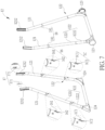
- FIG. 7 is a diagram of the leg assembly 12 according to the embodiment of the present invention.
- each lower support 122 includes a first segment 1221 and a second segment 1222.
- the second segment 1222 is detachably installed on the first segment 1221.
- the two front second segments 1222 are connected to each other to form a U-shaped structure, and the two rear second segments 1222 are connected to each other to form another U-shaped structure.
- the leg assembly 12 can include two wheels 123 and two stands 124.
- FIG. 12 is a schematic diagram of a child carrier 1' in a high chair mode according to another embodiment of the present invention.
- the child carrier 1' includes two lower supports 122'.
- Each lower support 122' can be an integral structure, and there is no stand or wheel disposed on the lower support 122'.
- the child carrier 1 further includes a releasing module.
- the releasing module includes a support releasing assembly 16 for allowing or restraining movement of the corresponding lower support 122 relative the corresponding upper support 121 and a segment releasing assembly 1C for allowing or restraining movement of the corresponding second segment 1222 relative to the corresponding first segment 1221.
- the support releasing assembly 16 includes four support engaging components 161, four support engaging slot structures 162, and four support resilient components, which are not shown in the figures.
- the four support engaging components 161 are respectively movably disposed on the four upper supports 121.
- the four support engaging slot structures 162 are respectively formed on the four lower supports 122.
- the four support resilient components biases the four support engaging components 161 to engage with the four support engaging slot structures 162 respectively.
- the segment releasing assembly 1C includes four segment engaging components 1C1, four segment engaging slot structures 1C2, and four segment resilient components, which are not shown in the figures.
- the four segment engaging components 1C1 are respectively movably disposed on the four first segments 1221.
- the four segment engaging slot structures 1C2 are respectively formed on the four second segments 1222.
- the four segment resilient components biases the four segment engaging components 1C1 to engage with the four segment engaging slot structures 1C2 respectively.
- At least one first guiding portion 1211 is formed on a lower end of each upper support 121.
- At least one second guiding portion which is not shown in the figures, is formed on an upper end of each lower support 122.
- the first guiding portion 1211 can cooperate with the second guiding portion to guide the movement of the lower support 122 relative to the upper support 121 to ensure the lower support 122 to be installed on the upper support 121 properly.
- the lower support 122 includes a similar mechanism to guide the movement of the second segment 1222 relative to the first segment 1221. Detailed description is omitted herein for simplicity.
- the four support engaging components 161 can be pressed to move inwardly to resiliently deform the four support resilient components, so that the four upper supports 121 can be inserted into the four lower supports 122 without any interference.
- the four resiliently deformed support resilient components can drive the four support engaging components 161 to engage with the four support engaging slot structures 162 respectively, so that the four lower supports 122 can respectively engage with the four upper supports 121 by engagement of the four support engaging components 161 and the four support engaging slot structures 162.
- the four support engaging components 161 can be pressed to move inwardly to respectively disengage from the four support engaging slot structures 162, so that the four upper supports 121 can be withdrawn from the four lower supports 122 without any interference.
- each support engaging component 161 can be pressed by the corresponding lower support 122 during insertion of the corresponding upper support 121 into the corresponding lower support 122.
- the caregiver does not have to press the support engaging component 161 manually during the insertion of the upper support 121 into the lower support 122, which facilitates the insertion of the upper support 121 into the lower support 122.
- the support resilient component can preferably be an elastic spring or torsional spring.
- the present invention is not limited thereto.
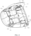
- FIG. 8 is a partial internal structural diagram of the booster seat 11 according to the embodiment of the present invention.
- the releasing module further includes a leg releasing assembly 17 for allowing or restraining movement of the leg assembly 12 relative the booster seat 11.
- the leg releasing assembly 17 includes four leg engaging components 171, four leg engaging slot structures 172, and four leg resilient components, which are not shown in the figures.
- the four leg engaging components 171 are respectively movably disposed on the four upper supports 121.
- the four leg engaging slot structures 172 are respectively formed on four sockets 111 located on four corners of the booster seat 11.
- the four leg resilient components bias the four leg engaging components 171 to engage with the four leg engaging slot structures 172 respectively.
- At least one third guiding portion 1212 is formed on an upper end of each upper support 121.
- At least one fourth guiding portion 1111 is formed inside each socket 111.
- the third guiding portion 1212 can cooperate with the fourth guiding portion 1111 to guide the movement of the upper support 121 relative to the booster seat 11 to ensure the upper support 121 to be installed into the socket 111 properly.
- the four leg engaging components 171 can be pressed to move inwardly to resiliently deform the four leg resilient components, so that the four upper supports 121 can be inserted into the four sockets 111 without any interference.
- the four resiliently deformed leg resilient components can drive the four leg engaging components 171 to engage with the four leg engaging slot structures 172 respectively, so that the four upper supports 121 can engage with the booster seat 11 by engagement of the four leg engaging components 171 and the four leg engaging slot structures 172.
- the four leg engaging components 171 can be pressed to move inwardly to respectively disengage from the four leg engaging slot structures 172, so that the four upper supports 121 can be withdrawn from the four sockets 111 without any interference.
- each leg engaging component 171 can be pressed by the corresponding socket 111 during insertion of the corresponding upper support 121 into the booster seat 11.
- the caregiver does not have to press the leg engaging component 171 manually during the insertion of the upper support 121 into the booster seat 11, which facilitates the insertion of the upper support 121 into the booster seat 11.
- leg resilient component can preferably be an elastic spring or torsional spring.
- the present invention is not limited thereto.
- the child carrier 1 further includes a leg rest releasing assembly 18 for allowing or restraining movement of the leg rest 15 relative to the two front upper supports 121.
- the leg rest releasing assembly 18 includes two leg rest engaging components 181, two leg rest engaging slot structures, which are not shown in the figures, and two leg rest resilient components, which are not shown in the figures.
- the two leg rest engaging components 181 are respectively movably disposed on the two front upper supports 121.
- the two leg rest engaging slot structures are respectively formed on two lateral sides of the leg rest 15.
- the two leg rest resilient components bias the two leg rest engaging components 181 to engage with the two leg rest engaging slot structures respectively.
- the two leg rest engaging components 181 can be pressed to move inwardly to resiliently deform the two leg resilient components, so that the leg rest 15 can be sleeved on the two front upper supports 121 without any interference.
- the two resiliently deformed leg rest resilient components can drive the two leg rest engaging components 181 to engage with the two leg lest engaging slot structures respectively, so that the leg rest 15 can engage with the two front upper supports 121 by engagement of the two leg rest engaging components 181 and the two leg rest engaging slot structures.
- the two leg rest engaging components 181 can be pressed to move inwardly to respectively disengage from the two leg rest engaging slot structures, so that the leg rest 15 can be removed from the two front upper supports 121 without any interference.
- each leg rest engaging component 181 can be pressed by the leg rest 15 during installation of the leg rest 15 onto the two front upper supports 121.
- the caregiver does not have to press the leg rest engaging component 181 manually during the installation of the leg rest 15 onto the two front upper supports 121, which facilitates the installation of the leg rest 15 onto the two front upper supports 121.
- leg rest resilient component can preferably be an elastic spring or torsional spring.
- the present invention is not limited thereto.
- the child carrier 1 further includes a tray releasing assembly 19 for allowing or restraining movement of the tray 14 and the booster seat 11.
- the tray releasing assembly 19 includes two tray engaging components 191, a plurality of tray engaging slot structures 192, a tray resilient component, which is not shown in the figures, and a tray driving component 193.
- the two tray engaging components 191 are respectively movably disposed on two lateral sides of the tray 14.
- the plurality of tray engaging slot structures 192 are formed on two lateral sides of the booster seat 11.
- the tray driving component 193 is movably disposed on a front side of the tray 14 for driving the two tray engaging components 191 to respectively engage with or disengage from the two tray engaging slot structures 192.
- the tray resilient component biases the tray driving component 193 to drive the two tray engaging components 191 to respectively engage with the two tray engaging slot structures 192.
- the tray driving component 193 can be operated to drive the two tray engaging components 191 to move to allow installation of the tray 14 without any interference.
- the tray driving component 193 can be released, so that the resiliently deformed tray resilient component can drive the tray driving component 193 to recover to drive the two tray engaging components 191 to respectively engage with the two tray engaging slot structures 192, so that the tray 14 can engage with the booster seat 11 by engagement of the two tray engaging components 191 and the two corresponding tray engaging slot structures 192.
- the tray driving component 193 can be operated to drive the two tray engaging components 191 to disengage from the two corresponding tray engaging slot structures 192 for allowing the movement of the tray 14 relative to the booster seat 11.
- the tray driving component 193 can be released to engage the two tray engaging components 191 with the two corresponding tray engaging slot structures 192 to position the tray 14.
- the tray driving component 193 can be operated to drive the two tray engaging components 191 to disengage from the two tray engaging slot structures 192, so that the tray 14 can be removed from the booster seat 11 without any interference.
- the tray resilient component can preferably be an elastic spring or torsional spring.
- the present invention is not limited thereto.
- FIG. 9 is a diagram of the seatback 13 according to the embodiment of the present invention.
- FIG. 10 is a partial diagram of the child carrier 1 as the seatback 13 has not been installed on the booster seat 11 yet according to the embodiment of the present invention.
- FIG. 11 is a partial diagram of the child carrier 1 as the seatback 13 is located at a used position according to the embodiment of the present invention.
- the seatback 13 includes two pivoting protrusions 131 and two retaining ribs 132 at two lateral sides.
- a first slot 112 and a second slot 113 communicated with the first slot 112 are formed on each lateral side of the booster seat 11.
- Each first slot 112 is open toward an outer periphery of the booster seat 11, and each second slot 113 is not open toward the outer periphery of the booster seat 11.
- the two pivoting protrusions 131 and the two retaining ribs 132 are accommodated in the two first slots 112 for allowing separation of the seatback 13 and the booster seat 11 when the seatback 13 is located at an unused position relative to the booster seat 11.
- the two pivoting protrusions 131 are respectively accommodated in the two first slots 112, and the two retaining ribs 132 are respectively at least partially accommodated the two second slots 113, i.e., the pivoting protrusion 131 and at least a portion of the retaining rib 132 are located in different slots, for restraining the separation of the seatback 13 and the booster seat 11 when the seatback 13 is located at the used position relative to the booster seat 11.
- the child carrier 1 further includes a seatback restraining assembly 1A for allowing or restraining the separation of the seatback 13 and the booster seat 11.
- the seatback restraining assembly 1A includes two restraining components 1A1 and two restraining portions 1A2.
- the two restraining components 1A1 are movably disposed on the booster seat 11.
- the two restraining portions 1A2 are respectively formed on the two pivoting protrusions 131.
- the two restraining components 1A1 can be operated to engage with or disengage from the two restraining portions 1A2 for restraining or allowing the separation of the seatback 13 and the booster seat 11.
- each pivoting protrusion 131 can be a cylinder-shaped structure, and each retaining rib 132 can be an arc-shaped structure.
- each first slot 112 can be an L-shaped structure, and each second slot 113 can be another arc-shaped structure corresponding to a shape of the corresponding retaining rib 132.
- the present invention is not limited to this embodiment.
- the numbers and the shapes of the pivoting protrusion 131, the retaining rib 132, the first slot 112 and the second slot 113 are not limited to this embodiment.
- each restraining component 1A1 can be a protrusion, and each restraining portion 1A2 can be a recess.
- the present invention is not limited to this embodiment.
- the two pivoting protrusions 131 and the two retaining ribs 132 can be placed in the two first slots 112, so as to locate the seatback 13 at the unused position and engage the two restraining components 1A1 with the two restraining portions 1A2. Afterwards, the seatback 13 can be rotated from the unused position to the used position to move the two retaining ribs 132 at least partially into the two second slots 113 for preventing unintentional separation of the seatback 13 and the booster seat 11.
- the seatback 13 When it is desired to detach the seatback 13 from the booster seat 11, the seatback 13 has to be rotated to the unused position to move the two pivoting protrusions 131 and the two retaining ribs 132 in the two first slots 112. Afterwards, the two restraining components 1A1 can be operated to disengage from two restraining slot structures 1A2, so that the seatback 13 can be removed from the booster seat 11 without any interference.
- an inclined surface can be formed on each restraining component 1A1 for facilitating the aforementioned engaging operation of the restraining component 1A1 and the restraining portion 1A2.
- the child carrier 1 further includes a seatback releasing assembly 1B for allowing or restraining rotary movement of the seatback 13 relative to the booster seat 11.
- the seatback releasing assembly 1B includes two seatback engaging components 1B1, a plurality of seatback engaging slot structures 1B2, a seatback resilient component, which is not shown in the figures, and a seatback driving component 1 B3.
- the two seatback engaging components 1B1 are respectively movably disposed on two lateral sides of the seatback 13, and the plurality of seatback engaging slot structures 1B2 are formed on the two lateral sides of the booster seat 11.
- the seatback driving component 1 B3 is movably disposed on a rear side of the seatback 13 for driving the two seatback engaging components 1B1 to respectively engage with or disengage from the two corresponding seatback engaging slot structures 1B2.
- the seatback resilient component biases the seatback driving component 1B3 to drive the two seatback engaging components 1B1 to respectively engage with the two corresponding seatback engaging slot structures 1B2.
- the seatback driving component 1B3 can be operated to drive the two seatback engaging components 1B1 to respectively disengage from the two corresponding seatback engaging slot structures 1B2 for allowing the rotary movement of the seatback 13 relative to the booster seat 11.
- the seatback driving component 1B3 can be released to engage the two seatback engaging components 1B1 with the two corresponding seatback engaging slot structures 1B2 to position the seatback 13.
- the seatback resilient component can preferably be an elastic spring or torsional spring.
- the present invention is not limited thereto.
- the present invention allows a caregiver to switch the child carrier among the high chair mode, the youth chair mode and the booster mode by detaching the lower support only or detaching the upper supports together with the lower supports, so as to position the booster seat at different desired heights.
- the present invention further allows the caregiver to install or remove at least one of the seatback, the tray and the leg rest to provide different features to satisfy the child's needs no matter when the child carrier is in the high chair mode, the youth chair mode or the booster mode. Therefore, the present invention is not only user-friendly but also flexible in use.
Landscapes
- Seats For Vehicles (AREA)
Priority Applications (1)
| Application Number | Priority Date | Filing Date | Title |
|---|---|---|---|
| EP25171278.2A EP4563043A3 (de) | 2019-05-08 | 2020-05-08 | Kindertragevorrichtung |
Applications Claiming Priority (3)
| Application Number | Priority Date | Filing Date | Title |
|---|---|---|---|
| US201962844948P | 2019-05-08 | 2019-05-08 | |
| US201962884283P | 2019-08-08 | 2019-08-08 | |
| EP20173623.8A EP3735865B1 (de) | 2019-05-08 | 2020-05-08 | Kindertrage |
Related Parent Applications (1)
| Application Number | Title | Priority Date | Filing Date |
|---|---|---|---|
| EP20173623.8A Division EP3735865B1 (de) | 2019-05-08 | 2020-05-08 | Kindertrage |
Related Child Applications (2)
| Application Number | Title | Priority Date | Filing Date |
|---|---|---|---|
| EP25171278.2A Division EP4563043A3 (de) | 2019-05-08 | 2020-05-08 | Kindertragevorrichtung |
| EP25171278.2A Division-Into EP4563043A3 (de) | 2019-05-08 | 2020-05-08 | Kindertragevorrichtung |
Publications (3)
| Publication Number | Publication Date |
|---|---|
| EP4252592A2 true EP4252592A2 (de) | 2023-10-04 |
| EP4252592A3 EP4252592A3 (de) | 2024-03-27 |
| EP4252592B1 EP4252592B1 (de) | 2025-06-25 |
Family
ID=70680218
Family Applications (3)
| Application Number | Title | Priority Date | Filing Date |
|---|---|---|---|
| EP25171278.2A Pending EP4563043A3 (de) | 2019-05-08 | 2020-05-08 | Kindertragevorrichtung |
| EP20173623.8A Active EP3735865B1 (de) | 2019-05-08 | 2020-05-08 | Kindertrage |
| EP23193170.0A Active EP4252592B1 (de) | 2019-05-08 | 2020-05-08 | Kindertrage |
Family Applications Before (2)
| Application Number | Title | Priority Date | Filing Date |
|---|---|---|---|
| EP25171278.2A Pending EP4563043A3 (de) | 2019-05-08 | 2020-05-08 | Kindertragevorrichtung |
| EP20173623.8A Active EP3735865B1 (de) | 2019-05-08 | 2020-05-08 | Kindertrage |
Country Status (3)
| Country | Link |
|---|---|
| US (3) | US11224298B2 (de) |
| EP (3) | EP4563043A3 (de) |
| CN (2) | CN117678873A (de) |
Families Citing this family (7)
| Publication number | Priority date | Publication date | Assignee | Title |
|---|---|---|---|---|
| USD969506S1 (en) | 2021-02-03 | 2022-11-15 | Wonderland Switzerland Ag | Child chair |
| CN115703385A (zh) * | 2021-08-09 | 2023-02-17 | 明门瑞士股份有限公司 | 连接调整机构及儿童载具 |
| US12016469B2 (en) | 2021-08-22 | 2024-06-25 | Skip Hop, Inc. | Convertible child chair |
| US12383075B2 (en) * | 2021-08-25 | 2025-08-12 | Wonderland Switzerland Ag | Adjustable chair assembly |
| KR20250124105A (ko) * | 2022-11-04 | 2025-08-19 | 원더랜드 스위처랜드 아게 | 높은 의자 |
| WO2025036937A1 (en) * | 2023-08-15 | 2025-02-20 | Wonderland Switzerland Ag | Child chair and backrest connecting structure thereof |
| US12551028B1 (en) * | 2024-11-29 | 2026-02-17 | Taizhou Xiaotanglang Infant and Child Products Co., Ltd. | Children's dining chair |
Family Cites Families (26)
| Publication number | Priority date | Publication date | Assignee | Title |
|---|---|---|---|---|
| US2546439A (en) * | 1946-07-26 | 1951-03-27 | Green Leon | Knockdown table or stool |
| US5951102A (en) * | 1996-12-27 | 1999-09-14 | Evenflo Company, Inc. | High chair |
| US6702384B1 (en) * | 2001-10-12 | 2004-03-09 | Christopher D. Brown | Support device |
| US20030102700A1 (en) * | 2001-12-04 | 2003-06-05 | Fang-Sheng Lin | Combination type bath chair |
| US20050238422A1 (en) * | 2004-04-27 | 2005-10-27 | Hsi-Lu Hung | Snap connecting device |
| US8794703B2 (en) * | 2006-03-27 | 2014-08-05 | Allan Bateman | Adjustable folding chair for extended periods of seating |
| US7673934B2 (en) * | 2007-06-26 | 2010-03-09 | Wonderland Nurserygoods Co., Ltd. | Dual purpose high chair |
| FR2919164B1 (fr) * | 2007-07-25 | 2009-09-25 | Beaba Sa | Chaise haute pour enfant. |
| CN101844530B (zh) * | 2009-03-25 | 2013-03-13 | 明门香港股份有限公司 | 幼儿辅助椅 |
| GB2476455A (en) * | 2009-12-17 | 2011-06-29 | Pao-Hsien Cheng | A high chair with detachable upper and lower sections utilising a sliding snap fit coupling mechanism |
| US8602490B2 (en) * | 2010-10-08 | 2013-12-10 | Baby Trend Inc. | Highchair with adapter for attaching a car seat |
| US8382390B2 (en) * | 2010-10-29 | 2013-02-26 | Pao-Hsien Cheng | Quick coupling structure of leg for table or chair |
| CN102727002B (zh) * | 2011-03-31 | 2015-05-20 | 明门香港股份有限公司 | 可调整椅背斜度的折叠式婴儿座椅 |
| US9101225B2 (en) * | 2011-09-13 | 2015-08-11 | Kids Ii, Inc. | Convertible high chair |
| CN103723181B (zh) * | 2012-10-15 | 2016-12-21 | 明门香港股份有限公司 | 顶篷装置、婴幼儿载具及其顶篷连接机构 |
| CN202843041U (zh) * | 2012-10-26 | 2013-04-03 | 乐明 | 一种多功能儿童餐椅 |
| DE102013109283A1 (de) * | 2013-08-27 | 2015-03-05 | Yvonne Peters | Hochstuhl zum Waschen eines Kleinkindes |
| US9635955B2 (en) * | 2014-06-12 | 2017-05-02 | Artsana Usa, Inc. | Multi-mode high chair |
| CN112806774A (zh) | 2014-12-19 | 2021-05-18 | 明门香港股份有限公司 | 具有可卸除托盘且可变换为不同使用状态的高脚椅组件 |
| CN104799622B (zh) * | 2015-04-13 | 2018-03-16 | 上海三问投资控股集团有限公司 | 一种婴儿座椅 |
| US11723477B2 (en) * | 2015-04-25 | 2023-08-15 | Kids2, Inc. | Convertible highchair |
| CN206213662U (zh) * | 2016-07-25 | 2017-06-06 | 谢明伦 | 儿童座椅 |
| US10562419B2 (en) * | 2016-08-19 | 2020-02-18 | Graco Children's Products, Inc. | Child's booster seat |
| DE102018204778B4 (de) * | 2017-04-04 | 2019-06-27 | Wonderland Switzerland Ag | Multifunktioneller Hochstuhl |
| CN107898216B (zh) | 2017-11-17 | 2023-07-21 | 浙江工业大学 | 多功能组合式儿童餐椅 |
| CN108720426A (zh) | 2018-06-29 | 2018-11-02 | 兔迪昵(厦门)贸易有限公司 | 一种儿童椅 |
-
2020
- 2020-05-07 US US16/868,563 patent/US11224298B2/en active Active
- 2020-05-08 EP EP25171278.2A patent/EP4563043A3/de active Pending
- 2020-05-08 CN CN202311631095.2A patent/CN117678873A/zh active Pending
- 2020-05-08 CN CN202010383661.2A patent/CN111904209B/zh active Active
- 2020-05-08 EP EP20173623.8A patent/EP3735865B1/de active Active
- 2020-05-08 EP EP23193170.0A patent/EP4252592B1/de active Active
-
2021
- 2021-12-14 US US17/551,141 patent/US11766137B2/en active Active
-
2023
- 2023-09-04 US US18/241,911 patent/US20230404287A1/en active Pending
Also Published As
| Publication number | Publication date |
|---|---|
| CN117678873A (zh) | 2024-03-12 |
| EP3735865B1 (de) | 2023-09-13 |
| US20200352349A1 (en) | 2020-11-12 |
| EP4563043A3 (de) | 2025-07-02 |
| EP3735865A1 (de) | 2020-11-11 |
| EP4252592A3 (de) | 2024-03-27 |
| US20220104634A1 (en) | 2022-04-07 |
| CN111904209A (zh) | 2020-11-10 |
| EP4563043A2 (de) | 2025-06-04 |
| EP4252592B1 (de) | 2025-06-25 |
| US11224298B2 (en) | 2022-01-18 |
| US20230404287A1 (en) | 2023-12-21 |
| CN111904209B (zh) | 2023-12-19 |
| US11766137B2 (en) | 2023-09-26 |
Similar Documents
| Publication | Publication Date | Title |
|---|---|---|
| EP4252592A2 (de) | Kindertrage | |
| US10413085B2 (en) | Adjusting mechanism and related child carrier | |
| US12121157B2 (en) | Child tray assembly | |
| US8011722B2 (en) | Foldable frame with detachable infant carrier | |
| US11597421B2 (en) | Child carrier | |
| US20240343284A1 (en) | Shopping cart | |
| TW202229073A (zh) | 固定裝置和使用其的乘用裝置、承載裝置 | |
| CN118078068A (zh) | 高度调整机构、座椅调整装置、转动调整机构及椅具 | |
| EP4728938A2 (de) | Esstablett, esstabletthalter und kindertragevorrichtung | |
| CN223929863U (zh) | 可嫁接到推车上的睡篮 | |
| CN218198465U (zh) | 适配器组件和儿童手推车架 | |
| CN110962710B (zh) | 一种儿童座椅 | |
| CN121220908A (zh) | 儿童座椅 |
Legal Events
| Date | Code | Title | Description |
|---|---|---|---|
| PUAI | Public reference made under article 153(3) epc to a published international application that has entered the european phase |
Free format text: ORIGINAL CODE: 0009012 |
|
| STAA | Information on the status of an ep patent application or granted ep patent |
Free format text: STATUS: THE APPLICATION HAS BEEN PUBLISHED |
|
| AC | Divisional application: reference to earlier application |
Ref document number: 3735865 Country of ref document: EP Kind code of ref document: P |
|
| AK | Designated contracting states |
Kind code of ref document: A2 Designated state(s): AL AT BE BG CH CY CZ DE DK EE ES FI FR GB GR HR HU IE IS IT LI LT LU LV MC MK MT NL NO PL PT RO RS SE SI SK SM TR |
|
| REG | Reference to a national code |
Ref country code: DE Ref legal event code: R079 Free format text: PREVIOUS MAIN CLASS: A47D0001100000 Ipc: A47D0001000000 Ref document number: 602020053609 Country of ref document: DE |
|
| PUAL | Search report despatched |
Free format text: ORIGINAL CODE: 0009013 |
|
| AK | Designated contracting states |
Kind code of ref document: A3 Designated state(s): AL AT BE BG CH CY CZ DE DK EE ES FI FR GB GR HR HU IE IS IT LI LT LU LV MC MK MT NL NO PL PT RO RS SE SI SK SM TR |
|
| RIC1 | Information provided on ipc code assigned before grant |
Ipc: A47D 1/10 20060101ALI20240219BHEP Ipc: A47D 1/00 20060101AFI20240219BHEP |
|
| STAA | Information on the status of an ep patent application or granted ep patent |
Free format text: STATUS: REQUEST FOR EXAMINATION WAS MADE |
|
| 17P | Request for examination filed |
Effective date: 20240709 |
|
| RBV | Designated contracting states (corrected) |
Designated state(s): AL AT BE BG CH CY CZ DE DK EE ES FI FR GB GR HR HU IE IS IT LI LT LU LV MC MK MT NL NO PL PT RO RS SE SI SK SM TR |
|
| GRAP | Despatch of communication of intention to grant a patent |
Free format text: ORIGINAL CODE: EPIDOSNIGR1 |
|
| STAA | Information on the status of an ep patent application or granted ep patent |
Free format text: STATUS: GRANT OF PATENT IS INTENDED |
|
| INTG | Intention to grant announced |
Effective date: 20241210 |
|
| GRAS | Grant fee paid |
Free format text: ORIGINAL CODE: EPIDOSNIGR3 |
|
| GRAA | (expected) grant |
Free format text: ORIGINAL CODE: 0009210 |
|
| STAA | Information on the status of an ep patent application or granted ep patent |
Free format text: STATUS: THE PATENT HAS BEEN GRANTED |
|
| AC | Divisional application: reference to earlier application |
Ref document number: 3735865 Country of ref document: EP Kind code of ref document: P |
|
| AK | Designated contracting states |
Kind code of ref document: B1 Designated state(s): AL AT BE BG CH CY CZ DE DK EE ES FI FR GB GR HR HU IE IS IT LI LT LU LV MC MK MT NL NO PL PT RO RS SE SI SK SM TR |
|
| REG | Reference to a national code |
Ref country code: GB Ref legal event code: FG4D |
|
| REG | Reference to a national code |
Ref country code: CH Ref legal event code: EP |
|
| REG | Reference to a national code |
Ref country code: CH Ref legal event code: EP |
|
| REG | Reference to a national code |
Ref country code: IE Ref legal event code: FG4D |
|
| REG | Reference to a national code |
Ref country code: DE Ref legal event code: R096 Ref document number: 602020053609 Country of ref document: DE |
|
| P01 | Opt-out of the competence of the unified patent court (upc) registered |
Free format text: CASE NUMBER: UPC_APP_0649_4252592/2025 Effective date: 20250721 |
|
| P02 | Opt-out of the competence of the unified patent court (upc) changed |
Free format text: CASE NUMBER: UPC_APP_0996_4252592/2025 Effective date: 20250724 |
|
| PG25 | Lapsed in a contracting state [announced via postgrant information from national office to epo] |
Ref country code: FI Free format text: LAPSE BECAUSE OF FAILURE TO SUBMIT A TRANSLATION OF THE DESCRIPTION OR TO PAY THE FEE WITHIN THE PRESCRIBED TIME-LIMIT Effective date: 20250625 |
|
| REG | Reference to a national code |
Ref country code: LT Ref legal event code: MG9D |
|
| PG25 | Lapsed in a contracting state [announced via postgrant information from national office to epo] |
Ref country code: GR Free format text: LAPSE BECAUSE OF FAILURE TO SUBMIT A TRANSLATION OF THE DESCRIPTION OR TO PAY THE FEE WITHIN THE PRESCRIBED TIME-LIMIT Effective date: 20250926 Ref country code: NO Free format text: LAPSE BECAUSE OF FAILURE TO SUBMIT A TRANSLATION OF THE DESCRIPTION OR TO PAY THE FEE WITHIN THE PRESCRIBED TIME-LIMIT Effective date: 20250925 |
|
| PG25 | Lapsed in a contracting state [announced via postgrant information from national office to epo] |
Ref country code: BG Free format text: LAPSE BECAUSE OF FAILURE TO SUBMIT A TRANSLATION OF THE DESCRIPTION OR TO PAY THE FEE WITHIN THE PRESCRIBED TIME-LIMIT Effective date: 20250625 |
|
| PG25 | Lapsed in a contracting state [announced via postgrant information from national office to epo] |
Ref country code: HR Free format text: LAPSE BECAUSE OF FAILURE TO SUBMIT A TRANSLATION OF THE DESCRIPTION OR TO PAY THE FEE WITHIN THE PRESCRIBED TIME-LIMIT Effective date: 20250625 |
|
| PG25 | Lapsed in a contracting state [announced via postgrant information from national office to epo] |
Ref country code: RS Free format text: LAPSE BECAUSE OF FAILURE TO SUBMIT A TRANSLATION OF THE DESCRIPTION OR TO PAY THE FEE WITHIN THE PRESCRIBED TIME-LIMIT Effective date: 20250925 |
|
| PG25 | Lapsed in a contracting state [announced via postgrant information from national office to epo] |
Ref country code: LV Free format text: LAPSE BECAUSE OF FAILURE TO SUBMIT A TRANSLATION OF THE DESCRIPTION OR TO PAY THE FEE WITHIN THE PRESCRIBED TIME-LIMIT Effective date: 20250625 |
|
| REG | Reference to a national code |
Ref country code: NL Ref legal event code: MP Effective date: 20250625 |
|
| PG25 | Lapsed in a contracting state [announced via postgrant information from national office to epo] |
Ref country code: NL Free format text: LAPSE BECAUSE OF FAILURE TO SUBMIT A TRANSLATION OF THE DESCRIPTION OR TO PAY THE FEE WITHIN THE PRESCRIBED TIME-LIMIT Effective date: 20250625 |
|
| PG25 | Lapsed in a contracting state [announced via postgrant information from national office to epo] |
Ref country code: PT Free format text: LAPSE BECAUSE OF FAILURE TO SUBMIT A TRANSLATION OF THE DESCRIPTION OR TO PAY THE FEE WITHIN THE PRESCRIBED TIME-LIMIT Effective date: 20251027 |
|
| REG | Reference to a national code |
Ref country code: AT Ref legal event code: MK05 Ref document number: 1805545 Country of ref document: AT Kind code of ref document: T Effective date: 20250625 |
|
| PG25 | Lapsed in a contracting state [announced via postgrant information from national office to epo] |
Ref country code: IS Free format text: LAPSE BECAUSE OF FAILURE TO SUBMIT A TRANSLATION OF THE DESCRIPTION OR TO PAY THE FEE WITHIN THE PRESCRIBED TIME-LIMIT Effective date: 20251025 |
|
| PG25 | Lapsed in a contracting state [announced via postgrant information from national office to epo] |
Ref country code: AT Free format text: LAPSE BECAUSE OF FAILURE TO SUBMIT A TRANSLATION OF THE DESCRIPTION OR TO PAY THE FEE WITHIN THE PRESCRIBED TIME-LIMIT Effective date: 20250625 Ref country code: SM Free format text: LAPSE BECAUSE OF FAILURE TO SUBMIT A TRANSLATION OF THE DESCRIPTION OR TO PAY THE FEE WITHIN THE PRESCRIBED TIME-LIMIT Effective date: 20250625 |
|
| PG25 | Lapsed in a contracting state [announced via postgrant information from national office to epo] |
Ref country code: CZ Free format text: LAPSE BECAUSE OF FAILURE TO SUBMIT A TRANSLATION OF THE DESCRIPTION OR TO PAY THE FEE WITHIN THE PRESCRIBED TIME-LIMIT Effective date: 20250625 |
|
| PG25 | Lapsed in a contracting state [announced via postgrant information from national office to epo] |
Ref country code: PL Free format text: LAPSE BECAUSE OF FAILURE TO SUBMIT A TRANSLATION OF THE DESCRIPTION OR TO PAY THE FEE WITHIN THE PRESCRIBED TIME-LIMIT Effective date: 20250625 |
|
| PG25 | Lapsed in a contracting state [announced via postgrant information from national office to epo] |
Ref country code: EE Free format text: LAPSE BECAUSE OF FAILURE TO SUBMIT A TRANSLATION OF THE DESCRIPTION OR TO PAY THE FEE WITHIN THE PRESCRIBED TIME-LIMIT Effective date: 20250625 |
|
| PG25 | Lapsed in a contracting state [announced via postgrant information from national office to epo] |
Ref country code: SK Free format text: LAPSE BECAUSE OF FAILURE TO SUBMIT A TRANSLATION OF THE DESCRIPTION OR TO PAY THE FEE WITHIN THE PRESCRIBED TIME-LIMIT Effective date: 20250625 |
|
| PG25 | Lapsed in a contracting state [announced via postgrant information from national office to epo] |
Ref country code: ES Free format text: LAPSE BECAUSE OF FAILURE TO SUBMIT A TRANSLATION OF THE DESCRIPTION OR TO PAY THE FEE WITHIN THE PRESCRIBED TIME-LIMIT Effective date: 20250625 |
|
| PGFP | Annual fee paid to national office [announced via postgrant information from national office to epo] |
Ref country code: GB Payment date: 20260303 Year of fee payment: 7 |
|
| PG25 | Lapsed in a contracting state [announced via postgrant information from national office to epo] |
Ref country code: DK Free format text: LAPSE BECAUSE OF FAILURE TO SUBMIT A TRANSLATION OF THE DESCRIPTION OR TO PAY THE FEE WITHIN THE PRESCRIBED TIME-LIMIT Effective date: 20250625 |
|
| PG25 | Lapsed in a contracting state [announced via postgrant information from national office to epo] |
Ref country code: IT Free format text: LAPSE BECAUSE OF FAILURE TO SUBMIT A TRANSLATION OF THE DESCRIPTION OR TO PAY THE FEE WITHIN THE PRESCRIBED TIME-LIMIT Effective date: 20250625 |
|
| PGFP | Annual fee paid to national office [announced via postgrant information from national office to epo] |
Ref country code: FR Payment date: 20260224 Year of fee payment: 7 |
|
| PLBE | No opposition filed within time limit |
Free format text: ORIGINAL CODE: 0009261 |
|
| STAA | Information on the status of an ep patent application or granted ep patent |
Free format text: STATUS: NO OPPOSITION FILED WITHIN TIME LIMIT |