EP4252592A2 - Child carrier - Google Patents
Child carrier Download PDFInfo
- Publication number
- EP4252592A2 EP4252592A2 EP23193170.0A EP23193170A EP4252592A2 EP 4252592 A2 EP4252592 A2 EP 4252592A2 EP 23193170 A EP23193170 A EP 23193170A EP 4252592 A2 EP4252592 A2 EP 4252592A2
- Authority
- EP
- European Patent Office
- Prior art keywords
- booster seat
- child carrier
- seatback
- upper support
- leg
- Prior art date
- Legal status (The legal status is an assumption and is not a legal conclusion. Google has not performed a legal analysis and makes no representation as to the accuracy of the status listed.)
- Granted
Links
Images




Classifications
-
- A—HUMAN NECESSITIES
- A47—FURNITURE; DOMESTIC ARTICLES OR APPLIANCES; COFFEE MILLS; SPICE MILLS; SUCTION CLEANERS IN GENERAL
- A47D—FURNITURE SPECIALLY ADAPTED FOR CHILDREN
- A47D1/00—Children's chairs
- A47D1/006—Children's chairs dismountable
-
- A—HUMAN NECESSITIES
- A47—FURNITURE; DOMESTIC ARTICLES OR APPLIANCES; COFFEE MILLS; SPICE MILLS; SUCTION CLEANERS IN GENERAL
- A47D—FURNITURE SPECIALLY ADAPTED FOR CHILDREN
- A47D1/00—Children's chairs
- A47D1/002—Children's chairs adjustable
-
- A—HUMAN NECESSITIES
- A47—FURNITURE; DOMESTIC ARTICLES OR APPLIANCES; COFFEE MILLS; SPICE MILLS; SUCTION CLEANERS IN GENERAL
- A47D—FURNITURE SPECIALLY ADAPTED FOR CHILDREN
- A47D1/00—Children's chairs
- A47D1/002—Children's chairs adjustable
- A47D1/004—Children's chairs adjustable in height
-
- A—HUMAN NECESSITIES
- A47—FURNITURE; DOMESTIC ARTICLES OR APPLIANCES; COFFEE MILLS; SPICE MILLS; SUCTION CLEANERS IN GENERAL
- A47D—FURNITURE SPECIALLY ADAPTED FOR CHILDREN
- A47D1/00—Children's chairs
- A47D1/008—Children's chairs with trays
-
- A—HUMAN NECESSITIES
- A47—FURNITURE; DOMESTIC ARTICLES OR APPLIANCES; COFFEE MILLS; SPICE MILLS; SUCTION CLEANERS IN GENERAL
- A47D—FURNITURE SPECIALLY ADAPTED FOR CHILDREN
- A47D1/00—Children's chairs
- A47D1/008—Children's chairs with trays
- A47D1/0083—Children's chairs with trays movable to inoperative position
-
- A—HUMAN NECESSITIES
- A47—FURNITURE; DOMESTIC ARTICLES OR APPLIANCES; COFFEE MILLS; SPICE MILLS; SUCTION CLEANERS IN GENERAL
- A47D—FURNITURE SPECIALLY ADAPTED FOR CHILDREN
- A47D1/00—Children's chairs
- A47D1/008—Children's chairs with trays
- A47D1/0085—Children's chairs with trays removable
-
- A—HUMAN NECESSITIES
- A47—FURNITURE; DOMESTIC ARTICLES OR APPLIANCES; COFFEE MILLS; SPICE MILLS; SUCTION CLEANERS IN GENERAL
- A47D—FURNITURE SPECIALLY ADAPTED FOR CHILDREN
- A47D1/00—Children's chairs
- A47D1/04—Children's chairs convertible from a high chair to a low one, e.g. by reversing
-
- A—HUMAN NECESSITIES
- A47—FURNITURE; DOMESTIC ARTICLES OR APPLIANCES; COFFEE MILLS; SPICE MILLS; SUCTION CLEANERS IN GENERAL
- A47D—FURNITURE SPECIALLY ADAPTED FOR CHILDREN
- A47D1/00—Children's chairs
- A47D1/10—Children's chairs capable of being suspended from, or attached to, tables or other articles
Definitions
- the present invention relates to child carriers according to the pre-characterizing clauses of claim 1.
- a child carrier is one of the consumer goods.
- various types of child carriers available in the market, such as a child high chair or a child booster seat, and designed for accommodating children with different ages.
- a caregiver has to choose a right child carrier according to a child's age.
- such child carriers have complex structure and are not user-friendly enough. Therefore, there is a need to provide an improved child carrier which can be switched between with multiple using modes easily for accommodating children with different ages and/or in different activities.
- the present invention aims at providing a child carrier which has simple structure and can be switched between with multiple using modes easily.
- the claimed child carrier includes a booster seat and a leg assembly.
- the leg assembly is detachably installed on the booster seat.
- the leg assembly includes at least one upper support and at least one lower support.
- the at least one upper support is detachably installed on the booster seat.
- the at least one lower support is detachably installed on the at least one upper support.
- the child carrier is in a high chair mode when the at least one lower support and the at least one upper support are respectively installed on the at least one upper support and the booster seat to connect the leg assembly to the booster seat, the child carrier is in a youth chair mode when the at least one upper support is installed on the booster seat and the at least one lower support is detached from the at least one upper support, and the child carrier is in a booster mode when the at least one upper support is detached from the booster seat to separate the leg assembly from the booster seat.
- the at least one lower support includes at least one first segment and at least one second segment detachably installed on the at least one first segment.
- the leg assembly further includes at least one wheel rotatably disposed the at least one second segment.
- the at least one second segment includes two second segments, and the two second segments are connected to each other to cooperatively form a U-shaped structure.
- the child carrier further includes a releasing module for allowing or restraining at least one of movement of the at least one second segment relative to the at least one first segment, movement of the at least one lower support relative to the at least one upper support and movement of the at least one upper support relative to the booster seat.
- the child carrier further includes a leg rest detachably installed on the at least one upper support and a leg rest releasing assembly for allowing or restraining movement of the leg rest relative to the at least one upper support.
- the child carrier further includes a tray detachably installed on the booster seat and a tray releasing assembly for allowing or restraining movement of the tray relative to the booster seat.
- the child carrier further includes at least one guiding portion, and the at least one guiding portion is for guiding movement of the at least one lower support relative to the at least one upper support or movement of the at least one upper support relative to the booster seat.
- the child carrier further includes a seatback detachably installed on the booster seat.
- the seatback is rotatable relative to the booster seat.
- the seatback includes at least one pivoting protrusion and at least one retaining rib. At least one first slot and at least one second slot communicated with the at least one first slot are formed on the booster seat.
- the at least one pivoting protrusion and the at least one retaining rib are accommodated in the at least one first slot when the seatback is located at an unused position relative to the booster seat, and the at least one pivoting protrusion and at least a portion of the at least one retaining rib are respectively accommodated in the at least one first slot and the at least one second slot when the seatback is located at a used position relative to the booster seat.
- the at least one pivoting protrusion is a cylinder-shaped structure.
- the at least one retaining rib is an arc-shaped structure.
- the child carrier further includes a seatback releasing assembly for allowing or restraining a rotary movement of the seatback relative to the booster seat.
- the child carrier further includes a seatback restraining assembly for allowing or restraining separation of the seatback and the booster seat.
- the booster seat is a one-piece molded structure.
- the claimed child carrier includes a booster seat and a leg assembly.
- the booster seat is a one-piece molded structure.
- the leg assembly is detachably installed on the booster seat.
- the leg assembly includes at least one upper support and at least one lower support.
- the at least one upper support is detachably installed on the booster seat.
- the at least one lower support is detachably installed on the at least one upper support.
- the child carrier is in a high chair mode when the at least one lower support and the at least one upper support are respectively installed on the at least one upper support and the booster seat to connect the leg assembly to the booster seat, the child carrier is in a youth chair mode when the at least one upper support is installed on the booster seat and the at least one lower support is detached from the at least one upper support, and the child carrier is in a booster mode when the at least one upper support is detached from the booster seat to separate the leg assembly from the booster seat.
- the present invention allows a caregiver to switch the child carrier among the high chair mode, the youth chair mode and the booster mode by detaching the lower support only or detaching the upper supports together with the lower supports, so as to position the booster seat at different desired heights.
- the present invention further allows the caregiver to install or remove at least one of the seatback, the tray and the leg rest to provide different features to satisfy the child's needs no matter when the child carrier is in the high chair mode, the youth chair mode or the booster mode. Therefore, the present invention is not only user-friendly but also flexible in use.
- FIG. 1 is a schematic diagram of a child carrier 1 in a high chair mode according to an embodiment of the present invention.
- FIG. 2 to FIG. 4 are schematic diagrams of the child carrier 1 in a youth chair mode with different features according to the embodiment of the present invention.
- FIG. 5 is a schematic diagram of the child carrier 1 in a booster mode according to the embodiment of the present invention.
- FIG. 6 is an exploded diagram of the child carrier 1 according to the embodiment of the present invention.
- the child carrier 1 includes a booster seat 11, a leg assembly 12, a seatback 13, a tray 14 and a leg rest 15.
- the booster seat 11 is for accommodating a child.
- the leg assembly 12 is detachably installed on the booster seat 11 for supporting the booster seat 11.
- the leg assembly 12 includes four upper supports 121 and four lower supports 122. Each upper support 121 is detachably installed on the booster seat 11. Each lower support 122 is detachably installed on the corresponding upper support 121.
- the seatback 13 is detachably installed on the booster seat 11 and rotatable relative to the booster seat 11 for supporting the child's back.
- the tray 14 is detachably installed on the booster seat 11 for supporting the child's goods, such as food and beverages.
- the leg rest 15 is detachably installed on the leg assembly 12 for supporting the child's legs.
- the booster seat 11 can be a one-piece molded structure for implementing a goal of simplicity for both a manufacturer and a caregiver while still providing adequate strength and accommodating ergonomic requirements.
- the four upper supports 121 and the four lower supports 122 are separated structures.
- the present invention is not limited thereto.
- the present invention allows the caregiver to switch the child carrier 1 among the high chair mode, the youth chair mode and the booster mode by detaching the four lower supports 122 only or detaching the four upper supports 121 together with the four lower supports 122, so as to position the booster seat 11 at different desired heights.
- the present invention further allows the caregiver to attach or remove at least one of the seatback 13, the tray 14 and the leg rest 15 to provide different features to satisfy the child's needs no matter when the child carrier 1 is in the high chair mode, the youth chair mode or the booster mode. Therefore, the present invention is not only user-friendly but also flexible in use.
- the four lower supports 122 and the four upper supports 121 can be respectively installed on the four upper supports 121 and the booster seat 11 to connect the leg assembly 12 to the booster seat 11, i.e., each lower support 122 and the corresponding upper support 121 are joined together, and each upper support 121 and the booster seat 11 are joined together.
- the seatback 13 and the tray 14 can be installed on the booster seat 11, and the leg rest 15 can be installed on the two front upper supports 121. In this using mode, the caregiver can feed the child at a higher position.
- the four upper supports 121 can be installed on the booster seat 11, and the four lower supports 122 can respectively detached from the four upper supports 121. Furthermore, the seatback 13 and the tray 14 can be detached from the booster seat 11, and the leg rest 15 can be detached from the two front upper supports 121. In this using mode, the child can sit at a lower position without the leg rest 15.
- the four upper supports 121 can be installed on the booster seat 11, and the four lower supports 122 can respectively detached from the four upper supports 121. Furthermore, the seatback 13 and the tray 14 can be installed on the booster seat 11, and the leg rest 15 can be installed on the two front upper supports 121. In this using mode, the caregiver can feed the child at a lower position.
- the four upper supports 121 can be installed on the booster seat 11, and the four lower supports 122 can respectively detached from the four upper supports 121. Furthermore, the seatback 13 and the tray 14 can be detached from the booster seat 11, and the leg rest 15 can be installed on the two front upper supports 121. In this using mode, the child can sit at a lower position with the leg rest 15.
- the four upper supports 121 can be detached from the booster seat 11 to separate the leg assembly 12 from the booster seat 11. Furthermore, the seatback 13 and the tray 14 can be detached from the booster seat 11. In this using mode, the child carrier can be installed on an adult chair, and the child can sit on the booster seat 11 without the leg assembly 12.
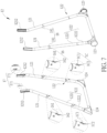
- FIG. 7 is a diagram of the leg assembly 12 according to the embodiment of the present invention.
- each lower support 122 includes a first segment 1221 and a second segment 1222.
- the second segment 1222 is detachably installed on the first segment 1221.
- the two front second segments 1222 are connected to each other to form a U-shaped structure, and the two rear second segments 1222 are connected to each other to form another U-shaped structure.
- the leg assembly 12 can include two wheels 123 and two stands 124.
- FIG. 12 is a schematic diagram of a child carrier 1' in a high chair mode according to another embodiment of the present invention.
- the child carrier 1' includes two lower supports 122'.
- Each lower support 122' can be an integral structure, and there is no stand or wheel disposed on the lower support 122'.
- the child carrier 1 further includes a releasing module.
- the releasing module includes a support releasing assembly 16 for allowing or restraining movement of the corresponding lower support 122 relative the corresponding upper support 121 and a segment releasing assembly 1C for allowing or restraining movement of the corresponding second segment 1222 relative to the corresponding first segment 1221.
- the support releasing assembly 16 includes four support engaging components 161, four support engaging slot structures 162, and four support resilient components, which are not shown in the figures.
- the four support engaging components 161 are respectively movably disposed on the four upper supports 121.
- the four support engaging slot structures 162 are respectively formed on the four lower supports 122.
- the four support resilient components biases the four support engaging components 161 to engage with the four support engaging slot structures 162 respectively.
- the segment releasing assembly 1C includes four segment engaging components 1C1, four segment engaging slot structures 1C2, and four segment resilient components, which are not shown in the figures.
- the four segment engaging components 1C1 are respectively movably disposed on the four first segments 1221.
- the four segment engaging slot structures 1C2 are respectively formed on the four second segments 1222.
- the four segment resilient components biases the four segment engaging components 1C1 to engage with the four segment engaging slot structures 1C2 respectively.
- At least one first guiding portion 1211 is formed on a lower end of each upper support 121.
- At least one second guiding portion which is not shown in the figures, is formed on an upper end of each lower support 122.
- the first guiding portion 1211 can cooperate with the second guiding portion to guide the movement of the lower support 122 relative to the upper support 121 to ensure the lower support 122 to be installed on the upper support 121 properly.
- the lower support 122 includes a similar mechanism to guide the movement of the second segment 1222 relative to the first segment 1221. Detailed description is omitted herein for simplicity.
- the four support engaging components 161 can be pressed to move inwardly to resiliently deform the four support resilient components, so that the four upper supports 121 can be inserted into the four lower supports 122 without any interference.
- the four resiliently deformed support resilient components can drive the four support engaging components 161 to engage with the four support engaging slot structures 162 respectively, so that the four lower supports 122 can respectively engage with the four upper supports 121 by engagement of the four support engaging components 161 and the four support engaging slot structures 162.
- the four support engaging components 161 can be pressed to move inwardly to respectively disengage from the four support engaging slot structures 162, so that the four upper supports 121 can be withdrawn from the four lower supports 122 without any interference.
- each support engaging component 161 can be pressed by the corresponding lower support 122 during insertion of the corresponding upper support 121 into the corresponding lower support 122.
- the caregiver does not have to press the support engaging component 161 manually during the insertion of the upper support 121 into the lower support 122, which facilitates the insertion of the upper support 121 into the lower support 122.
- the support resilient component can preferably be an elastic spring or torsional spring.
- the present invention is not limited thereto.
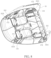
- FIG. 8 is a partial internal structural diagram of the booster seat 11 according to the embodiment of the present invention.
- the releasing module further includes a leg releasing assembly 17 for allowing or restraining movement of the leg assembly 12 relative the booster seat 11.
- the leg releasing assembly 17 includes four leg engaging components 171, four leg engaging slot structures 172, and four leg resilient components, which are not shown in the figures.
- the four leg engaging components 171 are respectively movably disposed on the four upper supports 121.
- the four leg engaging slot structures 172 are respectively formed on four sockets 111 located on four corners of the booster seat 11.
- the four leg resilient components bias the four leg engaging components 171 to engage with the four leg engaging slot structures 172 respectively.
- At least one third guiding portion 1212 is formed on an upper end of each upper support 121.
- At least one fourth guiding portion 1111 is formed inside each socket 111.
- the third guiding portion 1212 can cooperate with the fourth guiding portion 1111 to guide the movement of the upper support 121 relative to the booster seat 11 to ensure the upper support 121 to be installed into the socket 111 properly.
- the four leg engaging components 171 can be pressed to move inwardly to resiliently deform the four leg resilient components, so that the four upper supports 121 can be inserted into the four sockets 111 without any interference.
- the four resiliently deformed leg resilient components can drive the four leg engaging components 171 to engage with the four leg engaging slot structures 172 respectively, so that the four upper supports 121 can engage with the booster seat 11 by engagement of the four leg engaging components 171 and the four leg engaging slot structures 172.
- the four leg engaging components 171 can be pressed to move inwardly to respectively disengage from the four leg engaging slot structures 172, so that the four upper supports 121 can be withdrawn from the four sockets 111 without any interference.
- each leg engaging component 171 can be pressed by the corresponding socket 111 during insertion of the corresponding upper support 121 into the booster seat 11.
- the caregiver does not have to press the leg engaging component 171 manually during the insertion of the upper support 121 into the booster seat 11, which facilitates the insertion of the upper support 121 into the booster seat 11.
- leg resilient component can preferably be an elastic spring or torsional spring.
- the present invention is not limited thereto.
- the child carrier 1 further includes a leg rest releasing assembly 18 for allowing or restraining movement of the leg rest 15 relative to the two front upper supports 121.
- the leg rest releasing assembly 18 includes two leg rest engaging components 181, two leg rest engaging slot structures, which are not shown in the figures, and two leg rest resilient components, which are not shown in the figures.
- the two leg rest engaging components 181 are respectively movably disposed on the two front upper supports 121.
- the two leg rest engaging slot structures are respectively formed on two lateral sides of the leg rest 15.
- the two leg rest resilient components bias the two leg rest engaging components 181 to engage with the two leg rest engaging slot structures respectively.
- the two leg rest engaging components 181 can be pressed to move inwardly to resiliently deform the two leg resilient components, so that the leg rest 15 can be sleeved on the two front upper supports 121 without any interference.
- the two resiliently deformed leg rest resilient components can drive the two leg rest engaging components 181 to engage with the two leg lest engaging slot structures respectively, so that the leg rest 15 can engage with the two front upper supports 121 by engagement of the two leg rest engaging components 181 and the two leg rest engaging slot structures.
- the two leg rest engaging components 181 can be pressed to move inwardly to respectively disengage from the two leg rest engaging slot structures, so that the leg rest 15 can be removed from the two front upper supports 121 without any interference.
- each leg rest engaging component 181 can be pressed by the leg rest 15 during installation of the leg rest 15 onto the two front upper supports 121.
- the caregiver does not have to press the leg rest engaging component 181 manually during the installation of the leg rest 15 onto the two front upper supports 121, which facilitates the installation of the leg rest 15 onto the two front upper supports 121.
- leg rest resilient component can preferably be an elastic spring or torsional spring.
- the present invention is not limited thereto.
- the child carrier 1 further includes a tray releasing assembly 19 for allowing or restraining movement of the tray 14 and the booster seat 11.
- the tray releasing assembly 19 includes two tray engaging components 191, a plurality of tray engaging slot structures 192, a tray resilient component, which is not shown in the figures, and a tray driving component 193.
- the two tray engaging components 191 are respectively movably disposed on two lateral sides of the tray 14.
- the plurality of tray engaging slot structures 192 are formed on two lateral sides of the booster seat 11.
- the tray driving component 193 is movably disposed on a front side of the tray 14 for driving the two tray engaging components 191 to respectively engage with or disengage from the two tray engaging slot structures 192.
- the tray resilient component biases the tray driving component 193 to drive the two tray engaging components 191 to respectively engage with the two tray engaging slot structures 192.
- the tray driving component 193 can be operated to drive the two tray engaging components 191 to move to allow installation of the tray 14 without any interference.
- the tray driving component 193 can be released, so that the resiliently deformed tray resilient component can drive the tray driving component 193 to recover to drive the two tray engaging components 191 to respectively engage with the two tray engaging slot structures 192, so that the tray 14 can engage with the booster seat 11 by engagement of the two tray engaging components 191 and the two corresponding tray engaging slot structures 192.
- the tray driving component 193 can be operated to drive the two tray engaging components 191 to disengage from the two corresponding tray engaging slot structures 192 for allowing the movement of the tray 14 relative to the booster seat 11.
- the tray driving component 193 can be released to engage the two tray engaging components 191 with the two corresponding tray engaging slot structures 192 to position the tray 14.
- the tray driving component 193 can be operated to drive the two tray engaging components 191 to disengage from the two tray engaging slot structures 192, so that the tray 14 can be removed from the booster seat 11 without any interference.
- the tray resilient component can preferably be an elastic spring or torsional spring.
- the present invention is not limited thereto.
- FIG. 9 is a diagram of the seatback 13 according to the embodiment of the present invention.
- FIG. 10 is a partial diagram of the child carrier 1 as the seatback 13 has not been installed on the booster seat 11 yet according to the embodiment of the present invention.
- FIG. 11 is a partial diagram of the child carrier 1 as the seatback 13 is located at a used position according to the embodiment of the present invention.
- the seatback 13 includes two pivoting protrusions 131 and two retaining ribs 132 at two lateral sides.
- a first slot 112 and a second slot 113 communicated with the first slot 112 are formed on each lateral side of the booster seat 11.
- Each first slot 112 is open toward an outer periphery of the booster seat 11, and each second slot 113 is not open toward the outer periphery of the booster seat 11.
- the two pivoting protrusions 131 and the two retaining ribs 132 are accommodated in the two first slots 112 for allowing separation of the seatback 13 and the booster seat 11 when the seatback 13 is located at an unused position relative to the booster seat 11.
- the two pivoting protrusions 131 are respectively accommodated in the two first slots 112, and the two retaining ribs 132 are respectively at least partially accommodated the two second slots 113, i.e., the pivoting protrusion 131 and at least a portion of the retaining rib 132 are located in different slots, for restraining the separation of the seatback 13 and the booster seat 11 when the seatback 13 is located at the used position relative to the booster seat 11.
- the child carrier 1 further includes a seatback restraining assembly 1A for allowing or restraining the separation of the seatback 13 and the booster seat 11.
- the seatback restraining assembly 1A includes two restraining components 1A1 and two restraining portions 1A2.
- the two restraining components 1A1 are movably disposed on the booster seat 11.
- the two restraining portions 1A2 are respectively formed on the two pivoting protrusions 131.
- the two restraining components 1A1 can be operated to engage with or disengage from the two restraining portions 1A2 for restraining or allowing the separation of the seatback 13 and the booster seat 11.
- each pivoting protrusion 131 can be a cylinder-shaped structure, and each retaining rib 132 can be an arc-shaped structure.
- each first slot 112 can be an L-shaped structure, and each second slot 113 can be another arc-shaped structure corresponding to a shape of the corresponding retaining rib 132.
- the present invention is not limited to this embodiment.
- the numbers and the shapes of the pivoting protrusion 131, the retaining rib 132, the first slot 112 and the second slot 113 are not limited to this embodiment.
- each restraining component 1A1 can be a protrusion, and each restraining portion 1A2 can be a recess.
- the present invention is not limited to this embodiment.
- the two pivoting protrusions 131 and the two retaining ribs 132 can be placed in the two first slots 112, so as to locate the seatback 13 at the unused position and engage the two restraining components 1A1 with the two restraining portions 1A2. Afterwards, the seatback 13 can be rotated from the unused position to the used position to move the two retaining ribs 132 at least partially into the two second slots 113 for preventing unintentional separation of the seatback 13 and the booster seat 11.
- the seatback 13 When it is desired to detach the seatback 13 from the booster seat 11, the seatback 13 has to be rotated to the unused position to move the two pivoting protrusions 131 and the two retaining ribs 132 in the two first slots 112. Afterwards, the two restraining components 1A1 can be operated to disengage from two restraining slot structures 1A2, so that the seatback 13 can be removed from the booster seat 11 without any interference.
- an inclined surface can be formed on each restraining component 1A1 for facilitating the aforementioned engaging operation of the restraining component 1A1 and the restraining portion 1A2.
- the child carrier 1 further includes a seatback releasing assembly 1B for allowing or restraining rotary movement of the seatback 13 relative to the booster seat 11.
- the seatback releasing assembly 1B includes two seatback engaging components 1B1, a plurality of seatback engaging slot structures 1B2, a seatback resilient component, which is not shown in the figures, and a seatback driving component 1 B3.
- the two seatback engaging components 1B1 are respectively movably disposed on two lateral sides of the seatback 13, and the plurality of seatback engaging slot structures 1B2 are formed on the two lateral sides of the booster seat 11.
- the seatback driving component 1 B3 is movably disposed on a rear side of the seatback 13 for driving the two seatback engaging components 1B1 to respectively engage with or disengage from the two corresponding seatback engaging slot structures 1B2.
- the seatback resilient component biases the seatback driving component 1B3 to drive the two seatback engaging components 1B1 to respectively engage with the two corresponding seatback engaging slot structures 1B2.
- the seatback driving component 1B3 can be operated to drive the two seatback engaging components 1B1 to respectively disengage from the two corresponding seatback engaging slot structures 1B2 for allowing the rotary movement of the seatback 13 relative to the booster seat 11.
- the seatback driving component 1B3 can be released to engage the two seatback engaging components 1B1 with the two corresponding seatback engaging slot structures 1B2 to position the seatback 13.
- the seatback resilient component can preferably be an elastic spring or torsional spring.
- the present invention is not limited thereto.
- the present invention allows a caregiver to switch the child carrier among the high chair mode, the youth chair mode and the booster mode by detaching the lower support only or detaching the upper supports together with the lower supports, so as to position the booster seat at different desired heights.
- the present invention further allows the caregiver to install or remove at least one of the seatback, the tray and the leg rest to provide different features to satisfy the child's needs no matter when the child carrier is in the high chair mode, the youth chair mode or the booster mode. Therefore, the present invention is not only user-friendly but also flexible in use.
Landscapes
- Seats For Vehicles (AREA)
Abstract
Description
- The present invention relates to child carriers according to the pre-characterizing clauses of
claim 1. - With development of the economy and advancement of the technology, there are more and more consumer goods for bringing convenience in people's life. A child carrier is one of the consumer goods. There are various types of child carriers available in the market, such as a child high chair or a child booster seat, and designed for accommodating children with different ages. A caregiver has to choose a right child carrier according to a child's age. Currently, there are some conventional child carriers switchable between different modes to accommodate children with different ages. However, such child carriers have complex structure and are not user-friendly enough. Therefore, there is a need to provide an improved child carrier which can be switched between with multiple using modes easily for accommodating children with different ages and/or in different activities.
- This is mind, the present invention aims at providing a child carrier which has simple structure and can be switched between with multiple using modes easily.
- This is achieved by child carriers according to
claim 1. The dependent claims pertain to corresponding further developments and improvements. - As will be seen more clearly from the detail description following below, the claimed child carrier includes a booster seat and a leg assembly. The leg assembly is detachably installed on the booster seat. The leg assembly includes at least one upper support and at least one lower support. The at least one upper support is detachably installed on the booster seat. The at least one lower support is detachably installed on the at least one upper support. The child carrier is in a high chair mode when the at least one lower support and the at least one upper support are respectively installed on the at least one upper support and the booster seat to connect the leg assembly to the booster seat, the child carrier is in a youth chair mode when the at least one upper support is installed on the booster seat and the at least one lower support is detached from the at least one upper support, and the child carrier is in a booster mode when the at least one upper support is detached from the booster seat to separate the leg assembly from the booster seat.
- According to an embodiment of the present invention, the at least one lower support includes at least one first segment and at least one second segment detachably installed on the at least one first segment.
- According to an embodiment of the present invention, the leg assembly further includes at least one wheel rotatably disposed the at least one second segment.
- According to an embodiment of the present invention, the at least one second segment includes two second segments, and the two second segments are connected to each other to cooperatively form a U-shaped structure.
- According to an embodiment of the present invention, the child carrier further includes a releasing module for allowing or restraining at least one of movement of the at least one second segment relative to the at least one first segment, movement of the at least one lower support relative to the at least one upper support and movement of the at least one upper support relative to the booster seat.
- According to an embodiment of the present invention, the child carrier further includes a leg rest detachably installed on the at least one upper support and a leg rest releasing assembly for allowing or restraining movement of the leg rest relative to the at least one upper support.
- According to an embodiment of the present invention, the child carrier further includes a tray detachably installed on the booster seat and a tray releasing assembly for allowing or restraining movement of the tray relative to the booster seat.
- According to an embodiment of the present invention, the child carrier further includes at least one guiding portion, and the at least one guiding portion is for guiding movement of the at least one lower support relative to the at least one upper support or movement of the at least one upper support relative to the booster seat.
- According to an embodiment of the present invention, the child carrier further includes a seatback detachably installed on the booster seat.
- According to an embodiment of the present invention, the seatback is rotatable relative to the booster seat.
- According to an embodiment of the present invention, the seatback includes at least one pivoting protrusion and at least one retaining rib. At least one first slot and at least one second slot communicated with the at least one first slot are formed on the booster seat. The at least one pivoting protrusion and the at least one retaining rib are accommodated in the at least one first slot when the seatback is located at an unused position relative to the booster seat, and the at least one pivoting protrusion and at least a portion of the at least one retaining rib are respectively accommodated in the at least one first slot and the at least one second slot when the seatback is located at a used position relative to the booster seat.
- According to an embodiment of the present invention, the at least one pivoting protrusion is a cylinder-shaped structure.
- According to an embodiment of the present invention, the at least one retaining rib is an arc-shaped structure.
- According to an embodiment of the present invention, the child carrier further includes a seatback releasing assembly for allowing or restraining a rotary movement of the seatback relative to the booster seat.
- According to an embodiment of the present invention, the child carrier further includes a seatback restraining assembly for allowing or restraining separation of the seatback and the booster seat.
- According to an embodiment of the present invention, the booster seat is a one-piece molded structure.
- Furthermore, according to another embodiment of the present invention, the claimed child carrier includes a booster seat and a leg assembly. The booster seat is a one-piece molded structure. The leg assembly is detachably installed on the booster seat. The leg assembly includes at least one upper support and at least one lower support. The at least one upper support is detachably installed on the booster seat. The at least one lower support is detachably installed on the at least one upper support. The child carrier is in a high chair mode when the at least one lower support and the at least one upper support are respectively installed on the at least one upper support and the booster seat to connect the leg assembly to the booster seat, the child carrier is in a youth chair mode when the at least one upper support is installed on the booster seat and the at least one lower support is detached from the at least one upper support, and the child carrier is in a booster mode when the at least one upper support is detached from the booster seat to separate the leg assembly from the booster seat.
- In summary, the present invention allows a caregiver to switch the child carrier among the high chair mode, the youth chair mode and the booster mode by detaching the lower support only or detaching the upper supports together with the lower supports, so as to position the booster seat at different desired heights. Besides, the present invention further allows the caregiver to install or remove at least one of the seatback, the tray and the leg rest to provide different features to satisfy the child's needs no matter when the child carrier is in the high chair mode, the youth chair mode or the booster mode. Therefore, the present invention is not only user-friendly but also flexible in use.
- These and other objectives of the present invention will no doubt become obvious to those of ordinary skill in the art after reading the following detailed description of the preferred embodiment that is illustrated in the various figures and drawings.
- In the following, the invention is further illustrated by way of example, taking reference to the accompanying drawings. Thereof
-
FIG. 1 is a schematic diagram of a child carrier in a high chair mode according to an embodiment of the present invention, -
FIG. 2 to FIG. 4 are schematic diagrams of the child carrier in a youth chair mode with different features according to the embodiment of the present invention, -
FIG. 5 is a schematic diagram of the child carrier in a booster mode according to the embodiment of the present invention, -
FIG. 6 is an exploded diagram of the child carrier according to the embodiment of the present invention, -
FIG. 7 is a diagram of a leg assembly according to the embodiment of the present invention, -
FIG. 8 is a partial internal structural diagram of a booster seat according to the embodiment of the present invention, -
FIG. 9 is a diagram of a seatback according to the embodiment of the present invention, -
FIG. 10 is a partial diagram of the child carrier as the seatback has not been installed on the booster seat yet according to the embodiment of the present invention, -
FIG. 11 is a partial diagram of the child carrier as the seatback is located at a used position according to the embodiment of the present invention, and -
FIG. 12 is a schematic diagram of a child carrier in a high chair mode according to another embodiment of the present invention. - In the following detailed description of the preferred embodiments, reference is made to the accompanying drawings which form a part hereof, and in which is shown by way of illustration specific embodiments in which the invention may be practiced. In this regard, directional terminology, such as "top," "bottom," "front," "back," etc., is used with reference to the orientation of the Figure(s) being described. The components of the present invention can be positioned in a number of different orientations. As such, the directional terminology is used for purposes of illustration and is in no way limiting. Accordingly, the drawings and descriptions will be regarded as illustrative in nature and not as restrictive.
- Please refer to
FIG. 1 to FIG. 6 .FIG. 1 is a schematic diagram of achild carrier 1 in a high chair mode according to an embodiment of the present invention.FIG. 2 to FIG. 4 are schematic diagrams of thechild carrier 1 in a youth chair mode with different features according to the embodiment of the present invention.FIG. 5 is a schematic diagram of thechild carrier 1 in a booster mode according to the embodiment of the present invention.FIG. 6 is an exploded diagram of thechild carrier 1 according to the embodiment of the present invention. As shown inFIG. 1 to FIG. 6 , thechild carrier 1 includes abooster seat 11, aleg assembly 12, aseatback 13, atray 14 and aleg rest 15. Thebooster seat 11 is for accommodating a child. Theleg assembly 12 is detachably installed on thebooster seat 11 for supporting thebooster seat 11. Theleg assembly 12 includes fourupper supports 121 and fourlower supports 122. Eachupper support 121 is detachably installed on thebooster seat 11. Eachlower support 122 is detachably installed on the corresponding upper support 121.Theseatback 13 is detachably installed on thebooster seat 11 and rotatable relative to thebooster seat 11 for supporting the child's back. Thetray 14 is detachably installed on thebooster seat 11 for supporting the child's goods, such as food and beverages. Theleg rest 15 is detachably installed on theleg assembly 12 for supporting the child's legs. - Preferably, in this embodiment, the
booster seat 11 can be a one-piece molded structure for implementing a goal of simplicity for both a manufacturer and a caregiver while still providing adequate strength and accommodating ergonomic requirements. The fourupper supports 121 and the fourlower supports 122 are separated structures. However, the present invention is not limited thereto. For example, in another embodiment, there can be only one upper support and one lower support detachably installed on the upper support. It depends on practical demands. - The present invention allows the caregiver to switch the
child carrier 1 among the high chair mode, the youth chair mode and the booster mode by detaching the fourlower supports 122 only or detaching the fourupper supports 121 together with the fourlower supports 122, so as to position thebooster seat 11 at different desired heights. Besides, the present invention further allows the caregiver to attach or remove at least one of theseatback 13, thetray 14 and theleg rest 15 to provide different features to satisfy the child's needs no matter when thechild carrier 1 is in the high chair mode, the youth chair mode or the booster mode. Therefore, the present invention is not only user-friendly but also flexible in use. - For example, when it is desired to switch the
child carrier 1 to the high chair mode as shown inFIG. 1 , the fourlower supports 122 and the fourupper supports 121 can be respectively installed on the fourupper supports 121 and thebooster seat 11 to connect theleg assembly 12 to thebooster seat 11, i.e., eachlower support 122 and the correspondingupper support 121 are joined together, and eachupper support 121 and thebooster seat 11 are joined together. Furthermore, theseatback 13 and thetray 14 can be installed on thebooster seat 11, and theleg rest 15 can be installed on the two front upper supports 121. In this using mode, the caregiver can feed the child at a higher position. - When it is desired to switch the
child carrier 1 to the youth chair mode as shown inFIG. 2 , the fourupper supports 121 can be installed on thebooster seat 11, and the fourlower supports 122 can respectively detached from the fourupper supports 121. Furthermore, theseatback 13 and thetray 14 can be detached from thebooster seat 11, and theleg rest 15 can be detached from the two front upper supports 121. In this using mode, the child can sit at a lower position without theleg rest 15. - When it is desired to switch the
child carrier 1 to the youth chair mode as shown inFIG. 3 , the fourupper supports 121 can be installed on thebooster seat 11, and the fourlower supports 122 can respectively detached from the fourupper supports 121. Furthermore, theseatback 13 and thetray 14 can be installed on thebooster seat 11, and theleg rest 15 can be installed on the two front upper supports 121. In this using mode, the caregiver can feed the child at a lower position. - When it is desired to switch the
child carrier 1 to the youth chair mode as shown inFIG. 4 , the fourupper supports 121 can be installed on thebooster seat 11, and the fourlower supports 122 can respectively detached from the fourupper supports 121. Furthermore, theseatback 13 and thetray 14 can be detached from thebooster seat 11, and theleg rest 15 can be installed on the two front upper supports 121. In this using mode, the child can sit at a lower position with theleg rest 15. - Besides, when it is desired to switch the
child carrier 1 to the booster mode as shown inFIG. 5 , the fourupper supports 121 can be detached from thebooster seat 11 to separate theleg assembly 12 from thebooster seat 11. Furthermore, theseatback 13 and thetray 14 can be detached from thebooster seat 11. In this using mode, the child carrier can be installed on an adult chair, and the child can sit on thebooster seat 11 without theleg assembly 12. - Please refer to
FIG. 7. FIG. 7 is a diagram of theleg assembly 12 according to the embodiment of the present invention. As shown inFIG. 6 andFIG. 7 , eachlower support 122 includes afirst segment 1221 and asecond segment 1222. Thesecond segment 1222 is detachably installed on thefirst segment 1221. Preferably, in this embodiment, the two frontsecond segments 1222 are connected to each other to form a U-shaped structure, and the two rearsecond segments 1222 are connected to each other to form another U-shaped structure. Furthermore, in this embodiment, theleg assembly 12 can include twowheels 123 and two stands 124. The twowheels 123 are respectively rotatably disposed on the two frontsecond segments 1222, and the two stands 124 are detachably installed on the two rearsecond segments 1222, so that it allows the caregiver to pull or drag thechild carrier 1 in the high chair mode more easily. However, the present invention is not limited to this embodiment. For example, please refer toFIG. 12. FIG. 12 is a schematic diagram of a child carrier 1' in a high chair mode according to another embodiment of the present invention. As shown inFIG. 12 , in this embodiment, the child carrier 1' includes two lower supports 122'. Each lower support 122' can be an integral structure, and there is no stand or wheel disposed on the lower support 122'. - Furthermore, the
child carrier 1 further includes a releasing module. The releasing module includes asupport releasing assembly 16 for allowing or restraining movement of the correspondinglower support 122 relative the correspondingupper support 121 and a segment releasing assembly 1C for allowing or restraining movement of the correspondingsecond segment 1222 relative to the correspondingfirst segment 1221. Specifically, thesupport releasing assembly 16 includes foursupport engaging components 161, four support engagingslot structures 162, and four support resilient components, which are not shown in the figures. The foursupport engaging components 161 are respectively movably disposed on the fourupper supports 121. The four support engagingslot structures 162 are respectively formed on the fourlower supports 122. The four support resilient components biases the foursupport engaging components 161 to engage with the four support engagingslot structures 162 respectively. - Similarly, the segment releasing assembly 1C includes four segment engaging components 1C1, four segment engaging slot structures 1C2, and four segment resilient components, which are not shown in the figures. The four segment engaging components 1C1 are respectively movably disposed on the four
first segments 1221. The four segment engaging slot structures 1C2 are respectively formed on the foursecond segments 1222. The four segment resilient components biases the four segment engaging components 1C1 to engage with the four segment engaging slot structures 1C2 respectively. - As shown in
FIG. 2 to FIG. 4 andFIG. 6 andFIG. 7 , at least onefirst guiding portion 1211 is formed on a lower end of eachupper support 121. At least one second guiding portion, which is not shown in the figures, is formed on an upper end of eachlower support 122. Thefirst guiding portion 1211 can cooperate with the second guiding portion to guide the movement of thelower support 122 relative to theupper support 121 to ensure thelower support 122 to be installed on theupper support 121 properly. Understandably, thelower support 122 includes a similar mechanism to guide the movement of thesecond segment 1222 relative to thefirst segment 1221. Detailed description is omitted herein for simplicity. - When it is desired to install the four
lower supports 122 on the fourupper supports 121, the foursupport engaging components 161 can be pressed to move inwardly to resiliently deform the four support resilient components, so that the fourupper supports 121 can be inserted into the fourlower supports 122 without any interference. When the foursupport engaging components 161 are respectively aligned with the four support engagingslot structures 162, the four resiliently deformed support resilient components can drive the foursupport engaging components 161 to engage with the four support engagingslot structures 162 respectively, so that the fourlower supports 122 can respectively engage with the fourupper supports 121 by engagement of the foursupport engaging components 161 and the four support engagingslot structures 162. - When it is desired to detach the four
lower supports 122 from the fourupper supports 121, the foursupport engaging components 161 can be pressed to move inwardly to respectively disengage from the four support engagingslot structures 162, so that the fourupper supports 121 can be withdrawn from the fourlower supports 122 without any interference. - Preferably, in this embodiment, an inclined surface can be formed on each
support engaging component 161. By such configuration, eachsupport engaging component 161 can be pressed by the correspondinglower support 122 during insertion of the correspondingupper support 121 into the correspondinglower support 122. The caregiver does not have to press thesupport engaging component 161 manually during the insertion of theupper support 121 into thelower support 122, which facilitates the insertion of theupper support 121 into thelower support 122. - Furthermore, the support resilient component can preferably be an elastic spring or torsional spring. However, the present invention is not limited thereto.
- Please refer to
FIG. 6 to FIG. 8 .FIG. 8 is a partial internal structural diagram of thebooster seat 11 according to the embodiment of the present invention. As shown inFIG. 6 to FIG. 8 , the releasing module further includes aleg releasing assembly 17 for allowing or restraining movement of theleg assembly 12 relative thebooster seat 11. Specifically, theleg releasing assembly 17 includes fourleg engaging components 171, four leg engagingslot structures 172, and four leg resilient components, which are not shown in the figures. The fourleg engaging components 171 are respectively movably disposed on the fourupper supports 121. The four leg engagingslot structures 172 are respectively formed on foursockets 111 located on four corners of thebooster seat 11. The four leg resilient components bias the fourleg engaging components 171 to engage with the four leg engagingslot structures 172 respectively. - As shown in
FIG. 6 to FIG. 8 , at least onethird guiding portion 1212 is formed on an upper end of eachupper support 121. At least onefourth guiding portion 1111 is formed inside eachsocket 111. Thethird guiding portion 1212 can cooperate with thefourth guiding portion 1111 to guide the movement of theupper support 121 relative to thebooster seat 11 to ensure theupper support 121 to be installed into thesocket 111 properly. - When it is desired to install the four
upper supports 121 on thebooster seat 11, the fourleg engaging components 171 can be pressed to move inwardly to resiliently deform the four leg resilient components, so that the fourupper supports 121 can be inserted into the foursockets 111 without any interference. When the fourleg engaging components 171 are respectively aligned with the four leg engagingslot structures 172, the four resiliently deformed leg resilient components can drive the fourleg engaging components 171 to engage with the four leg engagingslot structures 172 respectively, so that the fourupper supports 121 can engage with thebooster seat 11 by engagement of the fourleg engaging components 171 and the four leg engagingslot structures 172. - When it is desired to detach the four
upper supports 121 from thebooster seat 11, the fourleg engaging components 171 can be pressed to move inwardly to respectively disengage from the four leg engagingslot structures 172, so that the fourupper supports 121 can be withdrawn from the foursockets 111 without any interference. - Preferably, in this embodiment, an inclined surface can be formed on each
leg engaging component 171. By such configuration, eachleg engaging component 171 can be pressed by the correspondingsocket 111 during insertion of the correspondingupper support 121 into thebooster seat 11. The caregiver does not have to press theleg engaging component 171 manually during the insertion of theupper support 121 into thebooster seat 11, which facilitates the insertion of theupper support 121 into thebooster seat 11. - Furthermore, the leg resilient component can preferably be an elastic spring or torsional spring. However, the present invention is not limited thereto.
- As shown in
FIG. 6 to FIG. 8 , thechild carrier 1 further includes a legrest releasing assembly 18 for allowing or restraining movement of theleg rest 15 relative to the two front upper supports 121. Specifically, the legrest releasing assembly 18 includes two legrest engaging components 181, two leg rest engaging slot structures, which are not shown in the figures, and two leg rest resilient components, which are not shown in the figures. The two legrest engaging components 181 are respectively movably disposed on the two front upper supports 121. The two leg rest engaging slot structures are respectively formed on two lateral sides of theleg rest 15. The two leg rest resilient components bias the two legrest engaging components 181 to engage with the two leg rest engaging slot structures respectively. - When it is desired to install the
leg rest 15 on the two frontupper supports 121, the two legrest engaging components 181 can be pressed to move inwardly to resiliently deform the two leg resilient components, so that theleg rest 15 can be sleeved on the two frontupper supports 121 without any interference. When the two legrest engaging components 181 are respectively aligned with the two leg rest engaging slot structures, the two resiliently deformed leg rest resilient components can drive the two legrest engaging components 181 to engage with the two leg lest engaging slot structures respectively, so that theleg rest 15 can engage with the two frontupper supports 121 by engagement of the two legrest engaging components 181 and the two leg rest engaging slot structures. - When it is desired to detach the
leg rest 15 from the two frontupper supports 121, the two legrest engaging components 181 can be pressed to move inwardly to respectively disengage from the two leg rest engaging slot structures, so that theleg rest 15 can be removed from the two frontupper supports 121 without any interference. - Preferably, in this embodiment, an inclined surface can be formed on each leg
rest engaging component 181. By such configuration, each legrest engaging component 181 can be pressed by theleg rest 15 during installation of theleg rest 15 onto the two front upper supports 121. The caregiver does not have to press the legrest engaging component 181 manually during the installation of theleg rest 15 onto the two frontupper supports 121, which facilitates the installation of theleg rest 15 onto the two front upper supports 121. - Furthermore, the leg rest resilient component can preferably be an elastic spring or torsional spring. However, the present invention is not limited thereto.
- Please refer to
FIG. 2 to FIG. 4 andFIG. 6 . As shown inFIG. 2 to FIG. 4 andFIG. 6 , thechild carrier 1 further includes atray releasing assembly 19 for allowing or restraining movement of thetray 14 and thebooster seat 11. Specifically, thetray releasing assembly 19 includes twotray engaging components 191, a plurality of tray engagingslot structures 192, a tray resilient component, which is not shown in the figures, and atray driving component 193. The twotray engaging components 191 are respectively movably disposed on two lateral sides of thetray 14. The plurality of tray engagingslot structures 192 are formed on two lateral sides of thebooster seat 11. Thetray driving component 193 is movably disposed on a front side of thetray 14 for driving the twotray engaging components 191 to respectively engage with or disengage from the two tray engagingslot structures 192. The tray resilient component biases thetray driving component 193 to drive the twotray engaging components 191 to respectively engage with the two tray engagingslot structures 192. - When it is desired to install the
tray 14 on thebooster seat 11, thetray driving component 193 can be operated to drive the twotray engaging components 191 to move to allow installation of thetray 14 without any interference. When thetray 14 is installed on thebooster seat 11 and moved to a desired position, thetray driving component 193 can be released, so that the resiliently deformed tray resilient component can drive thetray driving component 193 to recover to drive the twotray engaging components 191 to respectively engage with the two tray engagingslot structures 192, so that thetray 14 can engage with thebooster seat 11 by engagement of the twotray engaging components 191 and the two corresponding tray engagingslot structures 192. - When it is desired to adjust a position of the
tray 14 relative to thebooster seat 11, thetray driving component 193 can be operated to drive the twotray engaging components 191 to disengage from the two corresponding tray engagingslot structures 192 for allowing the movement of thetray 14 relative to thebooster seat 11. When adjustment of thetray 14 is completed, thetray driving component 193 can be released to engage the twotray engaging components 191 with the two corresponding tray engagingslot structures 192 to position thetray 14. - When it is desired to detach the
tray 14 from thebooster seat 11, thetray driving component 193 can be operated to drive the twotray engaging components 191 to disengage from the two tray engagingslot structures 192, so that thetray 14 can be removed from thebooster seat 11 without any interference. - Furthermore, the tray resilient component can preferably be an elastic spring or torsional spring. However, the present invention is not limited thereto.
- Please refer to
FIG. 2 to FIG. 4 andFIG. 9 to FIG. 11 .FIG. 9 is a diagram of theseatback 13 according to the embodiment of the present invention.FIG. 10 is a partial diagram of thechild carrier 1 as theseatback 13 has not been installed on thebooster seat 11 yet according to the embodiment of the present invention.FIG. 11 is a partial diagram of thechild carrier 1 as theseatback 13 is located at a used position according to the embodiment of the present invention. As shown inFIG. 2 to FIG. 4 andFIG. 9 to FIG. 11 , theseatback 13 includes two pivotingprotrusions 131 and two retainingribs 132 at two lateral sides. Afirst slot 112 and asecond slot 113 communicated with thefirst slot 112 are formed on each lateral side of thebooster seat 11. Eachfirst slot 112 is open toward an outer periphery of thebooster seat 11, and eachsecond slot 113 is not open toward the outer periphery of thebooster seat 11. The two pivotingprotrusions 131 and the two retainingribs 132 are accommodated in the twofirst slots 112 for allowing separation of theseatback 13 and thebooster seat 11 when theseatback 13 is located at an unused position relative to thebooster seat 11. The two pivotingprotrusions 131 are respectively accommodated in the twofirst slots 112, and the two retainingribs 132 are respectively at least partially accommodated the twosecond slots 113, i.e., the pivotingprotrusion 131 and at least a portion of the retainingrib 132 are located in different slots, for restraining the separation of theseatback 13 and thebooster seat 11 when theseatback 13 is located at the used position relative to thebooster seat 11. - Besides, the
child carrier 1 further includes aseatback restraining assembly 1A for allowing or restraining the separation of theseatback 13 and thebooster seat 11. Specifically, theseatback restraining assembly 1A includes two restraining components 1A1 and two restraining portions 1A2. The two restraining components 1A1 are movably disposed on thebooster seat 11. The two restraining portions 1A2 are respectively formed on the two pivotingprotrusions 131. The two restraining components 1A1 can be operated to engage with or disengage from the two restraining portions 1A2 for restraining or allowing the separation of theseatback 13 and thebooster seat 11. - Preferably, in this embodiment, each pivoting
protrusion 131 can be a cylinder-shaped structure, and each retainingrib 132 can be an arc-shaped structure. Furthermore, eachfirst slot 112 can be an L-shaped structure, and eachsecond slot 113 can be another arc-shaped structure corresponding to a shape of the corresponding retainingrib 132. However, the present invention is not limited to this embodiment. Furthermore, the numbers and the shapes of the pivotingprotrusion 131, the retainingrib 132, thefirst slot 112 and thesecond slot 113 are not limited to this embodiment. For example, in another embodiment, there can be only one pivoting protrusion and one retaining rib at one side of the seatback, and one first slot and one second slot at one side of the booster seat. - Besides, preferably, in this embodiment, each restraining component 1A1 can be a protrusion, and each restraining portion 1A2 can be a recess. However, the present invention is not limited to this embodiment.
- When it is desired to install the
seatback 13 on thebooster seat 11, the two pivotingprotrusions 131 and the two retainingribs 132 can be placed in the twofirst slots 112, so as to locate theseatback 13 at the unused position and engage the two restraining components 1A1 with the two restraining portions 1A2. Afterwards, theseatback 13 can be rotated from the unused position to the used position to move the two retainingribs 132 at least partially into the twosecond slots 113 for preventing unintentional separation of theseatback 13 and thebooster seat 11. - When it is desired to detach the
seatback 13 from thebooster seat 11, theseatback 13 has to be rotated to the unused position to move the two pivotingprotrusions 131 and the two retainingribs 132 in the twofirst slots 112. Afterwards, the two restraining components 1A1 can be operated to disengage from two restraining slot structures 1A2, so that theseatback 13 can be removed from thebooster seat 11 without any interference. - Preferably, in this embodiment, an inclined surface can be formed on each restraining component 1A1 for facilitating the aforementioned engaging operation of the restraining component 1A1 and the restraining portion 1A2.
- As shown in
FIG. 2 to FIG. 4 andFIG. 9 to FIG. 11 , thechild carrier 1 further includes aseatback releasing assembly 1B for allowing or restraining rotary movement of theseatback 13 relative to thebooster seat 11. Specifically, theseatback releasing assembly 1B includes two seatback engaging components 1B1, a plurality of seatback engaging slot structures 1B2, a seatback resilient component, which is not shown in the figures, and aseatback driving component 1 B3. The two seatback engaging components 1B1 are respectively movably disposed on two lateral sides of theseatback 13, and the plurality of seatback engaging slot structures 1B2 are formed on the two lateral sides of thebooster seat 11. Theseatback driving component 1 B3 is movably disposed on a rear side of theseatback 13 for driving the two seatback engaging components 1B1 to respectively engage with or disengage from the two corresponding seatback engaging slot structures 1B2. The seatback resilient component biases the seatback driving component 1B3 to drive the two seatback engaging components 1B1 to respectively engage with the two corresponding seatback engaging slot structures 1B2. - When it is desired to adjust a position of the
seatback 13 relative to thebooster seat 11, the seatback driving component 1B3 can be operated to drive the two seatback engaging components 1B1 to respectively disengage from the two corresponding seatback engaging slot structures 1B2 for allowing the rotary movement of theseatback 13 relative to thebooster seat 11. When adjustment of theseatback 13 is completed, the seatback driving component 1B3 can be released to engage the two seatback engaging components 1B1 with the two corresponding seatback engaging slot structures 1B2 to position theseatback 13. - Furthermore, the seatback resilient component can preferably be an elastic spring or torsional spring. However, the present invention is not limited thereto.
- In contrast to the prior art, the present invention allows a caregiver to switch the child carrier among the high chair mode, the youth chair mode and the booster mode by detaching the lower support only or detaching the upper supports together with the lower supports, so as to position the booster seat at different desired heights. Besides, the present invention further allows the caregiver to install or remove at least one of the seatback, the tray and the leg rest to provide different features to satisfy the child's needs no matter when the child carrier is in the high chair mode, the youth chair mode or the booster mode. Therefore, the present invention is not only user-friendly but also flexible in use.
- Those skilled in the art will readily observe that numerous modifications and alterations of the device and method may be made while retaining the teachings of the invention. Accordingly, the above disclosure should be construed as limited only by the metes and bounds of the appended claims.
- The present application can also be defined with the following aspects:
- 1. A
child carrier 1, characterized in that thechild carrier 1 comprises:- a
booster seat 11; and - a
leg assembly 12 detachably installed on thebooster seat 11, theleg assembly 12 comprising:- at least one
upper support 121 detachably installed on thebooster seat 11; and - at least one
lower support 122 detachably installed on the at least oneupper support 121;
- at least one
- wherein the
child carrier 1 is in a high chair mode when the at least onelower support 122 and the at least oneupper support 121 are respectively installed on the at least oneupper support 121 and thebooster seat 11 to connect theleg assembly 12 to thebooster seat 11, thechild carrier 1 is in a youth chair mode when the at least oneupper support 121 is installed on thebooster seat 11 and the at least onelower support 122 is detached from the at least oneupper support 121, and thechild carrier 1 is in a booster mode when the at least oneupper support 121 is detached from thebooster seat 11 to separate theleg assembly 12 from thebooster seat 11.
- a
- 2. The
child carrier 1 ofaspect 1, characterized in that the at least onelower support 122 comprises at least onefirst segment 1221 and at least onesecond segment 1222 detachably installed on the at least onefirst segment 1221. - 3. The
child carrier 1 of aspect 2, characterized in that theleg assembly 12 further comprises at least onewheel 123 rotatably disposed the at least onesecond segment 1222. - 4. The
child carrier 1 of any one of aspects 2 and 3, characterized in that the at least onesecond segment 1222 comprises twosecond segments 1222, and the twosecond segments 1222 are connected to each other to cooperatively form a U-shaped structure. - 5. The
child carrier 1 of any one of aspects 2 to 4, characterized in that thechild carrier 1 further comprises a releasing module for allowing or restraining at least one of movement of the at least onesecond segment 1222 relative to the at least onefirst segment 1221, movement of the at least onelower support 122 relative to the at least oneupper support 121 and movement of the at least oneupper support 121 relative to thebooster seat 11. - 6. The
child carrier 1 of any one ofaspects 1 to 5, characterized in that thechild carrier 1 further comprises aleg rest 15 detachably installed on the at least oneupper support 121 and a legrest releasing assembly 18 for allowing or restraining movement of theleg rest 15 relative to the at least oneupper support 121. - 7. The
child carrier 1 of any one ofaspects 1 to 6, characterized in that thechild carrier 1 further comprises atray 14 detachably installed on thebooster seat 11 and atray releasing assembly 19 for allowing or restraining movement of thetray 14 relative to thebooster seat 11. - 8. The
child carrier 1 of any one ofaspects 1 to 7, characterized in that thechild carrier 1 further comprises aseatback 13 detachably installed on thebooster seat 11. - 9. The
child carrier 1 of aspect 8, characterized in that theseatback 13 is rotatable relative to thebooster seat 11. - 10. The
child carrier 1 of aspect 9, characterized in that theseatback 13 comprises at least one pivotingprotrusion 131 and at least one retainingrib 132, at least onefirst slot 112 and at least onesecond slot 113 communicated with the at least onefirst slot 112 are formed on thebooster seat 11, the at least one pivotingprotrusion 131 and the at least one retainingrib 132 are accommodated in the at least onefirst slot 112 when theseatback 13 is located at an unused position relative to thebooster seat 11, and the at least one pivotingprotrusion 131 and at least a portion of the at least one retainingrib 132 are respectively accommodated in the at least onefirst slot 112 and the at least onesecond slot 113 when theseatback 13 is located at a used position relative to thebooster seat 11. - 11. The
child carrier 1 of aspect 10, characterized in that the at least one pivotingprotrusion 131 is a cylinder-shaped structure. - 12. The
child carrier 1 of aspect 10, characterized in that the at least one retainingrib 132 is an arc-shaped structure. - 13. The
child carrier 1 of any one of aspects 9 to 12, characterized in that thechild carrier 1 further comprises aseatback releasing assembly 1B for allowing or restraining a rotary movement of theseatback 13 relative to thebooster seat 11. - 14. The
child carrier 1 of any one of aspects 8 to 13, characterized in that thechild carrier 1 further comprises aseatback restraining assembly 1A for allowing or restraining separation of theseatback 13 and thebooster seat 11. - 15. A
child carrier 1, characterized in that thechild carrier 1 comprises:- a
booster seat 11 being a one-piece molded structure; and - a
leg assembly 12 detachably installed on thebooster seat 11, theleg assembly 12 comprising:- at least one
upper support 121 detachably installed on thebooster seat 11; and - at least one
lower support 122 detachably installed on the at least oneupper support 121;
- at least one
child carrier 1 is in a high chair mode when the at least onelower support 122 and the at least oneupper support 121 are respectively installed on the at least oneupper support 121 and thebooster seat 11 to connect theleg assembly 12 to thebooster seat 11, thechild carrier 1 is in a youth chair mode when the at least oneupper support 121 is installed on thebooster seat 11 and the at least onelower support 122 is detached from the at least oneupper support 121, and thechild carrier 1 is in a booster mode when the at least oneupper support 121 is detached from thebooster seat 11 to separate theleg assembly 12 from thebooster seat 11. - a
Claims (15)
- A child carrier (1) comprising:a booster seat (11); anda leg assembly (12) detachably installed on the booster seat (11), the leg assembly (12) comprising:at least one upper support (121) detachably installed on the booster seat (11); andat least one lower support (122) detachably installed on the at least one upper support (121);wherein the child carrier (1) is in a high chair mode when the at least one lower support (122) and the at least one upper support (121) are respectively installed on the at least one upper support (121) and the booster seat (11) to connect the leg assembly (12) to the booster seat (11), the child carrier (1) is in a youth chair mode when the at least one upper support (121) is installed on the booster seat (11) and the at least one lower support (122) is detached from the at least one upper support (121), and the child carrier (1) is in a booster mode when the at least one upper support (121) is detached from the booster seat (11) to separate the leg assembly (12) from the booster seat (11),characterized in that at least one socket (111) is formed on the booster seat (11), and
wherein an upper end of the at least one upper support (121) is insertable into the at least one socket (111) when the at least one upper support (121) is installed on the booster seat (11). - The child carrier (1) of claim 1, characterized in that the at least one lower support (122) comprises at least one first segment (1221) and at least one second segment (1222) detachably installed on the at least one first segment (1221).
- The child carrier (1) of claim 2, characterized in that the leg assembly (12) further comprises at least one wheel (123) rotatably disposed the at least one second segment (1222).
- The child carrier (1) of any one of claims 2 and 3, characterized in that the at least one second segment (1222) comprises two second segments (1222), and the two second segments (1222) are connected to each other to cooperatively form a U-shaped structure.
- The child carrier (1) of any one of claims 2 to 4, characterized in that the child carrier (1) further comprises a releasing module for allowing or restraining at least one of movement of the at least one second segment (1222) relative to the at least one first segment (1221), movement of the at least one lower support (122) relative to the at least one upper support (121) and movement of the at least one upper support (121) relative to the booster seat (11).
- The child carrier (1) of any one of claims 1 to 5, characterized in that the child carrier (1) further comprises a leg rest (15) detachably installed on the at least one upper support (121) and a leg rest releasing assembly (18) for allowing or restraining movement of the leg rest (15) relative to the at least one upper support (121).
- The child carrier (1) of any one of claims 1 to 6, characterized in that the child carrier (1) further comprises a tray (14) detachably installed on the booster seat (11) and a tray releasing assembly (19) for allowing or restraining movement of the tray (14) relative to the booster seat (11).
- The child carrier (1) of any one of claims 1 to 7, wherein the child carrier (1) further comprises a seatback (13) detachably installed on the booster seat (11).
- The child carrier (1) of claim 8, wherein the seatback (13) is rotatable relative to the booster seat (11).
- The child carrier (1) of claim 9, wherein the seatback (13) comprises at least one pivoting protrusion (131) and at least one retaining rib (132), at least one first slot (112) and at least one second slot (113) communicated with the at least one first slot (112) are formed on the booster seat (11), the at least one pivoting protrusion (131) and the at least one retaining rib (132) are accommodated in the at least one first slot (112) when the seatback (13) is located at an unused position relative to the booster seat (11), and the at least one pivoting protrusion (131) and at least a portion of the at least one retaining rib (132) are respectively accommodated in the at least one first slot (112) and the at least one second slot (113) when the seatback (13) is located at a used position relative to the booster seat (11).
- The child carrier (1) of claim 10, characterized in that the at least one pivoting protrusion (131) is a cylinder-shaped structure.
- The child carrier (1) of claim 10, characterized in that the at least one retaining rib (132) is an arc-shaped structure.
- The child carrier (1) of any one of claims 9 to 12, characterized in that the child carrier (1) further comprises a seatback releasing assembly (1B) for allowing or restraining a rotary movement of the seatback (13) relative to the booster seat (11).
- The child carrier (1) of any one of claims 8 to 13, characterized in that the child carrier (1) further comprises a seatback restraining assembly (1A) for allowing or restraining separation of the seatback (13) and the booster seat (11).
- The child carrier (1) of any preceding claim, wherein the booster seat (11) is a one-piece molded structure.
Priority Applications (1)
| Application Number | Priority Date | Filing Date | Title |
|---|---|---|---|
| EP25171278.2A EP4563043A3 (en) | 2019-05-08 | 2020-05-08 | Child carrier |
Applications Claiming Priority (3)
| Application Number | Priority Date | Filing Date | Title |
|---|---|---|---|
| US201962844948P | 2019-05-08 | 2019-05-08 | |
| US201962884283P | 2019-08-08 | 2019-08-08 | |
| EP20173623.8A EP3735865B1 (en) | 2019-05-08 | 2020-05-08 | Child carrier |
Related Parent Applications (1)
| Application Number | Title | Priority Date | Filing Date |
|---|---|---|---|
| EP20173623.8A Division EP3735865B1 (en) | 2019-05-08 | 2020-05-08 | Child carrier |
Related Child Applications (2)
| Application Number | Title | Priority Date | Filing Date |
|---|---|---|---|
| EP25171278.2A Division EP4563043A3 (en) | 2019-05-08 | 2020-05-08 | Child carrier |
| EP25171278.2A Division-Into EP4563043A3 (en) | 2019-05-08 | 2020-05-08 | Child carrier |
Publications (3)
| Publication Number | Publication Date |
|---|---|
| EP4252592A2 true EP4252592A2 (en) | 2023-10-04 |
| EP4252592A3 EP4252592A3 (en) | 2024-03-27 |
| EP4252592B1 EP4252592B1 (en) | 2025-06-25 |
Family
ID=70680218
Family Applications (3)
| Application Number | Title | Priority Date | Filing Date |
|---|---|---|---|
| EP20173623.8A Active EP3735865B1 (en) | 2019-05-08 | 2020-05-08 | Child carrier |
| EP23193170.0A Active EP4252592B1 (en) | 2019-05-08 | 2020-05-08 | Child carrier |
| EP25171278.2A Pending EP4563043A3 (en) | 2019-05-08 | 2020-05-08 | Child carrier |
Family Applications Before (1)
| Application Number | Title | Priority Date | Filing Date |
|---|---|---|---|
| EP20173623.8A Active EP3735865B1 (en) | 2019-05-08 | 2020-05-08 | Child carrier |
Family Applications After (1)
| Application Number | Title | Priority Date | Filing Date |
|---|---|---|---|
| EP25171278.2A Pending EP4563043A3 (en) | 2019-05-08 | 2020-05-08 | Child carrier |
Country Status (3)
| Country | Link |
|---|---|
| US (3) | US11224298B2 (en) |
| EP (3) | EP3735865B1 (en) |
| CN (2) | CN117678873A (en) |
Families Citing this family (7)
| Publication number | Priority date | Publication date | Assignee | Title |
|---|---|---|---|---|
| USD969506S1 (en) | 2021-02-03 | 2022-11-15 | Wonderland Switzerland Ag | Child chair |
| CN115703385A (en) * | 2021-08-09 | 2023-02-17 | 明门瑞士股份有限公司 | Connection adjustment mechanism and child carrier |
| US12016469B2 (en) | 2021-08-22 | 2024-06-25 | Skip Hop, Inc. | Convertible child chair |
| US12383075B2 (en) * | 2021-08-25 | 2025-08-12 | Wonderland Switzerland Ag | Adjustable chair assembly |
| AU2023373555A1 (en) * | 2022-11-04 | 2025-05-22 | Wonderland Switzerland Ag | High chair |
| WO2025036937A1 (en) * | 2023-08-15 | 2025-02-20 | Wonderland Switzerland Ag | Child chair and backrest connecting structure thereof |
| US12551028B1 (en) * | 2024-11-29 | 2026-02-17 | Taizhou Xiaotanglang Infant and Child Products Co., Ltd. | Children's dining chair |
Family Cites Families (26)
| Publication number | Priority date | Publication date | Assignee | Title |
|---|---|---|---|---|
| US2546439A (en) * | 1946-07-26 | 1951-03-27 | Green Leon | Knockdown table or stool |
| US5951102A (en) * | 1996-12-27 | 1999-09-14 | Evenflo Company, Inc. | High chair |
| US6702384B1 (en) * | 2001-10-12 | 2004-03-09 | Christopher D. Brown | Support device |
| US20030102700A1 (en) * | 2001-12-04 | 2003-06-05 | Fang-Sheng Lin | Combination type bath chair |
| US20050238422A1 (en) * | 2004-04-27 | 2005-10-27 | Hsi-Lu Hung | Snap connecting device |
| US8794703B2 (en) * | 2006-03-27 | 2014-08-05 | Allan Bateman | Adjustable folding chair for extended periods of seating |
| US7673934B2 (en) * | 2007-06-26 | 2010-03-09 | Wonderland Nurserygoods Co., Ltd. | Dual purpose high chair |
| FR2919164B1 (en) * | 2007-07-25 | 2009-09-25 | Beaba Sa | HIGH CHAIR FOR CHILDREN. |
| CN101844530B (en) * | 2009-03-25 | 2013-03-13 | 明门香港股份有限公司 | Toddler booster chair |
| GB2476455A (en) * | 2009-12-17 | 2011-06-29 | Pao-Hsien Cheng | A high chair with detachable upper and lower sections utilising a sliding snap fit coupling mechanism |
| US8602490B2 (en) * | 2010-10-08 | 2013-12-10 | Baby Trend Inc. | Highchair with adapter for attaching a car seat |
| US8382390B2 (en) * | 2010-10-29 | 2013-02-26 | Pao-Hsien Cheng | Quick coupling structure of leg for table or chair |
| CN102727002B (en) * | 2011-03-31 | 2015-05-20 | 明门香港股份有限公司 | Folding baby chair with adjustable back slope |
| US9101225B2 (en) * | 2011-09-13 | 2015-08-11 | Kids Ii, Inc. | Convertible high chair |
| CN103723181B (en) * | 2012-10-15 | 2016-12-21 | 明门香港股份有限公司 | Canopy device, infant carrier and canopy connecting mechanism thereof |
| CN202843041U (en) * | 2012-10-26 | 2013-04-03 | 乐明 | Multifunctional dining chair for children |
| DE102013109283A1 (en) * | 2013-08-27 | 2015-03-05 | Yvonne Peters | High chair for washing a toddler |
| US9635955B2 (en) * | 2014-06-12 | 2017-05-02 | Artsana Usa, Inc. | Multi-mode high chair |
| CN105708226A (en) * | 2014-12-19 | 2016-06-29 | 明门香港股份有限公司 | High chair assembly with removable tray that can be transformed into different states of use |
| CN104799622B (en) * | 2015-04-13 | 2018-03-16 | 上海三问投资控股集团有限公司 | A kind of baby seat |
| US11723477B2 (en) * | 2015-04-25 | 2023-08-15 | Kids2, Inc. | Convertible highchair |
| CN206213662U (en) * | 2016-07-25 | 2017-06-06 | 谢明伦 | Children's seat |
| US10562419B2 (en) * | 2016-08-19 | 2020-02-18 | Graco Children's Products, Inc. | Child's booster seat |
| DE102018204778B4 (en) * | 2017-04-04 | 2019-06-27 | Wonderland Switzerland Ag | Multifunctional highchair |
| CN107898216B (en) | 2017-11-17 | 2023-07-21 | 浙江工业大学 | Multifunctional combined children's dining chair |
| CN108720426A (en) | 2018-06-29 | 2018-11-02 | 兔迪昵(厦门)贸易有限公司 | A kind of children's chairs |
-
2020
- 2020-05-07 US US16/868,563 patent/US11224298B2/en active Active
- 2020-05-08 EP EP20173623.8A patent/EP3735865B1/en active Active
- 2020-05-08 EP EP23193170.0A patent/EP4252592B1/en active Active
- 2020-05-08 CN CN202311631095.2A patent/CN117678873A/en active Pending
- 2020-05-08 CN CN202010383661.2A patent/CN111904209B/en active Active
- 2020-05-08 EP EP25171278.2A patent/EP4563043A3/en active Pending
-
2021
- 2021-12-14 US US17/551,141 patent/US11766137B2/en active Active
-
2023
- 2023-09-04 US US18/241,911 patent/US20230404287A1/en active Pending
Also Published As
| Publication number | Publication date |
|---|---|
| US11766137B2 (en) | 2023-09-26 |
| EP4563043A2 (en) | 2025-06-04 |
| US20220104634A1 (en) | 2022-04-07 |
| EP3735865A1 (en) | 2020-11-11 |
| EP4252592A3 (en) | 2024-03-27 |
| US20230404287A1 (en) | 2023-12-21 |
| CN111904209A (en) | 2020-11-10 |
| CN111904209B (en) | 2023-12-19 |
| EP4252592B1 (en) | 2025-06-25 |
| US11224298B2 (en) | 2022-01-18 |
| CN117678873A (en) | 2024-03-12 |
| EP4563043A3 (en) | 2025-07-02 |
| US20200352349A1 (en) | 2020-11-12 |
| EP3735865B1 (en) | 2023-09-13 |
Similar Documents
| Publication | Publication Date | Title |
|---|---|---|
| EP3735865A1 (en) | Child carrier | |
| US10413085B2 (en) | Adjusting mechanism and related child carrier | |
| US12121157B2 (en) | Child tray assembly | |
| US8011722B2 (en) | Foldable frame with detachable infant carrier | |
| US11597421B2 (en) | Child carrier | |
| US20240343284A1 (en) | Shopping cart | |
| TW202346134A (en) | Fixing device and passenger device as well as carrying device using the same | |
| CN218198465U (en) | Adapter Kit and Stroller Frame | |
| CN118078068A (en) | Height adjustment mechanism, seat adjustment device, rotation adjustment mechanism and chair | |
| EP4728938A2 (en) | Dinner tray, dinner tray holder and child carrier | |
| CN223929863U (en) | Basket that can be attached to a stroller | |
| CN110962710B (en) | Child seat | |
| US20260020690A1 (en) | Tray and child chair | |
| CN121220908A (en) | Child car seat |
Legal Events
| Date | Code | Title | Description |
|---|---|---|---|
| PUAI | Public reference made under article 153(3) epc to a published international application that has entered the european phase |
Free format text: ORIGINAL CODE: 0009012 |
|
| STAA | Information on the status of an ep patent application or granted ep patent |
Free format text: STATUS: THE APPLICATION HAS BEEN PUBLISHED |
|
| AC | Divisional application: reference to earlier application |
Ref document number: 3735865 Country of ref document: EP Kind code of ref document: P |
|
| AK | Designated contracting states |
Kind code of ref document: A2 Designated state(s): AL AT BE BG CH CY CZ DE DK EE ES FI FR GB GR HR HU IE IS IT LI LT LU LV MC MK MT NL NO PL PT RO RS SE SI SK SM TR |
|
| REG | Reference to a national code |
Ref country code: DE Ref legal event code: R079 Free format text: PREVIOUS MAIN CLASS: A47D0001100000 Ipc: A47D0001000000 Ref country code: DE Ref legal event code: R079 Ref document number: 602020053609 Country of ref document: DE Free format text: PREVIOUS MAIN CLASS: A47D0001100000 Ipc: A47D0001000000 |
|
| PUAL | Search report despatched |
Free format text: ORIGINAL CODE: 0009013 |
|
| AK | Designated contracting states |
Kind code of ref document: A3 Designated state(s): AL AT BE BG CH CY CZ DE DK EE ES FI FR GB GR HR HU IE IS IT LI LT LU LV MC MK MT NL NO PL PT RO RS SE SI SK SM TR |
|
| RIC1 | Information provided on ipc code assigned before grant |
Ipc: A47D 1/10 20060101ALI20240219BHEP Ipc: A47D 1/00 20060101AFI20240219BHEP |
|
| STAA | Information on the status of an ep patent application or granted ep patent |
Free format text: STATUS: REQUEST FOR EXAMINATION WAS MADE |
|
| 17P | Request for examination filed |
Effective date: 20240709 |
|
| RBV | Designated contracting states (corrected) |
Designated state(s): AL AT BE BG CH CY CZ DE DK EE ES FI FR GB GR HR HU IE IS IT LI LT LU LV MC MK MT NL NO PL PT RO RS SE SI SK SM TR |
|
| GRAP | Despatch of communication of intention to grant a patent |
Free format text: ORIGINAL CODE: EPIDOSNIGR1 |
|
| STAA | Information on the status of an ep patent application or granted ep patent |
Free format text: STATUS: GRANT OF PATENT IS INTENDED |
|
| INTG | Intention to grant announced |
Effective date: 20241210 |
|
| GRAS | Grant fee paid |
Free format text: ORIGINAL CODE: EPIDOSNIGR3 |
|
| GRAA | (expected) grant |
Free format text: ORIGINAL CODE: 0009210 |
|
| STAA | Information on the status of an ep patent application or granted ep patent |
Free format text: STATUS: THE PATENT HAS BEEN GRANTED |
|
| AC | Divisional application: reference to earlier application |
Ref document number: 3735865 Country of ref document: EP Kind code of ref document: P |
|
| AK | Designated contracting states |
Kind code of ref document: B1 Designated state(s): AL AT BE BG CH CY CZ DE DK EE ES FI FR GB GR HR HU IE IS IT LI LT LU LV MC MK MT NL NO PL PT RO RS SE SI SK SM TR |
|
| REG | Reference to a national code |
Ref country code: GB Ref legal event code: FG4D |
|
| REG | Reference to a national code |
Ref country code: CH Ref legal event code: EP |
|
| REG | Reference to a national code |
Ref country code: CH Ref legal event code: EP |
|
| REG | Reference to a national code |
Ref country code: IE Ref legal event code: FG4D |
|
| REG | Reference to a national code |
Ref country code: DE Ref legal event code: R096 Ref document number: 602020053609 Country of ref document: DE |
|
| P01 | Opt-out of the competence of the unified patent court (upc) registered |
Free format text: CASE NUMBER: UPC_APP_0649_4252592/2025 Effective date: 20250721 |
|
| P02 | Opt-out of the competence of the unified patent court (upc) changed |
Free format text: CASE NUMBER: UPC_APP_0996_4252592/2025 Effective date: 20250724 |
|
| PG25 | Lapsed in a contracting state [announced via postgrant information from national office to epo] |
Ref country code: FI Free format text: LAPSE BECAUSE OF FAILURE TO SUBMIT A TRANSLATION OF THE DESCRIPTION OR TO PAY THE FEE WITHIN THE PRESCRIBED TIME-LIMIT Effective date: 20250625 |
|
| REG | Reference to a national code |
Ref country code: LT Ref legal event code: MG9D |
|
| PG25 | Lapsed in a contracting state [announced via postgrant information from national office to epo] |
Ref country code: GR Free format text: LAPSE BECAUSE OF FAILURE TO SUBMIT A TRANSLATION OF THE DESCRIPTION OR TO PAY THE FEE WITHIN THE PRESCRIBED TIME-LIMIT Effective date: 20250926 Ref country code: NO Free format text: LAPSE BECAUSE OF FAILURE TO SUBMIT A TRANSLATION OF THE DESCRIPTION OR TO PAY THE FEE WITHIN THE PRESCRIBED TIME-LIMIT Effective date: 20250925 |
|
| PG25 | Lapsed in a contracting state [announced via postgrant information from national office to epo] |
Ref country code: BG Free format text: LAPSE BECAUSE OF FAILURE TO SUBMIT A TRANSLATION OF THE DESCRIPTION OR TO PAY THE FEE WITHIN THE PRESCRIBED TIME-LIMIT Effective date: 20250625 |
|
| PG25 | Lapsed in a contracting state [announced via postgrant information from national office to epo] |
Ref country code: HR Free format text: LAPSE BECAUSE OF FAILURE TO SUBMIT A TRANSLATION OF THE DESCRIPTION OR TO PAY THE FEE WITHIN THE PRESCRIBED TIME-LIMIT Effective date: 20250625 |
|
| PG25 | Lapsed in a contracting state [announced via postgrant information from national office to epo] |
Ref country code: RS Free format text: LAPSE BECAUSE OF FAILURE TO SUBMIT A TRANSLATION OF THE DESCRIPTION OR TO PAY THE FEE WITHIN THE PRESCRIBED TIME-LIMIT Effective date: 20250925 |
|
| PG25 | Lapsed in a contracting state [announced via postgrant information from national office to epo] |
Ref country code: LV Free format text: LAPSE BECAUSE OF FAILURE TO SUBMIT A TRANSLATION OF THE DESCRIPTION OR TO PAY THE FEE WITHIN THE PRESCRIBED TIME-LIMIT Effective date: 20250625 |
|
| REG | Reference to a national code |
Ref country code: NL Ref legal event code: MP Effective date: 20250625 |
|
| PG25 | Lapsed in a contracting state [announced via postgrant information from national office to epo] |
Ref country code: NL Free format text: LAPSE BECAUSE OF FAILURE TO SUBMIT A TRANSLATION OF THE DESCRIPTION OR TO PAY THE FEE WITHIN THE PRESCRIBED TIME-LIMIT Effective date: 20250625 |
|
| PG25 | Lapsed in a contracting state [announced via postgrant information from national office to epo] |
Ref country code: PT Free format text: LAPSE BECAUSE OF FAILURE TO SUBMIT A TRANSLATION OF THE DESCRIPTION OR TO PAY THE FEE WITHIN THE PRESCRIBED TIME-LIMIT Effective date: 20251027 |
|
| REG | Reference to a national code |
Ref country code: AT Ref legal event code: MK05 Ref document number: 1805545 Country of ref document: AT Kind code of ref document: T Effective date: 20250625 |
|
| PG25 | Lapsed in a contracting state [announced via postgrant information from national office to epo] |
Ref country code: IS Free format text: LAPSE BECAUSE OF FAILURE TO SUBMIT A TRANSLATION OF THE DESCRIPTION OR TO PAY THE FEE WITHIN THE PRESCRIBED TIME-LIMIT Effective date: 20251025 |
|
| PG25 | Lapsed in a contracting state [announced via postgrant information from national office to epo] |
Ref country code: AT Free format text: LAPSE BECAUSE OF FAILURE TO SUBMIT A TRANSLATION OF THE DESCRIPTION OR TO PAY THE FEE WITHIN THE PRESCRIBED TIME-LIMIT Effective date: 20250625 Ref country code: SM Free format text: LAPSE BECAUSE OF FAILURE TO SUBMIT A TRANSLATION OF THE DESCRIPTION OR TO PAY THE FEE WITHIN THE PRESCRIBED TIME-LIMIT Effective date: 20250625 |
|
| PG25 | Lapsed in a contracting state [announced via postgrant information from national office to epo] |
Ref country code: CZ Free format text: LAPSE BECAUSE OF FAILURE TO SUBMIT A TRANSLATION OF THE DESCRIPTION OR TO PAY THE FEE WITHIN THE PRESCRIBED TIME-LIMIT Effective date: 20250625 |
|
| PG25 | Lapsed in a contracting state [announced via postgrant information from national office to epo] |
Ref country code: PL Free format text: LAPSE BECAUSE OF FAILURE TO SUBMIT A TRANSLATION OF THE DESCRIPTION OR TO PAY THE FEE WITHIN THE PRESCRIBED TIME-LIMIT Effective date: 20250625 |
|
| PG25 | Lapsed in a contracting state [announced via postgrant information from national office to epo] |
Ref country code: EE Free format text: LAPSE BECAUSE OF FAILURE TO SUBMIT A TRANSLATION OF THE DESCRIPTION OR TO PAY THE FEE WITHIN THE PRESCRIBED TIME-LIMIT Effective date: 20250625 |
|
| PG25 | Lapsed in a contracting state [announced via postgrant information from national office to epo] |
Ref country code: SK Free format text: LAPSE BECAUSE OF FAILURE TO SUBMIT A TRANSLATION OF THE DESCRIPTION OR TO PAY THE FEE WITHIN THE PRESCRIBED TIME-LIMIT Effective date: 20250625 |
|
| PG25 | Lapsed in a contracting state [announced via postgrant information from national office to epo] |
Ref country code: ES Free format text: LAPSE BECAUSE OF FAILURE TO SUBMIT A TRANSLATION OF THE DESCRIPTION OR TO PAY THE FEE WITHIN THE PRESCRIBED TIME-LIMIT Effective date: 20250625 |
|
| PGFP | Annual fee paid to national office [announced via postgrant information from national office to epo] |
Ref country code: GB Payment date: 20260303 Year of fee payment: 7 |
|
| PG25 | Lapsed in a contracting state [announced via postgrant information from national office to epo] |
Ref country code: DK Free format text: LAPSE BECAUSE OF FAILURE TO SUBMIT A TRANSLATION OF THE DESCRIPTION OR TO PAY THE FEE WITHIN THE PRESCRIBED TIME-LIMIT Effective date: 20250625 |
|
| PG25 | Lapsed in a contracting state [announced via postgrant information from national office to epo] |
Ref country code: IT Free format text: LAPSE BECAUSE OF FAILURE TO SUBMIT A TRANSLATION OF THE DESCRIPTION OR TO PAY THE FEE WITHIN THE PRESCRIBED TIME-LIMIT Effective date: 20250625 |
|
| PGFP | Annual fee paid to national office [announced via postgrant information from national office to epo] |
Ref country code: FR Payment date: 20260224 Year of fee payment: 7 |
|
| PLBE | No opposition filed within time limit |
Free format text: ORIGINAL CODE: 0009261 |
|
| STAA | Information on the status of an ep patent application or granted ep patent |
Free format text: STATUS: NO OPPOSITION FILED WITHIN TIME LIMIT |
|
| REG | Reference to a national code |
Ref country code: CH Ref legal event code: L10 Free format text: ST27 STATUS EVENT CODE: U-0-0-L10-L00 (AS PROVIDED BY THE NATIONAL OFFICE) Effective date: 20260507 |