EP4252399B1 - Verfahren, vorrichtung und system zur erzeugung einer sr-richtlinie unter verwendung eines pfadberechnungselementprotokolls - Google Patents
Verfahren, vorrichtung und system zur erzeugung einer sr-richtlinie unter verwendung eines pfadberechnungselementprotokolls Download PDFInfo
- Publication number
- EP4252399B1 EP4252399B1 EP21905858.3A EP21905858A EP4252399B1 EP 4252399 B1 EP4252399 B1 EP 4252399B1 EP 21905858 A EP21905858 A EP 21905858A EP 4252399 B1 EP4252399 B1 EP 4252399B1
- Authority
- EP
- European Patent Office
- Prior art keywords
- policy
- pcep
- pce
- pcc
- message
- Prior art date
- Legal status (The legal status is an assumption and is not a legal conclusion. Google has not performed a legal analysis and makes no representation as to the accuracy of the status listed.)
- Active
Links
Images


Classifications
-
- H—ELECTRICITY
- H04—ELECTRIC COMMUNICATION TECHNIQUE
- H04L—TRANSMISSION OF DIGITAL INFORMATION, e.g. TELEGRAPHIC COMMUNICATION
- H04L45/00—Routing or path finding of packets in data switching networks
- H04L45/42—Centralised routing
-
- H—ELECTRICITY
- H04—ELECTRIC COMMUNICATION TECHNIQUE
- H04L—TRANSMISSION OF DIGITAL INFORMATION, e.g. TELEGRAPHIC COMMUNICATION
- H04L43/00—Arrangements for monitoring or testing data switching networks
- H04L43/06—Generation of reports
- H04L43/062—Generation of reports related to network traffic
-
- H—ELECTRICITY
- H04—ELECTRIC COMMUNICATION TECHNIQUE
- H04L—TRANSMISSION OF DIGITAL INFORMATION, e.g. TELEGRAPHIC COMMUNICATION
- H04L45/00—Routing or path finding of packets in data switching networks
- H04L45/24—Multipath
-
- H—ELECTRICITY
- H04—ELECTRIC COMMUNICATION TECHNIQUE
- H04L—TRANSMISSION OF DIGITAL INFORMATION, e.g. TELEGRAPHIC COMMUNICATION
- H04L45/00—Routing or path finding of packets in data switching networks
- H04L45/74—Address processing for routing
- H04L45/741—Routing in networks with a plurality of addressing schemes, e.g. with both IPv4 and IPv6
Definitions
- the present disclosure described herein in general, relates to network to a Software Defined Network (SDN) enabled network.
- SDN Software Defined Network
- the embodiments describes in the present disclosure relate to system, apparatuses and methods using a Path Computation Element Protocol (PCEP).
- PCEP Path Computation Element Protocol
- Segment Routing is a source-based routing technique that simplifies traffic engineering and management across network domains. It removes network state information from transit routers and nodes in the network and places the path state information into packet headers at an ingress node i.e. an ingress node may prepend a header to packets that contain a list of segments, which are instructions that are executed on subsequent nodes in the network. These instructions may be forwarding instructions, such as an instruction to forward a packet to a specific destination or interface. Segment routing works either on top of a MPLS network or on an IPv6 network. In an SR-MPLS network, segments are encoded as MPLS labels. Under SRv6, a new header called a Segment Routing Header (SRH) is used. Segments in a SRH are encoded in a list of IPv6 addresses.
- SR Segment Routing
- a Path Computation Element is an entity that is capable of computing a network path or route based on a network graph, and of applying computational constraints during the computation.
- the PCE entity is an application that can be located within a network node or component, on a server, etc.
- the PCE receives the path computation request from a Path Computation Client (PCC), the path computation request requesting a path initiating at the PCC.
- PCC Path Computation Client
- the PCE computes the path from the PCC to an egress node via an intermediate node in response to the path computation request, and assigns label information for a label switched path (LSP) from the PCC, the intermediate node, and the egress node.
- LSP label switched path
- the PCE sets up the LSP along the computed path by transmitting the label information directly to the PCC, the intermediate node, and the egress node for storage in a Forwarding Information Base (FIB).
- FIB Forwarding Information Base
- PCEP Path Computation Element Protocol
- PCC Path Computation Client
- PCE Path Computation Element
- MPLS Multiprotocol Label Switching
- PCE is used to compute the SR path in the SR networks.
- Path Computation Element Protocol (PCEP) has been extended to support this.
- PCEP Path Computation Element Protocol
- PCECC Central Controller
- a PCE-based central controller (PCECC) can simplify the processing of a distributed control plane by blending it with elements of SDN and without necessarily completely replacing it.
- PCECC allows the PCE to encode various Central Controller's Instructions (CCI) to be executed at the PCC.
- CCI Central Controller's Instructions
- An SR Policy is a framework that enables instantiation of an ordered list of segments on a node for implementing a source routing policy with a specific intent for traffic steering from that node.
- SR policy is built using any type of Segment Identifier (SID) including those associated with topological or service instructions.
- SID Segment Identifier
- An SR Policy is associated with one or more candidate paths (CP).
- a candidate path is the unit for signaling of an SR Policy to a headend via protocols like PCEP and the SR-Policy is carried as part of a new association type encoded along with these candidate path.
- An SR policy is identified by ⁇ headend, color, end-point> tuple.
- the headend is the node where the policy is instantiated/ implemented.
- the headend is specified as an IPv4 or IPv6 address and is expected to be unique in the domain.
- the endpoint indicates the destination of the policy.
- the endpoint is specified as an IPv4 or IPv6 address and is expected to be unique in the domain.
- the color is a 32-bit numerical value that associates the SR Policy with an intent (e.g. low-latency, high bandwidth, etc.).
- the endpoint and the color are used to automate the steering of service or transport routes on SR Policies.
- the SR policy defined in the above example defines two candidate paths (CP1 and CP2) and a preference of the candidate path is used to select the best candidate path for an SR Policy.
- Each candidate path (CP1 and CP2) is identified by a tuple ⁇ protocol-origin, originator, discriminator>.
- CP1 is the active candidate path (it is valid and it has the highest preference).
- the two Segment-Lists of CP1 are installed as the forwarding instantiation of SR policy POL1.
- SR policy is container information that remains constant and needs to be encoded along with each candidate path individually.
- BIDGOLI H ET AL "PCEP extensions for p2mp sr policy; draft-hsd-pce-sr-p2mp-policy-00.txt",PCEP EXTENSIONS FOR P2MP SR POLICY; DRAFT-HSD-PCE-SR-P2MP-POLICY-OO.TXT; INTERNET-DRAFT: NETWORK WORKING GROUP, INTERNET ENGINEERING TASK FORCE, IETF; STANDARDWORKINGDRAFT, INTERNET SOCIETY (ISOC) 4,https://tools.ietf.org/html/draft-hsd- pce-sr-p2mp-policy-00 and BIDGOLI H ET AL: "PCEP extensions for p2mp sr policy; draft-dhs- spring-pce-sr-p2mp-policy-00.txt",PCEP EXTENSIONS FOR P2MP SR POLICY; DRAFT-
- a main objective of the present disclosure is to provide a mechanism using PCEP to create SR policy independent of the candidate paths.
- the SR policy Once the SR policy is created as a container, one or more candidate paths may be associated to the SR policy container without encoding the SR policy with every other candidate path newly created. Similarly, the existing candidate paths can be modified or deleted without encoding the SR policy along with each candidate path.
- Another object of the present disclosure is to provide a mechanism to delete an SR policy independently of the candidate path.
- the main benefits according to the present disclosure is that it is no longer necessary to send all the SR policy information with every candidate path that belongs to the same SR policy.
- the Central Control mechanism supported in PCEP is used to create a SR policy as an empty container at the PCC independent of creating the candidate paths at the PCE.
- the complexity owing to sending the SR policy parameters with every candidate path is reduced and also the complexity owing to search for the availability of the SR policy that is sent with each candidate path from the PCE to the PCC, is reduced.
- the overall effect is that a SR policy can be created, modified and deleted independent of the candidate paths.
- the invention can be implemented in numerous ways, as a process, an apparatus, a system, a composition of matter, a computer readable medium such as a computer readable storage medium or a computer network wherein program instructions are sent over optical or electronic communication links.
- these implementations, or any other form that the invention may take, may be referred to as techniques.
- the terms “plurality” and “a plurality” as used herein may include, for example, “multiple” or “two or more”.
- the terms “plurality” or “a plurality” may be used throughout the specification to describe two or more components, devices, elements, units, parameters, or the like.
- the method embodiments described herein are not constrained to a particular order or sequence. Additionally, some of the described method embodiments or elements thereof can occur or be performed simultaneously, at the same point in time, or concurrently.
- the present disclosure relates to segment routing (SR) policy instantiation via Path Computing Element Protocol (PCEP).
- PCEP Path Computing Element Protocol
- a Path Computation Element instantiates a SR policy at the Path Computation Client.
- the PCE and the PCC communicate with each other using PCEP messages which are also defined in the Internet Drafts titled 'PCEP Procedures and Protocol Extensions for Using PCE as a Central Controller (PCECC) of LSPs' and 'PCEP extension to support Segment Routing Policy Candidate Paths'.
- PCECC Central Controller
- the PCE may therefore act upon the instructions of a Central Controller or itself act as a Path Computation Element Central Controller (PCECC) using the PCEP extensions already defined.
- An SR policy contains one or more candidate paths where one or more such paths can be computed via PCE.
- the candidate paths instantiated by the PCE at the PCC signals additional information to map candidate paths to their SR policies.
- Each candidate path maps to a unique PLSP-ID (Path LSP-ID) (Path Label Switched Path-Identifier) in PCEP.
- Path LSP-ID Path Label Switched Path-Identifier
- the existing mechanism creates a grouping of LSPs which can be used to define associations between a set of LSPs thereby associating multiple candidate paths belonging to the same SR policy together.
- the existing mechanism also define a PCEP Association object by defining an association type, also referred to as ⁇ SR Policy Association' specifically for associating SR candidate paths into a single SR policy.
- the present disclosure is directed to provide a mechanism that allows for SR policy initiation independent of the candidate path.
- the SR policy parameters are color and endpoint. This allows for creation of the SR policy to be instantiated and created independent of the candidate path. Thereafter, for a group of candidate paths, belonging to the same SR policy, can be instantiated. At least for the first candidate path, the SR policy parameters and an Association Type (SR Policy Association already defined in Internet Draft) is exchanged between the PCE and the PCC. For the subsequent candidate paths, only the SR policy Association ID is exchanged, and thus all the SR policy parameters are not required to be exchanged for each candidate path that is instantiated by the PCE on the PCC.
- One of the key advantages identified with creating the SR policy as a container independent of the candidate path is that the SR policy may be retained even if the candidate path goes down in a network. The foregoing embodiments disclose the present invention in more detail.
- Fig. 1 illustrates a schematic diagram of a label switched network 100.
- the PCE is enabled to act as a PCECC (Path Computation Element Central Controller).
- the label switched network 100 comprises of a control plane controller 120, and at least one PCE 130 and a plurality of nodes 112.
- the PCE 130 may act as a PCECC.
- the PCE 130 may be implemented in a node 112 and act upon instructions of the controller plane controller 120 in other implementation.
- the role of a PCE as a PCECC is known and therefore not discussed in detail in the present disclosure.
- the components of the label switched network 100 communicate with each other via optical, electrical, or wireless means.
- the label switched network When the label switched network is a packet switched network, data traffic is transported using packets or frames along network paths or routes.
- the packets may be routed or switched along a TE (Traffic Engineering) LSP (Label Switched Path) established by a signaling protocol, such as MPLS or Generalized MPLS (GMPLS), based on a path computed by the PCE and/or developed by the nodes 112.
- Nodes 112 are any devices or components that support transportation of the packets through the label switched network 110.
- the nodes 112 may include bridges, switches, routers, or various combinations of such devices.
- the nodes 112 comprise a plurality of ingress ports for receiving packets from other nodes 112, logic circuitry that determines which nodes 112 to send the frames to, and a plurality of egress ports for transmitting frames to the other nodes 112.
- at least some of the nodes 112 are label switched routers (LSRs), which are configured to modify or update the labels of the packets transported in the label switched network 110.
- some of the nodes 112 are label edge routers (LERs).
- the nodes 112 at the edges of the label switched network 110 are configured to insert or remove the labels of the packets transported between the label switched network 110 and external networks.
- the first node 112 and the last node 112 along a path are sometimes referred to as the source node or head end node and the destination node or tail end node, respectively.
- the label switched network 110 may comprise any quantity of nodes 112.
- the nodes 112 may be located in different domains in the label switched network 110 and may be configured to communicate across multiple domains.
- the nodes 112 that correspond to different domains may exchange packets along a path that is established across multiple domains.
- the control plane controller 120 is any device configured to coordinate activities within the label switched network 110, such as a Network Management System (NMS) or Operations Support System (OSS).
- NMS Network Management System
- OSS Operations Support System
- control plane controller 120 receives routing requests from the label switched network 110 and returns the corresponding path information.
- control plane controller 120 communicates with the PCE 130, for instance using a PCEP, provides the PCE 130 with information used for path computation, receives the computed path from the PCE 130, and forwards the computed path to at least one of the nodes 112.
- the control plane controller 120 may be located in a component outside of the label switched network 110, such as an external server, or may be located in a component within the label switched network 110, such as a node 112.
- the PCE 130 is any device configured to perform all or part of the path computation for the label switched network 110, e.g. based on a path computation request. Specifically, the PCE 130 receives the information that is used for computing a path from the control plane controller 120, from the node 112, or both. The PCE 130 then processes the information to obtain the path. For instance, the PCE 130 computes the path and determines the nodes 112 including the LSRs along the path. The PCE 130 may then send all or part of the computed path information to the control plane controller 120 or directly to at least one node 112.
- the PCE 130 is typically coupled to or comprises a traffic-engineering database (TED), a P2MP Path database (PDB), a P2P path database, an optical performance monitor (OPM), a physical layer constraint (PLC) information database, or combinations thereof, which may be used to compute the path.
- TED traffic-engineering database
- PDB P2MP Path database
- P2P path database P2P path database
- OPM optical performance monitor
- PLC physical layer constraint
- the PCE 130 may be located in a component outside of the label switched network 110, such as an external server, or may be located in a component within the label switched network 110, such as a node 112.
- a path computation request is sent to the PCE 130 by a PCC.
- the PCC is any client application requesting a path computation to be performed by the PCE 130.
- the PCC may also be any network component that makes such a request, such as the control plane controller 120, or any node 112, such as a LSR.
- the PCC requests from the PCE a P2MP path or P2P path in a single domain or across multiple domains in the label switched network 110.
- the PCC may send the PCE 130 at least some of the path required information, for example via a PCEP path computation request and/or through broadcast signaling via link state advertisements (LSAs), etc.
- LSAs link state advertisements
- LSP Label switched packets
- a path computed or given and signaled by MPLS for transporting or routing the label switched packets is referred to as a LSP.
- the LSP is a TE LSP established using a Resource Reservation Protocol-Traffic Engineering (RSVP-TE).
- the LSP may be a P2P TE LSP that extends from a source node to a destination node and is unidirectional, where the packets are transported in one direction along the path, e.g., from the source node to the destination node in the label switched network 110.
- the LSP may be a P2MP TE LSP, which extends from a source or root node to a plurality of destination or leaf nodes.
- the P2MP TE LSP may be considered as a combination of a plurality of P2P TE LSPs that share the same source node.
- FIG. 2 is a schematic diagram of an example embodiment of a node 200 which may represent the PCE 130, a node 112 that may include a PCE and a PCC, as depicted in Fig. 1 .
- the node 200 may implement all or parts of the methods described below with respect to the PCE and the PCC disclosed herein.
- the term node 112 is included for purposes of clarity of discussion, but is in no way meant to limit the application of the present disclosure to a particular node. At least some of the features/methods described in the disclosure are implemented in a network node, apparatus, or component such as a node 200.
- the node 200 may be any device that transports data, e.g., packets, frames, flows, and/or data streams, through a network, e.g., a switch, router, bridge, server, a client, etc.
- a network e.g., a switch, router, bridge, server, a client, etc.
- the node 200 comprises transceivers (Tx/Rx) 210, which are transmitters, receivers, or combinations thereof.
- a Tx/Rx 210 is coupled to a plurality of downstream ports 220 for transmitting and/or receiving frames from other nodes, and a Tx/Rx 210 is coupled to a plurality of upstream ports 250 for transmitting and/or receiving frames from other nodes, respectively.
- a processor 230 is coupled to the Tx/Rx 210 to process the frames and/or determine which nodes to which to send frames.
- the processor 230 may comprise one or more multi-core processors and/or memory modules 240, which functions as data stores, buffers, etc.
- Processor 230 is implemented as a general processor or is part of one or more application specific integrated circuits (ASICs) and/or digital signal processors (DSPs).
- ASICs application specific integrated circuits
- DSPs digital signal processors
- Processor 220 may comprises a PCE controller module (not shown), which is configured to provide PCE and SDN functionality and provide functionality to support the methods, computations, and/or communications as described herein.
- the PCE controller module (PCECC) is implemented as instructions stored in memory module 240, which are executed by processor 230.
- the memory module 240 comprises a cache for temporarily storing content, e.g., a Random Access Memory (RAM).
- the memory module 240 comprises a long-term storage for storing content relatively longer, e.g., a Read Only Memory (ROM).
- the cache and the long-term storage includes dynamic random access memories (DRAMs), solid-state drives (SSDs), hard disks, or combinations thereof.
- DRAMs dynamic random access memories
- SSDs solid-state drives
- hard disks or combinations thereof.
- a design that is still subject to frequent change is preferred to be implemented in software, because re-spinning a hardware implementation is more expensive than re-spinning a software design.
- a design that is stable that will be produced in large volume is preferred to be implemented in hardware, for example in an ASIC, because for large production runs the hardware implementation is less expensive than the software implementation.
- a design is developed and tested in a software form and later transformed, by well-known design rules, to an equivalent hardware implementation in an ASIC that hardwires the instructions of the software.
- a machine controlled by a new ASIC is a particular machine or apparatus, likewise a computer that has been programmed and/or loaded with executable instructions is viewed as a particular machine or apparatus.
- the PCE may act as a central controller, referred to as PCECC.
- the PCE computes pathway control information for each of the nodes and communicates the computed pathway control information to each of the nodes.
- the PCE communicates with each of the nodes via PCEP.
- a path computation request is sent to the PCE by a PCC, wherein the PCC may be any client application requesting a path computation to be performed by the PCE.
- the PCC may also be any network component that makes such a request, such as any of the nodes illustrated in Fig. 1 .
- the PCE computes the path (e.g. route), and determines the nodes (e.g. LSRs along the path) and sends all or part of the computed path information directly to each of the nodes along the pathway.
- PCE initiated SR policy with a single candidate path or multiple candidate paths.
- the PCE needs to signal to a PCC ⁇ headend, color, end-point, originator, discriminator, preference> tuple using which the PCC can instantiate a candidate path for the SR policy identified.
- SR policy was always tied to the candidate paths.
- SR policy can be created at the nodes independent of the candidate paths.
- the PCE which may act upon the instructions of a central controller, such as the Central Plane Controller in Fig 1 , or act as the PCECC to create SR policy at the node(s), such as nodes 112 in Fig. 1 , as a separate container.
- the PCE which acts as a PCECC may employ existing PCECC techniques to implement the claimed embodiments of the present invention.
- a new Central Controller Instruction (CCI) object type is proposed within the PCECC extensions that are to create SR policy in accordance with the teachings of the present disclosure.
- each CCI is identified by a unique identifier, referred to as CC-ID, in PCEP.
- CC-ID a unique identifier
- the Internet Draft, "PCEP Procedures and Protocol Extensions for Using PCE as a Central Controller (PCECC) of LSPs" defines a PCEP object, CCI for the encoding of the CCI limited to Label forwarding instructions which is known by its own CC-ID.
- PCECC Central Controller
- the present invention discloses new CCI object-types for a CCI to create SR policy in such a manner which is independent of the candidate paths.
- the CCI object-types for creation of the SR policy encodes the SR policy parameters called the Policy Identifiers and optional TLVs (Type-Length-Value) that carry the SR policy name.
- Policy Identifiers uniquely identify the SR policy to which a given LSP belongs, within the context of the head-end. Policy Identifiers consist of: Head-end of SR Policy, Color of SR policy, End-point of SR policy, and optionally, the policy name.
- the optional TLV used for the CCI object-types for creation of the SR policy is SRPOLICY-POL-NAME TLV. This is defined as:
- Policy Name Policy name, as defined in [Internet Draft.ietf-spring-segment-routing-policy] .
- the present invention proposes new CCI object-types with a CC-ID that is to create SR policy at the nodes independent of the candidate path.
- the CCI object with CC-ID (X), where X is for illustration purposes only, is used by the PCE to instantiate the creation of SR policy to the PCC, where the creation of the SR policy is independent of the candidate path.
- the new CCI object is also referred to as a new PCEP object and is defined as Object-Class Value and CCI Object Type.
- the CCI object may be carried within PCEP message as described in more detail below.
- the CCI object disclosed herein is thus defined as:
- SR Policy CCI object-types one for IPv4 and another for IPv6 are defined as:
- CC-ID A PCEP-specific identifier for the CCI information.
- a PCE creates a CC-ID for each instruction, the value is unique within the scope of the PCE and is constant for the lifetime of a PCEP session.
- the values 0 and 0xFFFFFFFF are reserved and MUST NOT be used.
- the CC-ID is referred to as a value X.
- the 'Color' can be an unsigned 32 bit number and the 'Head-end' and 'Endpoint' are either IPv4 or IPv6 addresses based on the CCI Object-Type. Further, 'Head-end', 'Color' and 'End-Point' are the same as SR policy parameters.
- the optional TLV is used to encode the existing TLV as defined above: SRPOLICY-POL-NAME TLV.
- the CCI object is carried in a PCEP message from the PCE to the PCC.
- the PCEP messages are already used for Central Controller Instructions and are defined in [RFC8281].
- the existing messages that support the functions required by a PCECC may be defined as:
- the first PCEP message i.e., PCInitiate message
- PCInitiate message is used to carry the CCI with CC-ID (X) from the PCE to the PCC for creating the SR policy.
- the first PCEP message carries the CCI for creating SR policy independent of the candidate path.
- the subsequent PCEP messages may be used to associate the SR policy to one or more candidate paths using an Association ID. Thereafter when a new candidate path is created only the Association ID may be exchanged in the PCEP messages without exchanging the SR policy parameters.
- the present invention does not require a SR policy to be mapped to the candidate paths by default and allows for creation of a SR policy as a container which can be later associated with one or more candidate paths using the Association ID that is chosen by the PCC when the SR policy thus created is to be allocated to those candidate paths.
- the Association parameters that uniquely identify the association between one or more candidate paths to the SR policy is already described in the Internet draft "draft-ietf-pce-segment-routing-policy-cp-00.
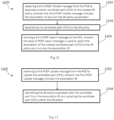
- Fig 3 illustrates PCEP messages communicated between a PCE and PCC, where the PCE may be a PCE 130 shown in Fig. 1 and the PCC may be a node 112 shown in Fig. 1 .
- the central control instructions may include the SR policy parameters. No candidate paths instantiation takes place in this step.
- the PCC 112 receives the first PCEP initiate message from the PCE 130, creates the SR policy using the SR policy parameters where the SR policy is a container independent of any candidate path.
- steps 302 and step 304 are proposed in the present disclosure and are not present in the existing Internet Drafts as prior to this disclosure the creating of SR policy independent of the candidate path(s) was not known.
- the PCE 130 sends a second PCEP initiate message, PCInitiate, to the PCC 112.
- the second PCEP message is for creating a new candidate path (CP1) and includes an Association object for associating the candidate path to the created SR policy.
- the Association object includes the set of SR policy parameters and the SR Policy association identifier (Association ID) corresponding to the SR policy.
- the PCC 112 sends a second PCEP report message, PCRpt, back to the PCE 130 to report the newly created candidate path (CP1) and includes the Association ID corresponding to the SR policy.
- the PCE 130 sends a PCEP update message, PCUpd, to the PCC 112.
- the update message is to update an existing candidate path (CP2).
- the PCEP update message includes the Association ID, referred to as SR policy association.
- FIG. 3 The illustration provided in Fig. 3 is only for providing clarity on the new CCI for creating SR policy independent of candidate paths, in comparison to existing Internet Drafts and does not limit the claimed invention in any manner.
- the concept of Association object and associating a new candidate path to a created SR Policy is known and therefore not discussed in detail henceforth.
- Fig. 4 illustrates a method 400 performed by a Path Computation Element (PCE) using a Path Computation Element Protocol (PCEP).
- the PCE herein may refer to a PCE 130 which may act upon the instructions of a Central Controller or act as a PCECC which has been discussed in Fig .1 .
- the PCE may also be one of the nodes 112 acting upon the instructions of a central controller. In present embodiments, the PCE acts as a PCECC.
- the method 400 includes step 402 where the PCE sends a first PCEP initiate message to a PCC, which may be a node 112 as described in Fig .1
- the first PCEP initiate message comprises a Central Controller Instruction (CCI) with a Central Controller Identifier (CC-ID) (X) for creating a Segment Routing (SR) policy.
- CCI Central Controller Instruction
- CC-ID Central Controller Identifier
- SR Segment Routing
- the step 402 may be considered equivalent to step 302 illustrated in Fig 3 and described above.
- the method 400 includes step 404 where the PCE receives a first PCEP report message from the PCC upon creation of the SR policy, wherein the first PCEP report message is used to report by the PCC that the SR policy corresponding to the CC-ID (X) has been created.
- the step 404 may be considered equivalent to step 304 illustrated in Fig. 3 and described above.
- Upon creating the SR policy as a separate container one or more candidate paths may be associated to the SR policy already created.
- One of the key advantages of creating a SR policy as a separate container is that even when the candidate path(s) go down in a network, the SR policy necessarily is not deleted and is retained.
- Fig. 5 illustrates a method 500 of creating a candidate path (CP1) in accordance with an embodiment of the present invention where the SR policy has been previously created at the PCC, the method 500 being performed by the PCE referred to in Fig. 4 .
- the method 500 includes a step 502 where the PCE sends to the PCC, a second PCEP initiate message to associate a candidate path (CP1) to the created SR policy, wherein the second PCEP initiate message includes a set of SR policy parameters and a SR Policy association identifier (Association ID) corresponding to the SR policy.
- the step 502 can be considered equivalent to step 306 illustrated in Fig. 3 and described above.
- the method includes step 504 where the PCE receives from the PCE a second PCEP report message wherein the second PCEP report message is used to report the association of the created candidate path (CP1) to the SR policy and the second PCEP report message includes the Association ID corresponding to the SR policy.
- the method of creating a candidate path initiated at the PCE is known from the teachings of the Internet Draft "draft-ietf-pce-segment-routing-policy-cp-00".
- the step 504 can be considered equivalent to step 308 illustrated in Fig. 3 and described above.
- the present disclosure is differentiated from said Internet Draft, as the SR policy is separate created in the method 400, and the candidate path is now created and associated to the SR policy through the Association ID. Whereas, in the prior solution the candidate path was created along with sharing the SR policy parameters and the PCE did not known whether the SR policy exists or has to be created. Thus, one of the key advantages of creating the SR policy as a separate container and then associating candidate path(s) does not require to process at the PCE whether the SR policy exists or has to be created.
- Fig. 6 illustrates a method 600 of creating another candidate path (CP2) in accordance with an embodiment of the present invention where the SR policy has been previously created at the PCC, the method 600 being performed by the PCE referred to in Fig. 4 and Fig. 5 . Also by saying another candidate path (CP2) it is assumed that previous candidate path (CP1) exists. Both, the previous candidate path (CP1) and the another candidate path (CP2) are for the same SR policy created as disclosed with respect to method 400 above.
- the method 600 includes at step 602 sending a third PCEP initiate message to the PCC to associate another candidate path (CP2) to the created SR policy, wherein the third PCEP initiate message includes the Association ID and not the SR policy parameters.
- the advantage associated with this step is that after the set of SR policy parameters are shared for a candidate path (CP 1) created for the first time and associated with the SR policy, they necessarily are not required to be shared again for the other candidate paths to be associated to the same SR policy.
- the Association ID is sent from the PCE to the PCC.
- the PCC uses the association ID to associate the candidate path (CP2) to the created SR policy.
- the PCE receives a receiving a third PCEP report message from the PCC, wherein the second PCEP report message is used to report the association of the created candidate path (CP2) to the SR policy and includes the Association ID.
- the above described methods 400 and 500 further include a method 700 to update an existing candidate path.
- An existing candidate path can be updated without sharing the set of SR policy parameters by sharing only the Association ID to the existing SR policy already created.
- the PCE sends a PCEP update message includes sending a PCEP update message to the PCC to update the candidate path (CP1), wherein the PCEP update message includes the Association ID.
- the method 700 can be considered equivalent to step 310 illustrated in Fig. 3 and described above.
- the method 700 may further include receiving an acknowledgement from the PCC (PCRpt) upon updating the candidate path with the SR policy association.
- Fig. 8 illustrates a method 800 performed by the PCE wherein the PCE sends sending a fourth PCEP initiate message to the PCC wherein the fourth PCEP initiate message to delete the SR policy and the fourth PCEP initiate message includes the CC-ID (X).
- Fig. 9 illustrates a method 900 performed by a Path Computation Client (PCC) using a Path Computation Element Protocol (PCEP).
- the PCC herein may refer to a node 112 as discussed in Fig. 1 .
- the PCC is in communication with a PCE which may act upon the instructions of a Central Controller or act as a PCECC which has been discussed in Fig .1 .
- the PCE herein refers to the PCE that performs the methods 400, 500, 600, 700 and 800.
- the method 900 includes step 902 where the PCC receives a first PCEP initiate message from a PCE.
- the first PCEP initiate message comprises a Central Controller Instruction (CCI) with a Central Controller Identifier (CC-ID) (X) for creating a Segment Routing (SR) policy.
- CCI Central Controller Instruction
- CC-ID Central Controller Identifier
- SR Segment Routing
- the step 902 may be considered equivalent to step 302 illustrated in Fig 3 and described above.
- the method 900 includes step 904 where the PCC sends a first PCEP report message to the PCE upon creation of the SR policy, wherein the first PCEP report message is used to report by the PCC that the SR policy corresponding to the CC-ID (X) has been created.
- step 904 may be considered equivalent to step 304 illustrated in Fig. 3 and described above.
- one or more candidate paths may be associated to the SR policy already created.
- One of the key advantages of creating a SR policy as a separate container is that even when the candidate path(s) go down in a network, the SR policy necessarily is not deleted and is retained.
- Fig. 10 illustrates a method 1000 of creating a candidate path (CP1) in accordance with an embodiment of the present invention where the SR policy has been previously created at the PCC, the method 1000 being performed by the PCC referred to in Fig. 9 .
- the method 1000 includes a step 1002 where the PCC receives from the PCE, a second PCEP initiate message to associate a candidate path (CP1) to the created SR policy, wherein the second PCEP initiate message includes a set of SR policy parameters and a SR Policy association identifier (Association ID) corresponding to the SR policy.
- the step 1002 can be considered equivalent to step 306 illustrated in Fig. 3 and described above.
- the method includes a step 1003 where the PCC associates the candidate path (CP1) to the created SR policy. Further, the method includes step 1004 where the PCC sends to the PCE a second PCEP report message wherein the second PCEP report message is used to report the association of the created candidate path (CP1) to the SR policy and the second PCEP report message includes the Association ID corresponding to the SR policy.
- the PCC sends to the PCE a second PCEP report message wherein the second PCEP report message is used to report the association of the created candidate path (CP1) to the SR policy and the second PCEP report message includes the Association ID corresponding to the SR policy.
- Fig. 11 illustrates a method 1100 of creating another candidate path (CP2) in accordance with an embodiment of the present invention where the SR policy has been previously created at the PCC, the method 1100 being performed by the PCC referred to in Fig. 9 and Fig. 10 . Also by saying another candidate path (CP2) it is assumed that previous candidate path (CP1) exists. Both, the previous candidate path (CP1) and the another candidate path (CP2) are for the same SR policy created as disclosed with respect to method 900 above.
- the method 1100 includes at step 1102 of receiving a third PCEP initiate message from the PCE to associate another candidate path (CP2) to the created SR policy, wherein the third PCEP initiate message includes the Association ID and not the SR policy parameters.
- the advantage associated with this step is that after the set of SR policy parameters are shared for a candidate path (CP1) created for the first time and associated with the SR policy, they necessarily are not required to be shared again for the other candidate paths to be associated to the same SR policy.
- the Association ID is sent from the PCE to the PCC.
- the method includes a step 1103 where the PCC associates the another candidate path (CP2) to the created SR policy.
- the PCC uses the association ID to associate the candidate path (CP2) to the created SR policy.
- the PCC sends a third PCEP report message to the PCE, wherein the second PCEP report message is used to report the association of the created candidate path (CP2) to the SR policy and includes the Association ID.
- the above described methods 900 and 1000 further include a method 1200 to update an existing candidate path.
- An existing candidate path can be updated without sharing the set of SR policy parameters by sharing only the Association ID to the existing SR policy already created.
- the PCC receives a PCEP update message from the PCE to update the candidate path (CP1), wherein the PCEP update message includes the Association ID.
- the method 1202 can be considered equivalent to step 310 illustrated in Fig. 3 and described above.
- the method 1200 may further include sending an acknowledgement by the PCC (PCRpt) to the PCE upon updating the candidate path with the SR policy association.
- the illustrated method 1200 may also include at step 1204, identifying, by the PCC, the SR policy associated with the candidate path from the Association ID and updating the candidate path (CP1) within the SR policy.
- Fig. 1300 illustrates a method 1300 performed by the PCC wherein the PCC receives a fourth PCEP initiate message from the PCE wherein the fourth PCEP initiate message is to delete the SR policy and the fourth PCEP initiate message includes the CC-ID (X).
- both the PCE and the PCC must indicate its support of the function described in this disclosure, i.e., the ability to support creation of a SR policy independent of a candidate path. This is done, by advertising to each other a defined capability TLV in an OPEN object.
- OPEN object The definition of such OPEN object is known in PCECC extensions and is not described in detail.
- the method performed by the PCE may include advertising to the PCC in an open PCEP message to indicate that the PCE supports CCI for creating SR policy independent of candidate path, wherein the advertising is prior to sending the first PCEP initiate message.
- the method performed by the PCC may include advertising to the PCE in an open PCEP message to indicate that the PCC supports CCI for creating SR policy independent of candidate path, wherein the advertising is prior to receiving the first PCEP initiate message.
- the apparatus and the system to support CCI for creating an SR policy independent of a candidate path is disclosed in the present invention.
- a Path Computation Element (PCE) 1400 that performs based on a Path Computation Element Protocol (PCEP) is illustrated, in accordance with an embodiment of the present disclosure.
- the PCE herein may refer to a PCE 130 which may act upon the instructions of a Central Controller or act as a PCECC which has been discussed in Fig .1 .
- the PCE may also be one of the nodes 112 acting upon the instructions of a central controller.
- the PCE acts as a PCECC.
- the present disclosure is explained considering that the elements shown in Fig. 14 , it may be understood that the PCE 1400 may include the elements and the functionalities disclosed for a node 200 disclosed in Fig. 2 .
- the PCE 1400 communicates with a Path Computation Client (PCC) using PCEP.
- the PCE 1400 includes a memory 1402 and a transceiver 1402.
- the memory 1402 shall be hereinafter referred to as the first memory 1402
- the transceiver 1402 shall be hereinafter referred to as the first transceiver 1404.
- the PCE 1400 may include a processor (not shown in Fig. 14 ), as shown for the node 200 in Fig.2 , which may be referred to as the first processor.
- the first memory 1402 and the first transceiver 1404 may be considered the same as the memory 240 and the transceiver 210 respectively, as explained above with respect to the node 200 of Fig 2 .
- the PCE 1400 is configured to perform the methods 400, 500, 600, 700 and 800 described above.
- the first memory 1402 is configured to store a PCEP object for a Central Controller Instruction (CCI) with a Central Controller Identifier (CC-ID) (X) for creating a Segment Routing (SR) policy.
- CCI Central Controller Instruction
- CC-ID Central Controller Identifier
- SR Segment Routing
- the first transceiver 1404 is configured to sends a first PCEP initiate message to a PCC, which may be a node 112 as described in Fig .1
- the first PCEP initiate message comprises the CCI) with the CC-ID (X) for creating a Segment Routing (SR) policy, and a set of parameters for the SR policy.
- the transceiver 1404 is configured to receive a first PCEP report message from the PCC upon creation of the SR policy, wherein the first PCEP report message is used to report by the PCC that the SR policy corresponding to the CC-ID (X) and the set of SR policy parameters has been created.
- the PCE is distinguished from the prior art as it supports creation of a SR policy independent of a candidate path.
- One of the key advantages of creating a SR policy as a separate container is that even when the candidate path(s) go down in a network, the SR policy necessarily is not deleted and is retained.
- first transceiver 1404 is configured to perform the functionalities disclosed with respect to the methods 500-800 disclosed in detail above and therefore the same is not repeated herein.
- the corresponding PCC which creates the SR policy upon instantiation by the PCE 1400 is illustrated in Fig. 15 .
- a Path Computation Client (PCC) 1500 that performs based on a Path Computation Element Protocol (PCEP) is illustrated, in accordance with an embodiment of the present disclosure.
- the PCC herein may refer to a node 112 which has been discussed in Fig .1 .
- the PCC 1500 may include the elements and the functionalities disclosed for a node 200 disclosed in Fig. 2 .
- the PCE 1500 communicates with the PCE 1400 using PCEP.
- the PCE 1500 includes a second memory 1502, a second transceiver 1504 and a second processor 1506.
- PCC 1500 The phrase 'second' used for the elements of PCC 1500 is for the sake of clarity and to distinguish the elements of the PCC 1500 from that of PCE 1400 in the present disclosure.
- the second memory 1502, the second transceiver 1504, and the second processor 1506 may be considered the same as the memory 240, the transceiver 210 and the processor 230 respectively, as explained above with respect to the node 200 of Fig 2 .
- the PCE 1500 is configured to perform the methods 900, 1000, 1100, 1200 and 1300 described above.
- the second memory 1502 is configured to store a first list and a second list.
- the first list includes one or more segment routing (SR) policies created at the PCC independent of the candidate paths and the second list includes a one or more candidate paths and a respective SR policy Association Identifier for each of the one or more candidate paths, the SR policy Association Identifier corresponding to a SR policy in the first list.
- the second transceiver 1504 is configured to receive a first PCEP initiate message from the PCE 1400 wherein the first PCEP initiate message comprises a Central Controller Instruction (CCI) with a Central Controller Identifier (CC-ID) (X) for creating a Segment Routing (SR) policy and a set of parameters for the SR policy.
- the second processor 1506 is configured to create the SR policy and store the SR policy in the first list.
- the second transceiver 1504 Upon creation of the SR policy, the second transceiver 1504 is configured to sends a first PCEP report message to the PCE, wherein the first PCEP report message is used to report by the PCC that the SR policy corresponding to the CC-ID (X) and the set of SR policy parameters has been created.
- the PCC is distinguished from the prior art as it supports creation of a SR policy independent of a candidate path.
- One of the key advantages of creating a SR policy as a separate container is that even when the candidate path(s) go down in a network, the SR policy necessarily is not deleted and is retained.
- the second transceiver 1504 is configured to perform the functionalities disclosed with respect to the methods 1000-1300 disclosed in detail above and therefore the same is not repeated herein.
- the second processor 1506 Upon receipt of the second PCEP initiate message at the PCC, the second processor 1506 is configured to associate the candidate path (CP1) with the Association ID in the second list. Further, upon receipt of the PCEP update message at the PCC, the second processor 1506 is configured to identify the SR policy associated with the candidate path from the Association ID and update the candidate path (CP1) within the SR policy. Further, upon receipt of the third PCEP initiate message the sending processor 1506 is configured to associate the candidate path (CP2) with the Association ID in the second list.
- the second processor 1506 upon receipt of the fourth PCEP initiate message at the PCC, the second processor 1506 is configured to delete the SR policy from the first list. Further, upon receipt of the third PCEP initiate message the second processor 1506 is configured to associate the candidate path (CP2) with the Association ID in the second list.
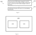
- a system 1600 comprising a PCE 1602 and a PCC 1604 in communication with each other using PCEP.
- the PCE 1602 includes the PCE 1400 disclosed with respect to Fig. 14 and the PCC 1604 includes the PCC 1500 disclosed with respect to Fig. 15 .
- the PCE 1602 and the PCC 1604 includes the node 200 disclosed with respect to Fig. 2 .
- the PCE 1602 includes the PCE 130 disclosed with respect to Fig. 1 and the PCC includes a node 112 disclosed with respect to Fig. 1 .
- the system 1600 implements the method disclosed in Fig.
- the functionalities of the PCE 1602 are already defined with respect to PCE 1400 and the functionalities of the PCC 1604 are already defined with respect to PCC 1500.
- the PCE 1602 includes a first memory 1402 that is configured to store a PCEP object for a Central Controller Instruction (CCI) with a Central Controller Identifier (CC-ID) (X) for creating a Segment Routing (SR) policy.
- the PCE includes a first transceiver that is configured to sends a first PCEP initiate message to the PCC 1604.
- the first PCEP initiate message comprises the CCI with the CC-ID (X) for creating a Segment Routing (SR) policy, and a set of parameters for the SR policy.
- the first transceiver is configured to receive a first PCEP report message from the PCC 1604 upon creation of the SR policy, wherein the first PCEP report message is used to report by the PCC that the SR policy corresponding to the CC-ID (X) and the set of SR policy parameters has been created.
- the PCC 1604 comprises a second memory and a second transceiver.
- the second memory is configured to store a first list and a second list.
- the first list includes one or more segment routing (SR) policies created at the PCC independent of the candidate paths and the second list includes a one or more candidate paths and a respective SR policy Association Identifier for each of the one or more candidate paths, the SR policy Association Identifier corresponding to a SR policy in the first list.
- the second transceiver is configured to receive the first PCEP initiate message from the PCE 1602 and to send the first PCEP report message to the PCE upon creation of the SR policy and to send the first PCEP report message to the PCE upon creation of the SR policy.
- the PCC 1604 also includes a second processor configured to create the SR policy and store the SR policy in the first list.
- the system 1600 including the PCE 1602 and the PCC 1604 distinguished from the prior art as it supports creation of a SR policy independent of a candidate path.
- One of the key advantages of creating a SR policy as a separate container is that even when the candidate path(s) go down in a network, the SR policy necessarily is not deleted and is retained.
- the first transceiver of the PCE 1602 is configured to perform the functionalities disclosed with respect to the first transceiver 1404 of the PCE 1400.
- the second transceiver and the second processor are configured to perform the functionalities of the second transceiver 1504 and the second processor 1506, respectively, of the PCC 1500.
Landscapes
- Engineering & Computer Science (AREA)
- Computer Networks & Wireless Communication (AREA)
- Signal Processing (AREA)
- Data Exchanges In Wide-Area Networks (AREA)
Claims (14)
- Verfahren, das durch ein Pfadberechnungselement, PCE, unter Verwendung eines Pfadberechnungselementprotokolls, PCEP, durchgeführt wird, umfassend:Bekanntmachen für einen Pfadberechnungsclient, PCC, in einer offenen PCEP-Nachricht, um anzugeben, dass das PCE eine Zentralsteuerungsanweisung, CCI, zum Erzeugen einer Segmentrouting-Richtlinie, SR-Richtlinie, unabhängig von einem in Frage kommenden Pfad unterstützt,Senden (402) einer ersten PCEP-Initiierungsnachricht an den PCC, wobei die erste PCEP-Initiierungsnachricht Folgendes umfasst:die CCI mit einer Zentralsteuerungskennung, CC-ID, zum Erzeugen der SR-Richtlinie;Empfangen (404) einer ersten PCEP-Meldenachricht von dem PCC bei der Erzeugung der SR-Richtlinie, wobei die erste PCEP-Meldenachricht verwendet wird, um durch den PCC zu melden, dass die SR-Richtlinie, die der CC-ID entspricht, erzeugt worden ist.
- Verfahren nach Anspruch 1, ferner umfassend:Senden (502) einer zweiten PCEP-Initiierungsnachricht an den PCC, um der erzeugten SR-Richtlinie einen in Frage kommenden Pfad zuzuordnen, wobei die zweite PCEP-Initiierungsnachricht einen Satz von SR-Richtlinienparametern und eine SR-Richtlinienzuordnungskennung, die der SR-Richtlinie entspricht, beinhaltet;Empfangen (504) einer zweiten PCEP-Meldenachricht von dem PCC, wobei die zweite PCEP-Meldenachricht verwendet wird, um eine Zuordnung des erzeugten in Frage kommenden Pfads zu der SR-Richtlinie zu melden, und die zweite PCEP-Meldenachricht die Zuordnungs-ID, die der SR-Richtlinie entspricht, beinhaltet.
- Verfahren nach Anspruch 2, umfassend Senden einer PCEP-Aktualisierungsnachricht an den PCC, um den in Frage kommenden Pfad zu aktualisieren, wobei die PCEP-Aktualisierungsnachricht die Zuordnungs-ID beinhaltet.
- Verfahren nach Anspruch 2, umfassend:Senden (602) einer dritten PCEP-Initiierungsnachricht an den PCC, um der erzeugten SR-Richtlinie einen anderen in Frage kommenden Pfad zuzuordnen, wobei die dritte PCEP-Initiierungsnachricht die Zuordnungs-ID und nicht die SR-Richtlinienparameter beinhaltet;Empfangen (604) einer dritten PCEP-Meldenachricht von dem PCC, wobei die dritte PCEP-Meldenachricht verwendet wird, um eine Zuordnung des erzeugten in Frage kommenden Pfads zu der SR-Richtlinie zu melden, und die dritte PCEP-Meldenachricht die Zuordnungs-ID, die der SR-Richtlinie entspricht, beinhaltet.
- Verfahren nach Anspruch 1, umfassend:
Senden einer vierten PCEP-Initiierungsnachricht an den PCC, wobei die vierte PCEP-Initiierungsnachricht zum Löschen der SR-Richtlinie dient und die vierte PCEP-Initiierungsnachricht die CC-ID beinhaltet. - Verfahren nach Anspruch 1, wobei die erste PCEP-Initiierungsnachricht ein Farbfeld, ein Headend-Feld und ein Endpunktfeld, die SR-Richtlinienparameter sind, beinhaltet, wobei das Farbfeld eine vorzeichenlose 32-Bit-Zahl ist und das Headend-Feld und das Endpunktfeld jeweils IPv4-Adressen oder IPv6-Adressen basierend auf dem CCI-Objekttyp sind; und
ein optionaler TLV den Informationen entspricht, die zum Kodieren von "SRPOLICY-POL-NAME TLV" verwendet werden, der einen Namen der SR-Richtlinie definiert. - Verfahren nach Anspruch 1, wobei das PCE als eine PCE-Zentralsteuerung, PCECC, fungiert.
- Verfahren, das durch einen Pfadberechnungsclient, PCC, unter Verwendung eines Pfadberechnungselementprotokolls, PCEP, durchgeführt wird, umfassend:Empfangen einer Bekanntmachung von einem Pfadberechnungselement, PCE, in einer offenen PCEP-Nachricht, um anzugeben, dass das PCE eine Zentralsteuerungsanweisung, CCI, zum Erzeugen einer Segmentrouting-Richtlinie, SR-Richtlinie, unabhängig von einem in Frage kommenden Pfad unterstützt.Empfangen (902) einer ersten PCEP-Initiierungsnachricht von dem PCE, wobei die erste PCEP-Initiierungsnachricht, die von dem PCE empfangen wird, Folgendes umfasst:die CCI mit einer Zentralsteuerungskennung, CC-ID, zum Erzeugen der SR-Richtlinie;Senden (904) einer ersten PCEP-Meldenachricht an das PCE bei der Erzeugung der SR-Richtlinie, wobei die erste PCEP-Meldenachricht verwendet wird, um durch den PCC zu melden, dass die SR-Richtlinie, die der CC-ID entspricht, erzeugt worden ist.
- Verfahren nach Anspruch 8, ferner umfassend:Empfangen (1002) einer zweiten PCEP-Initiierungsnachricht von dem PCE, um der erzeugten SR-Richtlinie einen in Frage kommenden Pfad zuzuordnen, wobei die zweite PCEP-Initiierungsnachricht einen Satz von SR-Richtlinienparametern und eine SR-Richtlinienzuordnungskennung, Zuordnungs-ID, die der SR-Richtlinie entspricht, beinhaltet;Zuordnen (1003) des in Frage kommenden Pfads zu der erzeugten SR-Richtlinie;Senden (1004) einer zweiten PCEP-Meldenachricht an das PCE, wobei die zweite PCEP-Meldenachricht verwendet wird, um eine Zuordnung des erzeugten in Frage kommenden Pfads zu der SR-Richtlinie zu melden, und die zweite PCEP-Meldenachricht die Zuordnungs-ID, die der SR-Richtlinie entspricht, beinhaltet.
- Verfahren nach Anspruch 9, umfassend:Empfangen einer PCEP-Aktualisierungsnachricht von dem PCE, um den in Frage kommenden Pfad zu aktualisieren, wobei die PCEP-Aktualisierungsnachricht die Zuordnungs-ID beinhaltet; undIdentifizieren der SR-Richtlinie, die dem in Frage kommenden Pfad zugeordnet ist, aus der Zuordnungs-ID und Aktualisieren des in Frage kommenden Pfads innerhalb der SR-Richtlinie.
- Verfahren nach Anspruch 9, umfassend:Empfangen (1102) einer dritten PCEP-Initiierungsnachricht von dem PCE, um der erzeugten SR-Richtlinie einen anderen in Frage kommenden Pfad zuzuordnen, wobei die dritte PCEP-Initiierungsnachricht die Zuordnungs-ID und nicht die SR-Richtlinienparameter beinhaltet;Zuordnen (1103) des anderen in Frage kommenden Pfads zu der erzeugten SR-Richtlinie;Senden (1104) einer dritten PCEP-Meldenachricht an das PCE, wobei die dritte PCEP-Meldenachricht verwendet wird, um eine Zuordnung des erzeugten in Frage kommenden Pfads zu der SR-Richtlinie zu melden, und die dritte PCEP-Meldenachricht die Zuordnungs-ID, die der SR-Richtlinie entspricht, beinhaltet.
- Verfahren nach Anspruch 8, umfassend:Empfangen einer vierten PCEP-Initiierungsnachricht von dem PCE, wobei die vierte PCEP-Initiierungsnachricht zum Löschen der SR-Richtlinie dient und die vierte PCEP-Initiierungsnachricht die CC-ID beinhaltet;Identifizieren der SR-Richtlinie aus der CC-ID und Löschen der SR-Richtlinie.
- Pfadberechnungselement, PCE, das ein Pfadberechnungselementprotokoll, PCEP, verwendet, wobei das PCE dazu konfiguriert ist, das Verfahren nach einem der Ansprüche 1 bis 7 durchzuführen.
- Pfadberechnungsclient, der ein Pfadberechnungselementprotokoll, PCEP, verwendet, wobei der PCC dazu konfiguriert ist, das Verfahren nach einem der Ansprüche 8 bis 12 durchzuführen.
Applications Claiming Priority (2)
| Application Number | Priority Date | Filing Date | Title |
|---|---|---|---|
| IN202031055293 | 2020-12-18 | ||
| PCT/CN2021/139782 WO2022127936A1 (en) | 2020-12-18 | 2021-12-20 | Methods, apparatus and system for creating sr policy using path computation element protocol |
Publications (3)
| Publication Number | Publication Date |
|---|---|
| EP4252399A1 EP4252399A1 (de) | 2023-10-04 |
| EP4252399A4 EP4252399A4 (de) | 2024-01-17 |
| EP4252399B1 true EP4252399B1 (de) | 2025-02-12 |
Family
ID=82058940
Family Applications (1)
| Application Number | Title | Priority Date | Filing Date |
|---|---|---|---|
| EP21905858.3A Active EP4252399B1 (de) | 2020-12-18 | 2021-12-20 | Verfahren, vorrichtung und system zur erzeugung einer sr-richtlinie unter verwendung eines pfadberechnungselementprotokolls |
Country Status (4)
| Country | Link |
|---|---|
| US (1) | US20230336471A1 (de) |
| EP (1) | EP4252399B1 (de) |
| CN (1) | CN116530065A (de) |
| WO (1) | WO2022127936A1 (de) |
Families Citing this family (5)
| Publication number | Priority date | Publication date | Assignee | Title |
|---|---|---|---|---|
| CN115665024A (zh) * | 2021-07-08 | 2023-01-31 | 中兴通讯股份有限公司 | 确定性流的转发方法及装置、存储介质及电子装置 |
| US12355770B2 (en) * | 2023-10-03 | 2025-07-08 | strongDM, Inc. | Identity and activity based network security policies |
| US12242599B1 (en) | 2024-09-27 | 2025-03-04 | strongDM, Inc. | Fine-grained security policy enforcement for applications |
| US12348519B1 (en) | 2025-02-07 | 2025-07-01 | strongDM, Inc. | Evaluating security policies in aggregate |
| US12432242B1 (en) | 2025-03-28 | 2025-09-30 | strongDM, Inc. | Anomaly detection in managed networks |
Family Cites Families (11)
| Publication number | Priority date | Publication date | Assignee | Title |
|---|---|---|---|---|
| US9537753B2 (en) * | 2014-03-03 | 2017-01-03 | Cisco Technology, Inc. | Opaque profile identifiers for path computation element protocol |
| CN111726294B (zh) * | 2015-10-16 | 2024-07-26 | 华为技术有限公司 | 流规则发送的方法、路径计算单元和路径计算客户端 |
| US10581723B2 (en) * | 2016-04-01 | 2020-03-03 | Futurewei Technologies, Inc. | PCEP extension for PCECC support of distributed computing, multiple services, and inter-domain routing |
| CN109076014A (zh) * | 2016-05-03 | 2018-12-21 | 华为技术有限公司 | 分组交换通信网络中的标签数据库同步 |
| US10212088B2 (en) * | 2016-11-07 | 2019-02-19 | Cisco Technology, Inc. | Tactical traffic engineering based on segment routing policies |
| KR102315401B1 (ko) * | 2017-07-14 | 2021-10-19 | 후아웨이 테크놀러지 컴퍼니 리미티드 | Ipv6 터널에 대한 세그먼트 라우팅을 구축하기 위한 방법 |
| CN110061920B (zh) * | 2018-01-18 | 2021-10-19 | 中兴通讯股份有限公司 | 一种创建双向段路由隧道的方法、设备及存储介质 |
| US10812374B2 (en) * | 2018-09-21 | 2020-10-20 | Cisco Technology, Inc. | Segment routing with fast reroute for container networking |
| JP7176428B2 (ja) * | 2019-02-06 | 2022-11-22 | 日本電信電話株式会社 | 制御装置、制御方法及びプログラム |
| CN112054958B (zh) * | 2019-06-06 | 2023-07-14 | 中兴通讯股份有限公司 | 路径计算方法及存储介质、电子装置 |
| CN111917643B (zh) * | 2020-07-17 | 2023-01-13 | 中盈优创资讯科技有限公司 | 分段路由隧道的无缝双向转发检测方法及装置 |
-
2021
- 2021-12-20 WO PCT/CN2021/139782 patent/WO2022127936A1/en not_active Ceased
- 2021-12-20 CN CN202180081189.XA patent/CN116530065A/zh active Pending
- 2021-12-20 EP EP21905858.3A patent/EP4252399B1/de active Active
-
2023
- 2023-06-16 US US18/336,058 patent/US20230336471A1/en not_active Abandoned
Also Published As
| Publication number | Publication date |
|---|---|
| EP4252399A1 (de) | 2023-10-04 |
| EP4252399A4 (de) | 2024-01-17 |
| WO2022127936A1 (en) | 2022-06-23 |
| US20230336471A1 (en) | 2023-10-19 |
| CN116530065A (zh) | 2023-08-01 |
Similar Documents
| Publication | Publication Date | Title |
|---|---|---|
| US11962496B2 (en) | Method for establishing segment routing for IPv6 tunnel | |
| EP4252399B1 (de) | Verfahren, vorrichtung und system zur erzeugung einer sr-richtlinie unter verwendung eines pfadberechnungselementprotokolls | |
| US10855582B2 (en) | Using PCE as SDN controller | |
| US11943136B2 (en) | Advanced preferred path route graph features in a network | |
| US9231851B2 (en) | System and method for computing point-to-point label switched path crossing multiple domains | |
| CN111865796B (zh) | 用于网络业务的路径计算单元中央控制器(pcecc) | |
| CN102771096B (zh) | 用于计算点到多点标签交换路径的备份入节点的系统和方法 | |
| US11431630B2 (en) | Method and apparatus for preferred path route information distribution and maintenance | |
| CN109314663B (zh) | Pcep扩展用于支持分布式计算、多项服务和域间路由的pcecc | |
| US20160006614A1 (en) | Source Routing Using Path Computation Elements | |
| US9992105B2 (en) | Label switched path reporting | |
| EP2933958A1 (de) | Segment-routing - egress-peer-engineering (sp-epe) | |
| US7852840B2 (en) | Method and device for creating a tunnel in a label-switched telecommunication network | |
| CN101047651B (zh) | 设置ip优先级的方法、系统和设备 | |
| WO2019007390A1 (en) | EPC SEGMENT ROUTING PATH SEGMENT LABEL LINK EXTENSION | |
| US11632322B2 (en) | Preferred path route graphs in a network | |
| US20210051092A1 (en) | Explicit Backups and Fast Re-Route Mechanisms For Preferred Path Routes in a Network | |
| US11611447B2 (en) | Multicast (P2MP) support for path computation element central controller (PCECC) | |
| US20140269737A1 (en) | System, method and apparatus for lsp setup using inter-domain abr indication |
Legal Events
| Date | Code | Title | Description |
|---|---|---|---|
| STAA | Information on the status of an ep patent application or granted ep patent |
Free format text: STATUS: THE INTERNATIONAL PUBLICATION HAS BEEN MADE |
|
| PUAI | Public reference made under article 153(3) epc to a published international application that has entered the european phase |
Free format text: ORIGINAL CODE: 0009012 |
|
| STAA | Information on the status of an ep patent application or granted ep patent |
Free format text: STATUS: REQUEST FOR EXAMINATION WAS MADE |
|
| 17P | Request for examination filed |
Effective date: 20230627 |
|
| AK | Designated contracting states |
Kind code of ref document: A1 Designated state(s): AL AT BE BG CH CY CZ DE DK EE ES FI FR GB GR HR HU IE IS IT LI LT LU LV MC MK MT NL NO PL PT RO RS SE SI SK SM TR |
|
| A4 | Supplementary search report drawn up and despatched |
Effective date: 20231215 |
|
| RIC1 | Information provided on ipc code assigned before grant |
Ipc: H04L 45/42 20220101ALI20231211BHEP Ipc: H04L 45/24 20220101AFI20231211BHEP |
|
| DAV | Request for validation of the european patent (deleted) | ||
| DAX | Request for extension of the european patent (deleted) | ||
| GRAP | Despatch of communication of intention to grant a patent |
Free format text: ORIGINAL CODE: EPIDOSNIGR1 |
|
| STAA | Information on the status of an ep patent application or granted ep patent |
Free format text: STATUS: GRANT OF PATENT IS INTENDED |
|
| INTG | Intention to grant announced |
Effective date: 20240826 |
|
| GRAS | Grant fee paid |
Free format text: ORIGINAL CODE: EPIDOSNIGR3 |
|
| GRAA | (expected) grant |
Free format text: ORIGINAL CODE: 0009210 |
|
| STAA | Information on the status of an ep patent application or granted ep patent |
Free format text: STATUS: THE PATENT HAS BEEN GRANTED |
|
| AK | Designated contracting states |
Kind code of ref document: B1 Designated state(s): AL AT BE BG CH CY CZ DE DK EE ES FI FR GB GR HR HU IE IS IT LI LT LU LV MC MK MT NL NO PL PT RO RS SE SI SK SM TR |
|
| REG | Reference to a national code |
Ref country code: GB Ref legal event code: FG4D |
|
| REG | Reference to a national code |
Ref country code: CH Ref legal event code: EP |
|
| REG | Reference to a national code |
Ref country code: DE Ref legal event code: R096 Ref document number: 602021026195 Country of ref document: DE |
|
| REG | Reference to a national code |
Ref country code: IE Ref legal event code: FG4D |
|
| REG | Reference to a national code |
Ref country code: NL Ref legal event code: MP Effective date: 20250212 |
|
| PG25 | Lapsed in a contracting state [announced via postgrant information from national office to epo] |
Ref country code: RS Free format text: LAPSE BECAUSE OF FAILURE TO SUBMIT A TRANSLATION OF THE DESCRIPTION OR TO PAY THE FEE WITHIN THE PRESCRIBED TIME-LIMIT Effective date: 20250512 |
|
| PG25 | Lapsed in a contracting state [announced via postgrant information from national office to epo] |
Ref country code: FI Free format text: LAPSE BECAUSE OF FAILURE TO SUBMIT A TRANSLATION OF THE DESCRIPTION OR TO PAY THE FEE WITHIN THE PRESCRIBED TIME-LIMIT Effective date: 20250212 |
|
| PG25 | Lapsed in a contracting state [announced via postgrant information from national office to epo] |
Ref country code: PL Free format text: LAPSE BECAUSE OF FAILURE TO SUBMIT A TRANSLATION OF THE DESCRIPTION OR TO PAY THE FEE WITHIN THE PRESCRIBED TIME-LIMIT Effective date: 20250212 |
|
| PG25 | Lapsed in a contracting state [announced via postgrant information from national office to epo] |
Ref country code: ES Free format text: LAPSE BECAUSE OF FAILURE TO SUBMIT A TRANSLATION OF THE DESCRIPTION OR TO PAY THE FEE WITHIN THE PRESCRIBED TIME-LIMIT Effective date: 20250212 |
|
| REG | Reference to a national code |
Ref country code: LT Ref legal event code: MG9D |
|
| PG25 | Lapsed in a contracting state [announced via postgrant information from national office to epo] |
Ref country code: IS Free format text: LAPSE BECAUSE OF FAILURE TO SUBMIT A TRANSLATION OF THE DESCRIPTION OR TO PAY THE FEE WITHIN THE PRESCRIBED TIME-LIMIT Effective date: 20250612 Ref country code: NO Free format text: LAPSE BECAUSE OF FAILURE TO SUBMIT A TRANSLATION OF THE DESCRIPTION OR TO PAY THE FEE WITHIN THE PRESCRIBED TIME-LIMIT Effective date: 20250512 |
|
| PG25 | Lapsed in a contracting state [announced via postgrant information from national office to epo] |
Ref country code: NL Free format text: LAPSE BECAUSE OF FAILURE TO SUBMIT A TRANSLATION OF THE DESCRIPTION OR TO PAY THE FEE WITHIN THE PRESCRIBED TIME-LIMIT Effective date: 20250212 |
|
| PG25 | Lapsed in a contracting state [announced via postgrant information from national office to epo] |
Ref country code: HR Free format text: LAPSE BECAUSE OF FAILURE TO SUBMIT A TRANSLATION OF THE DESCRIPTION OR TO PAY THE FEE WITHIN THE PRESCRIBED TIME-LIMIT Effective date: 20250212 |
|
| PG25 | Lapsed in a contracting state [announced via postgrant information from national office to epo] |
Ref country code: LV Free format text: LAPSE BECAUSE OF FAILURE TO SUBMIT A TRANSLATION OF THE DESCRIPTION OR TO PAY THE FEE WITHIN THE PRESCRIBED TIME-LIMIT Effective date: 20250212 Ref country code: PT Free format text: LAPSE BECAUSE OF FAILURE TO SUBMIT A TRANSLATION OF THE DESCRIPTION OR TO PAY THE FEE WITHIN THE PRESCRIBED TIME-LIMIT Effective date: 20250612 |
|
| PG25 | Lapsed in a contracting state [announced via postgrant information from national office to epo] |
Ref country code: GR Free format text: LAPSE BECAUSE OF FAILURE TO SUBMIT A TRANSLATION OF THE DESCRIPTION OR TO PAY THE FEE WITHIN THE PRESCRIBED TIME-LIMIT Effective date: 20250513 Ref country code: BG Free format text: LAPSE BECAUSE OF FAILURE TO SUBMIT A TRANSLATION OF THE DESCRIPTION OR TO PAY THE FEE WITHIN THE PRESCRIBED TIME-LIMIT Effective date: 20250212 |
|
| REG | Reference to a national code |
Ref country code: AT Ref legal event code: MK05 Ref document number: 1767172 Country of ref document: AT Kind code of ref document: T Effective date: 20250212 |
|
| PG25 | Lapsed in a contracting state [announced via postgrant information from national office to epo] |
Ref country code: SE Free format text: LAPSE BECAUSE OF FAILURE TO SUBMIT A TRANSLATION OF THE DESCRIPTION OR TO PAY THE FEE WITHIN THE PRESCRIBED TIME-LIMIT Effective date: 20250212 |
|
| PG25 | Lapsed in a contracting state [announced via postgrant information from national office to epo] |
Ref country code: SM Free format text: LAPSE BECAUSE OF FAILURE TO SUBMIT A TRANSLATION OF THE DESCRIPTION OR TO PAY THE FEE WITHIN THE PRESCRIBED TIME-LIMIT Effective date: 20250212 |
|
| PG25 | Lapsed in a contracting state [announced via postgrant information from national office to epo] |
Ref country code: DK Free format text: LAPSE BECAUSE OF FAILURE TO SUBMIT A TRANSLATION OF THE DESCRIPTION OR TO PAY THE FEE WITHIN THE PRESCRIBED TIME-LIMIT Effective date: 20250212 |
|
| PG25 | Lapsed in a contracting state [announced via postgrant information from national office to epo] |
Ref country code: IT Free format text: LAPSE BECAUSE OF FAILURE TO SUBMIT A TRANSLATION OF THE DESCRIPTION OR TO PAY THE FEE WITHIN THE PRESCRIBED TIME-LIMIT Effective date: 20250212 |
|
| PG25 | Lapsed in a contracting state [announced via postgrant information from national office to epo] |
Ref country code: AT Free format text: LAPSE BECAUSE OF FAILURE TO SUBMIT A TRANSLATION OF THE DESCRIPTION OR TO PAY THE FEE WITHIN THE PRESCRIBED TIME-LIMIT Effective date: 20250212 |
|
| PG25 | Lapsed in a contracting state [announced via postgrant information from national office to epo] |
Ref country code: EE Free format text: LAPSE BECAUSE OF FAILURE TO SUBMIT A TRANSLATION OF THE DESCRIPTION OR TO PAY THE FEE WITHIN THE PRESCRIBED TIME-LIMIT Effective date: 20250212 Ref country code: CZ Free format text: LAPSE BECAUSE OF FAILURE TO SUBMIT A TRANSLATION OF THE DESCRIPTION OR TO PAY THE FEE WITHIN THE PRESCRIBED TIME-LIMIT Effective date: 20250212 |
|
| PG25 | Lapsed in a contracting state [announced via postgrant information from national office to epo] |
Ref country code: RO Free format text: LAPSE BECAUSE OF FAILURE TO SUBMIT A TRANSLATION OF THE DESCRIPTION OR TO PAY THE FEE WITHIN THE PRESCRIBED TIME-LIMIT Effective date: 20250212 |
|
| PG25 | Lapsed in a contracting state [announced via postgrant information from national office to epo] |
Ref country code: SK Free format text: LAPSE BECAUSE OF FAILURE TO SUBMIT A TRANSLATION OF THE DESCRIPTION OR TO PAY THE FEE WITHIN THE PRESCRIBED TIME-LIMIT Effective date: 20250212 |
|
| REG | Reference to a national code |
Ref country code: DE Ref legal event code: R097 Ref document number: 602021026195 Country of ref document: DE |
|
| PLBE | No opposition filed within time limit |
Free format text: ORIGINAL CODE: 0009261 |
|
| STAA | Information on the status of an ep patent application or granted ep patent |
Free format text: STATUS: NO OPPOSITION FILED WITHIN TIME LIMIT |
|
| PGFP | Annual fee paid to national office [announced via postgrant information from national office to epo] |
Ref country code: DE Payment date: 20251104 Year of fee payment: 5 |
|
| 26N | No opposition filed |
Effective date: 20251113 |