EP4251958B1 - Tank comprising a device for measuring the level of fluid, and corresponding measuring method - Google Patents
Tank comprising a device for measuring the level of fluid, and corresponding measuring method Download PDFInfo
- Publication number
- EP4251958B1 EP4251958B1 EP21834948.8A EP21834948A EP4251958B1 EP 4251958 B1 EP4251958 B1 EP 4251958B1 EP 21834948 A EP21834948 A EP 21834948A EP 4251958 B1 EP4251958 B1 EP 4251958B1
- Authority
- EP
- European Patent Office
- Prior art keywords
- level
- blade
- tank
- sensor
- fluid
- Prior art date
- Legal status (The legal status is an assumption and is not a legal conclusion. Google has not performed a legal analysis and makes no representation as to the accuracy of the status listed.)
- Active
Links
Images

Classifications
-
- G—PHYSICS
- G01—MEASURING; TESTING
- G01F—MEASURING VOLUME, VOLUME FLOW, MASS FLOW OR LIQUID LEVEL; METERING BY VOLUME
- G01F23/00—Indicating or measuring liquid level or level of fluent solid material, e.g. indicating in terms of volume or indicating by means of an alarm
- G01F23/30—Indicating or measuring liquid level or level of fluent solid material, e.g. indicating in terms of volume or indicating by means of an alarm by floats
- G01F23/32—Indicating or measuring liquid level or level of fluent solid material, e.g. indicating in terms of volume or indicating by means of an alarm by floats using rotatable arms or other pivotable transmission elements
- G01F23/36—Indicating or measuring liquid level or level of fluent solid material, e.g. indicating in terms of volume or indicating by means of an alarm by floats using rotatable arms or other pivotable transmission elements using electrically actuated indicating means
-
- B—PERFORMING OPERATIONS; TRANSPORTING
- B01—PHYSICAL OR CHEMICAL PROCESSES OR APPARATUS IN GENERAL
- B01F—MIXING, e.g. DISSOLVING, EMULSIFYING OR DISPERSING
- B01F27/00—Mixers with rotary stirring devices in fixed receptacles; Kneaders
- B01F27/05—Stirrers
- B01F27/11—Stirrers characterised by the configuration of the stirrers
- B01F27/112—Stirrers characterised by the configuration of the stirrers with arms, paddles, vanes or blades
-
- B—PERFORMING OPERATIONS; TRANSPORTING
- B01—PHYSICAL OR CHEMICAL PROCESSES OR APPARATUS IN GENERAL
- B01F—MIXING, e.g. DISSOLVING, EMULSIFYING OR DISPERSING
- B01F27/00—Mixers with rotary stirring devices in fixed receptacles; Kneaders
- B01F27/05—Stirrers
- B01F27/11—Stirrers characterised by the configuration of the stirrers
- B01F27/17—Stirrers with additional elements mounted on the stirrer, for purposes other than mixing
-
- B—PERFORMING OPERATIONS; TRANSPORTING
- B01—PHYSICAL OR CHEMICAL PROCESSES OR APPARATUS IN GENERAL
- B01F—MIXING, e.g. DISSOLVING, EMULSIFYING OR DISPERSING
- B01F35/00—Accessories for mixers; Auxiliary operations or auxiliary devices; Parts or details of general application
- B01F35/20—Measuring; Control or regulation
- B01F35/21—Measuring
- B01F35/211—Measuring of the operational parameters
- B01F35/2112—Level of material in a container or the position or shape of the upper surface of the material
-
- G—PHYSICS
- G01—MEASURING; TESTING
- G01F—MEASURING VOLUME, VOLUME FLOW, MASS FLOW OR LIQUID LEVEL; METERING BY VOLUME
- G01F23/00—Indicating or measuring liquid level or level of fluent solid material, e.g. indicating in terms of volume or indicating by means of an alarm
- G01F23/0007—Indicating or measuring liquid level or level of fluent solid material, e.g. indicating in terms of volume or indicating by means of an alarm for discrete indicating and measuring
-
- G—PHYSICS
- G01—MEASURING; TESTING
- G01F—MEASURING VOLUME, VOLUME FLOW, MASS FLOW OR LIQUID LEVEL; METERING BY VOLUME
- G01F23/00—Indicating or measuring liquid level or level of fluent solid material, e.g. indicating in terms of volume or indicating by means of an alarm
- G01F23/30—Indicating or measuring liquid level or level of fluent solid material, e.g. indicating in terms of volume or indicating by means of an alarm by floats
- G01F23/32—Indicating or measuring liquid level or level of fluent solid material, e.g. indicating in terms of volume or indicating by means of an alarm by floats using rotatable arms or other pivotable transmission elements
- G01F23/38—Indicating or measuring liquid level or level of fluent solid material, e.g. indicating in terms of volume or indicating by means of an alarm by floats using rotatable arms or other pivotable transmission elements using magnetically actuated indicating means
Definitions
- the present invention concerns a tank comprising a device for measuring the level of fluid contained therein.
- the present invention also concerns a method to measure the level of fluid in a tank by means of said measuring device.
- the tank can be a tank for containing fluid products such as coloring liquids, bases for paints, varnishes, enamels, inks and suchlike, suitable to be installed on machines for dispensing or distributing such fluid products.
- fluid products such as coloring liquids, bases for paints, varnishes, enamels, inks and suchlike, suitable to be installed on machines for dispensing or distributing such fluid products.
- the measuring device is able to detect at least one level of fluid in the tank, or at least a minimum level of fluid inside the tank.
- Machines for dispensing or distributing fluid products are known, such as dyes of different shades or colors, able to be mixed together and/or added to a base substance to make up a varnish or a paint of a determinate color.
- Known machines normally comprise a plurality of containers containing a determinate dye, which can be selectively connected to one or more delivery nozzles and associated with respective pump means which cause the selective delivery of the fluid product contained therein in a suitably selected quantity, for example with the aid of an electronic processor.
- Each container comprises inside it a stirring device, which can be selectively activated, able to prevent the heavier components present in the fluid from settling on the bottom of the container itself, with a consequent undesired drying of the fluid.
- the stirring device is also able to prevent the various components present in the fluid - typically characterized by different densities/viscosities - from separating, in order to prevent product degradation.
- the level is typically recorded manually by the user when filling the tank and then the software system to manage and control the machine keeps track of it, based on the subsequent dispensing of quantities that are made.
- the software system to manage and control the machine keeps track of it, based on the subsequent dispensing of quantities that are made.
- this system has obvious limits of potential misalignments between the actual value inside the tank and the "theoretical" value present in the system, mainly due to possible errors or oversights by the operator.
- a misalignment error regarding the theoretical and real quantity of dye in the tank can lead to dispensing being started, because the system believes there is enough product in the tank, when in reality there is not enough. This situation, which as of today cannot be intercepted and verifiable, creates an incorrect dispensing, which is naturally undesirable for the customer and end user, in terms of costs and the wrong quantity of product received.
- pressure sensors are used that detect the quantity of product inside the tank, since the specific weight of the product and the tare weight are known.
- This system has various limitations, including the high cost, the need for setting, the need to create a complex "floating" system able to be sensitive to pressure.
- WO 01/42014 A2 discloses a tank with a stirring device comprising stirring blades and a blade type level sensor mounted on the side of the tank, remotely from the stirring blades.
- one purpose of the present invention is to provide a device for measuring the level of fluid in a tank which is efficient, economical and can be applied in any type of tank and with any type of fluid present in the tank, in particular but not exclusively, coloring liquids, bases for paints, varnishes, enamels, inks and suchlike.
- Another purpose of the present invention is to provide a device for measuring the level of fluid in a tank in which the sensor able to detect the level of fluid, in particular when a certain level of fluid is reached, is not in direct contact with the fluid to be measured.
- Another purpose of the present invention is to provide a tank to contain a fluid product to which a device for measuring the level of fluid can be applied, irrespective of the shape and size of the tank and irrespective of the nature of the fluid contained.
- the Applicant has devised, tested and embodied the present invention to overcome the shortcomings of the state of the art and to obtain these and other purposes and advantages.
- a tank for containing a fluid comprises both one or more stirring blades able to rotate by means of corresponding drive means in order to stir the fluid contained in the tank, and also a device for measuring the level of fluid contained in the tank.
- the device for measuring the level of fluid comprises at least one mobile level blade positioned during use inside the tank, and at least one sensor configured to detect at least one position of the level blade and positioned during use outside the tank.
- the level blade is configured to interact with the sensor in order to determine the level of fluid in the tank in relation to a threshold level, in correspondence with which the sensor can preferably be positioned.
- the level blade is configured to alternatively assume a first operating configuration when the level of fluid in the tank is greater than or equal to the threshold level, and a second operating configuration when the level of fluid in the tank falls below such threshold level; the relative position between the level blade and the sensor thus varying in the passage from the first operating configuration to the second operating configuration, which allows to detect a variation of interaction between the level blade and the sensor, which is indicative of the lowering of the level of fluid below the threshold level.
- the level blade in the first operating configuration is disposed substantially vertically, while in the second embodiment it is disposed substantially horizontally or inclined by an angle smaller than about 60°, preferably approximately equal to 45°.
- the level blade can be provided with at least one magnet and the sensor can be a magnetic sensor; such magnet is positioned substantially at the same height as the sensor.
- the level blade can be made, in whole or in part, of metal material and the sensor can be an inductive sensor.
- the senor can be a capacitive sensor configured to detect the capacitance variation due to the movement of the level blade.
- the level blade can also comprise at least one sensor configured to measure its position.
- the level blade can be angularly pivoting around a pin, and comprise an upper part and a lower part with respect to the pin.
- the magnet if provided, will in this case be positioned on the upper part of the level blade.
- the level blade can pivot around the pin at least from a first substantially vertical position, in which the level of fluid is higher than the threshold level, to at least a second substantially horizontal or inclined position, in which the level of fluid is lower than the threshold level, or vice versa.
- the level blade is configured to angularly pivot freely around the pin, since it is mounted idle on the latter.
- the level blade can be made with resistant plastic material, such as for example one or more polymers of a technical type, or steel, or stainless steel, or an aluminum alloy.
- the level blade of the measuring device is integral with the stirring blades.
- the level blade can also be positioned between at least two stirring blades located in succession, so as to substantially occupy, at least partly, the empty space between the two stirring blades.
- the upper part of the level blade can comprise at least one segment interfering with an upper stirring blade.
- the lower part of the level blade can comprise at least one segment interfering with a lower stirring blade.
- the position of the pin around which the level blade angularly pivots can also be adjustable in height so as to detect a desired level of fluid.
- Another aspect of the present invention concerns a method to measure the level of fluid inside a tank for containing the fluid comprising one or more stirring blades able to rotate around an axis of rotation of their own by means of corresponding drive means in order to stir the fluid, wherein the method provides the positioning of at least one mobile level blade inside the tank and the positioning outside the tank of at least one sensor configured to detect at least one position of the level blade, wherein the level blade is configured to interact with the sensor in order to determine the level of fluid in the tank in relation to a threshold level, in correspondence with which the sensor is preferably positioned.
- the method according to the present invention provides that the level blade alternatively assumes, in an automatic way, that is, without any external actuation, a first operating configuration when the level of fluid in the tank is greater than or equal to the threshold level, and a second operating configuration when the level of fluid in the tank falls below such threshold level; wherein the method also provides that the relative position of the level blade varies with respect to the sensor in the passage from the first operating configuration to the second operating configuration, which allows to detect a variation of interaction between the level blade and the sensor which is indicative of the lowering of level of fluid below the threshold level.
- the method according to the present invention provides that the movement of the level blade between the first and the second operating configuration is obtained by driving in rotation, by means of the drive means, the stirring blade to which the level blade is integrally fixed.
- the rotation of the stirring blade around its own axis of rotation determines the movement of the level blade between the two configurations as above, as a function of the level of fluid as described above.
- the method according to the present invention provides to carry out at least one rotation of the stirring blades in order to determine the movement of the level blade between the first operating configuration, in which the level blade is disposed in a first substantially vertical position, and the second operating configuration, in which the level blade is disposed in a second substantially horizontal or inclined position, preferably by an angle smaller than 60°, in particular approximately equal to 45°.
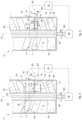
- figs. 2 and 3 show a device 10 according to the present invention for measuring the level L of fluid F inside a tank 11 for containing the fluid F, visible in its entirety in fig. 1 .
- the device 10 comprises at least one mobile level blade 12 positioned during use inside the tank 11 and at least one sensor 14, which is configured to detect at least one position of the level blade 12 and is positioned during use outside the tank 11.
- the level blade 12 is configured to interact with the sensor 14 when the level L of fluid F in the tank 11 is greater than or equal to a level L1 of fluid F to be detected, also referred to hereafter in the description as threshold level.
- the level blade 12 is configured to lower when the level L of fluid F in the tank 11 falls below the level L1 to be detected, thus varying its interaction with the sensor 14 which detects such variation and therefore the lowering of the level L of fluid below the level L1.
- the level L1 to be detected can be, for example, a minimum threshold level of fluid F inside the tank 11.
- the senor 14 can be positioned substantially at the same height as the level L1 to be detected.
- the level blade 12 can be provided with at least one magnet 13 and the sensor 14 can be a magnetic sensor.
- the magnet 13 is positioned substantially at the same height as the sensor 14 and possibly at the same height as the level L1 to be detected.
- the level blade 12 can be made entirely or in part of metal material and the sensor 14 can be an inductive sensor that detects the movement of the level blade 12.
- the senor 14 can be a capacitive sensor configured to detect the change in capacitance of the level blade 12 due to the movement of the level blade 12.
- the level blade 12 can also comprise at least one sensor 25 configured to measure its position.
- the sensor 25 can be an electric end of travel element, an inclination sensor, a torque meter or other.
- the level blade 12 can be angularly pivoting freely around a pin 15, being mounted idle on the pin 15.
- the level blade 12 comprises an upper part 16 and a lower part 17 with respect to the pin 15, both of which can be configured as fins that project from opposite parts, one with respect to the other, from the pin 15, being in fact disposed angularly offset by about 180° with respect to each other, with reference to the axis of the pin 15.
- the magnet 13 is positioned on the upper part 16 of the level blade 12.
- the lower part 17 can have a counterweight function for the level blade 12.
- the level blade 12 could be associated with an element floating in the fluid F at the level L1, therefore in such a way that the magnet 13 can interact with the sensor 14 as long as the level L of fluid F is greater than or equal to level L1.
- the level blade 12 could then lower and move to a height lower than level L1 and lower than the sensor 14 when the level L of fluid F is lower than level L1, thus interrupting the interaction between the magnet 13 and the sensor 14.
- the sensor 14 used can be for example a magnetic sensor provided with a foil electric contact which is normally open and which closes in the presence of a magnetic field, therefore when the magnet 13 is in the proximity of the sensor 14 and interacts with the latter, as in fig. 1 .
- the sensor 14 could be a Hall-effect or magneto-resistive magnetic sensor, provided with greater sensitivity.
- the level blade 12 can angularly pivoting around the pin 15 at least from a first substantially vertical position, in which the level L of fluid F is higher than the level L1, to at least a second substantially horizontal or inclined position, preferably by an angle equal to approximately 45°, in which the level L of fluid F is lower than the level L1, or vice versa.
- the pivoting pin 15 of the level blade 12 can be directed substantially in the horizontal direction.
- the level blade 12 can be made by means of durable plastic, or steel, or stainless steel, or an aluminum alloy.
- the level blade 12 could also be of a different shape from what is shown, for example rectangular or other.
- the tank 11 comprises one or more stirring blades 18 able to rotate around an axis of rotation A1 by means of corresponding drive means 19, and to stir the fluid F contained in the tank 11.
- a device 10 for measuring the level L of fluid F as described above is housed in the tank 11.
- the stirring blades 18 can be suitably disposed on one side and on the other with respect to a rotation shaft 20 directed along the axis A1 and associated with the drive means 19.
- the stirring blades 18 can be horizontal or suitably inclined, as shown by way of example in figs. 1-3 .
- the axis of rotation A1 can be substantially vertical, defining a longitudinal direction of the tank 11.
- the tank 11 can have a substantially cylindrical shape and the axis A1 can be the axis of symmetry of the tank 11.
- the tank 11 can have the shape of an "8", seen in plan view from above, that is, being formed by two cylinders interpenetrating each other, as described for example in patent documents EP 1744826 and US 10751679 of the same Applicant.
- the drive means 19, as well as the sensor 14, can be connected to a control system 21.
- the control system 21 can be part of a dispensing machine, in which one or more tanks 11 can be provided, each of which can be equipped with its own device 10 for measuring the level L of fluid F.
- the sensor 14 and the drive means 19 communicate with the control system 21 in order to receive or transmit information, according to modes known in the state of the art and not described in detail here, in order to determine the correct functioning of the machine.
- the sensor 14 communicates to the control system 21 a signal indicative of the interaction between the level blade 12 and the sensor 14, which allows the control system 21 to know whether the level blade 12 is in the first or in the second operating configuration.
- the level blade 12 of the device 10 is preferably integral with the stirring blades 18.
- the pivoting pin 15 of the level blade 12 can for example be fixed to the shaft 20.
- the level blade 12 can comprise coupling elements 22 suitable to allow its positioning on the fixed pin 15, for example two snap-in coupling elements 22 or other.
- the level blade 12 could also be equipped with its own support structure which is fixed to shaft 20.
- the pivoting pin 15 of the level blade 12 can be directed along an axis A2 substantially orthogonal to the axis of rotation A1 of the stirring blades 18.
- the level blade 12 can be positioned between at least two stirring blades 18 located in succession, in such a way as to substantially occupy, at least partly, the empty space between the two stirring blades 18.
- the upper part 16 of the level blade 12 can comprise at least one segment 23 interfering with an upper stirring blade 18.
- the lower part 17 of the level blade 12 can comprise at least one segment 24 interfering with a lower stirring blade 18.
- segment 23 or 24, or of both segments 23 and 24, as shown allows the level blade 12 to rotate in the direction R1 from the first position, shown in figs. 1 and 2 , to the second position shown in fig. 3 , or vice versa, see arrow R2, but not to go beyond the first substantially vertical position during the rotation in the direction R2.
- the segment 23 will abut with a rear surface of the upper stirring blade 18 and the segment 24 will abut with a front surface of the lower stirring blade 18, as shown by way of example in fig. 1 .
- the limitation of the rotation in direction R2 in such a way that the level blade 12 cannot go beyond the substantially vertical position of figs. 1 and 2 can also be obtained with only one of the two interference segments 23 or 24.
- the position of the pin 15 around which the level blade 12 can pivot, as well as the position of the sensor 14, can be adjustable in height, in such a way that the height of the level L1 to be detected can be substantially adjusted.
- the stirring blades 18 are rotated around the axis A1 in the direction R3 in order to stir the fluid F contained in the tank 11.
- the level blade 12 rotates together with the stirring blades 18 and contributes to the stirring of the fluid F.
- the level blade 12 When the level L of the fluid F in the tank 11 is greater than or equal to the height at which the sensor 14 is positioned, that is, the level L1 to be detected, the level blade 12 is positioned vertically and the magnet 13 is substantially at the same height as the sensor 14. In this situation, the sensor 14 detects the magnetic field generated by the magnet 13 at each pass, therefore at each revolution of the level blade 12.
- the stirring blades 18 When the stirring blades 18 are activated and the level L of the fluid F in the tank 11 is lower than the height at which the sensor 14 is positioned, that is, the level L1 to be detected, the level blade 12 inclines significantly, for example moving to approximately 45° or more, until it is disposed almost horizontally.
- the magnetic sensor When it is in this position, the magnetic sensor does not detect the magnetic field generated by the magnet 13. In fact, the magnet 13 is at a lower level than the level L1 and the level of the sensor 14, therefore the sensor 14 does not detect any signal when the level blade 12 passes.
- each tank 11 of a dispensing machine can contain a determinate type of coloring fluid, bases for paints, varnishes, enamels, inks or other.
- the stirring blades 18 when the level of the fluid in the tank falls below the level L1, it can be provided to carry out at least one rotation of the stirring blades 18 around their axis of rotation A1 in order to facilitate the movement of the level blade 12 from the first vertical position to the second position.
Landscapes
- Physics & Mathematics (AREA)
- Fluid Mechanics (AREA)
- General Physics & Mathematics (AREA)
- Chemical & Material Sciences (AREA)
- Chemical Kinetics & Catalysis (AREA)
- Measurement Of Levels Of Liquids Or Fluent Solid Materials (AREA)
Description
- The present invention concerns a tank comprising a device for measuring the level of fluid contained therein.
- The present invention also concerns a method to measure the level of fluid in a tank by means of said measuring device.
- In particular, the tank can be a tank for containing fluid products such as coloring liquids, bases for paints, varnishes, enamels, inks and suchlike, suitable to be installed on machines for dispensing or distributing such fluid products.
- In particular, the measuring device is able to detect at least one level of fluid in the tank, or at least a minimum level of fluid inside the tank.
- Machines for dispensing or distributing fluid products are known, such as dyes of different shades or colors, able to be mixed together and/or added to a base substance to make up a varnish or a paint of a determinate color.
- Known machines normally comprise a plurality of containers containing a determinate dye, which can be selectively connected to one or more delivery nozzles and associated with respective pump means which cause the selective delivery of the fluid product contained therein in a suitably selected quantity, for example with the aid of an electronic processor.
- Each container comprises inside it a stirring device, which can be selectively activated, able to prevent the heavier components present in the fluid from settling on the bottom of the container itself, with a consequent undesired drying of the fluid. The stirring device is also able to prevent the various components present in the fluid - typically characterized by different densities/viscosities - from separating, in order to prevent product degradation.
- To date, in dispensing machines generally available on the market, in particular in those installed in points of sale, there is no system for the direct measurement of the quantity of dye present in each tank.
- The level is typically recorded manually by the user when filling the tank and then the software system to manage and control the machine keeps track of it, based on the subsequent dispensing of quantities that are made. Clearly this system has obvious limits of potential misalignments between the actual value inside the tank and the "theoretical" value present in the system, mainly due to possible errors or oversights by the operator.
- A misalignment error regarding the theoretical and real quantity of dye in the tank can lead to dispensing being started, because the system believes there is enough product in the tank, when in reality there is not enough. This situation, which as of today cannot be intercepted and verifiable, creates an incorrect dispensing, which is naturally undesirable for the customer and end user, in terms of costs and the wrong quantity of product received.
- In some applications, for example industrial applications, where required, pressure sensors are used that detect the quantity of product inside the tank, since the specific weight of the product and the tare weight are known. This system has various limitations, including the high cost, the need for setting, the need to create a complex "floating" system able to be sensitive to pressure.
- Other known systems provide to use sensors "in contact" with the fluid, which however are specific for a determinate type of fluid but which adapt with difficulty to fluids of a different kind, for example different types of dye, or other fluids with different viscosity.
- The document
WO 01/42014 A2 - There are also capacitive sensors that determine the presence or absence of dye. However, these systems are complex, expensive and do not guarantee an optimal detection of at least a determinate level of fluid inside the tank, for example a minimum level of fluid that should be readily detected by the control system of the dispensing machine.
- There is therefore a need to perfect a device for measuring the level of fluid in a tank, and a tank comprising said measuring device which can overcome at least one of the disadvantages of the state of the art.
- In particular, one purpose of the present invention is to provide a device for measuring the level of fluid in a tank which is efficient, economical and can be applied in any type of tank and with any type of fluid present in the tank, in particular but not exclusively, coloring liquids, bases for paints, varnishes, enamels, inks and suchlike.
- Another purpose of the present invention is to provide a device for measuring the level of fluid in a tank in which the sensor able to detect the level of fluid, in particular when a certain level of fluid is reached, is not in direct contact with the fluid to be measured.
- Another purpose of the present invention is to provide a tank to contain a fluid product to which a device for measuring the level of fluid can be applied, irrespective of the shape and size of the tank and irrespective of the nature of the fluid contained.
- The Applicant has devised, tested and embodied the present invention to overcome the shortcomings of the state of the art and to obtain these and other purposes and advantages.
- The present invention is set forth and characterized in the independent claims. The dependent claims describe other characteristics of the present invention or variants to the main inventive idea.
- In accordance with the above purposes and according to the present invention, a tank for containing a fluid comprises both one or more stirring blades able to rotate by means of corresponding drive means in order to stir the fluid contained in the tank, and also a device for measuring the level of fluid contained in the tank.
- The device for measuring the level of fluid comprises at least one mobile level blade positioned during use inside the tank, and at least one sensor configured to detect at least one position of the level blade and positioned during use outside the tank. The level blade is configured to interact with the sensor in order to determine the level of fluid in the tank in relation to a threshold level, in correspondence with which the sensor can preferably be positioned. The level blade is configured to alternatively assume a first operating configuration when the level of fluid in the tank is greater than or equal to the threshold level, and a second operating configuration when the level of fluid in the tank falls below such threshold level; the relative position between the level blade and the sensor thus varying in the passage from the first operating configuration to the second operating configuration, which allows to detect a variation of interaction between the level blade and the sensor, which is indicative of the lowering of the level of fluid below the threshold level.
- In one particular embodiment, in the first operating configuration the level blade is disposed substantially vertically, while in the second embodiment it is disposed substantially horizontally or inclined by an angle smaller than about 60°, preferably approximately equal to 45°.
- Advantageously, the present device, equipped with a level blade which is lowered when the level of fluid in the tank falls below a threshold level and also equipped with a sensor interacting with the level blade, is efficient, economical and can be applied in any type of tank and with any type of fluid present in the tank, in particular but not exclusively coloring liquids, bases for paints, varnishes, enamels, inks and suchlike. Furthermore, the sensor is not in direct contact with the fluid contained in the tank.
- According to other aspects of the invention, the level blade can be provided with at least one magnet and the sensor can be a magnetic sensor; such magnet is positioned substantially at the same height as the sensor.
- In other embodiments, the level blade can be made, in whole or in part, of metal material and the sensor can be an inductive sensor.
- In other embodiments, the sensor can be a capacitive sensor configured to detect the capacitance variation due to the movement of the level blade.
- The level blade can also comprise at least one sensor configured to measure its position.
- According to other aspects of the invention, the level blade can be angularly pivoting around a pin, and comprise an upper part and a lower part with respect to the pin. The magnet, if provided, will in this case be positioned on the upper part of the level blade.
- In particular, the level blade can pivot around the pin at least from a first substantially vertical position, in which the level of fluid is higher than the threshold level, to at least a second substantially horizontal or inclined position, in which the level of fluid is lower than the threshold level, or vice versa.
- In particular, the level blade is configured to angularly pivot freely around the pin, since it is mounted idle on the latter.
- The level blade can be made with resistant plastic material, such as for example one or more polymers of a technical type, or steel, or stainless steel, or an aluminum alloy.
- According to the claimed invention, the level blade of the measuring device is integral with the stirring blades.
- The level blade can also be positioned between at least two stirring blades located in succession, so as to substantially occupy, at least partly, the empty space between the two stirring blades.
- The upper part of the level blade can comprise at least one segment interfering with an upper stirring blade.
- The lower part of the level blade can comprise at least one segment interfering with a lower stirring blade.
- In the present tank, the position of the pin around which the level blade angularly pivots can also be adjustable in height so as to detect a desired level of fluid.
- Another aspect of the present invention concerns a method to measure the level of fluid inside a tank for containing the fluid comprising one or more stirring blades able to rotate around an axis of rotation of their own by means of corresponding drive means in order to stir the fluid, wherein the method provides the positioning of at least one mobile level blade inside the tank and the positioning outside the tank of at least one sensor configured to detect at least one position of the level blade, wherein the level blade is configured to interact with the sensor in order to determine the level of fluid in the tank in relation to a threshold level, in correspondence with which the sensor is preferably positioned. The method according to the present invention provides that the level blade alternatively assumes, in an automatic way, that is, without any external actuation, a first operating configuration when the level of fluid in the tank is greater than or equal to the threshold level, and a second operating configuration when the level of fluid in the tank falls below such threshold level; wherein the method also provides that the relative position of the level blade varies with respect to the sensor in the passage from the first operating configuration to the second operating configuration, which allows to detect a variation of interaction between the level blade and the sensor which is indicative of the lowering of level of fluid below the threshold level.
- According to another aspect, the method according to the present invention provides that the movement of the level blade between the first and the second operating configuration is obtained by driving in rotation, by means of the drive means, the stirring blade to which the level blade is integrally fixed. In this embodiment, the rotation of the stirring blade around its own axis of rotation determines the movement of the level blade between the two configurations as above, as a function of the level of fluid as described above.
- According to another aspect, the method according to the present invention provides to carry out at least one rotation of the stirring blades in order to determine the movement of the level blade between the first operating configuration, in which the level blade is disposed in a first substantially vertical position, and the second operating configuration, in which the level blade is disposed in a second substantially horizontal or inclined position, preferably by an angle smaller than 60°, in particular approximately equal to 45°.
- These and other aspects, characteristics and advantages of the present invention will become apparent from the following description of some embodiments, given as a non-restrictive example with reference to the attached drawings wherein:
-
fig. 1 is a schematic, lateral, longitudinal section view of a tank for containing a fluid in which there is positioned a device for measuring the level of the fluid according to the present invention; -
figs. 2 and 3 are schematic, lateral, partly sectioned views of a lower part of the tank offig. 1 , which show the measuring device in two different operating conditions, as a function of the level of the fluid to be monitored; -
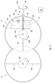
fig. 4 is a schematic top plan view of a variant of the tank offig. 1 , which also comprises a device for measuring the level of the fluid according to the present invention shown in a first operating configuration. - To facilitate comprehension, the same reference numbers have been used, where possible, to identify identical common elements in the drawings. It is understood that elements and characteristics of one embodiment can be conveniently combined or incorporated into other embodiments without further clarifications.
- We will now refer in detail to the possible embodiments of the invention, of which one or more examples are shown in the attached drawings, by way of a non-limiting illustration. The phraseology and terminology used here is also for the purposes of providing non-limiting examples.
- With reference to the attached drawings,
figs. 2 and 3 show adevice 10 according to the present invention for measuring the level L of fluid F inside atank 11 for containing the fluid F, visible in its entirety infig. 1 . - The
device 10 comprises at least onemobile level blade 12 positioned during use inside thetank 11 and at least onesensor 14, which is configured to detect at least one position of thelevel blade 12 and is positioned during use outside thetank 11. Thelevel blade 12 is configured to interact with thesensor 14 when the level L of fluid F in thetank 11 is greater than or equal to a level L1 of fluid F to be detected, also referred to hereafter in the description as threshold level. Thelevel blade 12 is configured to lower when the level L of fluid F in thetank 11 falls below the level L1 to be detected, thus varying its interaction with thesensor 14 which detects such variation and therefore the lowering of the level L of fluid below the level L1. - The level L1 to be detected can be, for example, a minimum threshold level of fluid F inside the
tank 11. - Moreover, the
sensor 14 can be positioned substantially at the same height as the level L1 to be detected. - The
level blade 12 can be provided with at least onemagnet 13 and thesensor 14 can be a magnetic sensor. Themagnet 13 is positioned substantially at the same height as thesensor 14 and possibly at the same height as the level L1 to be detected. - In other embodiments, the
level blade 12 can be made entirely or in part of metal material and thesensor 14 can be an inductive sensor that detects the movement of thelevel blade 12. - In other embodiments, the
sensor 14 can be a capacitive sensor configured to detect the change in capacitance of thelevel blade 12 due to the movement of thelevel blade 12. - The
level blade 12 can also comprise at least onesensor 25 configured to measure its position. Thesensor 25 can be an electric end of travel element, an inclination sensor, a torque meter or other. - The
level blade 12 can be angularly pivoting freely around apin 15, being mounted idle on thepin 15. Thelevel blade 12 comprises anupper part 16 and alower part 17 with respect to thepin 15, both of which can be configured as fins that project from opposite parts, one with respect to the other, from thepin 15, being in fact disposed angularly offset by about 180° with respect to each other, with reference to the axis of thepin 15. - In one embodiment, the
magnet 13 is positioned on theupper part 16 of thelevel blade 12. In this case, thelower part 17 can have a counterweight function for thelevel blade 12. - In alternative embodiments, the
level blade 12 could be associated with an element floating in the fluid F at the level L1, therefore in such a way that themagnet 13 can interact with thesensor 14 as long as the level L of fluid F is greater than or equal to level L1. Thelevel blade 12 could then lower and move to a height lower than level L1 and lower than thesensor 14 when the level L of fluid F is lower than level L1, thus interrupting the interaction between themagnet 13 and thesensor 14. - The
sensor 14 used can be for example a magnetic sensor provided with a foil electric contact which is normally open and which closes in the presence of a magnetic field, therefore when themagnet 13 is in the proximity of thesensor 14 and interacts with the latter, as infig. 1 . Alternatively, thesensor 14 could be a Hall-effect or magneto-resistive magnetic sensor, provided with greater sensitivity. - According to some embodiments, the
level blade 12 can angularly pivoting around thepin 15 at least from a first substantially vertical position, in which the level L of fluid F is higher than the level L1, to at least a second substantially horizontal or inclined position, preferably by an angle equal to approximately 45°, in which the level L of fluid F is lower than the level L1, or vice versa. The pivotingpin 15 of thelevel blade 12 can be directed substantially in the horizontal direction. - The
level blade 12 can be made by means of durable plastic, or steel, or stainless steel, or an aluminum alloy. Thelevel blade 12 could also be of a different shape from what is shown, for example rectangular or other. - The
tank 11 according to the present invention comprises one or morestirring blades 18 able to rotate around an axis of rotation A1 by means of corresponding drive means 19, and to stir the fluid F contained in thetank 11. Adevice 10 for measuring the level L of fluid F as described above is housed in thetank 11. - The stirring
blades 18 can be suitably disposed on one side and on the other with respect to arotation shaft 20 directed along the axis A1 and associated with the drive means 19. The stirringblades 18 can be horizontal or suitably inclined, as shown by way of example infigs. 1-3 . - The axis of rotation A1 can be substantially vertical, defining a longitudinal direction of the
tank 11. - With reference to the embodiment shown in
figs. 1-3 , thetank 11 can have a substantially cylindrical shape and the axis A1 can be the axis of symmetry of thetank 11. - With reference to the variant shown in
fig. 4 , thetank 11 can have the shape of an "8", seen in plan view from above, that is, being formed by two cylinders interpenetrating each other, as described for example in patent documentsEP 1744826 andUS 10751679 - The drive means 19, as well as the
sensor 14, can be connected to acontrol system 21. Thecontrol system 21 can be part of a dispensing machine, in which one ormore tanks 11 can be provided, each of which can be equipped with itsown device 10 for measuring the level L of fluid F. Thesensor 14 and the drive means 19 communicate with thecontrol system 21 in order to receive or transmit information, according to modes known in the state of the art and not described in detail here, in order to determine the correct functioning of the machine. For example, thesensor 14 communicates to the control system 21 a signal indicative of the interaction between thelevel blade 12 and thesensor 14, which allows thecontrol system 21 to know whether thelevel blade 12 is in the first or in the second operating configuration. - The
level blade 12 of thedevice 10 is preferably integral with the stirringblades 18. - The pivoting
pin 15 of thelevel blade 12 can for example be fixed to theshaft 20. Thelevel blade 12 can comprisecoupling elements 22 suitable to allow its positioning on the fixedpin 15, for example two snap-incoupling elements 22 or other. - The
level blade 12 could also be equipped with its own support structure which is fixed toshaft 20. - The pivoting
pin 15 of thelevel blade 12 can be directed along an axis A2 substantially orthogonal to the axis of rotation A1 of thestirring blades 18. - The
level blade 12 can be positioned between at least twostirring blades 18 located in succession, in such a way as to substantially occupy, at least partly, the empty space between the twostirring blades 18. - The
upper part 16 of thelevel blade 12 can comprise at least onesegment 23 interfering with anupper stirring blade 18. - The
lower part 17 of thelevel blade 12 can comprise at least onesegment 24 interfering with alower stirring blade 18. - The provision of at least one
segment segments level blade 12 to rotate in the direction R1 from the first position, shown infigs. 1 and2 , to the second position shown infig. 3 , or vice versa, see arrow R2, but not to go beyond the first substantially vertical position during the rotation in the direction R2. In particular, thesegment 23 will abut with a rear surface of theupper stirring blade 18 and thesegment 24 will abut with a front surface of thelower stirring blade 18, as shown by way of example infig. 1 . - As stated, and as can be understood, the limitation of the rotation in direction R2 in such a way that the
level blade 12 cannot go beyond the substantially vertical position offigs. 1 and2 can also be obtained with only one of the twointerference segments - The position of the
pin 15 around which thelevel blade 12 can pivot, as well as the position of thesensor 14, can be adjustable in height, in such a way that the height of the level L1 to be detected can be substantially adjusted. - The stirring
blades 18 are rotated around the axis A1 in the direction R3 in order to stir the fluid F contained in thetank 11. Thelevel blade 12 rotates together with the stirringblades 18 and contributes to the stirring of the fluid F. - When the level L of the fluid F in the
tank 11 is greater than or equal to the height at which thesensor 14 is positioned, that is, the level L1 to be detected, thelevel blade 12 is positioned vertically and themagnet 13 is substantially at the same height as thesensor 14. In this situation, thesensor 14 detects the magnetic field generated by themagnet 13 at each pass, therefore at each revolution of thelevel blade 12. - When the
stirring blades 18 are activated and the level L of the fluid F in thetank 11 is lower than the height at which thesensor 14 is positioned, that is, the level L1 to be detected, thelevel blade 12 inclines significantly, for example moving to approximately 45° or more, until it is disposed almost horizontally. When it is in this position, the magnetic sensor does not detect the magnetic field generated by themagnet 13. In fact, themagnet 13 is at a lower level than the level L1 and the level of thesensor 14, therefore thesensor 14 does not detect any signal when thelevel blade 12 passes. - As stated, the
sensor 14 can be interfaced with thecontrol system 21 of a dispensing machine which gathers the signal and supplies it to a software controlling the machine, in order to provide the status of such level L of thetank 11 or of the levels of the various tanks, if there is more than one. For example, eachtank 11 of a dispensing machine can contain a determinate type of coloring fluid, bases for paints, varnishes, enamels, inks or other. - In some versions, when the level of the fluid in the tank falls below the level L1, it can be provided to carry out at least one rotation of the
stirring blades 18 around their axis of rotation A1 in order to facilitate the movement of thelevel blade 12 from the first vertical position to the second position. - It is clear that modifications and/or additions of parts and/or steps may be made to the
device 10 for measuring the level of a fluid F in atank 11, to thetank 11 comprisingsuch device 10, and to the method to measure the level as described heretofore, without departing from the field and scope of the present invention as defined by the claims. - In the following claims, the sole purpose of the references in brackets is to facilitate reading: they must not be considered as restrictive factors with regard to the field of protection claimed in the specific claims.
Claims (14)
- Tank (11) for containing a fluid (F), comprising one or more stirring blades (18) able to rotate by means of corresponding drive means (19) in order to stir the fluid (F) contained in the tank (11), and a device (10) for measuring the level (L) of fluid (F) contained in the tank (11), characterized in that said device (10) comprises at least one mobile level blade (12) positioned, during use, inside the tank (11) integral with said stirring blades (18) and at least one sensor (14) configured to detect at least one position of said blade (12) and positioned, during use, outside the tank (11), wherein said blade (12), in order to determine the level (L) of the fluid (F) in relation to a threshold level (L1), is configured to assume a first operating configuration when the level (L) is greater than or equal to said threshold level (L1), and a second configuration when the fluid (F) falls below said threshold level (L1).
- Tank (11) as in claim 1, characterized in that said sensor (14) is a magnetic sensor and said level blade (12) is provided with at least one magnet (13) positioned substantially at the same height as said sensor (14) in at least one of said operating configurations.
- Tank (11) as in claim 1, characterized in that said level blade (12) is made entirely or partly of metal material and said sensor (14) is an inductive sensor.
- Tank (11) as in claim 1, characterized in that said sensor (14) is a capacitive sensor configured to detect the change of capacitance of the level blade (12) due to its movement.
- Tank (11) as in claim 1, characterized in that said level blade (12) comprises at least one sensor (25) configured to measure its position.
- Tank (11) as in claim 1, characterized in that said level blade (12) is angularly pivoting around a pin (15) and comprises an upper part (16) and a lower part (17) which are configured in particular as fins that project from opposite parts, one with respect to the other, with respect to said pin (15) so that the relative position of said blade (12) with respect to said sensor (14) varies in the passage from said first to said second operating configuration, which allows to detect a variation of interaction between said level blade (12) and said sensor (14) which is indicative of the lowering of the level (L) of fluid (F) below said threshold level (L1).
- Tank (11) as in claim 6, characterized in that said level blade (12) angularly pivots around said pin (15) at least between a first substantially vertical position in which said level blade (12) assumes said first operating configuration and said level (L) is higher than said threshold level (L1), to at least a second substantially horizontal or inclined position in which said level blade (12) assumes said second operating configuration where said level (L) is lower than said threshold level (L1).
- Tank (11) as in any claim 6 or 7, characterized in that said level blade (12) is configured to angularly pivot freely around said pin (15), being mounted idle on said pin (15).
- Tank as in any claim from 6 to 8, characterized in that the position of said pin (15) around which said level blade (12) angularly pivots is adjustable in height.
- Tank as in any claim hereinbefore, characterized in that said level blade (12) is positioned between at least two stirring blades (18) located in succession, so as to substantially occupy, at least partly, the empty space between said two stirring blades (18).
- Tank as in claim 10, characterized in that said upper part (16) of said level blade (12) comprises at least one segment (23) interfering with an upper stirring blade (18) and/or said lower part (17) of said level blade (12) comprises at least one segment (24) interfering with a lower stirring blade (18).
- Method to measure the level (L) of fluid contained inside a tank (11) comprising one or more stirring blades (18) able to rotate around an axis of rotation (A1) thereof by means of corresponding drive means (19) in order to stir said fluid (F), characterized in that said method provides the positioning of at least one mobile level blade (12) integral with said stirring blades (18) inside the tank (11) and of at least one sensor (14) positioned outside said tank (11) configured to detect at least one position of said level blade (12), wherein said level blade (12) is configured to interact with said sensor (14) in order to determine the level (L) of fluid (F) in relation to a threshold level (L1), and wherein said level blade (12) alternatively assumes, in an automatic and not controlled manner, a first operating configuration when the level (L) is greater than or equal to said threshold level (L1) and a second operating configuration in which the level (L) falls below said threshold level (L1).
- Method as in claim 12, characterized in that it comprises varying the relative position of said level blade (12) with respect to said sensor (14) in the passage from said first to said second operating configuration, in order to detect a variation of interaction between said level blade (12) and said sensor (14) which is indicative of the lowering of the level (L) below said threshold level (L1).
- Method as in claim 12 or 13, characterized in that it provides to carry out at least one rotation of said stirring blades (18) in order to determine the movement of said level blade (12) between said first operating configuration, in which said level blade (12) is disposed in a first substantially vertical position, and said second operating configuration, in which said level blade (12) is disposed in a second substantially horizontal or inclined position, preferably by an angle smaller than 60°, in particular approximately equal to 45°.
Applications Claiming Priority (2)
| Application Number | Priority Date | Filing Date | Title |
|---|---|---|---|
| IT102020000028676A IT202000028676A1 (en) | 2020-11-26 | 2020-11-26 | DEVICE AND METHOD OF MEASURING THE LEVEL OF FLUID IN A TANK, AND RELATIVE TANK |
| PCT/IT2021/050383 WO2022113143A1 (en) | 2020-11-26 | 2021-11-26 | Tank comprising a device for measuring the level of fluid, and corresponding measuring method |
Publications (2)
| Publication Number | Publication Date |
|---|---|
| EP4251958A1 EP4251958A1 (en) | 2023-10-04 |
| EP4251958B1 true EP4251958B1 (en) | 2025-06-11 |
Family
ID=74592528
Family Applications (1)
| Application Number | Title | Priority Date | Filing Date |
|---|---|---|---|
| EP21834948.8A Active EP4251958B1 (en) | 2020-11-26 | 2021-11-26 | Tank comprising a device for measuring the level of fluid, and corresponding measuring method |
Country Status (5)
| Country | Link |
|---|---|
| US (1) | US20240027254A1 (en) |
| EP (1) | EP4251958B1 (en) |
| CN (1) | CN116490754A (en) |
| IT (1) | IT202000028676A1 (en) |
| WO (1) | WO2022113143A1 (en) |
Families Citing this family (4)
| Publication number | Priority date | Publication date | Assignee | Title |
|---|---|---|---|---|
| IT202200023163A1 (en) * | 2022-11-10 | 2024-05-10 | Corob Spa | FLUID PRODUCT AGITATOR DEVICE |
| USD1074483S1 (en) * | 2023-02-10 | 2025-05-13 | Reign RMC, LLC | Visual indicator |
| USD1076697S1 (en) * | 2023-02-10 | 2025-05-27 | Reign RMC, LLC | Visual indicator for above-ground storage tank |
| CN117884255A (en) * | 2023-12-21 | 2024-04-16 | 山东志成磁电科技有限公司 | Iron removal device for liquid materials |
Family Cites Families (13)
| Publication number | Priority date | Publication date | Assignee | Title |
|---|---|---|---|---|
| GB1146812A (en) * | 1966-02-10 | 1969-03-26 | Thomas Cropper Ryley Shepherd | Improvements relating to material comminution apparatus |
| US5048333A (en) * | 1990-10-15 | 1991-09-17 | Phillips Petroleum Company | Material level checking apparatus for use in a rotating member |
| US5150613A (en) * | 1991-04-10 | 1992-09-29 | Etheridge Johnny E | Material level sensing device |
| US5694974A (en) * | 1996-01-24 | 1997-12-09 | Goss Graphic Systems, Inc. | Fluid level detection system for ink in a printing press |
| DE19843437C2 (en) * | 1998-09-22 | 2000-08-17 | Siemens Ag | Level measuring device |
| US6485171B1 (en) * | 1999-12-13 | 2002-11-26 | Goss Graphic Systems, Inc | Apparatus and method for sensing the fluid level in a mixing device |
| US6807814B1 (en) * | 2003-05-21 | 2004-10-26 | Hoshizaki Denki Kabushiki Kaisha | Apparatus for detecting an amount of stored ice |
| ITUD20040093A1 (en) | 2004-05-11 | 2004-08-11 | Cps Color Equipment Spa | CONTAINER TO CONTAIN FLUID PRODUCTS |
| US8032255B2 (en) * | 2008-06-30 | 2011-10-04 | Deere & Company | Monitoring of bin level for an agricultural product |
| DE102011086860B3 (en) * | 2011-11-22 | 2013-05-23 | BSH Bosch und Siemens Hausgeräte GmbH | Device for level recognition of residue collecting container in beverage brewing machine e.g. coffee machine for domestic purpose, has recognition systems that recognize position of lever pivoted between starting and release positions |
| CN107872984A (en) | 2015-01-15 | 2018-04-03 | 克洛布单股东股份公司 | Container with the agitator device for fluid product |
| CN104587874A (en) * | 2015-02-03 | 2015-05-06 | 深圳市世椿自动化设备有限公司 | Dynamic hybrid tube with alarm |
| CN108362353B (en) * | 2018-04-11 | 2024-02-27 | 成都建筑材料工业设计研究院有限公司 | Switch type wall charging position detection device |
-
2020
- 2020-11-26 IT IT102020000028676A patent/IT202000028676A1/en unknown
-
2021
- 2021-11-26 US US18/037,636 patent/US20240027254A1/en active Pending
- 2021-11-26 CN CN202180078618.8A patent/CN116490754A/en active Pending
- 2021-11-26 WO PCT/IT2021/050383 patent/WO2022113143A1/en not_active Ceased
- 2021-11-26 EP EP21834948.8A patent/EP4251958B1/en active Active
Also Published As
| Publication number | Publication date |
|---|---|
| EP4251958A1 (en) | 2023-10-04 |
| CN116490754A (en) | 2023-07-25 |
| WO2022113143A1 (en) | 2022-06-02 |
| IT202000028676A1 (en) | 2022-05-26 |
| US20240027254A1 (en) | 2024-01-25 |
Similar Documents
| Publication | Publication Date | Title |
|---|---|---|
| US20240027254A1 (en) | Tank comprising a device for measuring the level of fluid, and corresponding measuring method | |
| CA2543813C (en) | Apparatus for dispensing a plurality of fluids and container for use in the same | |
| US5568882A (en) | Precise volume fluid dispenser | |
| JP2016537109A5 (en) | Multi-serving cartridge and method for filling the multi-serving supplement cartridge with a granular dietary supplement | |
| US9550158B2 (en) | Methods of operating a metering device for the metered dispensing of pumpable media, in particular color pigment preparations, metering device and canister | |
| US4844297A (en) | Fluid dispensing apparatus and method of operation thereof | |
| US7942569B2 (en) | Metering system for preparing emulsion paints from multiple aqueous paint components | |
| EP2365911B1 (en) | Colorant fluid dispensing device for dispensing multiple colorant fluids | |
| CA1124222A (en) | Continuous outflow, weigh-measuring blender | |
| EP3767252B1 (en) | A dosing machine for dosing fluid products such as dyes for paints or the like, with a device for individually measuring the level of the fluid products | |
| EP1439000B1 (en) | Apparatus for dosing colored pigments in a container for paint or neutral enamel | |
| US8281667B2 (en) | Method for determining the mass flow through a coriolis mass flowmeter arranged on a rotating filling element | |
| US20260021493A1 (en) | Centrifuge for rotating a sample carrier | |
| CN109883882B (en) | Mud proportion detection device for highway construction | |
| EP2585883B1 (en) | Verification device to verify a container and the correct positioning of said container and relative method | |
| EP1231506B1 (en) | Photographic processor having a replenishment delivery system | |
| EP2598233B1 (en) | Apparatus for metering and delivering painting products | |
| WO2025108652A1 (en) | Liquid level measurement | |
| JPH0875532A (en) | Liquid level detector for paint tank | |
| KR200260709Y1 (en) | Liquid water automatic measurement system | |
| JPH05161837A (en) | Liquid preparing apparatus | |
| JP2007246117A (en) | Tank with inner lid | |
| KR20020006140A (en) | the horizontal distance measuring unit for reclaimer |
Legal Events
| Date | Code | Title | Description |
|---|---|---|---|
| STAA | Information on the status of an ep patent application or granted ep patent |
Free format text: STATUS: UNKNOWN |
|
| STAA | Information on the status of an ep patent application or granted ep patent |
Free format text: STATUS: THE INTERNATIONAL PUBLICATION HAS BEEN MADE |
|
| PUAI | Public reference made under article 153(3) epc to a published international application that has entered the european phase |
Free format text: ORIGINAL CODE: 0009012 |
|
| STAA | Information on the status of an ep patent application or granted ep patent |
Free format text: STATUS: REQUEST FOR EXAMINATION WAS MADE |
|
| 17P | Request for examination filed |
Effective date: 20230515 |
|
| AK | Designated contracting states |
Kind code of ref document: A1 Designated state(s): AL AT BE BG CH CY CZ DE DK EE ES FI FR GB GR HR HU IE IS IT LI LT LU LV MC MK MT NL NO PL PT RO RS SE SI SK SM TR |
|
| P01 | Opt-out of the competence of the unified patent court (upc) registered |
Effective date: 20231214 |
|
| DAV | Request for validation of the european patent (deleted) | ||
| DAX | Request for extension of the european patent (deleted) | ||
| GRAP | Despatch of communication of intention to grant a patent |
Free format text: ORIGINAL CODE: EPIDOSNIGR1 |
|
| STAA | Information on the status of an ep patent application or granted ep patent |
Free format text: STATUS: GRANT OF PATENT IS INTENDED |
|
| INTG | Intention to grant announced |
Effective date: 20250211 |
|
| GRAS | Grant fee paid |
Free format text: ORIGINAL CODE: EPIDOSNIGR3 |
|
| GRAA | (expected) grant |
Free format text: ORIGINAL CODE: 0009210 |
|
| STAA | Information on the status of an ep patent application or granted ep patent |
Free format text: STATUS: THE PATENT HAS BEEN GRANTED |
|
| AK | Designated contracting states |
Kind code of ref document: B1 Designated state(s): AL AT BE BG CH CY CZ DE DK EE ES FI FR GB GR HR HU IE IS IT LI LT LU LV MC MK MT NL NO PL PT RO RS SE SI SK SM TR |
|
| REG | Reference to a national code |
Ref country code: GB Ref legal event code: FG4D |
|
| REG | Reference to a national code |
Ref country code: CH Ref legal event code: EP |
|
| REG | Reference to a national code |
Ref country code: IE Ref legal event code: FG4D |
|
| REG | Reference to a national code |
Ref country code: DE Ref legal event code: R096 Ref document number: 602021032235 Country of ref document: DE |
|
| REG | Reference to a national code |
Ref country code: NL Ref legal event code: FP |
|
| PG25 | Lapsed in a contracting state [announced via postgrant information from national office to epo] |
Ref country code: ES Free format text: LAPSE BECAUSE OF FAILURE TO SUBMIT A TRANSLATION OF THE DESCRIPTION OR TO PAY THE FEE WITHIN THE PRESCRIBED TIME-LIMIT Effective date: 20250611 Ref country code: FI Free format text: LAPSE BECAUSE OF FAILURE TO SUBMIT A TRANSLATION OF THE DESCRIPTION OR TO PAY THE FEE WITHIN THE PRESCRIBED TIME-LIMIT Effective date: 20250611 |
|
| REG | Reference to a national code |
Ref country code: LT Ref legal event code: MG9D |
|
| PG25 | Lapsed in a contracting state [announced via postgrant information from national office to epo] |
Ref country code: NO Free format text: LAPSE BECAUSE OF FAILURE TO SUBMIT A TRANSLATION OF THE DESCRIPTION OR TO PAY THE FEE WITHIN THE PRESCRIBED TIME-LIMIT Effective date: 20250911 Ref country code: GR Free format text: LAPSE BECAUSE OF FAILURE TO SUBMIT A TRANSLATION OF THE DESCRIPTION OR TO PAY THE FEE WITHIN THE PRESCRIBED TIME-LIMIT Effective date: 20250912 |
|
| PGFP | Annual fee paid to national office [announced via postgrant information from national office to epo] |
Ref country code: IT Payment date: 20250916 Year of fee payment: 5 |
|
| PG25 | Lapsed in a contracting state [announced via postgrant information from national office to epo] |
Ref country code: BG Free format text: LAPSE BECAUSE OF FAILURE TO SUBMIT A TRANSLATION OF THE DESCRIPTION OR TO PAY THE FEE WITHIN THE PRESCRIBED TIME-LIMIT Effective date: 20250611 |
|
| PG25 | Lapsed in a contracting state [announced via postgrant information from national office to epo] |
Ref country code: HR Free format text: LAPSE BECAUSE OF FAILURE TO SUBMIT A TRANSLATION OF THE DESCRIPTION OR TO PAY THE FEE WITHIN THE PRESCRIBED TIME-LIMIT Effective date: 20250611 |
|
| PG25 | Lapsed in a contracting state [announced via postgrant information from national office to epo] |
Ref country code: RS Free format text: LAPSE BECAUSE OF FAILURE TO SUBMIT A TRANSLATION OF THE DESCRIPTION OR TO PAY THE FEE WITHIN THE PRESCRIBED TIME-LIMIT Effective date: 20250911 |
|
| PG25 | Lapsed in a contracting state [announced via postgrant information from national office to epo] |
Ref country code: LV Free format text: LAPSE BECAUSE OF FAILURE TO SUBMIT A TRANSLATION OF THE DESCRIPTION OR TO PAY THE FEE WITHIN THE PRESCRIBED TIME-LIMIT Effective date: 20250611 |
|
| PG25 | Lapsed in a contracting state [announced via postgrant information from national office to epo] |
Ref country code: PT Free format text: LAPSE BECAUSE OF FAILURE TO SUBMIT A TRANSLATION OF THE DESCRIPTION OR TO PAY THE FEE WITHIN THE PRESCRIBED TIME-LIMIT Effective date: 20251013 |
|
| PGFP | Annual fee paid to national office [announced via postgrant information from national office to epo] |
Ref country code: NL Payment date: 20251124 Year of fee payment: 5 |
|
| REG | Reference to a national code |
Ref country code: AT Ref legal event code: MK05 Ref document number: 1802597 Country of ref document: AT Kind code of ref document: T Effective date: 20250611 |
|
| PG25 | Lapsed in a contracting state [announced via postgrant information from national office to epo] |
Ref country code: IS Free format text: LAPSE BECAUSE OF FAILURE TO SUBMIT A TRANSLATION OF THE DESCRIPTION OR TO PAY THE FEE WITHIN THE PRESCRIBED TIME-LIMIT Effective date: 20251011 |
|
| PGFP | Annual fee paid to national office [announced via postgrant information from national office to epo] |
Ref country code: DE Payment date: 20251126 Year of fee payment: 5 |
|
| PG25 | Lapsed in a contracting state [announced via postgrant information from national office to epo] |
Ref country code: SM Free format text: LAPSE BECAUSE OF FAILURE TO SUBMIT A TRANSLATION OF THE DESCRIPTION OR TO PAY THE FEE WITHIN THE PRESCRIBED TIME-LIMIT Effective date: 20250611 Ref country code: AT Free format text: LAPSE BECAUSE OF FAILURE TO SUBMIT A TRANSLATION OF THE DESCRIPTION OR TO PAY THE FEE WITHIN THE PRESCRIBED TIME-LIMIT Effective date: 20250611 |
|
| PG25 | Lapsed in a contracting state [announced via postgrant information from national office to epo] |
Ref country code: CZ Free format text: LAPSE BECAUSE OF FAILURE TO SUBMIT A TRANSLATION OF THE DESCRIPTION OR TO PAY THE FEE WITHIN THE PRESCRIBED TIME-LIMIT Effective date: 20250611 |
|
| PG25 | Lapsed in a contracting state [announced via postgrant information from national office to epo] |
Ref country code: PL Free format text: LAPSE BECAUSE OF FAILURE TO SUBMIT A TRANSLATION OF THE DESCRIPTION OR TO PAY THE FEE WITHIN THE PRESCRIBED TIME-LIMIT Effective date: 20250611 |
|
| PG25 | Lapsed in a contracting state [announced via postgrant information from national office to epo] |
Ref country code: EE Free format text: LAPSE BECAUSE OF FAILURE TO SUBMIT A TRANSLATION OF THE DESCRIPTION OR TO PAY THE FEE WITHIN THE PRESCRIBED TIME-LIMIT Effective date: 20250611 |
|
| PG25 | Lapsed in a contracting state [announced via postgrant information from national office to epo] |
Ref country code: SK Free format text: LAPSE BECAUSE OF FAILURE TO SUBMIT A TRANSLATION OF THE DESCRIPTION OR TO PAY THE FEE WITHIN THE PRESCRIBED TIME-LIMIT Effective date: 20250611 |
|
| PG25 | Lapsed in a contracting state [announced via postgrant information from national office to epo] |
Ref country code: RO Free format text: LAPSE BECAUSE OF FAILURE TO SUBMIT A TRANSLATION OF THE DESCRIPTION OR TO PAY THE FEE WITHIN THE PRESCRIBED TIME-LIMIT Effective date: 20250611 |
|
| REG | Reference to a national code |
Ref country code: DE Ref legal event code: R097 Ref document number: 602021032235 Country of ref document: DE |
|
| PG25 | Lapsed in a contracting state [announced via postgrant information from national office to epo] |
Ref country code: DK Free format text: LAPSE BECAUSE OF FAILURE TO SUBMIT A TRANSLATION OF THE DESCRIPTION OR TO PAY THE FEE WITHIN THE PRESCRIBED TIME-LIMIT Effective date: 20250611 |
|
| PLBE | No opposition filed within time limit |
Free format text: ORIGINAL CODE: 0009261 |
|
| STAA | Information on the status of an ep patent application or granted ep patent |
Free format text: STATUS: NO OPPOSITION FILED WITHIN TIME LIMIT |
|
| REG | Reference to a national code |
Ref country code: CH Ref legal event code: L10 Free format text: ST27 STATUS EVENT CODE: U-0-0-L10-L00 (AS PROVIDED BY THE NATIONAL OFFICE) Effective date: 20260423 |