EP4251893B1 - Dispositif de guidage à sureté renforée - Google Patents
Dispositif de guidage à sureté renforée Download PDFInfo
- Publication number
- EP4251893B1 EP4251893B1 EP21811336.3A EP21811336A EP4251893B1 EP 4251893 B1 EP4251893 B1 EP 4251893B1 EP 21811336 A EP21811336 A EP 21811336A EP 4251893 B1 EP4251893 B1 EP 4251893B1
- Authority
- EP
- European Patent Office
- Prior art keywords
- element part
- female element
- bearing
- housing
- axis
- Prior art date
- Legal status (The legal status is an assumption and is not a legal conclusion. Google has not performed a legal analysis and makes no representation as to the accuracy of the status listed.)
- Active
Links
Images





Classifications
-
- B—PERFORMING OPERATIONS; TRANSPORTING
- B64—AIRCRAFT; AVIATION; COSMONAUTICS
- B64C—AEROPLANES; HELICOPTERS
- B64C13/00—Control systems or transmitting systems for actuating flying-control surfaces, lift-increasing flaps, air brakes, or spoilers
- B64C13/02—Initiating means
- B64C13/04—Initiating means actuated personally
- B64C13/042—Initiating means actuated personally operated by hand
- B64C13/0421—Initiating means actuated personally operated by hand control sticks for primary flight controls
-
- F—MECHANICAL ENGINEERING; LIGHTING; HEATING; WEAPONS; BLASTING
- F16—ENGINEERING ELEMENTS AND UNITS; GENERAL MEASURES FOR PRODUCING AND MAINTAINING EFFECTIVE FUNCTIONING OF MACHINES OR INSTALLATIONS; THERMAL INSULATION IN GENERAL
- F16C—SHAFTS; FLEXIBLE SHAFTS; ELEMENTS OR CRANKSHAFT MECHANISMS; ROTARY BODIES OTHER THAN GEARING ELEMENTS; BEARINGS
- F16C35/00—Rigid support of bearing units; Housings, e.g. caps, covers
- F16C35/02—Rigid support of bearing units; Housings, e.g. caps, covers in the case of sliding-contact bearings
-
- F—MECHANICAL ENGINEERING; LIGHTING; HEATING; WEAPONS; BLASTING
- F16—ENGINEERING ELEMENTS AND UNITS; GENERAL MEASURES FOR PRODUCING AND MAINTAINING EFFECTIVE FUNCTIONING OF MACHINES OR INSTALLATIONS; THERMAL INSULATION IN GENERAL
- F16C—SHAFTS; FLEXIBLE SHAFTS; ELEMENTS OR CRANKSHAFT MECHANISMS; ROTARY BODIES OTHER THAN GEARING ELEMENTS; BEARINGS
- F16C35/00—Rigid support of bearing units; Housings, e.g. caps, covers
- F16C35/04—Rigid support of bearing units; Housings, e.g. caps, covers in the case of ball or roller bearings
- F16C35/042—Housings for rolling element bearings for rotary movement
-
- F—MECHANICAL ENGINEERING; LIGHTING; HEATING; WEAPONS; BLASTING
- F16—ENGINEERING ELEMENTS AND UNITS; GENERAL MEASURES FOR PRODUCING AND MAINTAINING EFFECTIVE FUNCTIONING OF MACHINES OR INSTALLATIONS; THERMAL INSULATION IN GENERAL
- F16C—SHAFTS; FLEXIBLE SHAFTS; ELEMENTS OR CRANKSHAFT MECHANISMS; ROTARY BODIES OTHER THAN GEARING ELEMENTS; BEARINGS
- F16C35/00—Rigid support of bearing units; Housings, e.g. caps, covers
- F16C35/04—Rigid support of bearing units; Housings, e.g. caps, covers in the case of ball or roller bearings
- F16C35/06—Mounting or dismounting of ball or roller bearings; Fixing them onto shaft or in housing
- F16C35/067—Fixing them in a housing
-
- G—PHYSICS
- G05—CONTROLLING; REGULATING
- G05G—CONTROL DEVICES OR SYSTEMS INSOFAR AS CHARACTERISED BY MECHANICAL FEATURES ONLY
- G05G9/00—Manually-actuated control mechanisms provided with one single controlling member co-operating with two or more controlled members, e.g. selectively, simultaneously
- G05G9/02—Manually-actuated control mechanisms provided with one single controlling member co-operating with two or more controlled members, e.g. selectively, simultaneously the controlling member being movable in different independent ways, movement in each individual way actuating one controlled member only
- G05G9/04—Manually-actuated control mechanisms provided with one single controlling member co-operating with two or more controlled members, e.g. selectively, simultaneously the controlling member being movable in different independent ways, movement in each individual way actuating one controlled member only in which movement in two or more ways can occur simultaneously
- G05G9/047—Manually-actuated control mechanisms provided with one single controlling member co-operating with two or more controlled members, e.g. selectively, simultaneously the controlling member being movable in different independent ways, movement in each individual way actuating one controlled member only in which movement in two or more ways can occur simultaneously the controlling member being movable by hand about orthogonal axes, e.g. joysticks
-
- F—MECHANICAL ENGINEERING; LIGHTING; HEATING; WEAPONS; BLASTING
- F16—ENGINEERING ELEMENTS AND UNITS; GENERAL MEASURES FOR PRODUCING AND MAINTAINING EFFECTIVE FUNCTIONING OF MACHINES OR INSTALLATIONS; THERMAL INSULATION IN GENERAL
- F16C—SHAFTS; FLEXIBLE SHAFTS; ELEMENTS OR CRANKSHAFT MECHANISMS; ROTARY BODIES OTHER THAN GEARING ELEMENTS; BEARINGS
- F16C2326/00—Articles relating to transporting
- F16C2326/43—Aeroplanes; Helicopters
-
- G—PHYSICS
- G05—CONTROLLING; REGULATING
- G05G—CONTROL DEVICES OR SYSTEMS INSOFAR AS CHARACTERISED BY MECHANICAL FEATURES ONLY
- G05G9/00—Manually-actuated control mechanisms provided with one single controlling member co-operating with two or more controlled members, e.g. selectively, simultaneously
- G05G9/02—Manually-actuated control mechanisms provided with one single controlling member co-operating with two or more controlled members, e.g. selectively, simultaneously the controlling member being movable in different independent ways, movement in each individual way actuating one controlled member only
- G05G9/04—Manually-actuated control mechanisms provided with one single controlling member co-operating with two or more controlled members, e.g. selectively, simultaneously the controlling member being movable in different independent ways, movement in each individual way actuating one controlled member only in which movement in two or more ways can occur simultaneously
- G05G9/047—Manually-actuated control mechanisms provided with one single controlling member co-operating with two or more controlled members, e.g. selectively, simultaneously the controlling member being movable in different independent ways, movement in each individual way actuating one controlled member only in which movement in two or more ways can occur simultaneously the controlling member being movable by hand about orthogonal axes, e.g. joysticks
- G05G2009/04703—Mounting of controlling member
- G05G2009/04714—Mounting of controlling member with orthogonal axes
- G05G2009/04718—Mounting of controlling member with orthogonal axes with cardan or gimbal type joint
-
- G—PHYSICS
- G05—CONTROLLING; REGULATING
- G05G—CONTROL DEVICES OR SYSTEMS INSOFAR AS CHARACTERISED BY MECHANICAL FEATURES ONLY
- G05G9/00—Manually-actuated control mechanisms provided with one single controlling member co-operating with two or more controlled members, e.g. selectively, simultaneously
- G05G9/02—Manually-actuated control mechanisms provided with one single controlling member co-operating with two or more controlled members, e.g. selectively, simultaneously the controlling member being movable in different independent ways, movement in each individual way actuating one controlled member only
- G05G9/04—Manually-actuated control mechanisms provided with one single controlling member co-operating with two or more controlled members, e.g. selectively, simultaneously the controlling member being movable in different independent ways, movement in each individual way actuating one controlled member only in which movement in two or more ways can occur simultaneously
- G05G9/047—Manually-actuated control mechanisms provided with one single controlling member co-operating with two or more controlled members, e.g. selectively, simultaneously the controlling member being movable in different independent ways, movement in each individual way actuating one controlled member only in which movement in two or more ways can occur simultaneously the controlling member being movable by hand about orthogonal axes, e.g. joysticks
- G05G2009/04766—Manually-actuated control mechanisms provided with one single controlling member co-operating with two or more controlled members, e.g. selectively, simultaneously the controlling member being movable in different independent ways, movement in each individual way actuating one controlled member only in which movement in two or more ways can occur simultaneously the controlling member being movable by hand about orthogonal axes, e.g. joysticks providing feel, e.g. indexing means, means to create counterforce
-
- G—PHYSICS
- G05—CONTROLLING; REGULATING
- G05G—CONTROL DEVICES OR SYSTEMS INSOFAR AS CHARACTERISED BY MECHANICAL FEATURES ONLY
- G05G2505/00—Means for preventing, limiting or returning the movements of parts of a control mechanism, e.g. locking controlling member
Definitions
- the present invention relates to the field of rotating connection devices.
- a flight control device for an aircraft comprising a frame on which a frame is rotatably mounted about a first axis.
- a control arm for connection to a control handle is rotatably mounted on the frame and comprises a pitch cross member rotatably mounted on the control arm.
- a roll cross member rotatably mounted on the frame is connected to a roll shaft rotatably mounted on the roll cross member.
- the roll shaft is connected to a roll motor.
- a pitch motor comprises a pitch shaft rotatably mounted on the pitch cross member.
- the pitch and roll motors provide haptic feedback to the user of the flight control device and a measurement of the commands (roll and pitch) applied by the user to the control handle.
- Such a control device implements six rotational connection devices.
- the rotational connection is provided by a shaft of a male element mounted for rotation relative to a housing of a female element using a bearing received in a housing of the female element.
- the bearing may escape from its housing or become stuck there and thus cause the total or partial loss of the control function. Since this loss could lead to a catastrophic situation, there is a need to protect the rotating connections of such a control device. against breakage of the male and female elements.
- the invention aims in particular to preserve a rotational guidance function between a male element and a female element in the event of one of the elements breaking.
- the invention aims to ensure that the haptic feedback and displacement measurement functions of a control handle connected to the flight control device are retained despite the breakage of one of the elements of the flight control device.
- a rotational connection device comprising a female element and a male element mounted in the female element for rotation about a first axis via a rotational guide bearing.
- each element comprises two parts arranged to both support the bearing so as to maintain the bearing in position independently of a breakage of one of the parts of the same element.
- a bearing is carried by a part when the part ensures fixed positioning of the bearing relative to said part and it takes up the components, normal to the axis of rotation of the bearing, of the forces applied to the bearing.
- the female element comprises a first female element part and a second female element part
- the bearing comprises first means for fixing to the first female element part and second means for fixing to the second female element part.
- first fixing means and/or the second fixing means comprise an ear projecting from an external surface of the guide bearing.
- connection of the bearing to the elements is facilitated when the ear includes at least one drilling.
- the female element comprises a first housing for receiving the bearing, defined jointly by the first female element part and by the second female element part, the first female element part defining a first sector of the first housing centered around the first axis and the second female element part defining a second sector of the first housing centered around the first axis. It is possible to produce symmetrical elements when the first sector has a first amplitude substantially equal to one hundred and eighty degrees and the second sector has a second amplitude substantially equal to one hundred and eighty degrees.
- the female element comprises a first housing for receiving the bearing, jointly defined by a first female element part defining a first portion of the first housing and by a second female element part defining a second portion of the first housing, the first portion of the first housing and the second portion of the first housing extending on either side of a first plane orthogonal to the first axis.
- the second female element part includes a first half-shell and a second half-shell assembled together.
- the female element comprises a first female element part defining a first housing for receiving the bearing and a second female element part defining a second housing for receiving the first female element part.
- the male element comprises a first male element part and a second male element part provided with third means for their rotational connection around the first axis.
- the device is very compact when the first male element part comprises a first lumen through which the second male element part extends at least partially.
- the transmission of forces is particularly effective when the first lumen extends in a direction substantially parallel to the first axis and/or the first male element part also comprises a second lumen which extends in a direction substantially orthogonal to the first axis and through which the second male element part extends at least partially.
- the male element comprises a first male element part fitted into a second male element part.
- the male element comprises a second connecting device rotating around a second axis.
- a second connecting device rotating around a second axis finds a particularly interesting application when the second connecting device rotating around a second axis conforms to one of the devices described above.
- the invention also relates to a flight control device for an aircraft, comprising a frame, a frame mounted for rotation relative to the frame about a first main axis and a control arm for connection to a manual handling interface and rotatably mounted on the frame using a first rotational connection device.
- a roll cross member is rotatably mounted on the frame using a second rotational connection device.
- a pitch cross member is rotatably mounted on the control arm using a third rotational connection device.
- a roll motor is fixedly mounted relative to the frame and includes a roll shaft rotatably mounted on the roll cross member using a fourth rotational connection device.
- a pitch motor is fixedly mounted relative to the frame and includes a pitch shaft rotatably mounted on the pitch cross member using a fifth rotational connection device.
- the first to fifth rotational guide devices are in accordance with one of those described above.
- the frame 20 is of substantially parallelepiped shape and comprises two small faces 21 and 22 which respectively carry a first bearing 23 - here a ball bearing - and a second bearing 24 - here a ball bearing - for the articulation of the frame 20 around the first axis O1.
- the first large face 25 comprises a third bearing 26 and a fourth bearing 27.
- the second large face 28 comprises a fifth bearing 29 and a sixth bearing 30.
- the frame 20 comprises a first part 20.1 and a second part 20.2, here a first half-frame 20.1 and a second half-frame 20.2, assembled along a joint plane containing the axes O2 and O3 and connected to each other by bolting.
- the third bearing 26 is received in a first cylindrical housing 31 of the frame 20.
- the first housing 31 is jointly defined by the first half-frame 20.1 and by the second half-frame 20.2.
- the first half-frame 20.1 defines a first sector 31.1 of the first housing 31 centered around the second axis O2 and the second half-frame 20.2 defines a second sector 31.2 of the first housing 31 centered around the first axis.
- the first sector 31.1 and the second sector 31.2 both have, here, an amplitude of one hundred and eighty degrees and are open on the joint plane.
- the third bearing 26 comprises an outer ring provided with a first ear 32 and a second ear 33 projecting from the outer ring 26.1.
- the first ear 32 and the second ear 33 are diametrically opposed and respectively received in notches made in the frame 20 straddling the first half-frame 20.1 and the second half-frame 20.2 to open into the first housing 31.
- the first ear 32 comprises a first bore 32.1 and a second bore 32.2 which respectively accommodate a first fixing screw to the first half-frame 20.1 and a second fixing screw to the second half-frame 20.2 (not shown).
- the second ear 33 comprises a third bore 33.1 and a fourth bore 33.2 which respectively accommodate a third fixing screw to the first half-frame 20.1 and a fourth fixing screw to the second half-frame 20.2 (not shown).
- the third bearing 26 is carried by the first half-frame 20.1 via the first and third screws, and by the second half-frame 20.2 via the second and fourth screws.
- the third bearing 26 is carried by the second half-frame 20.2 and the function of guiding in rotation about the second axis O2 by the third bearing 26 is preserved.
- the first bearing 23, the second bearing 24, the fourth bearing 27, the fifth bearing 29 and the sixth bearing 30 are connected to the frame 20 according to arrangements similar to those described for the third bearing 26.
- the frame 20 comprises two parts, the first half-frame 20.1 and the second half-frame 20.2, which are arranged to both carry the bearings 23, 24, 26, 27, 29 and 30 so as to hold these bearings in position independently of the breakage of one of the half-frames 20.1 or 20.2.
- control arm 40 comprises a plate 40.1 for receiving a control handle 42.
- the plate 40.1 comprises means for the mechanical and electronic connection (here a connector 43) of the handle 42 to the control arm 40.
- the control arm 40 has a male element, here a first shaft 44, which is received in the third bearing 26.
- the first shaft 44 comprises two male element pieces, namely a first male element piece 45 and a second male element piece 46.
- control arm 40 comprises a first half-shell 47.1 and a second half-shell 47.2 which jointly define a second substantially cubic internal housing 48 for receiving a first core 49.
- the first half-shell 47.1 and the second half-shell 47.2 are connected to each other by means of screws 50 which also pass through the first core 49.
- Two shear pins 51 also provide a connection between the first half-shell 47.1, the second half-shell 47.2 and the first core 49.
- the first core 49 is integral in rotation about the second axis O2 of the first half-shell 47.1 and the second half-shell 47.2.
- the first male element part 45 is defined by the first half-shell 47.1 and comprises a first lumen 52 substantially coaxial with the second axis O2 and through which extends the second male element part 46 which is defined by a first protrusion 53 of the first core 49.
- the first male element part 45 also comprises a second lumen 54 which extends in a direction substantially orthogonal to the second axis O2.
- the first protrusion 53 also extends through the second lumen 54.
- the control arm 40 has another male element, here a second shaft 55, which is received in the fifth bearing 29.
- the second shaft 55 comprises, in a manner homologous to the first shaft 44, two male element parts, namely a third male element part 56 and a fourth male element part 57 respectively defined by the second half-shell 47.2 and a second protrusion 58 of the first core 49.
- control arm 40 comprises two parts, the half-shell 47.1 and the first core 49, which are arranged to both carry the third bearing 26 so as to hold the third bearing 26 in position regardless of the breakage of the first half-shell 47.1 or the first core 49.
- the first shaft 44, the second shaft 55, the third bearing 26 and the fifth bearing 29 define the second rotational connection device 41. More specifically, the first shaft 44 and the second shaft 55 of the control arm 40 define a male element of the second rotational connection device 41.
- the first housing 31 of the third bearing 26 and the housing of the fifth bearing 29 of the frame 20 define a female element of the second rotational connection device 41.
- control arm 40 comprises a third housing 60 for receiving a seventh bearing 61 - here a ball bearing - to guide a rotation around the fourth axis O4.
- the third housing 60 is jointly defined by a first portion 62 of third housing 60 and a second portion 63 of third housing 60.
- the first portion 62 of third housing 60 and the second portion 63 of the third housing 60 extend on either side of a first plane P4 orthogonal to the fourth axis O4.
- the first portion 62 corresponds to a first countersink 64 made in the first core 49 and which comprises a radial cutout 65.
- the second portion 63 corresponds to a second countersink 66 composed of a first half-countersink 66.1 made in the first half-shell 47.1 and a second half-countersink 66.2 made in the second half-shell 47.2.
- control arm 40 comprises two parts, the half-shells 47.1 and 47.2 on the one hand and the first core 49 on the other hand, which are arranged to both carry the seventh bearing 61 so as to hold the seventh bearing 61 in position independently of the breakage of the half-shells 47.1 and 47.2 or of the first core 49.
- the control arm 40 also includes a fourth housing 67 for receiving an eighth bearing 68 - here a ball bearing - to guide a rotation about the fourth axis O4.
- the fourth housing 67 is symmetrical to the third housing 60 and designed in the same way.
- the pitch cross member 100 comprises a male element, here a third shaft 102, which is received in the seventh bearing 61 and extends along the fourth axis O4.
- the third shaft 102 comprises two male element pieces, namely a fifth male element piece 103 and a sixth male element piece 104.
- the pitching crosspiece 100 comprises a third half-shell 105.1 and a fourth half-shell 105.2 which jointly define a fifth substantially cubic internal housing 106 for receiving a second core. 107.
- the third half-shell 105.1 and the fourth half-shell 105.2 are connected to each other by means of screws 108 engaged in flanges 109 secured to the half-shells 105.1 and 105.2.
- the second core 107 is rotationally secured about the fourth axis O4 to the third half-shell 105.1 and the fourth half-shell 105.2.
- the fifth male element part 103 is defined by the third half-shell 105.1 and comprises a third lumen 110 substantially coaxial with the fourth axis O4 and in which extends the sixth male element part 104 which is defined by a third protrusion 111 of the second core 107.
- the pitching cross member 100 has another male element, here a fourth shaft 112, which is received in the eighth bearing 68.
- the fourth shaft 112 comprises, in a manner homologous to the third shaft 102, a seventh male element part 113 and an eighth male element part 114 respectively defined by the fourth half-shell 105.2 and a fourth protrusion 115 of the second core 107 in a manner similar to the fifth male element part 103 and the sixth male element part 104.
- the pitching cross member 100 comprises two parts, a third half-shell 105.1 and a second core 107, which are arranged to both support the seventh bearing 61 so as to hold the seventh bearing 61 in position independently of the breakage of the third half-shell 105.1 or the second core 107.
- the third shaft 102, the fourth shaft 112, the seventh bearing 61 and the eighth bearing 68 define the fourth rotating connecting device 101.
- the third shaft 102 and the fourth shaft 112 of the pitch cross member 100 define a male element of the fourth rotational connection device 101.
- the third housing 60 and the fourth housing 67 of the control arm 40 define a female element of the fourth rotational connection device 101.
- the parts (half-shells 45.1 and 45.2 and the first core 49) constituting the male element of the second rotational connection device 41 connecting the control arm 40 to the frame 20 also comprise a female element of the fourth rotational connection device 101 connecting the control arm 40 to the pitch crosspiece 100.
- the pitching crosspiece 100 comprises a fifth housing 116 for receiving a ninth bearing 117 for guiding a rotation about the sixth axis O6.
- the ninth bearing 117 comprises a first half-bearing 117.1 and a second half-bearing 117.2 which are formed here by two roller bearings, both identical, separated by a spacer 117.3.
- the fifth housing 116 extends into the second core 107.
- the third half-shell 105.1 and the fourth half-shell 105.2 each comprise two semicircular openings which define a first circular opening 118 and a second circular opening 119.
- the inner diameter of the first opening 118 is greater than or equal to the inner diameter of the bearing 117 and less than the outer diameter of the bearing 117.
- the third half-shell 105.1 and the fourth half-shell 105.2 prevent a translation of the ninth bearing. 117 in a direction parallel to the sixth axis O6.
- the pitching crosspiece 100 therefore comprises two parts - the two half-shells 105.1 and 105.2 on the one hand and the second core 107 on the other hand - which are arranged to both carry the ninth bearing 117 so as to hold the ninth bearing 117 in position independently of the breakage of the half-shells 105.1 and 105.2 or of the second core 107.
- the pitch shaft 141 comprises two male element pieces, namely a ninth male element piece 143 and a tenth male element piece 144.
- the ninth male element part 143 comprises a cylindrical portion 145 inside which a bore 146 extends in a direction substantially parallel to the sixth axis O6.
- the ninth male element piece 143 also comprises a first base 147 provided with a first tab 148 and a second tab 149.
- the tenth male element piece 144 comprises a cylindrical portion 150 which is engaged in the bore 146.
- the tenth male element piece 144 also comprises a second base 151 provided with a first groove 152 which receives the first tab 148 and a second groove 153 which receives the second tab 149.
- the ninth male element piece 143 and the tenth male element piece 144 are connected to each other by a screw 154 and a shear pin 155.
- the pitch shaft 141 is engaged in the ninth bearing 117 of the pitch cross member 100.
- the pitch shaft 141 comprises two parts, the ninth male element part 143 and the tenth part of male element 144, which are arranged to both carry the ninth bearing 117 so as to maintain the ninth bearing 117 in position regardless of the breakage of the ninth male element piece 143 or the tenth male element piece 144.
- the ninth bearing 117 acts as a hoop around the pitch shaft 141 and thus helps to ensure the connection between the ninth male element piece 143 and the tenth male element piece 144.
- the pitch shaft 141 and the ninth bearing 117 define the sixth rotational connection device 142.
- the pitch shaft 141 defines a male element of the sixth rotational connecting device 142.
- the fifth housing 116 of the pitch cross member 100 defines a female element of the sixth rotational connecting device 142.
- the roll cross member 80 is identical to the pitch cross member 100 and the roll shaft 121 is identical to the pitch shaft 141.
- the third rotational connection device 81 which connects the frame 20 to the roll crosspiece 80 comprises a fourth bearing 27 which is carried by the first half-frame 20.1 and by the second half-frame 20.2.
- the third rotational connection device 81 also comprises two male element parts, namely an eleventh male element part 83 and a twelfth male element part 84, respectively identical to the fifth male element part 103 and to the sixth male element part 104, and which constitute a fifth shaft 82.
- the third rotational connection device 81 comprises two other male element pieces, namely a thirteenth male element piece 93 and a fourteenth male element piece 94 respectively identical to the seventh male element piece 113 and the eighth male element piece 114 and which constitute a sixth shaft 92.
- the fifth rotational connection device 122 which connects the roll cross member 80 to the roll shaft 121 comprises a tenth bearing 97 which is carried by the third core 87 of the roll cross member 80 and in which the roll shaft 121 is engaged.
- the fifth rotational connection device 122 also comprises two male element pieces, namely a fifteenth male element piece 123 and a sixteenth male element piece 130 respectively identical to the ninth male element piece 143 and the tenth male element piece 144.
- a male element - here a seventh shaft 12 - cooperates with the second bearing 24.
- another male element - here an eighth shaft 13 - cooperates with the first bearing 23.
- the seventh shaft 12 comprises a seventeenth male element part 14 of revolution which comprises a third axial slot 14.1 extending along the first axis O1.
- a third axial groove 14.2 opens into the third slot 14.1.
- An eighteenth male element part 15 extends into the third slot 14.1 and comprises a fourth axial groove 15.1 for receiving a first key 16.
- the eighth shaft 13 comprises, in a homologous manner, a nineteenth male element part 17 which accommodates a twentieth male element piece 18 connected by a second key 19.
- the seventh shaft 12 and the eighth shaft 13 define a male element of the first rotating connection device 11.
- the receiving housing of the first bearing 23 and the receiving housing of the second bearing 24 of the frame 20 define a female element of the first rotating connection device 11.
Landscapes
- Engineering & Computer Science (AREA)
- General Engineering & Computer Science (AREA)
- Mechanical Engineering (AREA)
- Automation & Control Theory (AREA)
- Physics & Mathematics (AREA)
- General Physics & Mathematics (AREA)
- Aviation & Aerospace Engineering (AREA)
- Pivots And Pivotal Connections (AREA)
- Motor Power Transmission Devices (AREA)
- Moulding By Coating Moulds (AREA)
Description
- La présente invention concerne le domaine des dispositifs de liaison en rotation.
- Il est connu de la demande de brevet
FR-A-3011815 - En cas de rupture (apparition de fissure/crique ou fracture) de l'élément mâle et/ou de l'élément femelle, le roulement peut s'échapper de son logement ou s'y coincer et ainsi provoquer la perte totale ou partielle de la fonction de commande. Cette perte pouvant aboutir à une situation catastrophique, il existe un besoin de prémunir les liaisons en rotation d'un tel dispositif de commande contre les ruptures des éléments mâle et femelle.
- L'invention a notamment pour but de préserver une fonction de guidage en rotation entre un élément mâle et un élément femelle dans le cas d'une rupture de l'un des éléments.
- Dans une application à un dispositif de commande de vol, l'invention a pour but de garantir que les fonctions de retour haptique et de mesure de déplacement d'une poignée de contrôle reliée au dispositif de commande de vol soit conservées malgré la rupture d'un des éléments du dispositif de commande de vol.
- A cet effet, on prévoit, un dispositif de liaison en rotation comprenant un élément femelle et un élément mâle monté dans l'élément femelle à rotation autour d'un premier axe via un palier de guidage en rotation. Selon l'invention, chaque élément comprend deux pièces agencées pour porter toutes deux le palier de manière à maintenir le palier en position indépendamment d'une rupture de l'une des pièces du même élément.
- Ainsi, une rupture de l'un des éléments ne provoque pas la perte du guidage en rotation.
- Au sens de la présente demande, un palier est porté par une pièce lorsque la pièce assure un positionnement fixe du palier par rapport à ladite pièce et qu'elle reprend les composantes, normales à l'axe de rotation du palier, des efforts appliqués au palier.
- Avantageusement, l'élément femelle comprend une première pièce d'élément femelle et une deuxième pièce d'élément femelle, et le palier comprend des premiers moyens de fixation à la première pièce d'élément femelle et des deuxièmes moyens de fixation à la deuxième pièce d'élément femelle.
- On obtient une réalisation particulièrement économique lorsque les premiers moyens de fixation et/ou les deuxièmes moyens de fixation comprennent une oreille venant en saillie d'une surface externe du palier de guidage.
- La liaison du palier aux éléments est facilitée lorsque l'oreille comprend au moins un perçage.
- Selon un premier mode de réalisation particulier de l'élément femelle, l'élément femelle comprend un premier logement d'accueil du palier, défini conjointement par la première pièce d'élément femelle et par la deuxième pièce d'élément femelle, la première pièce d'élément femelle définissant un premier secteur du premier logement centré autour du premier axe et la deuxième pièce d'élément femelle définissant un deuxième secteur du premier logement centré autour du premier axe. Il est possible de réaliser des éléments symétriques lorsque le premier secteur a une première amplitude sensiblement égale à cent quatre-vingt degrés et le deuxième secteur a une deuxième amplitude sensiblement égale à cent quatre-vingt degrés.
- Selon un deuxième mode de réalisation particulier de l'élément femelle, l'élément femelle comprend un premier logement d'accueil du palier, défini conjointement par une première pièce d'élément femelle définissant une première portion de premier logement et par une deuxième pièce d'élément femelle définissant une deuxième portion de premier logement, la première portion de premier logement et la deuxième portion de premier logement s'étendant de part et d'autre d'un premier plan orthogonal au premier axe.
- Il est possible de simplifier la fabrication et le montage lorsque la deuxième pièce d'élément femelle comprend une première demi-coquille et une deuxième demi-coquille assemblées l'une à l'autre.
- Selon un troisième mode de réalisation particulier de l'élément femelle, l'élément femelle comprend une première pièce d'élément femelle définissant un premier logement d'accueil du palier et une deuxième pièce d'élément femelle définissant un deuxième logement d'accueil de la première pièce d'élément femelle.
- Selon un premier mode de réalisation particulier de l'élément mâle, l'élément mâle comprend une première pièce d'élément mâle et une deuxième pièce d'élément mâle pourvues des troisièmes moyens de leur liaison en rotation autour du premier axe.
- Le dispositif est très compact lorsque la première pièce d'élément mâle comprend une première lumière au travers de laquelle s'étend au moins partiellement la deuxième pièce d'élément mâle
- La transmission des efforts est particulièrement efficace lorsque la première lumière s'étend selon une direction sensiblement parallèle au premier axe et/ou la première pièce d'élément mâle comprend également une deuxième lumière qui s'étend selon une direction sensiblement orthogonale au premier axe et au travers de laquelle s'étend au moins partiellement la deuxième pièce d'élément mâle.
- Selon un deuxième mode de réalisation particulier de l'élément mâle, l'élément mâle comprend une première pièce d'élément mâle emboîtée dans une deuxième pièce d'élément mâle.
- Avantageusement, l'élément mâle comprend un deuxième dispositif de liaison en rotation autour d'un deuxième axe. Un tel dispositif trouve une application particulièrement intéressante lorsque le deuxième dispositif de liaison en rotation autour d'un deuxième axe est conforme à l'un des dispositifs décrits ci-dessus.
- L'invention concerne également un dispositif de commande de vol d'un aéronef, comprenant un bâti, un cadre monté à rotation relativement au bâti autour d'un premier axe principal
et un bras de commande destiné à être relié à une interface de manipulation manuelle et monté à rotation sur le cadre à l'aide d'un premier dispositif de liaison en rotation. Un croisillon de roulis est monté à rotation sur le cadre à l'aide d'un deuxième dispositif de liaison en rotation. Un croisillon de tangage est monté à rotation sur le bras de commande à l'aide d'un troisième dispositif de liaison en rotation. Un moteur de roulis est monté fixe par rapport au cadre et comprend un arbre de roulis monté à rotation sur le croisillon de roulis à l'aide d'un quatrième dispositif de liaison en rotation. Un moteur de tangage est monté fixe par rapport au cadre et comprend un arbre de tangage monté à rotation sur le croisillon de tangage à l'aide d'un cinquième dispositif de liaison en rotation. Selon l'invention, les premier à cinquième dispositifs de guidage en rotation sont conformes à l'un de ceux décrits précédemment. - D'autres caractéristiques et avantages de l'invention ressortiront à la lecture de la description qui suit d'un mode de réalisation particulier de l'invention.
- Il sera fait référence aux dessins annexés, parmi lesquels :
- [
Fig. 1 ]lafigure 1 est une vue schématique en perspective d'un dispositif de commande selon l'invention, dont le bâti est représenté transparent ; - [
Fig. 2 ] lafigure 2 est une vue schématique en perspective d'un cadre du dispositif selon l'invention ; - [
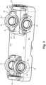
Fig. 3 ] lafigure 3 est une vue schématique partielle en perspective de lafigure 2 selon un autre angle de vue ; [Fig. 4 ] lafigure 4 est une vue schématique en perspective d'un bras de commande du dispositif selon l'invention ; [Fig. 5 ] lafigure 5 est une vue schématique éclatée en perspective du bras de commande de lafigure 4 ; - [
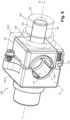
Fig. 6 ] lafigure 6 est une vue schématique en perspective d'un croisillon de tangage du dispositif selon l'invention ; - [
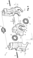
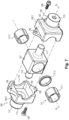
Fig. 7 ] lafigure 7 est une vue schématique éclatée en perspective du croisillon de tangage de lafigure 6 ; [Fig. 8 ] lafigure 8 est une vue schématique en perspective d'un arbre de tangage du dispositif selon l'invention ; [Fig. 9 ] lafigure 9 est une vue schématique éclatée en perspective de l'arbre de tangage de lafigure 8 ; - [
Fig. 10 ] lafigure 10 est une vue schématique éclatée en perspective d'un croisillon de roulis du dispositif selon l'invention ; - [
Fig. 11 ] lafigure 11 est une vue schématique éclatée en perspective d'un arbre de roulis du dispositif selon l'invention ; - [
Fig. 12 ] lafigure 12 est une vue schématique en coupe d'un arbre d'articulation du cadre sur le bâti ; - [
Fig. 13 ] lafigure 13 est une vue schématique en coupe d'un autre arbre d'articulation du cadre sur le bâti. - En référence à la
figure 1 , le dispositif de commande de vol selon l'invention, et généralement désigné 1 comprend : - un bâti 10,
- un cadre 20 monté à rotation relativement au bâti 10 autour d'un premier axe O1 à l'aide d'un premier dispositif de liaison en rotation 11 ;
- un bras de commande 40 monté à rotation sur le cadre 20 autour d'un deuxième axe de rotation 02 à l'aide d'un deuxième dispositif de liaison en rotation 41 ;
- un croisillon de roulis 80 monté à rotation autour d'un troisième axe de rotation 03 sur le cadre 20 à l'aide d'un troisième dispositif de liaison en rotation 81 ;
- un croisillon de tangage 100 monté à rotation autour d'un quatrième axe de rotation O4 sur le bras de commande 40 à l'aide d'un quatrième dispositif de liaison en rotation 101;
- un moteur de roulis 120 solidaire du bâti 10 et qui comprend un arbre de roulis 121 monté à rotation autour d'un cinquième axe de rotation O5 sur le croisillon de roulis 80 à l'aide d'un cinquième dispositif de liaison en rotation 122.
- un moteur de tangage 140 solidaire du bâti et qui comprend un arbre de tangage 141 monté à rotation autour d'un sixième axe de rotation O6 sur le croisillon de tangage 100 à l'aide d'un sixième dispositif de liaison en rotation 142.
- En référence aux
figures 2 à 4 , le cadre 20 est de forme sensiblement parallélépipédique et comprend deux petites faces 21 et 22 qui portent respectivement un premier palier 23 - ici un roulement à billes - et un deuxième palier 24 - ici un roulement à billes - pour l'articulation du cadre 20 autour du premier axe O1. La première grande face 25 comprend un troisième palier 26 et un quatrième palier 27. La deuxième grande face 28 comprend un cinquième palier 29 et un sixième palier 30. Le cadre 20 comprend une première pièce 20.1 et une deuxième pièce 20.2, ici un premier demi-cadre 20.1 et un deuxième demi-cadre 20.2, assemblés le long d'un plan de joint contenant les axes O2 et O3 et reliés l'un à l'autre par boulonnage. Comme visible enfigure 2 , le troisième palier 26 est accueilli dans un premier logement 31 cylindrique du cadre 20. Le premier logement 31 est défini conjointement par le premier demi-cadre 20.1 et par le deuxième demi-cadre 20.2. Le premier demi-cadre 20.1 définit un premier secteur 31.1 du premier logement 31 centré autour du deuxième axe O2 et le deuxième demi-cadre 20.2 définit un deuxième secteur 31.2 du premier logement 31 centré autour du premier axe. Le premier secteur 31.1 et le deuxième secteur 31.2 ont tous deux, ici, une amplitude de cent-quatre-vingt degrés et sont ouverts sur le plan de joint. - Le troisième palier 26 comprend une bague extérieure pourvue d'une première oreille 32 et d'une deuxième oreille 33 venant en saillie de la bague extérieure 26.1. Ici, la première oreille 32 et la deuxième oreille 33 sont diamétralement opposées et respectivement reçues dans des entailles réalisées dans le cadre 20 à cheval sur le premier demi-cadre 20.1 et le deuxième demi-cadre 20.2 pour déboucher dans le premier logement 31. La première oreille 32 comprend un premier perçage 32.1 et un deuxième perçage 32.2 qui accueillent respectivement une première vis de fixation au premier demi-cadre 20.1 et une deuxième vis de fixation au deuxième demi-cadre 20.2 (non représentées). De manière homologue, la deuxième oreille 33 comprend un troisième perçage 33.1 et un quatrième perçage 33.2 qui accueillent respectivement une troisième vis de fixation au premier demi-cadre 20.1 et une quatrième vis de fixation au deuxième demi-cadre 20.2 (non représentées).
- Ainsi, le troisième palier 26 est porté par le premier demi-cadre 20.1 via la première et la troisième vis, et par le deuxième demi-cadre 20.2 via la deuxième et la quatrième vis. Dans le cas d'une rupture du premier demi-cadre 20.1, le troisième palier 26 est porté par le deuxième demi-cadre 20.2 et la fonction de guidage en rotation autour du deuxième axe O2 par le troisième palier 26 est conservée.
- Le premier palier 23, le deuxième palier 24, le quatrième palier 27, le cinquième palier 29 et le sixième palier 30 sont reliés au cadre 20 selon des dispositions similaires à celles décrites pour le troisième palier 26.
- Ainsi, le cadre 20 comprend deux pièces, le premier demi-cadre 20.1 et le deuxième demi-cadre 20.2, qui sont agencées pour porter toutes deux les paliers 23, 24, 26, 27, 29 et 30 de manière à maintenir ces paliers en position indépendamment de la rupture de l'un des demi-cadres 20.1 ou 20.2.
- En référence aux
figures 4 et5 , le bras de commande 40 comprend une platine 40.1 de réception d'une poignée 42 de commande. La platine 40.1 comprend des moyens de la liaison mécanique et électronique (ici un connecteur 43) de la poignée 42 au bras de commande 40. - Le bras de commande 40 présente un élément mâle, ici un premier arbre 44, qui est reçu dans le troisième palier 26.
- Le premier arbre 44 comprend deux pièces d'éléments mâle, à savoir une première pièce d'élément mâle 45 et une deuxième pièce d'élément mâle 46.
- Comme particulièrement visible en
figure 5 , le bras de commande 40 comprend une première demi-coquille 47.1 et une deuxième demi-coquille 47.2 qui définissent conjointement un deuxième logement interne 48 sensiblement cubique de réception d'un premier noyau 49. - La première demi-coquille 47.1 et la deuxième demi-coquille 47.2 sont reliées l'une à l'autre à l'aide de vis 50 qui traversent également le premier noyau 49. Deux pions de cisaillement 51 assurent également une liaison entre la première demi-coquille 47.1, la deuxième demi-coquille 47.2 et le premier noyau 49. Ainsi, le premier noyau 49 est solidaire en rotation autour du deuxième axe O2 de la première demi-coquille 47.1 et de la deuxième demi-coquille 47.2.
- La première pièce d'élément mâle 45 est définie par la première demi-coquille 47.1 et comprend une première lumière 52 sensiblement coaxiale au deuxième axe O2 et au travers de laquelle s'étend la deuxième pièce d'élément mâle 46 qui est définie par une première protrusion 53 du premier noyau 49.
- La première pièce d'élément mâle 45 comprend également une deuxième lumière 54 qui s'étend selon une direction sensiblement orthogonale au deuxième axe O2. La première protrusion 53 s'étend également au travers de la deuxième lumière 54.
- Le bras de commande 40 présente un autre élément mâle, ici un deuxième arbre 55, qui est reçu dans le cinquième palier 29. Le deuxième arbre 55 comprend, de manière homologue au premier arbre 44, deux pièces d'éléments mâle, à savoir une troisième pièce d'élément mâle 56 et une quatrième pièce d'élément mâle 57 respectivement définies par la deuxième demi-coquille 47.2 et une deuxième protrusion 58 du premier noyau 49.
- Ainsi, le bras de commande 40 comprend deux pièces, la demi-coquille 47.1 et le premier noyau 49, qui sont agencées pour porter toutes deux le troisième palier 26 de manière à maintenir le troisième palier 26 en position indépendamment de la rupture de la première demi-coquille 47.1 ou du premier noyau 49.
- Le premier arbre 44, le deuxième arbre 55, le troisième palier 26 et le cinquième palier 29 définissent le deuxième dispositif de liaison en rotation 41. Plus précisément, le premier arbre 44 et le deuxième arbre 55 du bras de commande 40 définissent un élément mâle du deuxième dispositif de liaison en rotation 41. Le premier logement 31 du troisième palier 26 et le logement du cinquième palier 29 du cadre 20 définissent un élément femelle du deuxième dispositif de liaison en rotation 41.
- En référence aux
figures 4 et5 , le bras de commande 40 comprend un troisième logement 60 d'accueil d'un septième palier 61 - ici un roulement à billes - pour guider une rotation autour du quatrième axe O4. - Le troisième logement 60 est défini conjointement par une première portion 62 de troisième logement 60 et une deuxième portion 63 de troisième logement 60. La première portion 62 de troisième logement 60 et la deuxième portion 63 de troisième logement 60 s'étendent de part et d'autre d'un premier plan P4 orthogonal au quatrième axe O4. La première portion 62 correspond à un premier lamage 64 réalisé dans le premier noyau 49 et qui comprend une découpure 65 radiale. La deuxième portion 63 correspond à un deuxième lamage 66 composé d'un premier demi-lamage 66.1 réalisé dans la première demi-coquille 47.1 et d'un deuxième demi-lamage 66.2 réalisé dans la deuxième demi-coquille 47.2.
- Ainsi, le bras de commande 40 comprend deux pièces, les demi-coquilles 47.1 et 47.2 d'une part et le premier noyau 49 d'autre part, qui sont agencées pour porter toutes deux le septième palier 61 de manière à maintenir le septième palier 61 en position indépendamment de la rupture des demi-coquilles 47.1 et 47.2 ou du premier noyau 49.
- Le bras de commande 40 comprend également un quatrième logement 67 d'accueil d'un huitième palier 68 - ici un roulement à billes - pour guider une rotation autour du quatrième axe O4. Le quatrième logement 67 est symétrique au troisième logement 60 et conçu de la même manière.
- En référence aux
figures 6 et7 , le croisillon de tangage 100 comprend un élément mâle, ici un troisième arbre 102, qui est reçu dans le septième palier 61 et s'étend selon le quatrième axe O4. - Le troisième arbre 102 comprend deux pièces d'éléments mâle, à savoir une cinquième pièce d'élément mâle 103 et une sixième pièce d'élément mâle 104.
- Le croisillon de tangage 100 comprend une troisième demi-coquille 105.1 et une quatrième demi-coquille 105.2 qui définissent conjointement un cinquième logement interne 106 sensiblement cubique de réception d'un deuxième noyau 107.
- La troisième demi-coquille 105.1 et la quatrième demi-coquille 105.2 sont reliées l'une à l'autre à l'aide de vis 108 engagées dans des brides 109 solidaires des demi-coquilles 105.1 et 105.2. Ainsi, le deuxième noyau 107 est solidaire en rotation autour du quatrième axe O4 de la troisième demi-coquille 105.1 et de la quatrième demi-coquille 105.2.
- La cinquième pièce d'élément mâle 103 est définie par la troisième demi-coquille 105.1 et comprend une troisième lumière 110 sensiblement coaxiale au quatrième axe O4 et dans laquelle s'étend la sixième pièce d'élément mâle 104 qui est définie par une troisième protrusion 111 du deuxième noyau 107.
- Le croisillon de tangage 100 présente un autre élément mâle, ici un quatrième arbre 112, qui est reçu dans le huitième palier 68. Le quatrième arbre 112 comprend, de manière homologue au troisième arbre 102, une septième pièce d'élément mâle 113 et une huitième pièce d'élément mâle 114 respectivement définies par la quatrième demi-coquille 105.2 et une quatrième protrusion 115 du deuxième noyau 107 de manière similaire à la cinquième pièce d'élément mâle 103 et la sixième pièce d'élément mâle 104. Ainsi, le croisillon de tangage 100 comprend deux pièces, une troisième demi-coquille 105.1 et un deuxième noyau 107, qui sont agencées pour porter toutes deux le septième palier 61 de manière à maintenir le septième palier 61 en position indépendamment de la rupture de la troisième demi-coquille 105.1 ou du deuxième noyau 107.
- Le troisième arbre 102, le quatrième arbre 112, le septième palier 61 et le huitième palier 68 définissent le quatrième dispositif de liaison en rotation 101.
- Plus précisément, le troisième arbre 102 et le quatrième arbre 112 du croisillon de tangage 100 définissent un élément mâle du quatrième dispositif de liaison en rotation 101. Le troisième logement 60 et le quatrième logement 67 du bras de commande 40 définissent un élément femelle du quatrième dispositif de liaison en rotation 101.
- Ainsi, les pièces (demi-coquilles 45.1 et 45.2 et le premier noyau 49) constituant l'élément mâle du deuxième dispositif de liaison en rotation 41 reliant le bras de commande 40 au cadre 20 comprennent également un élément femelle du quatrième dispositif de liaison en rotation 101 reliant le bras de commande 40 au croisillon de tangage 100.
- Toujours en référence aux
figures 6 et7 , le croisillon de tangage 100 comprend un cinquième logement 116 d'accueil d'un neuvième palier 117 pour guider une rotation autour du sixième axe O6. Le neuvième palier 117 comprend un premier demi-palier 117.1 et un deuxième demi-palier 117.2 qui sont formés ici par deux roulements à rouleaux, tous deux identiques, séparés par un entretoise 117.3. - Le cinquième logement 116 s'étend dans le deuxième noyau 107. La troisième demi-coquille 105.1 et la quatrième demi-coquille 105.2 comprennent chacune deux ouvertures en demi-cercle qui définissent une première ouverture 118 circulaire et une deuxième ouverture 119 circulaire. Le diamètre intérieur de la première ouverture 118 est supérieur ou égal au diamètre intérieur du palier 117 et inférieur au diamètre extérieur du palier 117. Ainsi, la troisième demi-coquille 105.1 et la quatrième demi-coquille 105.2 empêchent une translation du neuvième palier 117 dans une direction parallèle au sixième axe O6.
- Le croisillon de tangage 100 comprend donc deux pièces - les deux demi-coquilles 105.1 et 105.2 d'une part et le deuxième noyau 107 d'autre part - qui sont agencées pour porter toutes deux le neuvième palier 117 de manière à maintenir le neuvième palier 117 en position indépendamment de la rupture des demi-coquilles 105.1 et 105.2 ou du deuxième noyau 107.
- En référence aux
figures 8 et9 , l'arbre de tangage 141 comprend deux pièces d'éléments mâle, à savoir une neuvième pièce d'élément mâle 143 et une dixième pièce d'élément mâle 144. - La neuvième pièce d'élément mâle 143 comprend une portion cylindrique 145 à l'intérieur de laquelle un alésage 146 s'étend selon une direction sensiblement parallèle au sixième axe O6. La neuvième pièce d'élément mâle 143 comprend également un premier socle 147 pourvu d'une première languette 148 et d'une deuxième languette 149. La dixième pièce d'élément mâle 144 comprend une portion cylindrique 150 qui est engagée dans l'alésage 146. La dixième pièce d'élément mâle 144 comprend également un deuxième socle 151 pourvu d'une première rainure 152 qui accueille la première languette 148 et d'une deuxième rainure 153 qui accueille la deuxième languette 149. La neuvième pièce d'élément mâle 143 et la dixième pièce d'élément mâle 144 sont reliées l'une à l'autre par une vis 154 et un pion de cisaillement 155.
- L'arbre de tangage 141 est engagé dans le neuvième palier 117 du croisillon de tangage 100.
- Ainsi, l'arbre de tangage 141 comprend deux pièces, la neuvième pièce d'élément mâle 143 et la dixième pièce d'élément mâle 144, qui sont agencées pour porter toutes deux le neuvième palier 117 de manière à maintenir le neuvième palier 117 en position indépendamment de la rupture de la neuvième pièce d'élément mâle 143 ou de la dixième pièce d'élément mâle 144. Le neuvième palier 117 agit comme un cerclage autour de l'arbre de tangage 141 et contribue ainsi à assurer la liaison entre la neuvième pièce d'élément mâle 143 et la dixième pièce d'élément mâle 144.
- L'arbre de tangage 141 et le neuvième palier 117 définissent le sixième dispositif de liaison en rotation 142.
- Plus précisément, l'arbre de tangage 141 définit un élément mâle du sixième dispositif de liaison en rotation 142. Le cinquième logement 116 du croisillon de tangage 100 définit un élément femelle du sixième dispositif de liaison en rotation 142.
- Le croisillon de roulis 80 est identique au croisillon de tangage 100 et l'arbre de roulis 121 est identique à l'arbre de tangage 141.
Ainsi, le troisième dispositif de liaison en rotation 81 qui relie le cadre 20 au croisillon de roulis 80 comprend un quatrième palier 27 qui est porté par le premier demi-cadre 20.1 et par le deuxième demi-cadre 20.2. Le troisième dispositif de liaison en rotation 81 comprend également deux pièces d'éléments mâle, à savoir une onzième pièce d'élément mâle 83 et une douzième pièce d'élément mâle 84, respectivement identiques à la cinquième pièce d'élément mâle 103 et à la sixième pièce d'élément mâle 104, et qui constituent un cinquième arbre 82. Enfin, le troisième dispositif de liaison en rotation 81 comprend deux autres pièces d'éléments mâle, à savoir une treizième pièce d'élément mâle 93 et une quatorzième pièce d'élément mâle 94 respectivement identiques à la septième pièce d'élément mâle 113 et à la huitième pièce d'élément mâle 114 et qui constituent un sixième arbre 92.
Le cinquième dispositif de liaison en rotation 122 qui relie le croisillon de roulis 80 à l'arbre de roulis 121 comprend un dixième palier 97 qui est porté par le troisième noyau 87 du croisillon de roulis 80 et dans lequel est engagé l'arbre de roulis 121. Le cinquième dispositif de liaison en rotation 122 comprend également deux pièces d'éléments mâle, à savoir une quinzième pièce d'élément mâle 123 et une seizième pièce d'élément mâle 130 respectivement identiques à la neuvième pièce d'élément mâle 143 et à la dixième pièce d'élément mâle 144. - En référence aux
figures 1 ,2 et12 , un élément mâle -ici un septième arbre 12- coopère avec le deuxième palier 24. De manière homologue, un autre élément mâle - ici un huitième arbre 13- coopère avec le premier palier 23. - Le septième arbre 12 comprend une dix-septième pièce d'élément mâle 14 de révolution qui comprend une troisième lumière 14.1 axiale s'étendant selon le premier axe O1. Une troisième rainure axiale 14.2 débouche dans la troisième lumière 14.1. Une dix-huitième pièce d'élément mâle 15 s'étend dans la troisième lumière 14.1 et comprend une quatrième rainure axiale 15.1 d'accueil d'une première clavette 16. Le huitième arbre 13 comprend, de manière homologue, une dix-neuvième pièce d'élément mâle 17 qui accueille une vingtième pièce d'élément mâle 18 reliées par une deuxième clavette 19.
- Le septième arbre 12 et le huitième arbre 13 définissent un élément mâle du premier dispositif de liaison en rotation 11. Le logement d'accueil du premier palier 23 et le logement d'accueil du deuxième palier 24 du cadre 20 définissent un élément femelle du premier dispositif de liaison en rotation 11.
- L'ensemble des pièces décrites ci-dessus peuvent être avantageusement réalisées par fabrication additive.
- Bien entendu, l'invention n'est pas limitée au mode de réalisation décrit mais englobe toute variante entrant dans le champ de l'invention telle que définie par les revendications.
- En particulier,
- bien qu'ici le premier secteur et le deuxième secteur soient égaux et couvrent à eux deux trois cent soixante degrés, l'invention s'applique également à d'autres valeurs de secteurs inferieures ou supérieures à cent-quatre-vingt degrés et qui peuvent ne pas être égales ;
- bien qu'ici la fixation des oreilles des paliers se fasse à l'aide de vis, l'invention s'applique également à d'autres premiers et deuxièmes moyens de fixation des oreilles au cadre comme par exemple le collage, le soudage, le boulonnage ou le rivetage ;
- bien qu'ici le logement interne soit de forme cubique, l'invention s'applique également à d'autres types de logement comme par exemple un logement parallélépipédique, pyramidale ou quelconque ;
- bien qu'ici l'invention comprenne des roulements à billes ou à rouleaux, l'invention s'applique également à d'autres types de paliers de guidage en rotation comme par exemple des paliers lisses, en bronze auto lubrifié ou non, des douilles synthétiques, des bagues ou des roulements à aiguilles.
Claims (18)
- Dispositif de liaison en rotation (11, 41, 81 , 101, 122, 142), comprenant un élément femelle (20, 40, 80, 100) et un élément mâle (12, 40, 80, 121, 141) monté dans l'élément femelle (20, 40, 80, 100) à rotation autour d'un premier axe (O1, O2, O3, O4, O5, O6) via un palier (23, 24, 26, 27, 29, 30, 61, 68, 97, 117) de guidage en rotation, caractérisé en ce que chaque élément (20, 40, 60, 80, 100, 121, 141) comprend deux pièces (20.1, 20.2, 45, 46, 47.1, 47.2, 49, 56, 57, 83, 84, 87, 93, 94, 103, 104, 105.1, 105.2, 107, 113, 114, 143, 144, 123, 124, 130) agencées pour porter toutes deux le palier de manière à maintenir le palier (23, 24, 26, 27, 29, 30, 61, 68, 97, 117) en position indépendamment d'une rupture de l'une des pièces (45, 46, 56, 57, 83, 84, 93, 94, 103, 104, 113, 114, 143, 144, 123, 124, 130) du même élément.
- Dispositif (11, 41, 81, 101, 122, 142) selon la revendication 1, dans lequel l'élément femelle (20, 40, 80, 100) comprend une première pièce d'élément femelle (20.1) et une deuxième pièce d'élément femelle (20.2), et le palier (23, 24, 26, 27, 29, 30) comprend des premiers moyens de fixation à la première pièce d'élément femelle (20.1) et des deuxièmes moyens de fixation à la deuxième pièce d'élément femelle (20.2).
- Dispositif (11, 41) selon la revendication 2, dans lequel les premiers moyens de fixation et/ou les deuxièmes moyens de fixation comprennent une oreille (32, 33) venant en saillie d'une surface externe du palier (23, 24, 26, 27, 29, 30).
- Dispositif (11, 41) selon la revendication 3, dans lequel l'oreille (32, 33) comprend au moins un perçage.
- Dispositif (11, 41) selon l'une quelconque des revendication 2 à 4, dans lequel l'élément femelle (20) comprend un premier logement (31) d'accueil du palier (23, 24, 26, 27, 29, 30) de guidage, défini conjointement par la première pièce d'élément femelle (20.1) et par la deuxième pièce d'élément femelle (20.2), la première pièce d'élément femelle (20.1) définissant un premier secteur (31.1) du premier logement (31) centré autour du premier axe (O1, O2, O3) et la deuxième pièce d'élément femelle (20.2) définissant un deuxième secteur (31.2) du premier logement (31) centré autour du premier axe.
- Dispositif (11, 41) selon la revendication 5, dans lequel le premier secteur (31.1) a une première amplitude sensiblement égale à cent quatre-vingt degrés et le deuxième secteur (31.2) a une deuxième amplitude sensiblement égale à cent quatre-vingt degrés.
- Dispositif (81, 101, 122, 142) selon la revendication 1, dans lequel l'élément femelle (47.1, 49, 87, 105.1, 107) comprend un premier logement (60) d'accueil du palier (23, 24, 26, 27, 29, 30) de guidage défini conjointement par une première pièce d'élément femelle (47.1, 47.2) définissant une première portion de premier logement (60) et par une deuxième pièce d'élément femelle (49) définissant une deuxième portion de premier logement (60), la première portion (66) de premier logement (60) et la deuxième portion (64) de premier logement (60) s'étendant de part et d'autre d'un premier plan (P4) orthogonal au premier axe (O4).
- Dispositif (81, 101) selon la revendication 7, dans lequel la deuxième pièce d'élément femelle comprend une première demi-coquille (47.1) et une deuxième demi-coquille (47.2) assemblées l'une à l'autre.
- Dispositif (81, 101, 122, 142) selon la revendication 1, dans lequel l'élément femelle (100) comprend une première pièce d'élément femelle (107) définissant un premier logement (117) d'accueil du palier et une deuxième pièce d'élément femelle (105.1, 105.2) définissant un deuxième logement (106) d'accueil de la première pièce d'élément femelle (107).
- Dispositif (41, 81, 101, 122, 142) selon la revendication 9, dans lequel la deuxième pièce d'élément femelle comprend une première demi-coquille (105.1) et une deuxième demi-coquille (105.2) assemblées l'une à l'autre autour de la première pièce d'élément femelle (107).
- Dispositif (41, 81, 101, 122, 142) selon l'une quelconque des revendications précédentes, dans lequel l'élément mâle comprend une première pièce d'élément mâle (45, 55, 110, 112, 145) et une deuxième pièce d'élément mâle (46, 58, 111, 114), pourvues de troisièmes moyens de leur liaison en rotation autour du premier axe (O2, O4, O6).
- Dispositif (11, 41, 81, 101, 122, 142) selon la revendication 11, dans lequel la première pièce d'élément mâle (45, 55, 110, 112, 145) comprend une première lumière (52, 54, 110, 146) au travers de laquelle s'étend au moins partiellement la deuxième pièce d'élément mâle (46, 58, 111, 114).
- Dispositif (11, 41, 81, 101, 122, 142) selon la revendication 12 dans lequel la première pièce d'élément mâle et la deuxième pièce d'élément mâle (46, 58, 111, 114) sont toutes deux en contact avec le palier (26, 27, 29, 30) .
- Dispositif (11, 41, 81, 101, 122, 142) selon la revendication 12 ou 13, dans lequel la première lumière (52, 110, 146) s'étend selon une direction sensiblement parallèle au premier axe (O2, O4, O6).
- Dispositif (11, 41, 81, 101, 122, 142) selon la revendication 14, dans lequel la première pièce d'élément mâle (55) comprend également une deuxième lumière (54) qui s'étend selon une direction sensiblement orthogonale au premier axe (O2, O4, O6) et au travers de laquelle s'étend au moins partiellement la deuxième pièce d'élément mâle (53).
- Dispositif (41, 81, 101, 122, 142) selon l'une quelconque des revendications précédentes, dans lequel l'élément mâle comprend un deuxième dispositif de liaison en rotation (41, 81, 101) autour d'un deuxième axe.
- Dispositif (81, 101, 122, 142) selon la revendication 16, dans lequel le deuxième dispositif (41, 81, 101) de liaison en rotation autour d'un deuxième axe est conforme à l'une quelconque des revendications 1 à 14.
- Dispositif de commande de vol (1) d'un aéronef comprenant :- un bâti (10),- un cadre (20) monté à rotation relativement au bâti autour d'un premier axe (O1) à l'aide d'un premier dispositif de liaison en rotation selon la revendication 12;- un bras de commande (40) destiné à être relié à une interface de manipulation manuelle (42) et monté à rotation sur le cadre (20) à l'aide d'un deuxième dispositif de liaison (41) selon la revendication 17 ;- un croisillon de roulis (80) monté à rotation sur le cadre (20) à l'aide d'un troisième dispositif de liaison (81) selon la revendication 17 ;- un croisillon de tangage (100) monté à rotation sur le bras de commande (40) à l'aide d'un quatrième dispositif de liaison (101) selon la revendication 17 ;- un moteur de roulis (120) fixe par rapport au cadre (20) et qui comprend un arbre de roulis (121) monté à rotation sur le croisillon de roulis (80) à l'aide d'un cinquième dispositif de liaison (122) selon l'une quelconque des revendications 9 ou 10.- un moteur de tangage (140) fixe par rapport au cadre (20) et qui comprend un arbre de tangage (141) monté à rotation sur le croisillon de tangage (100) à l'aide d'un sixième dispositif de liaison (142) selon l'une quelconque des revendications 9 ou 10.
Applications Claiming Priority (2)
| Application Number | Priority Date | Filing Date | Title |
|---|---|---|---|
| FR2012202A FR3116509B1 (fr) | 2020-11-26 | 2020-11-26 | Dispositif de guidage à sureté renforcée |
| PCT/EP2021/081742 WO2022112046A1 (fr) | 2020-11-26 | 2021-11-15 | Dispositif de guidage a surete renforcee |
Publications (2)
| Publication Number | Publication Date |
|---|---|
| EP4251893A1 EP4251893A1 (fr) | 2023-10-04 |
| EP4251893B1 true EP4251893B1 (fr) | 2024-09-18 |
Family
ID=74125529
Family Applications (1)
| Application Number | Title | Priority Date | Filing Date |
|---|---|---|---|
| EP21811336.3A Active EP4251893B1 (fr) | 2020-11-26 | 2021-11-15 | Dispositif de guidage à sureté renforée |
Country Status (5)
| Country | Link |
|---|---|
| US (1) | US12153463B2 (fr) |
| EP (1) | EP4251893B1 (fr) |
| CA (1) | CA3199890A1 (fr) |
| FR (1) | FR3116509B1 (fr) |
| WO (1) | WO2022112046A1 (fr) |
Families Citing this family (2)
| Publication number | Priority date | Publication date | Assignee | Title |
|---|---|---|---|---|
| EP4151523B1 (fr) * | 2021-09-17 | 2024-04-17 | Ratier-Figeac SAS | Palier de pivot redondant avec détection mécanique |
| WO2026054764A1 (fr) * | 2024-09-05 | 2026-03-12 | Sensata Technologies, Inc. | Organe de commande de vol à redondance mécanique |
Family Cites Families (4)
| Publication number | Priority date | Publication date | Assignee | Title |
|---|---|---|---|---|
| FR2988690B1 (fr) * | 2012-03-27 | 2014-04-25 | Ratier Figeac Soc | Dispositif de pilotage d'un aeronef a capteur d'effort protege |
| FR3011815B1 (fr) | 2013-10-15 | 2016-01-08 | Sagem Defense Securite | Dispositif de commande de vol d'un aeronef |
| FR3086273B1 (fr) * | 2018-09-26 | 2020-10-09 | Safran Electronics & Defense | Dispositif de commande de vol d’un aeronef |
| FR3095804B1 (fr) * | 2019-05-06 | 2021-09-24 | Safran Electronics & Defense | Dispositif d’application d’effort pour manche de pilotage |
-
2020
- 2020-11-26 FR FR2012202A patent/FR3116509B1/fr active Active
-
2021
- 2021-11-15 EP EP21811336.3A patent/EP4251893B1/fr active Active
- 2021-11-15 CA CA3199890A patent/CA3199890A1/fr active Pending
- 2021-11-15 WO PCT/EP2021/081742 patent/WO2022112046A1/fr not_active Ceased
- 2021-11-15 US US18/254,363 patent/US12153463B2/en active Active
Also Published As
| Publication number | Publication date |
|---|---|
| FR3116509A1 (fr) | 2022-05-27 |
| US20240019889A1 (en) | 2024-01-18 |
| WO2022112046A1 (fr) | 2022-06-02 |
| CA3199890A1 (fr) | 2022-06-02 |
| US12153463B2 (en) | 2024-11-26 |
| FR3116509B1 (fr) | 2022-11-04 |
| EP4251893A1 (fr) | 2023-10-04 |
Similar Documents
| Publication | Publication Date | Title |
|---|---|---|
| EP2809962B1 (fr) | Mâchoire de cardan, assemblage pour double cardan à rotule et procédé d'usinage | |
| EP0129655B1 (fr) | Dispositif d'accouplement à petit débattement pour arbres oscillants | |
| EP2261521B1 (fr) | Ensemble d'articulation mécanique et procédé pour assembler un tel ensemble | |
| EP3956219B1 (fr) | Dispositif de propulsion pour aérodyne à voilure tournante et à décollage et atterrissage verticaux, et aérodyne comprenant au moins un tel dispositif de propulsion | |
| EP4251893A1 (fr) | Dispositif de guidage a surete renforcee | |
| EP2373460B1 (fr) | Dispositif motorise d'assemblage modulaire | |
| EP1509705B1 (fr) | Actionneur a deux moteurs, un reducteur differentiel et un limiteur de couple | |
| EP4185483B1 (fr) | Dispositif de transmission et engin roulant équipé d'un tel dispositif de transmission | |
| FR2882543A1 (fr) | Dispositif de verrouillage d'une structure de fixation d'une pale au moyeu d'un rotor de giravion | |
| CA1235914A (fr) | Dispositif d'accouplement homocinetique entre un premier arbre et un deuxieme arbre rotatifs | |
| EP0949426B1 (fr) | Ensemble de deux objets articulés entre eux avec deux degrés de liberté en rotation | |
| CA2060773C (fr) | Dispositif de support et d'entrainement en rotation d'une charge utile par rapport a une structure, notamment pour un mecanisme de pointage d'antenne de satellite | |
| WO2013087790A1 (fr) | Ensemble mecanique articule et main mecanique comportant un tel ensemble | |
| EP4401926B1 (fr) | Nouvelle architecture de système robotisé mobile | |
| EP1509704B1 (fr) | Actionneur a limiteur de couple | |
| WO2025219044A1 (fr) | Robot à roue sphérique comprenant un ensemble de roues de stabilisation | |
| WO2025219030A1 (fr) | Robot à roue sphérique comprenant un ensemble de roues secondaires de stabilisation comportant un élément de couplage mâle et femelle | |
| WO2010079375A1 (fr) | Dispositif de production de couple, notamment dispositif d'orientation | |
| EP4484796A1 (fr) | Unité d entrainement d'un dispositif de mobilité, en particulier d'un véhicule | |
| EP3523164B1 (fr) | Roue dentée pour un motoréducteur d'essuie-glace | |
| WO2025103725A1 (fr) | Actionneur pour un bras robotisé à configuration améliorée | |
| FR3167618A1 (fr) | Atterrisseur d’aéronef équipé d’au moins une roue et d’un dispositif d’orientation de la roue | |
| EP4464574A1 (fr) | Moyeu de volant fixe | |
| FR2591670A1 (fr) | Perfectionnements aux machines motrices du type rotatif | |
| BE378548A (fr) |
Legal Events
| Date | Code | Title | Description |
|---|---|---|---|
| STAA | Information on the status of an ep patent application or granted ep patent |
Free format text: STATUS: UNKNOWN |
|
| STAA | Information on the status of an ep patent application or granted ep patent |
Free format text: STATUS: THE INTERNATIONAL PUBLICATION HAS BEEN MADE |
|
| PUAI | Public reference made under article 153(3) epc to a published international application that has entered the european phase |
Free format text: ORIGINAL CODE: 0009012 |
|
| STAA | Information on the status of an ep patent application or granted ep patent |
Free format text: STATUS: REQUEST FOR EXAMINATION WAS MADE |
|
| 17P | Request for examination filed |
Effective date: 20230621 |
|
| AK | Designated contracting states |
Kind code of ref document: A1 Designated state(s): AL AT BE BG CH CY CZ DE DK EE ES FI FR GB GR HR HU IE IS IT LI LT LU LV MC MK MT NL NO PL PT RO RS SE SI SK SM TR |
|
| DAV | Request for validation of the european patent (deleted) | ||
| DAX | Request for extension of the european patent (deleted) | ||
| GRAP | Despatch of communication of intention to grant a patent |
Free format text: ORIGINAL CODE: EPIDOSNIGR1 |
|
| STAA | Information on the status of an ep patent application or granted ep patent |
Free format text: STATUS: GRANT OF PATENT IS INTENDED |
|
| INTG | Intention to grant announced |
Effective date: 20240408 |
|
| GRAS | Grant fee paid |
Free format text: ORIGINAL CODE: EPIDOSNIGR3 |
|
| GRAA | (expected) grant |
Free format text: ORIGINAL CODE: 0009210 |
|
| STAA | Information on the status of an ep patent application or granted ep patent |
Free format text: STATUS: THE PATENT HAS BEEN GRANTED |
|
| AK | Designated contracting states |
Kind code of ref document: B1 Designated state(s): AL AT BE BG CH CY CZ DE DK EE ES FI FR GB GR HR HU IE IS IT LI LT LU LV MC MK MT NL NO PL PT RO RS SE SI SK SM TR |
|
| REG | Reference to a national code |
Ref country code: GB Ref legal event code: FG4D Free format text: NOT ENGLISH |
|
| REG | Reference to a national code |
Ref country code: CH Ref legal event code: EP |
|
| REG | Reference to a national code |
Ref country code: IE Ref legal event code: FG4D Free format text: LANGUAGE OF EP DOCUMENT: FRENCH |
|
| REG | Reference to a national code |
Ref country code: DE Ref legal event code: R096 Ref document number: 602021019072 Country of ref document: DE |
|
| REG | Reference to a national code |
Ref country code: LT Ref legal event code: MG9D |
|
| PG25 | Lapsed in a contracting state [announced via postgrant information from national office to epo] |
Ref country code: NO Free format text: LAPSE BECAUSE OF FAILURE TO SUBMIT A TRANSLATION OF THE DESCRIPTION OR TO PAY THE FEE WITHIN THE PRESCRIBED TIME-LIMIT Effective date: 20241218 |
|
| PG25 | Lapsed in a contracting state [announced via postgrant information from national office to epo] |
Ref country code: GR Free format text: LAPSE BECAUSE OF FAILURE TO SUBMIT A TRANSLATION OF THE DESCRIPTION OR TO PAY THE FEE WITHIN THE PRESCRIBED TIME-LIMIT Effective date: 20241219 Ref country code: FI Free format text: LAPSE BECAUSE OF FAILURE TO SUBMIT A TRANSLATION OF THE DESCRIPTION OR TO PAY THE FEE WITHIN THE PRESCRIBED TIME-LIMIT Effective date: 20240918 |
|
| PG25 | Lapsed in a contracting state [announced via postgrant information from national office to epo] |
Ref country code: BG Free format text: LAPSE BECAUSE OF FAILURE TO SUBMIT A TRANSLATION OF THE DESCRIPTION OR TO PAY THE FEE WITHIN THE PRESCRIBED TIME-LIMIT Effective date: 20240918 |
|
| PG25 | Lapsed in a contracting state [announced via postgrant information from national office to epo] |
Ref country code: LV Free format text: LAPSE BECAUSE OF FAILURE TO SUBMIT A TRANSLATION OF THE DESCRIPTION OR TO PAY THE FEE WITHIN THE PRESCRIBED TIME-LIMIT Effective date: 20240918 |
|
| PG25 | Lapsed in a contracting state [announced via postgrant information from national office to epo] |
Ref country code: HR Free format text: LAPSE BECAUSE OF FAILURE TO SUBMIT A TRANSLATION OF THE DESCRIPTION OR TO PAY THE FEE WITHIN THE PRESCRIBED TIME-LIMIT Effective date: 20240918 |
|
| REG | Reference to a national code |
Ref country code: NL Ref legal event code: MP Effective date: 20240918 |
|
| PG25 | Lapsed in a contracting state [announced via postgrant information from national office to epo] |
Ref country code: RS Free format text: LAPSE BECAUSE OF FAILURE TO SUBMIT A TRANSLATION OF THE DESCRIPTION OR TO PAY THE FEE WITHIN THE PRESCRIBED TIME-LIMIT Effective date: 20241218 |
|
| PG25 | Lapsed in a contracting state [announced via postgrant information from national office to epo] |
Ref country code: RS Free format text: LAPSE BECAUSE OF FAILURE TO SUBMIT A TRANSLATION OF THE DESCRIPTION OR TO PAY THE FEE WITHIN THE PRESCRIBED TIME-LIMIT Effective date: 20241218 Ref country code: NO Free format text: LAPSE BECAUSE OF FAILURE TO SUBMIT A TRANSLATION OF THE DESCRIPTION OR TO PAY THE FEE WITHIN THE PRESCRIBED TIME-LIMIT Effective date: 20241218 Ref country code: LV Free format text: LAPSE BECAUSE OF FAILURE TO SUBMIT A TRANSLATION OF THE DESCRIPTION OR TO PAY THE FEE WITHIN THE PRESCRIBED TIME-LIMIT Effective date: 20240918 Ref country code: HR Free format text: LAPSE BECAUSE OF FAILURE TO SUBMIT A TRANSLATION OF THE DESCRIPTION OR TO PAY THE FEE WITHIN THE PRESCRIBED TIME-LIMIT Effective date: 20240918 Ref country code: GR Free format text: LAPSE BECAUSE OF FAILURE TO SUBMIT A TRANSLATION OF THE DESCRIPTION OR TO PAY THE FEE WITHIN THE PRESCRIBED TIME-LIMIT Effective date: 20241219 Ref country code: FI Free format text: LAPSE BECAUSE OF FAILURE TO SUBMIT A TRANSLATION OF THE DESCRIPTION OR TO PAY THE FEE WITHIN THE PRESCRIBED TIME-LIMIT Effective date: 20240918 Ref country code: BG Free format text: LAPSE BECAUSE OF FAILURE TO SUBMIT A TRANSLATION OF THE DESCRIPTION OR TO PAY THE FEE WITHIN THE PRESCRIBED TIME-LIMIT Effective date: 20240918 |
|
| REG | Reference to a national code |
Ref country code: AT Ref legal event code: MK05 Ref document number: 1724919 Country of ref document: AT Kind code of ref document: T Effective date: 20240918 |
|
| PG25 | Lapsed in a contracting state [announced via postgrant information from national office to epo] |
Ref country code: NL Free format text: LAPSE BECAUSE OF FAILURE TO SUBMIT A TRANSLATION OF THE DESCRIPTION OR TO PAY THE FEE WITHIN THE PRESCRIBED TIME-LIMIT Effective date: 20240918 |
|
| PG25 | Lapsed in a contracting state [announced via postgrant information from national office to epo] |
Ref country code: IS Free format text: LAPSE BECAUSE OF FAILURE TO SUBMIT A TRANSLATION OF THE DESCRIPTION OR TO PAY THE FEE WITHIN THE PRESCRIBED TIME-LIMIT Effective date: 20250118 Ref country code: PT Free format text: LAPSE BECAUSE OF FAILURE TO SUBMIT A TRANSLATION OF THE DESCRIPTION OR TO PAY THE FEE WITHIN THE PRESCRIBED TIME-LIMIT Effective date: 20250120 |
|
| PG25 | Lapsed in a contracting state [announced via postgrant information from national office to epo] |
Ref country code: RO Free format text: LAPSE BECAUSE OF FAILURE TO SUBMIT A TRANSLATION OF THE DESCRIPTION OR TO PAY THE FEE WITHIN THE PRESCRIBED TIME-LIMIT Effective date: 20240918 Ref country code: SM Free format text: LAPSE BECAUSE OF FAILURE TO SUBMIT A TRANSLATION OF THE DESCRIPTION OR TO PAY THE FEE WITHIN THE PRESCRIBED TIME-LIMIT Effective date: 20240918 |
|
| PG25 | Lapsed in a contracting state [announced via postgrant information from national office to epo] |
Ref country code: ES Free format text: LAPSE BECAUSE OF FAILURE TO SUBMIT A TRANSLATION OF THE DESCRIPTION OR TO PAY THE FEE WITHIN THE PRESCRIBED TIME-LIMIT Effective date: 20240918 |
|
| PG25 | Lapsed in a contracting state [announced via postgrant information from national office to epo] |
Ref country code: EE Free format text: LAPSE BECAUSE OF FAILURE TO SUBMIT A TRANSLATION OF THE DESCRIPTION OR TO PAY THE FEE WITHIN THE PRESCRIBED TIME-LIMIT Effective date: 20240918 Ref country code: AT Free format text: LAPSE BECAUSE OF FAILURE TO SUBMIT A TRANSLATION OF THE DESCRIPTION OR TO PAY THE FEE WITHIN THE PRESCRIBED TIME-LIMIT Effective date: 20240918 |
|
| PG25 | Lapsed in a contracting state [announced via postgrant information from national office to epo] |
Ref country code: CZ Free format text: LAPSE BECAUSE OF FAILURE TO SUBMIT A TRANSLATION OF THE DESCRIPTION OR TO PAY THE FEE WITHIN THE PRESCRIBED TIME-LIMIT Effective date: 20240918 Ref country code: PL Free format text: LAPSE BECAUSE OF FAILURE TO SUBMIT A TRANSLATION OF THE DESCRIPTION OR TO PAY THE FEE WITHIN THE PRESCRIBED TIME-LIMIT Effective date: 20240918 |
|
| PG25 | Lapsed in a contracting state [announced via postgrant information from national office to epo] |
Ref country code: SK Free format text: LAPSE BECAUSE OF FAILURE TO SUBMIT A TRANSLATION OF THE DESCRIPTION OR TO PAY THE FEE WITHIN THE PRESCRIBED TIME-LIMIT Effective date: 20240918 Ref country code: IT Free format text: LAPSE BECAUSE OF FAILURE TO SUBMIT A TRANSLATION OF THE DESCRIPTION OR TO PAY THE FEE WITHIN THE PRESCRIBED TIME-LIMIT Effective date: 20240918 |
|
| REG | Reference to a national code |
Ref country code: DE Ref legal event code: R097 Ref document number: 602021019072 Country of ref document: DE |
|
| REG | Reference to a national code |
Ref country code: CH Ref legal event code: PL |
|
| PG25 | Lapsed in a contracting state [announced via postgrant information from national office to epo] |
Ref country code: MC Free format text: LAPSE BECAUSE OF FAILURE TO SUBMIT A TRANSLATION OF THE DESCRIPTION OR TO PAY THE FEE WITHIN THE PRESCRIBED TIME-LIMIT Effective date: 20240918 |
|
| PG25 | Lapsed in a contracting state [announced via postgrant information from national office to epo] |
Ref country code: DK Free format text: LAPSE BECAUSE OF FAILURE TO SUBMIT A TRANSLATION OF THE DESCRIPTION OR TO PAY THE FEE WITHIN THE PRESCRIBED TIME-LIMIT Effective date: 20240918 |
|
| PG25 | Lapsed in a contracting state [announced via postgrant information from national office to epo] |
Ref country code: LU Free format text: LAPSE BECAUSE OF NON-PAYMENT OF DUE FEES Effective date: 20241115 |
|
| REG | Reference to a national code |
Ref country code: CH Ref legal event code: PL |
|
| PG25 | Lapsed in a contracting state [announced via postgrant information from national office to epo] |
Ref country code: CH Free format text: LAPSE BECAUSE OF NON-PAYMENT OF DUE FEES Effective date: 20241130 |
|
| PLBE | No opposition filed within time limit |
Free format text: ORIGINAL CODE: 0009261 |
|
| STAA | Information on the status of an ep patent application or granted ep patent |
Free format text: STATUS: NO OPPOSITION FILED WITHIN TIME LIMIT |
|
| 26N | No opposition filed |
Effective date: 20250619 |
|
| REG | Reference to a national code |
Ref country code: BE Ref legal event code: MM Effective date: 20241130 |
|
| PG25 | Lapsed in a contracting state [announced via postgrant information from national office to epo] |
Ref country code: SE Free format text: LAPSE BECAUSE OF FAILURE TO SUBMIT A TRANSLATION OF THE DESCRIPTION OR TO PAY THE FEE WITHIN THE PRESCRIBED TIME-LIMIT Effective date: 20240918 |
|
| PG25 | Lapsed in a contracting state [announced via postgrant information from national office to epo] |
Ref country code: BE Free format text: LAPSE BECAUSE OF NON-PAYMENT OF DUE FEES Effective date: 20241130 |
|
| PG25 | Lapsed in a contracting state [announced via postgrant information from national office to epo] |
Ref country code: IE Free format text: LAPSE BECAUSE OF NON-PAYMENT OF DUE FEES Effective date: 20241115 |
|
| PGFP | Annual fee paid to national office [announced via postgrant information from national office to epo] |
Ref country code: DE Payment date: 20251118 Year of fee payment: 5 |
|
| PGFP | Annual fee paid to national office [announced via postgrant information from national office to epo] |
Ref country code: GB Payment date: 20251125 Year of fee payment: 5 |
|
| PGFP | Annual fee paid to national office [announced via postgrant information from national office to epo] |
Ref country code: FR Payment date: 20251125 Year of fee payment: 5 |
|
| PG25 | Lapsed in a contracting state [announced via postgrant information from national office to epo] |
Ref country code: HU Free format text: LAPSE BECAUSE OF FAILURE TO SUBMIT A TRANSLATION OF THE DESCRIPTION OR TO PAY THE FEE WITHIN THE PRESCRIBED TIME-LIMIT; INVALID AB INITIO Effective date: 20211115 |
|
| PG25 | Lapsed in a contracting state [announced via postgrant information from national office to epo] |
Ref country code: CY Free format text: LAPSE BECAUSE OF FAILURE TO SUBMIT A TRANSLATION OF THE DESCRIPTION OR TO PAY THE FEE WITHIN THE PRESCRIBED TIME-LIMIT; INVALID AB INITIO Effective date: 20211115 |