EP4251397B1 - Koextrusionsanlage und verfahren zur herstellung einer lauffläche mit in der tiefe in den laufflächenprofilblöcken eingebetteten verstärkungseinlagen - Google Patents
Koextrusionsanlage und verfahren zur herstellung einer lauffläche mit in der tiefe in den laufflächenprofilblöcken eingebetteten verstärkungseinlagen Download PDFInfo
- Publication number
- EP4251397B1 EP4251397B1 EP21778188.9A EP21778188A EP4251397B1 EP 4251397 B1 EP4251397 B1 EP 4251397B1 EP 21778188 A EP21778188 A EP 21778188A EP 4251397 B1 EP4251397 B1 EP 4251397B1
- Authority
- EP
- European Patent Office
- Prior art keywords
- lateral
- insert
- elastomeric compound
- scraper
- receiving surface
- Prior art date
- Legal status (The legal status is an assumption and is not a legal conclusion. Google has not performed a legal analysis and makes no representation as to the accuracy of the status listed.)
- Active
Links
Images


Classifications
-
- B—PERFORMING OPERATIONS; TRANSPORTING
- B29—WORKING OF PLASTICS; WORKING OF SUBSTANCES IN A PLASTIC STATE IN GENERAL
- B29C—SHAPING OR JOINING OF PLASTICS; SHAPING OF MATERIAL IN A PLASTIC STATE, NOT OTHERWISE PROVIDED FOR; AFTER-TREATMENT OF THE SHAPED PRODUCTS, e.g. REPAIRING
- B29C48/00—Extrusion moulding, i.e. expressing the moulding material through a die or nozzle which imparts the desired form; Apparatus therefor
- B29C48/03—Extrusion moulding, i.e. expressing the moulding material through a die or nozzle which imparts the desired form; Apparatus therefor characterised by the shape of the extruded material at extrusion
- B29C48/07—Flat, e.g. panels
-
- B—PERFORMING OPERATIONS; TRANSPORTING
- B29—WORKING OF PLASTICS; WORKING OF SUBSTANCES IN A PLASTIC STATE IN GENERAL
- B29C—SHAPING OR JOINING OF PLASTICS; SHAPING OF MATERIAL IN A PLASTIC STATE, NOT OTHERWISE PROVIDED FOR; AFTER-TREATMENT OF THE SHAPED PRODUCTS, e.g. REPAIRING
- B29C48/00—Extrusion moulding, i.e. expressing the moulding material through a die or nozzle which imparts the desired form; Apparatus therefor
- B29C48/03—Extrusion moulding, i.e. expressing the moulding material through a die or nozzle which imparts the desired form; Apparatus therefor characterised by the shape of the extruded material at extrusion
- B29C48/12—Articles with an irregular circumference when viewed in cross-section, e.g. window profiles
-
- B—PERFORMING OPERATIONS; TRANSPORTING
- B29—WORKING OF PLASTICS; WORKING OF SUBSTANCES IN A PLASTIC STATE IN GENERAL
- B29C—SHAPING OR JOINING OF PLASTICS; SHAPING OF MATERIAL IN A PLASTIC STATE, NOT OTHERWISE PROVIDED FOR; AFTER-TREATMENT OF THE SHAPED PRODUCTS, e.g. REPAIRING
- B29C48/00—Extrusion moulding, i.e. expressing the moulding material through a die or nozzle which imparts the desired form; Apparatus therefor
- B29C48/16—Articles comprising two or more components, e.g. co-extruded layers
- B29C48/18—Articles comprising two or more components, e.g. co-extruded layers the components being layers
- B29C48/21—Articles comprising two or more components, e.g. co-extruded layers the components being layers the layers being joined at their surfaces
-
- B—PERFORMING OPERATIONS; TRANSPORTING
- B29—WORKING OF PLASTICS; WORKING OF SUBSTANCES IN A PLASTIC STATE IN GENERAL
- B29C—SHAPING OR JOINING OF PLASTICS; SHAPING OF MATERIAL IN A PLASTIC STATE, NOT OTHERWISE PROVIDED FOR; AFTER-TREATMENT OF THE SHAPED PRODUCTS, e.g. REPAIRING
- B29C48/00—Extrusion moulding, i.e. expressing the moulding material through a die or nozzle which imparts the desired form; Apparatus therefor
- B29C48/25—Component parts, details or accessories; Auxiliary operations
- B29C48/30—Extrusion nozzles or dies
- B29C48/3001—Extrusion nozzles or dies characterised by the material or their manufacturing process
-
- B—PERFORMING OPERATIONS; TRANSPORTING
- B29—WORKING OF PLASTICS; WORKING OF SUBSTANCES IN A PLASTIC STATE IN GENERAL
- B29C—SHAPING OR JOINING OF PLASTICS; SHAPING OF MATERIAL IN A PLASTIC STATE, NOT OTHERWISE PROVIDED FOR; AFTER-TREATMENT OF THE SHAPED PRODUCTS, e.g. REPAIRING
- B29C48/00—Extrusion moulding, i.e. expressing the moulding material through a die or nozzle which imparts the desired form; Apparatus therefor
- B29C48/25—Component parts, details or accessories; Auxiliary operations
- B29C48/30—Extrusion nozzles or dies
- B29C48/305—Extrusion nozzles or dies having a wide opening, e.g. for forming sheets
- B29C48/307—Extrusion nozzles or dies having a wide opening, e.g. for forming sheets specially adapted for bringing together components, e.g. melts within the die
-
- B—PERFORMING OPERATIONS; TRANSPORTING
- B29—WORKING OF PLASTICS; WORKING OF SUBSTANCES IN A PLASTIC STATE IN GENERAL
- B29C—SHAPING OR JOINING OF PLASTICS; SHAPING OF MATERIAL IN A PLASTIC STATE, NOT OTHERWISE PROVIDED FOR; AFTER-TREATMENT OF THE SHAPED PRODUCTS, e.g. REPAIRING
- B29C48/00—Extrusion moulding, i.e. expressing the moulding material through a die or nozzle which imparts the desired form; Apparatus therefor
- B29C48/25—Component parts, details or accessories; Auxiliary operations
- B29C48/30—Extrusion nozzles or dies
- B29C48/35—Extrusion nozzles or dies with rollers
-
- B—PERFORMING OPERATIONS; TRANSPORTING
- B29—WORKING OF PLASTICS; WORKING OF SUBSTANCES IN A PLASTIC STATE IN GENERAL
- B29C—SHAPING OR JOINING OF PLASTICS; SHAPING OF MATERIAL IN A PLASTIC STATE, NOT OTHERWISE PROVIDED FOR; AFTER-TREATMENT OF THE SHAPED PRODUCTS, e.g. REPAIRING
- B29C48/00—Extrusion moulding, i.e. expressing the moulding material through a die or nozzle which imparts the desired form; Apparatus therefor
- B29C48/25—Component parts, details or accessories; Auxiliary operations
- B29C48/36—Means for plasticising or homogenising the moulding material or forcing it through the nozzle or die
- B29C48/49—Means for plasticising or homogenising the moulding material or forcing it through the nozzle or die using two or more extruders to feed one die or nozzle
-
- B—PERFORMING OPERATIONS; TRANSPORTING
- B29—WORKING OF PLASTICS; WORKING OF SUBSTANCES IN A PLASTIC STATE IN GENERAL
- B29D—PRODUCING PARTICULAR ARTICLES FROM PLASTICS OR FROM SUBSTANCES IN A PLASTIC STATE
- B29D30/00—Producing pneumatic or solid tyres or parts thereof
- B29D30/06—Pneumatic tyres or parts thereof (e.g. produced by casting, moulding, compression moulding, injection moulding, centrifugal casting)
- B29D30/52—Unvulcanised treads, e.g. on used tyres; Retreading
-
- B—PERFORMING OPERATIONS; TRANSPORTING
- B60—VEHICLES IN GENERAL
- B60C—VEHICLE TYRES; TYRE INFLATION; TYRE CHANGING; CONNECTING VALVES TO INFLATABLE ELASTIC BODIES IN GENERAL; DEVICES OR ARRANGEMENTS RELATED TO TYRES
- B60C11/00—Tyre tread bands; Tread patterns; Anti-skid inserts
- B60C11/0041—Tyre tread bands; Tread patterns; Anti-skid inserts comprising different tread rubber layers
- B60C11/005—Tyre tread bands; Tread patterns; Anti-skid inserts comprising different tread rubber layers with cap and base layers
- B60C11/0058—Tyre tread bands; Tread patterns; Anti-skid inserts comprising different tread rubber layers with cap and base layers with different cap rubber layers in the axial direction
-
- B—PERFORMING OPERATIONS; TRANSPORTING
- B60—VEHICLES IN GENERAL
- B60C—VEHICLE TYRES; TYRE INFLATION; TYRE CHANGING; CONNECTING VALVES TO INFLATABLE ELASTIC BODIES IN GENERAL; DEVICES OR ARRANGEMENTS RELATED TO TYRES
- B60C11/00—Tyre tread bands; Tread patterns; Anti-skid inserts
- B60C11/24—Wear-indicating arrangements
-
- B—PERFORMING OPERATIONS; TRANSPORTING
- B60—VEHICLES IN GENERAL
- B60C—VEHICLE TYRES; TYRE INFLATION; TYRE CHANGING; CONNECTING VALVES TO INFLATABLE ELASTIC BODIES IN GENERAL; DEVICES OR ARRANGEMENTS RELATED TO TYRES
- B60C11/00—Tyre tread bands; Tread patterns; Anti-skid inserts
- B60C11/0008—Tyre tread bands; Tread patterns; Anti-skid inserts characterised by the tread rubber
- B60C2011/0016—Physical properties or dimensions
- B60C2011/0025—Modulus or tan delta
Definitions
- the present invention relates to the general field of coextrusion installations for producing profiles, in particular profiles based on elastomeric mixtures, which may for example be intended for the manufacture of pneumatic tires, and in particular be intended to form the tread of such tires.
- treads that combine several functional elements, namely first of all a radially internal sub-layer which is made of a first elastomeric mixture and which is intended to come to bear on the crown reinforcement of the tire, a radially external layer which is formed by a second elastomeric mixture distinct from the first and which is intended to form the tread blocks, which will come into contact with the road when the tire is in service on a vehicle, and finally circumferential reinforcements, generally of triangular section, which are formed in an elastomeric mixture having a more rigid behavior than the second mixture constituting the tread blocks, so that said circumferential reinforcements can laterally support the tread blocks against drift deformations, that is to say against lateral shear deformations in a plane containing the axis central rotation of the bandage.
- the tooling makes it possible to form an underlayer which extends continuously over a significant width of the profile, in order to be common to several neighboring sculpture blocks, while in the second request WO-2019/081362 , the underlay is interrupted in width at each sculpture block, by means of scrapers which reserve free spaces in said underlay, in order to form several portions of distinct underlays, before the mixture constituting the sculpture blocks is introduced into said free spaces, and finally comes to bear against the reinforcements which form the limits of the portions of underlay laterally bordering each sculpture block concerned.
- the objects assigned to the invention therefore aim to remedy the aforementioned drawbacks and to propose a new coextrusion installation which, while exhibiting good reliability and relative simplicity of operation, makes it possible to produce such a profile of increased complexity.
- the extrusion head according to the invention therefore has a real burial device, which makes it possible to open a trench in the first elastomeric mixture constituting the underlayer, by means of the pre-scrapers, to preserve, thanks to the scrapers, this trench when the second elastomeric mixture arrives, which second elastomeric mixture is preferably intended to constitute tread sculpture blocks, then to deposit in said trench the third elastomeric mixture constituting the insert, here preferably intended to form a circumferential reinforcement, before finally allowing the second elastomeric mixture to fill said trench in order to coat the insert.
- Such a burial device advantageously makes it possible to separate the management of the (at least) three different elastomeric mixtures which constitute the different functional members of the profile - here preferably: the underlayer, the tread blocks, and the circumferential reinforcements, which offers great freedom as to the choice of the respective compositions of said elastomeric mixtures, and as to the installation of the different corresponding functional members, both in the lateral direction and in the vertical direction.
- the installation according to the invention makes it possible, in particular by means of an adapted configuration of the third head portion and of the injector, to bury the insert inside a block of the second elastomeric mixture both in the lateral direction, which makes it possible, for example, to position the insert substantially in the middle of said block of second elastomeric mixture, and in the vertical direction, which makes it possible, for example, for the second mixture to cover the insert, so that said insert is not exposed on the visible face of the profile.
- the fact of thus burying the circumferential reinforcement insert in third elastomeric mixture within the tread block made of second elastomeric mixture, such that the radially outermost apex of the insert is radially set back from the radially outer visible face of the tread block, under a predetermined thickness of said second elastomeric mixture advantageously makes it possible to dissociate the load-bearing function, which is ensured by the tread block which works in elastic radial compression in contact with the roadway, without the insert coming into contact with the roadway and therefore interfering with this load-bearing function, from the drift resistance function, which is ensured by the insert which limits the axial shear of said tread block.
- the use of a pre-scraper and then a scraper in succession makes it possible to gradually shape the first elastomeric mixture constituting the undercoat, which promotes regular and long-lasting operation of the installation.
- the presence of the pre-scraper in the first head portion makes it possible to limit the residual thickness of the first elastomeric mixture which will then have to be dug further, or even completely removed, by the scraper in the second head portion, which prevents clogging (or "stuffing") of the first elastomeric mixture at the scraper.
- the fact of nevertheless maintaining a gap of non-zero thickness between the pre-scraper and the receiving surface, by maintaining a separation distance between the pre-scraper and the receiving surface, avoids creating, in the first portion of the head, an early contact and therefore an early friction between the extrusion head and the receiving surface, that is to say a contact which would occur upstream of the scraper, which therefore makes it possible, when said receiving surface is driven in displacement relative to the extrusion head in the longitudinal direction in order to accompany the movement of the profile, to limit the wear of the pre-scrapers and the receiving surface, the amount of energy required to drive said receiving surface, as well as the risks of untimely blocking of said receiving surface.
- minimizing the thickness of the sub-layer in the first elastomeric mixture, or even eliminating said sub-layer, at the locations provided for the circumferential reinforcement inserts in the third elastomeric mixture makes it possible to place said reinforcement inserts directly in contact with the underlying reinforcement of the crown of the tire, and consequently to avoid phenomena of energy dissipation by hysteresis in said sub-layer, which contributes to limiting the heating of the tire and to reducing the rolling resistance of said tire, and consequently to reducing the fuel consumption of the vehicle.
- the present invention relates to a coextrusion installation 1.
- Said installation 1 is intended to generate a profile 2 by jointly extruding a plurality of elastomeric mixtures M1, M2, M3 in a common flow direction which corresponds to the longitudinal direction X of said profile 2.
- said installation 1 comprises an extrusion head 4, which brings said elastomeric mixtures M1, M2, M3, as well as a receiving surface 5, such as a roller 6, which is placed opposite the extrusion head 4 in order to define an air gap 3 used to shape the section of the profile 2, in thickness H2 in a direction called the “vertical direction” Z which is perpendicular to the longitudinal direction X and to the receiving surface 5, and in width W2 in a direction called the “lateral direction” Y which is perpendicular to the longitudinal direction X and to the vertical direction Z.
- a receiving surface 5 such as a roller 6, which is placed opposite the extrusion head 4 in order to define an air gap 3 used to shape the section of the profile 2, in thickness H2 in a direction called the “vertical direction” Z which is perpendicular to the longitudinal direction X and to the receiving surface 5, and in width W2 in a direction called the “lateral direction” Y which is perpendicular to the longitudinal direction X and to the vertical direction Z.
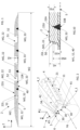
- FIG. 1 An example of a section of such a profile 2 intended to form a tread for a wheel tire, for example for a pneumatic tire, or even for a non-pneumatic tire within which the tread is supported by a mechanical element of the solid hub or spoke network type, is illustrated in the figure 1 .
- the receiving surface 5 is advantageously mounted to be mobile relative to the extrusion head 4, so as to be able to be driven in movement in the longitudinal direction X, and thus accompany the longitudinal progression of the profile 2, or even pull the profile 2, as said profile 2 is generated by coextrusion.
- the receiving surface 5 could be formed by a conveyor belt driven in translation in the direction longitudinal X relative to the extrusion head 4. According to this variant, the receiving surface 5 could form a flat surface.
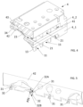
- the receiving surface 5 will be formed by a roller 6, and more particularly by the radially external surface of revolution of said roller 6, said roller 6 being driven in rotation relative to the extrusion head 4, around the central axis Y6 of said roller which is parallel to the lateral direction Y, and therefore perpendicular to the longitudinal direction X, as illustrated in the figure 2 .
- Said roller 6 will preferably form a straight cylinder, with a circular base.
- the longitudinal direction X may be likened to the “circumferential” direction, the lateral direction Y to the “axial” direction, and the vertical direction Z to the “radial” direction.
- the extrusion head 4 will preferably have a substantially conjugate shape, so as to cover the receiving surface 5 over a common overlapping zone defining the air gap 3.
- said extrusion head 4 will generally have a conjugate cylindrical shape, in an arc of a circle, preferably centered on the central axis Y6 of the roller 6.
- the profile 2 is advantageously generated continuously in the direction of its length, according to the longitudinal direction X.
- upstream and downstream will be understood here in consideration of the overall direction of flow of profile 2, which progresses from upstream to downstream in the longitudinal direction X.
- the extrusion head 4 comprises a first head portion 10 which is provided with one or more first intake channels 11 opening into the air gap 3 in order to bring into contact with the receiving surface 5 a first elastomeric mixture M1 intended to form a sub-layer 12 of the profile 2.
- said underlayer 12 is intended to come to bear on and around the crown reinforcement of the tire into which said tread will be integrated.
- the underlayer 12 extends, in the lateral direction Y, over a cumulative width which represents more than 80% of the width W2 of the profile 2, preferably more than 90% of the width W2 of the profile 2.
- said underlayer 12 may extend continuously over said cumulative width, or, in a preferred variant, be interrupted punctually at the locations receiving inserts 33, as will be explained below.
- the first elastomeric mixture M1 is a mixture based on unvulcanized rubber.
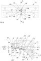
- the first head portion 10 also comprises, as is clearly visible in the figures 3 , 4 , 6 , 8 And 9A , at least one pre-scraper 13 which projects vertically into the air gap 3 while being delimited, in the lateral direction Y, by a first lateral face 13L and a second lateral face 13R, and, in the vertical direction Z, by a lower face 13B which faces the receiving surface 5 while being placed at a first predetermined, non-zero distance H13 from said receiving surface 5, called the “pre-scraping thickness” H13, such that said pre-scraper 13 can reserve, within the flow of the first elastomeric mixture M1, a trench 14 called the “burial trench” 14.
- said burial trench 14 is bordered on the one hand laterally by a first lateral sub-flow F1_M1 of said first elastomeric mixture and by a second lateral sub-flow F2_M1 of said first elastomeric mixture, first and second lateral sub-flows which flow on either side of the pre-scraper 13, respectively the first sub-flow F1_M1 along the first lateral face 13L and the second sub-flow F2_M1 along the second lateral face 13R of said pre-scraper 13, and on the other hand vertically by a bottom sub-flow F3_M1 which flows between the receiving surface 5 and the lower face 13B of the pre-scraper 13, in the pre-scraping thickness H13, to form a residual layer 15 of first elastomeric mixture M1.
- the pre-scraper 13 acts as a separator which splits the flow of first elastomeric mixture M1 into several sub-flows F1_M1, F2_M1, F3_M1 which bypass said pre-scraper 13 while the latter occupies the volume of the desired burial trench 14.
- the pre-scraping distance H13 will be less than or equal to 0.8 mm, and for example between 0.6 mm and 2 mm.
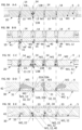
- the extrusion head 4 comprises a second head portion 20 which is provided with one or more second inlet channels 21 which open into the air gap 3 to bring a second elastomeric mixture M2 intended, as can be seen in the figures 1 , 8 And 9C , to cover the sub-layer 12 of first elastomeric mixture M1 from the first head portion 10.
- the second elastomeric mixture M2 is a mixture based on unvulcanized rubber.
- said second elastomeric mixture M2 will be intended to form sculpture blocks 22, which will come into contact with the roadway.
- the second head portion 20 comprises at least one scraper 23 which extends in the longitudinal extension of the pre-scraper 13, and which projects vertically into the air gap 3 so as to have a first lateral face 23L, a second lateral face 23R, as well as a lower face 23B which faces the receiving surface 5, at a second vertical distance H23 from said receiving surface, called “scraping thickness” H23, scraping thickness H23 which is strictly less than the pre-scraping thickness H13.
- scraper 23 which extends in the longitudinal extension of the pre-scraper 13, and which projects vertically into the air gap 3 so as to have a first lateral face 23L, a second lateral face 23R, as well as a lower face 23B which faces the receiving surface 5, at a second vertical distance H23 from said receiving surface, called “scraping thickness” H23, scraping thickness H23 which is strictly less than the pre-scraping thickness H13.
- said scraper 23 can laterally preserve the burial trench 14 by causing the flow of second elastomeric mixture M2 to form a first lateral sub-flow of second elastomeric mixture F1_M2 and a second lateral sub-flow of second elastomeric mixture F2_M2, which flow respectively along the first lateral face 23L of the scraper 23 for the first sub-flow F1_M2 and along the second lateral face 23R of said scraper 23 for the second sub-flow F2_M2, and which come in excess of the thickness respectively of the first lateral sub-flow of first mixture elastomeric F1_M1 and the second lateral sub-flow of first elastomeric mixture F2_M1 which come from the first head portion 10, while on the other hand said scraper 23 makes it possible to vertically dig the burial trench 14 by reducing, in accordance with the scraping thickness H23, the thickness of the residual layer 15 of first elastomeric mixture M1 at the bottom of said burial trench 14.
- the scraper 23 makes it possible to keep the burial trench 14 that was previously started by the pre-scraper 13 open, by maintaining, throughout the second head portion 20 in the flow direction X, a lateral gap on the one hand between the first lateral sub-flow of first elastomeric mixture F1_M1 and the second lateral sub-flow of first elastomeric mixture F2_M1 initially separated by the pre-scraper 13, and on the other hand a similar lateral gap between the first lateral sub-flow of second elastomeric mixture F1_M2 and the second lateral sub-flow of first elastomeric mixture F2_M2 which, in the second head portion 20, come to be superimposed on the lateral sub-flows of first elastomeric mixture F1_M1, F2_M1 to form an overlayer at least partially covering the underlayer 12.
- the scraper 23 further digs the burial trench to depth 14.
- the scraping distance H23 is chosen to be zero, so that, in the second head portion 20, the scraper 23, and more particularly the lower face 23B of said scraper 23, rubs against the receiving surface 5, so as to eliminate the residual layer of first elastomeric mixture M1 at the bottom of the burial trench 14.
- the progressiveness of the scraping ensured successively by a pre-scraper 13 then by a scraper 23 allows a gentle distribution and conformation of the sub-layer 12 of first elastomeric mixture M1, without excessive friction, which limits the energy consumption necessary for driving the receiving surface 5 and avoids any phenomenon of chattering or blocking of said receiving surface 5, and more particularly of the roller 6, and any phenomenon of jamming of the first elastomeric mixture M1 in the air gap 3, or any phenomenon of premature wear of the pre-scraper 13, of the scraper 23 or of the receiving surface 5.
- the scraper 23 may preferably have a friction pad intended to come into sliding contact against the receiving surface 5, said friction pad being made of a material which has a low coefficient of friction with respect to the material constituting the receiving surface 5.
- said friction pad may be made of a polymer of the PTFE (PolyTetraFluorEthylene), POM (PolyOxyMethylene) or PEEK (PolyEtherEtherKetone) type, or even of a copper-based metal alloy.
- the extrusion head 4 comprises a third head portion 30 comprising at least one injector 31 which projects into the air gap 3, in the longitudinal extension of the scraper 23, and which has an injection mouth 32 intended to inject a third elastomeric mixture M3, distinct from the second elastomeric mixture M2, to form an insert 33 in the burial trench 14.
- said insert 33 preferably constitutes a circumferential reinforcement, called a “corner”, which makes it possible to support the sculpture block 22 against lateral shear deformations, in order to improve the drift behavior of the bandage.
- the third elastomeric mixture M3 is a mixture based on unvulcanized rubber.
- the injector 31 being in the continuity of the scraper 23, said injector 31 makes it possible to deposit the third elastomeric mixture M3 inside, and more particularly on the bottom, of the burial trench 14, the volume of which has been cleared and shaped successively by the pre-scraper 13 then by the scraper 23 which precede said injector 31.
- the progressive digging and shaping of the burial trench 14 carried out by the pre-scraper 13 and then the scraper 23 make it possible to prepare in a precise, reproducible and clean manner the location intended for the installation of the insert 33.
- the injection mouth 32 and consequently the resulting section of the insert 33, has a triangular shape whose base 32B, 33B is oriented towards the receiving surface 5, and preferably rests on said receiving surface 5, and the top 32A, 33A of which is oriented towards the extrusion head 4.
- Such a triangular section in fact provides particularly rigid and stable support for the insert 33, which prevents the said insert 33 from tilting in the lateral direction Y and which therefore allows the said insert 33 to firmly support the tread block 22 against the shear forces in lateral drift, while allowing the said insert 33 to support well, without undergoing excessive deformation, the compressive stresses exerted by the roadway, via the tread block 22, in the vertical direction Z.
- Such a preferred arrangement advantageously provides a good, stable and rigid base for the insert 33, which can thus, in particular, in the case where the profile 2 constitutes a tread, rest directly on the crown reinforcement of the bandage, underlying said tread.
- the third head portion 30 further comprises, following the injector 31 in the longitudinal direction X, a cover wall 34 which extends over a predetermined length L34 called the “confluence length” L34 along the longitudinal direction X, from the injection mouth 32 to the outlet of the air gap 3, so that the flow of the profile 2 under said cover wall 34 allows the first lateral sub-flow of second elastomeric mixture F1_M2 and the second lateral sub-flow of second elastomeric mixture F2_M2 to close on the insert 33, thereby filling the burial trench 14.
- a cover wall 34 which extends over a predetermined length L34 called the “confluence length” L34 along the longitudinal direction X, from the injection mouth 32 to the outlet of the air gap 3, so that the flow of the profile 2 under said cover wall 34 allows the first lateral sub-flow of second elastomeric mixture F1_M2 and the second lateral sub-flow of second elastomeric mixture F2_M2 to close on the insert 33, thereby filling the burial trench 14.
- the insert 33 is perfectly integrated within the sculpture block 22 formed by said second elastomeric mixture M2, in a position which can be freely chosen, along the lateral direction Y, by determining the appropriate location of the injector 31 in said lateral direction Y.
- the shortest distance which separates, in the lateral direction Y, the insert 33 integrated into a sculpture block 22 from the lateral edge 22L, 22R of said sculpture block 22 which is closest to said insert 33 may be between 3 mm and 12 mm, and/or equal to or greater than 20%, or even 30% of the overall width of said sculpture block 22.
- the burial of the insert 33 substantially at mid-width of the tread block 22 allows the same insert 33 to laterally support said tread block 22 effectively in both directions, by limiting the shearing and tilting of the tread block 22 both to the left and to the right, which gives said tread block 22 better drift behavior.
- the base 33B of the insert 33 may thus preferably be located at a non-zero distance, and preferably substantially at the same non-zero distance, from each of said lateral edges 22L, 22R, as is notably visible in the figure 1 .
- the invention could be applied to the production of a profile 2 in which the top 33A of the insert 33 is flush with the upper surface 22U of the tread block 22 formed by the second elastomeric mixture M2.
- the height of the cover wall 34 considered in relation to the surface receiving 5 in the vertical direction Z, with the top 32A of the injection mouth 32, and therefore with the top 33A of the insert 33, such that the first lateral sub-flow of second elastomeric mixture F1_M2 would come into contact with one of the side walls of the insert 33 while the second lateral sub-flow of second elastomeric mixture F2_M2 would come into contact with the opposite side wall of said insert 33, and that the top 33A of the insert would mark the boundary between the first lateral sub-flow of second elastomeric mixture F1_M2 and the second lateral sub-flow of second elastomeric mixture F2_M2.
- the injector 31 is arranged so as to position the point 32A of the injection mouth 32, called the “top 32A of the injection mouth”, which is the furthest from the receiving surface 5, in the vertical direction Z, and which thus corresponds to the top 33A of the insert 33, at a non-zero vertical distance P31 from the cover wall 34, called the “burial depth” P31, such that the first lateral flow of second elastomeric mixture F1_M2 and the second lateral flow of second elastomeric mixture F2_M2 can join and merge in the space which is vertically between the top of the insert 33A and the cover wall 34, in order to bury said insert 33 in the second elastomeric mixture M2, at said predetermined burial depth P31.
- a junction of the first and second lateral sub-flows of second elastomeric mixture F1_M2, F2_M2 will preferably be carried out with each other, over the top 33A of the insert, so that this confluence of the first and second lateral sub-flows of second elastomeric mixture F1_M2, F2_M2 will have the effect not only of placing the second elastomeric mixture M2 in joint with the side walls of the insert 33 but also and above all, more generally, of covering the insert 33 under a layer of second elastomeric mixture M2 whose thickness, non-zero, corresponds to the burial depth P31.
- the distance which vertically separates the top 33A of the insert from the receiving surface 5 is therefore strictly less, here by a value equal to the burial depth P31, than the distance, corresponding here to the overall thickness H2 of the profile 2, which vertically separates the upper face 22U of the sculpture block 22 from said receiving surface 5 directly above said top 33A of the insert.
- the insert 33 is prevented from coming into direct contact with the roadway and thus interfering with the function assigned to the tread block 22.
- the burial depth P31 and therefore the vertical positioning of the insert 33 within the sculpture block 22, can be freely chosen by adapting the dimensions of the injector 31, and more generally by adapting the dimensions of the third head portion 30, so as to position the top 32A of the injection mouth 32 in vertical projection from the cover wall 34, by a value corresponding to the desired burial depth P31, so that the top 32A of the injection mouth 32 is at a distance from the receiving surface 5 which is less, in the vertical direction Z, than the distance which separates said receiving surface 5 from the cover wall 34.
- the burial depth P31 will preferably be between 3 mm and 8 mm, more preferably between 5 mm and 7 mm.
- the thickness H2 of said profile will preferably be between 6 mm and 12 mm.
- width W2 of profile 2 will preferably be between 150 mm and 350 mm.
- the height H33 of the top of the insert 33A relative to the receiving surface 5 represents between 30% and 60%, or even between 40% and 50%, of the height of the upper face 22U of the corresponding sculpture block 22, and more generally of the overall thickness H2 of the profile 2.
- the injection mouth 32 is located on the downstream face of the injector 31, that is to say on the trailing edge of said injector 31, which marks the point of confluence from which the lateral sub-flows of second elastomeric mixture F1_M2, F2_M2 and the flow of third elastomeric mixture M3 forming the insert 33 join.
- the base 32B of the injection mouth 32 is located slightly set back from the receiving surface 5 in the vertical direction Z, for example at a distance of between 0.5 mm and 0.8 mm from said receiving surface 5, in order to prevent the injector 31 from rubbing against the receiving surface 5.
- the base 32B of the injection mouth 32 will then preferably be completely open, so that the third elastomeric mixture M3 which emerges therefrom can come to rest directly against the bottom of the burial trench 14, and more particularly directly in contact with the receiving surface 5.
- the inventors have found that it is appropriate for said confluence length L34 to be on the one hand sufficiently long for the first and second lateral sub-flows of second elastomeric mixture F1_M2, F2_M2 to operate a satisfactory junction with the insert 33, and more particularly, when said lateral sub-flows of second elastomeric mixture come into contact with each other above the insert 33, so that said lateral sub-flows of second elastomeric mixture F1_M2, F2_M2 adhere perfectly to each other without leaving any zone of fragility or even crack (crack) at their joint plane, directly above the top 33A of the
- the confluence length L34 covered by the cover wall 34 is between 10 mm and 14 mm.
- This range of values is in particular applicable for a profile 2 whose overall thickness H2 is between 6 mm and 12 mm as indicated above, and whose height H33 of the top 33A of the insert 33, considered relative to the receiving surface 5, is equal to or preferably strictly less than said thickness H2, for example less than or equal to 60%, or less than 50%, of the thickness H2.
- the invention may in particular be applied to a profile whose thickness H2 is between 10 mm and 12 mm and whose insert(s) 33 will have a height H33 of between 5 mm and 7 mm.
- the inventors have also found that it would appear that the greater the height H33 of the insert 33, and therefore the thinner the thickness of the layer of second elastomeric mixture M2 which covers the top of the insert 33A, that is to say the lower the burial depth P31 (although not zero), the more necessary it is to provide a high confluence length L34 (which, here, tends towards, or even equals, 14 mm), whereas when the height H33 of the insert 33 is lower, and therefore when the burial depth P31 is greater, it is possible to reduce the confluence length L34 (here to make it tend towards, or even equal, 10 mm).
- the profile 2 leaves the air gap 3, and is thus released at ambient atmospheric pressure.
- the profile 2 can then cool and stabilize dimensionally on the continuation of the receiving surface 5, then on a conveyor (not shown), such as a roller or belt conveyor, which takes charge of said profile following the receiving surface 5.
- Said modules 4_1, 4_2 and blades 41, 42, 43 will be assembled and fixed to each other, preferably by screwing, and contiguously to each other in order to ensure the continuity of the extrusion head 4 in the longitudinal direction X.
- the first blade 41 preferably comprises teeth 44 which form terminal longitudinal extensions of the pre-scrapers 13, and can therefore be functionally assimilated to said pre-scrapers 13, teeth 44 which make it possible on the one hand to force the bottom sub-flow F3_M1, which forms the residual sub-layer 15 constituting the bottom of the burial trench 14, to substantially retain the pre-scraping thickness value H13 which was given to it by the pre-scraper 13 which precedes the tooth 44 considered, and on the other hand to distribute and refine the first and second lateral sub-flows of first elastomeric mixture F1_M1, F2_M1 on each side of said burial trench 14 so as to define a sub-layer bottom. 40 which is intended to receive the second elastomeric mixture M2 and thus to provide a fixing base for the sculpture blocks 22.
- the width of the pre-scraper 13, considered in the lateral direction Y increases in the upstream-downstream direction of the flow direction, as is clearly visible in the figure 3 .
- the pre-scraper 13 generally forms a divergent bow with respect to the flow direction, which makes it possible to gradually distribute the first elastomeric mixture M1 into the first lateral sub-flow F1_M1 and the second lateral sub-flow F2_M1.
- the free space which separates two neighboring pre-scrapers 13 in the lateral direction Y thus forms a funnel which causes the first elastomeric mixture M1 to converge towards the corresponding tooth 44 of the first blade 41, in order to promote a smooth conformation of the underlayer base 40 which will then be brought to support the sculpture blocks 22 in second elastomeric mixture M2.
- the scraper 23 has a convergent portion 23C which connects to the injector 31 and whose width, considered in the lateral direction Y, narrows in the upstream-downstream direction of the flow direction.
- the section of the scraper 23, and therefore of the burial trench 14 gradually narrows to gradually approach a width equal to, or close to, the width of the base 33B of the insert 33.
- This allows in particular the first and second lateral sub-flows of second elastomer mixture F1_M2, F2_M2 to operate, in the third head portion 30, a gentle and laminar junction with the flow of third elastomer mixture M3 forming the insert 33, without said first and second lateral sub-flows F1_M2, F2_M2 having to operate a sudden lateral detachment which could disrupt the proper flow of the flows or disturb the conformation of the insert 33.
- the maximum width of the scraper 23, and therefore of the burial trench 14, in the second head portion 20, at the upstream limit of the converging portion 23C of the scraper 23, may be chosen between two times and three times the width of the base 33B of the desired insert 33, for example equal to 2.6 times the width of the base 33B. Such proportions in fact make it possible to optimize the efficiency of the scraping.
- the maximum width of the scraper 23 may be substantially between two times and three times the width of the base 32B of the injection mouth 32.
- the invention will make it possible to use a first, a second and a third elastomeric mixture M1, M2, M3 which will have different compositions from each other, and therefore distinct mechanical properties, even if, preferably, all these elastomeric mixtures M1, M2, M3 will be based on unvulcanized rubber.
- the parameter used to characterize and select the elastomeric mixtures M1, M2, M3 will preferably be the complex dynamic shear modulus, noted G*.
- a third elastomeric material M3 will preferably be chosen, used for the inserts 33, whose complex dynamic shear modulus G*_M3 is strictly greater than that G*_M2 of the second elastomeric mixture M2, used here for the tread blocks 22.
- the complex dynamic shear modulus G*_M3 of the third elastomeric mixture M3 constituting the inserts 33 will preferably be strictly greater than that G*_M1 of the first elastomeric mixture M1 used for the underlayer 12.
- Said complex dynamic shear modulus G* is in fact representative of the rigidity of the elastomeric mixture considered, and characterizes the behavior of the elastomeric mixture considered when the latter is subjected to an alternating shear stress.
- Said complex dynamic shear modulus G* has, in representation in the complex plane, a real part, also called “elastic part” and noted G', which characterizes the elastic behavior of the mixture, and an imaginary part, also called “viscous part” and noted G'', which characterizes the dissipation of energy linked to the viscous behavior of the mixture.
- the viscoelastic loss Tg ⁇ and the complex dynamic shear modulus G* can be determined according to the ASTM D 5992-96 standard, by measuring the dynamic properties of the elastomeric mixture on a viscoanalyzer (here a Metravib VA4000 model). The measurement of the dynamic properties is carried out on a sample of vulcanized elastomeric mixture, here more particularly vulcanized under the curing conditions applicable to the bandage in the constitution of which the profile 2 enters, the sample having the shape of a cylindrical test piece having a thickness equal to 2 mm and a section equal to 78.5 mm 2 .
- a temperature scan is carried out at a constant temperature rise rate of +1.5°C/min.
- the glass transition temperature Tglass of the sample is in fact the temperature at which the dynamic loss Tg ⁇ reaches a maximum during the temperature scan.
- G* measured at 23°C, or where appropriate at 60°C is representative of the rigidity of the elastomeric mixture considered, i.e. its resistance to deformation, in particular its elastic deformation.
- the elastomeric compounds M1, M2, M3 may be chosen such that they have, in the vulcanized state, complex dynamic shear moduli respectively between 0.5 MPa and 5 MPa for the first elastomeric compound M1, between 0.9 MPa and 5 MPa for the second elastomeric compound M2, and between 40 MPa and 60 MPa for the third elastomeric compound M3, said complex dynamic shear moduli G* being measured here at 60°C according to the standard mentioned above.
- the invention of course relates as such to a method of manufacturing a profile 2, and more particularly a profile 2 intended to form a tire tread for a vehicle wheel.
- the invention relates in particular to a method for manufacturing a profile 2 during which a burial trench 14 is opened, by means of a pre-scraper 13, in a first elastomeric mixture M1 constituting a sub-layer 12 of the profile 2, then a second elastomeric mixture M2 is brought in to cover said sub-layer 12 while preserving, by means of a scraper 23, the burial trench 14 within the first and second elastomeric mixtures M1, M2, then a third elastomeric mixture M3 constituting an insert 33 is deposited in said burial trench 14, then the second elastomeric mixture M2 is allowed to fill said burial trench 14 in order to coat the insert 33.
- the second elastomeric mixture M2 comes, during this method, to cover the burial trench 14 and the insert 33 so as to bury the top of said insert 33 to a non-zero burial depth P31, preferably between 3 mm and 8 mm.
- the method is implemented to manufacture a profile 2 intended to form a tire tread for a vehicle wheel, profile 2 within which the first elastomeric mixture M1 forms a sub-layer 12 intended to be fixed to a crown reinforcement of the tire, the second elastomeric mixture M2 is intended to form tread blocks 22 coming into contact with the road, and the insert in third elastomeric mixture M3 is intended to form a circumferential reinforcement within the tread.
- the complex dynamic shear modulus G*_M3 of the third elastomeric mixture M3 is strictly greater than the complex dynamic shear modulus G*_M2 of the second elastomeric mixture M2.
- the elastomeric mixtures M1, M2, M3 may be chosen such that they exhibit complex dynamic shear moduli in the ranges of values indicated above.
- the method for manufacturing profile 2 described above preferably uses an installation 1 as described above to manufacture said profile 2.
- the invention relates to a method of manufacturing a tire for a vehicle wheel during which a profile 2 is manufactured according to the above profile manufacturing method, and said profile 2 is used to form the tread of said tire.
- this will allow the reinforcement insert 33 to fully fulfill, throughout the life of the bandage, its drift control function, without being exposed on the visible face of the tread and therefore without interfering with the road.
- the wear indicator 50 may preferably be obtained during the molding of the bandage in a vulcanization press, at the junction between the visible lateral edge 22L of a sculpture block 22 and the bottom of the circumferential groove 51 bordered by said sculpture block 22, as can be seen in the figure. figure 10 , by conforming said side edge 22L in said vulcanization press.
- auxiliary reinforcements 52 for example of triangular section, to certain sculpture blocks 22, as indicated in dotted lines on the figure. figure 1 .
- the profile 2 may be produced such that said profile 2 comprises at least one tread block 22 which is delimited in the lateral direction Y by at least one lateral edge 22L, 22R and which comprises an insert 33 buried in said tread block 22 at a distance from said at least one lateral edge 22L, 22R, and an auxiliary reinforcement 52, preferably of triangular section, will be added against said at least one lateral edge 22L, 22R of the tread block 22.
- the height of the top of the auxiliary reinforcement 52 will be strictly greater than the height H33 of the top of the buried insert 33, and more preferably, the top of the auxiliary reinforcement 52 will be flush with the upper face 22U of the sculpture block 22.
- the base of the auxiliary reinforcement 52 will rest directly on the sub-layer 12 made of first elastomeric mixture M1. More preferably, the base of the auxiliary reinforcement 52 will preferably rest on a so-called “intermediate” portion of the sub-layer 12 made of first elastomeric mixture M1, an intermediate portion of sub-layer which ensures, in the lateral direction Y, the continuity of the sub-layer 12 with the sub-layer bottoms 40 serving as bases for the tread blocks 22, and in particular the continuity of the sub-layer 12 under the grooves 51.
- the thickness of the sub-layer 12 may be less, in the intermediate portion(s) located under the auxiliary reinforcement(s) 52 and/or at the bottom of the groove(s) 51, than the thickness that said sub-layer 12 has in the sub-layer bottoms 40 which carry the tread blocks 22.
- the auxiliary reinforcement 52 will be formed in an elastomeric mixture, preferably based on raw rubber, which has, once vulcanized, a modulus dynamic shear complex G* strictly greater than that G*_M2 of the second elastomeric mixture M2 constituting the sculpture block 22, in order to present greater stiffness, and thus to be able to contribute to supporting and stiffening the sculpture block 22 against lateral drift.
- the complex dynamic shear modulus G* of the auxiliary reinforcement 52 will be strictly greater than that G*_M1 of the first elastomeric mixture M1 constituting the sub-layer 12.
- the auxiliary reinforcement 52 may be added to the raw profile 2, after said profile 2 has been produced by coextrusion, by integrating, for example by rolling, said auxiliary reinforcement 52 in the location reserved for this purpose in the profile 2, against the lateral edge 22L, 22R of the sculpture block 22 concerned. The assembly will then be vulcanized, during the curing of the bandage.
- the combination of an insert 33 buried in the sculpture block 22 and a lateral auxiliary reinforcement 52 placed at the interface between said sculpture block 22 and the circumferential groove 51 makes it possible to optimize the drift behavior of the sculpture block 22 concerned.
- the invention as such also relates to a profile 2 obtained as indicated above, and to a bandage, in particular a pneumatic bandage, provided with such a profile 2.
- the invention may relate to a profile 2 comprising one or more inserts 33 each buried in a sculpture block 22, to a profile 2 called an “improved profile” combining one or more inserts 33 each buried in a sculpture block 22 with one or more auxiliary reinforcements 52 as described above, as well as, finally, to a tire for a vehicle wheel comprising a tread formed by such an improved profile 2.
Landscapes
- Engineering & Computer Science (AREA)
- Mechanical Engineering (AREA)
- Manufacturing & Machinery (AREA)
- Extrusion Moulding Of Plastics Or The Like (AREA)
- Tyre Moulding (AREA)
Claims (15)
- Anlage (1) zur Koextrusion, die dazu bestimmt ist, ein Profil (2) zu erzeugen, indem eine Mehrzahl von Elastomermischungen (M1, M2, M3) zusammen entlang einer gemeinsamen Fließrichtung extrudiert werden, die der Längsrichtung (X) des Profils (2) entspricht, wobei die Anlage einen Extrusionskopf (4) umfasst, der die Elastomermischungen (M1, M2, M3) zuführt, sowie eine Aufnahmefläche (5) wie etwa eine Walze (6), die gegenüber dem Extrusionskopf (4) platziert ist, um einen Spalt (3) zu definieren, der dazu dient, den Querschnitt des Profils (2) in der Dicke (H2) entlang einer Richtung, "vertikale Richtung" (Z) genannt, die senkrecht zu der Längsrichtung (X) und zu der Aufnahmefläche (5) ist, und in der Breite (W2) entlang einer Richtung, "seitliche Richtung" (Y) genannt, die senkrecht zu der Längsrichtung (X) und zu der vertikalen Richtung (Z) ist, zu formen, wobei die Anlage (1) dadurch gekennzeichnet ist, dass der Extrusionskopf (4) von stromauf nach stromab entlang der Fließrichtung umfasst:- zunächst einen ersten Kopfabschnitt (10), der mit einem oder mehreren ersten Zuführkanälen (11) versehen ist, die sich in dem Spalt (3) öffnen, um im Kontakt mit der Aufnahmefläche (5) eine erste Elastomermischung (M1) zuzuführen, die dazu bestimmt ist, eine Teilschicht (12) des Profils (2) zu bilden, wobei der erste Kopfabschnitt (10) auch mindestens einen Vorabstreifer (13) umfasst, der vertikal in den Spalt (3) hineinragt, wobei er entlang der seitlichen Richtung (Y) durch eine erste seitliche Fläche (13L) und eine zweite seitliche Fläche (13R) begrenzt wird und entlang der vertikalen Richtung (Z) durch eine untere Fläche (13B), die der Aufnahmefläche (5) zugewandt ist, wobei sie in einem ersten vorbestimmten Abstand (H13) ungleich null von der Aufnahmefläche, "Vorabstreifdicke" (H13) genannt, platziert ist, so dass der Vorabstreifer (13) in dem Strom der ersten Elastomermischung (M1) einen Graben, "Einbindegraben" (14) genannt, aussparen kann, der zum einen seitlich von einem ersten seitlichen Teilstrom (F1_M1) der ersten Elastomermischung (M1) und von einem zweiten seitlichen Teilstrom (F2_M1) der ersten Elastomermischung (M1), erste und zweite seitliche Teilströme (F1_M1, F2_M1), gesäumt wird, die beidseits des Vorabstreifers (13) entlang der ersten seitlichen Fläche (13L) beziehungsweise entlang der zweiten seitlichen Fläche (13R) des Vorabstreifers fließen, und zum anderen vertikal von einem Bodenteilstrom (F3_M1), der zwischen der Aufnahmefläche (5) und der unteren Fläche (13B) des Vorabstreifers (13), in der Vorabstreifdicke (H13), fließt, um eine Restschicht (15) aus erster Elastomermischung (M1) zu bilden,- dann einen zweiten Kopfabschnitt (20), der mit einem oder mehreren zweiten Zuführkanälen (21) versehen ist, die sich in dem Spalt (3) öffnen, um eine zweite Elastomermischung (M2) zuzuführen, die dazu bestimmt ist, die Teilschicht (12) aus der ersten Elastomermischung (M1), die aus dem ersten Kopfabschnitt (10) hervorgegangen ist, zu bedecken, wobei der zweite Kopfabschnitt mindestens einen Abstreifer (23) umfasst, der sich in der Längsverlängerung des Vorabstreifers (13) erstreckt und der vertikal in den Spalt (3) hineinragt, so dass er eine erste seitliche Fläche (23L), eine zweite seitliche Fläche (23R) sowie eine untere Fläche (23B), die der Aufnahmefläche (5) zugewandt ist, in einem zweiten vertikalen Abstand (H23) von der Aufnahmefläche (5), "Abstreifdicke" (H23) genannt, die strikt kleiner als die Vorabstreifdicke (H13) ist, aufweist, so dass zum einen der Abstreifer (23) den Einbindegraben (14) seitlich bewahren kann, indem er den Strom der zweiten Elastomermischung (M2) so zuführt, dass ein erster seitlicher Teilstrom aus der zweiten Elastomermischung (F1_M2) und ein zweiter seitlicher Teilstrom aus der zweiten Elastomermischung (F2_M2) gebildet werden, die entlang der ersten seitlichen Fläche (23L) beziehungsweise entlang der zweiten seitlichen Fläche (23R) des Abstreifers fließen und die als Überdicke des ersten beziehungsweise des zweiten seitlichen Teilstroms aus der ersten Elastomermischung (F1_M1, F2_M1), die aus dem ersten Kopfabschnitt (10) hervorgegangen sind, angeordnet sind, während zum anderen der Abstreifer (23) es ermöglicht, den Einbindegraben (14) vertikal auszuhöhlen, indem gemäß der Abstreifdicke (H23) die Dicke der Restschicht aus der ersten Elastomermischung (M1) am Boden des Einbindegrabens (14) reduziert wird,- dann einen dritten Kopfabschnitt (30), der mindestens einen Injektor (31) umfasst, der in den Spalt (3) in der Längsverlängerung des Abstreifers (23) hineinragt und der eine Injektionsmündung (32) besitzt, die dazu bestimmt ist, eine dritte Elastomermischung (M3), die von der zweiten Elastomermischung (M2) verschieden ist, zu injizieren, um eine Einlage (33) in dem Einbindegraben (14) zu bilden, wobei der dritte Kopfabschnitt (30) ferner, nach dem Injektor (31) in der Längsrichtung (X), eine Abdeckwand (34) umfasst, die sich über eine vorbestimmte Länge, "Konfluenzlänge" (L34) genannt, entlang der Längsrichtung (X) von der Injektionsmündung (32) bis zum Auslass des Spalts (3) erstreckt, damit das Fließen des Profils (2) unter der Abdeckwand (34) es den ersten und zweiten seitlichen Teilströmen aus der zweiten Elastomermischung (F1_M2, F2_M2) ermöglicht, sich auf der Einlage (33) zu schließen und so den Einbindegraben (14) auszufüllen.
- Anlage nach Anspruch 1, dadurch gekennzeichnet, dass der Abstreifabstand (H23) gleich null ist, so dass, in dem zweiten Kopfabschnitt (20), der Abstreifer (23) gegen die Aufnahmefläche (5) reibt, so dass die Restschicht aus der ersten Elastomermischung (M1) am Boden des Einbindegrabens (14) entfernt wird, um es dem Injektor (31) des dritten Kopfabschnitts (30) zu ermöglichen, die Einlage (33) aus der dritten Elastomermischung (M3) in Kontakt mit der Aufnahmefläche (5) abzulegen.
- Anlage nach Anspruch 1 oder 2, dadurch gekennzeichnet, dass der Injektor (31) so gestaltet ist, dass der Punkt der Injektionsmündung (32), der am weitesten von der Aufnahmefläche (5) entlang der vertikalen Richtung (Z)entfernt ist und der somit dem Scheitelpunkt der Einlage (33A) entspricht, in einem vertikalen Abstand ungleich null von der Abdeckwand (34), "Einbindungstiefe" (P31) genannt, positioniert ist, so dass der erste seitliche Strom aus der zweiten Elastomermischung (F1_M2) und der zweite seitliche Strom aus der zweiten Elastomermischung (F2_M2) zusammentreffen und in dem Raum, der vertikal zwischen dem Scheitelpunkt der Einlage (33A) und der Abdeckwand (34) enthalten ist, verschmelzen können, um die Einlage (33) in der zweiten Elastomermischung (M2) in der Einbindetiefe (P31) einzubinden.
- Anlage nach Anspruch 3, dadurch gekennzeichnet, dass die Einbindetiefe (P31) zwischen 3 mm und 8 mm, vorzugsweise zwischen 5 mm und 7 mm beträgt.
- Anlage nach einem der vorhergehenden Ansprüche, dadurch gekennzeichnet, dass die Konfluenzlänge (L34), die von der Abdeckwand (34) bedeckt wird, zwischen 10 mm und 14 mm beträgt.
- Anlage nach einem der vorhergehenden Ansprüche, dadurch gekennzeichnet, dass in dem ersten Kopfabschnitt (10) die Breite des Vorabstreifers (13), entlang der seitlichen Richtung (Y) betrachtet, im Stromauf-Stromab-Richtungssinn der Fließrichtung zunimmt.
- Anlage nach einem der vorhergehenden Ansprüche, dadurch gekennzeichnet, dass in dem zweiten Kopfabschnitt (20) der Abstreifer (23) einen konvergierenden Abschnitt (23C) aufweist, der an den Injektor (31) anschließt und dessen Breite sich, entlang der seitlichen Richtung (Y) betrachtet, im Stromauf-Stromab-Richtungssinn der Fließrichtung verjüngt.
- Anlage nach einem der vorhergehenden Ansprüche, dadurch gekennzeichnet, dass die Injektionsmündung (32) und infolgedessen der resultierende Querschnitt der Einlage (33) eine dreieckige Form aufweist, deren Grundseite (33B) zu der Aufnahmefläche (5) hin und deren Scheitelpunkt (33A) zu dem Extrusionskopf (4) hin ausgerichtet ist.
- Anlage nach einem der vorhergehenden Ansprüche, dadurch gekennzeichnet, dass die Aufnahmefläche (5) durch ein Förderband gebildet wird, das translatorisch entlang der Längsrichtung (X) in Bezug auf den Extrusionskopf (4) angetrieben wird, oder, stärker bevorzugt, durch eine Walze (6), die in Bezug auf den Extrusionskopf (4) um ihre Mittelachse (Y6) drehangetrieben wird, die parallel zu der seitlichen Richtung (Y) ist.
- Verfahren zur Herstellung eines Profils (2), dadurch gekennzeichnet, dass man mittels eines Vorabstreifers (13) einen Einbindegraben (14) in einer ersten Elastomermischung (M1) bildet, aus der eine Teilschicht (12) des Profils (2) besteht, man dann eine zweite Elastomermischung (M2) zuführt, um die Teilschicht (12) zu bedecken, wobei dank eines Abstreifers (23) der Einbindegraben (14) in den ersten und zweiten Elastomermischungen (M1, M2) beibehalten wird, man dann in dem Einbindegraben (14) eine dritte Elastomermischung (M3) aufbringt, aus der eine Einlage (33) besteht, man dann die zweite Elastomermischung (M2) den Einbindegraben (14) ausfüllen lässt, um die Einlage (33) zu umhüllen.
- Verfahren nach Anspruch 10, dadurch gekennzeichnet, dass die zweite Elastomermischung (M2) den Einbindegraben (14) und die Einlage (33) so bedeckt, dass der Scheitelpunkt der Einlage (33) in einer Einbindetiefe (P31) ungleich null, vorzugsweise zwischen 3 mm und 8 mm, eingebunden wird.
- Verfahren nach Anspruch 10 oder 11, dadurch gekennzeichnet, dass das Profil (2) dazu bestimmt ist, einen Laufstreifen eines Reifens für ein Fahrzeugrad zu bilden, dass, in dem Profil (2), die erste Elastomermischung (M1) eine Teilschicht (12) bildet, die auf einer Scheitelverstärkung des Reifens fixiert wird, die zweite Elastomermischung (M2) dazu bestimmt ist, Profilblöcke (22) zu bilden, die in Kontakt mit der Fahrbahn gelangen, und die Einlage (33) aus der dritten Elastomermischung (M3) dazu bestimmt ist, einen umfänglichen Festigkeitsträger in dem Laufstreifen zu bilden, und dadurch, dass der komplexe dynamische Schubmodul (G*_M3) der dritten Elastomermischung (M3) strikt größer als der komplexe dynamische Schubmodul (G*_M2) der zweite Elastomermischung (M2) ist.
- Verfahren zur Herstellung eines Reifens für ein Fahrzeugrad, bei dem nach dem Verfahren des Anspruchs 12 ein Profil (2) hergestellt wird und das Profil (2) verwendet wird, um den Laufstreifen des Reifens zu bilden.
- Verfahren zur Herstellung eines Reifens für ein Fahrzeugrad nach Anspruch 13, dadurch gekennzeichnet, dass man in mindestens einen der Profilblöcke (22), die in der zweiten Elastomermischung (M2) gebildet sind, mindestens einen Verschleißanzeiger (50) einarbeitet, der es ermöglicht, den Verschleißzustand des Reifens zu überwachen, und dadurch, dass der Scheitelpunkt (33A) der Einlage (33), die aus der dritte Elastomermischung (M3) gebildet wird, eine Höhe (H33) in Bezug auf die Aufnahmefläche (5) und entlang der vertikalen Richtung (Z) aufweist, die strikt kleiner als die Höhe (H50) des Verschleißanzeigers (50) ist, so dass, wenn der Reifen in Betrieb ist, man zu dem Verschleißanzeiger (50) gelangt, bevor man den Scheitelpunkt (33A) der in den mindestens einen der Profilblöcke (22) eingebundenen Einlage freilegt.
- Verfahren zur Herstellung eines Reifens für ein Fahrzeugrad nach Anspruch 13 oder 14, dadurch gekennzeichnet, dass das ausgeführte Profil (2) mindestens einen Profilblock (22) umfasst, der entlang der seitlichen Richtung (Y) durch mindestens einen seitlichen Rand (22L, 22R) begrenzt wird und der eine Einlage (33) umfasst, die in den Profilblock (22) im Abstand von dem mindestens einen seitlichen Rand (22L, 22R) eingebunden ist, und dadurch, dass man einen Hilfsfestigkeitsträger (52), bevorzugt mit dreieckigem Querschnitt, gegen den mindestens einen seitlichen Rand (22L, 22R) des Profilblocks (22) hinzufügt.
Applications Claiming Priority (2)
| Application Number | Priority Date | Filing Date | Title |
|---|---|---|---|
| FR2012249A FR3116751B1 (fr) | 2020-11-27 | 2020-11-27 | Installation de coextrusion permettant de realiser une bande de roulement presentant des inserts de renfort enfouis en profondeur dans les blocs de sculpture |
| PCT/FR2021/051527 WO2022112666A1 (fr) | 2020-11-27 | 2021-09-07 | Installation de coextrusion permettant de realiser une bande de roulement presentant des inserts de renfort enfouis en profondeur dans les blocs de sculpture |
Publications (2)
| Publication Number | Publication Date |
|---|---|
| EP4251397A1 EP4251397A1 (de) | 2023-10-04 |
| EP4251397B1 true EP4251397B1 (de) | 2025-01-22 |
Family
ID=74206047
Family Applications (1)
| Application Number | Title | Priority Date | Filing Date |
|---|---|---|---|
| EP21778188.9A Active EP4251397B1 (de) | 2020-11-27 | 2021-09-07 | Koextrusionsanlage und verfahren zur herstellung einer lauffläche mit in der tiefe in den laufflächenprofilblöcken eingebetteten verstärkungseinlagen |
Country Status (4)
| Country | Link |
|---|---|
| US (1) | US20240034015A1 (de) |
| EP (1) | EP4251397B1 (de) |
| FR (1) | FR3116751B1 (de) |
| WO (1) | WO2022112666A1 (de) |
Families Citing this family (1)
| Publication number | Priority date | Publication date | Assignee | Title |
|---|---|---|---|---|
| IT202200013540A1 (it) * | 2022-06-27 | 2023-12-27 | Wittur Holding Gmbh | Rotella per operatore porta di un ascensore |
Citations (1)
| Publication number | Priority date | Publication date | Assignee | Title |
|---|---|---|---|---|
| WO2017109392A1 (fr) * | 2015-12-23 | 2017-06-29 | Compagnie Generale Des Etablissements Michelin | Procede de coextrusion d'un profile caoutchouteux complexe destine a la fabrication d'un pneumatique |
Family Cites Families (5)
| Publication number | Priority date | Publication date | Assignee | Title |
|---|---|---|---|---|
| FR2964344B1 (fr) * | 2010-09-02 | 2012-08-31 | Michelin Soc Tech | Bandage pneumatique avec une bande de roulement comportant un materiau de remplissage degradable |
| WO2017146734A1 (en) * | 2016-02-26 | 2017-08-31 | Compagnie Generale Des Etablissements Michelin | Roller nose extruder with die plate for extrusion of multiple material product |
| WO2018002487A1 (fr) | 2016-06-27 | 2018-01-04 | Compagnie Generale Des Etablissements Michelin | Pneumatique avec une bande de roulement comportant des elements de renforcement |
| EP3645236B1 (de) | 2017-06-30 | 2021-04-07 | Compagnie Générale des Etablissements Michelin | Extrusionskopf mit kanälen zur herstellung von einsätzen in einem profilband zur herstellung eines luftreifens und entsprechendes extrusionsverfahren |
| FR3072896A1 (fr) | 2017-10-27 | 2019-05-03 | Compagnie Generale Des Etablissements Michelin | Tete d’extrusion d’un profile complexe forme de profiles juxtaposes |
-
2020
- 2020-11-27 FR FR2012249A patent/FR3116751B1/fr active Active
-
2021
- 2021-09-07 WO PCT/FR2021/051527 patent/WO2022112666A1/fr not_active Ceased
- 2021-09-07 US US18/038,635 patent/US20240034015A1/en active Pending
- 2021-09-07 EP EP21778188.9A patent/EP4251397B1/de active Active
Patent Citations (1)
| Publication number | Priority date | Publication date | Assignee | Title |
|---|---|---|---|---|
| WO2017109392A1 (fr) * | 2015-12-23 | 2017-06-29 | Compagnie Generale Des Etablissements Michelin | Procede de coextrusion d'un profile caoutchouteux complexe destine a la fabrication d'un pneumatique |
Also Published As
| Publication number | Publication date |
|---|---|
| WO2022112666A1 (fr) | 2022-06-02 |
| FR3116751A1 (fr) | 2022-06-03 |
| US20240034015A1 (en) | 2024-02-01 |
| EP4251397A1 (de) | 2023-10-04 |
| FR3116751B1 (fr) | 2022-11-04 |
Similar Documents
| Publication | Publication Date | Title |
|---|---|---|
| EP3448645B1 (de) | Formvorrichtung zum formen einer haltevorrichtung | |
| FR2961741A1 (fr) | Lamelle pour une garniture d'un moule destine a la vulcanisation d'une bande de roulement d'un pneumatique | |
| EP2790905B1 (de) | Formteil mit schneidemitteln zum formen und vulkanisieren einer reifenlauffläche | |
| EP4251397B1 (de) | Koextrusionsanlage und verfahren zur herstellung einer lauffläche mit in der tiefe in den laufflächenprofilblöcken eingebetteten verstärkungseinlagen | |
| EP1638785B1 (de) | Schutzrippe für eine reifenlauffläche | |
| FR3000424A1 (fr) | Element de moule comportant des moyens de decoupe pour le moulage et la vulcanisation d'une bande de roulement d'un pneumatique | |
| EP2794248B1 (de) | Formteil mit schneidvorrichtung zum formen und vulkanisieren einer reifenlauffläche | |
| EP2782748A1 (de) | Form mit einem hohlraum zum formen einer vorrichtung zum verschliessen in einer nut | |
| FR2753248A1 (fr) | Procede de fabrication d'une courroie de transmission et courroie obtenue par ce procede | |
| EP3645236B1 (de) | Extrusionskopf mit kanälen zur herstellung von einsätzen in einem profilband zur herstellung eines luftreifens und entsprechendes extrusionsverfahren | |
| EP3700731B1 (de) | Kopf zum extrudieren eines komplexen profils aus nebeneinanderliegenden profilen | |
| EP4251398B1 (de) | Verfahren zur herstellung einer lauffläche durch koextrusion mit integration einer entkopplungsschnittstelle zwischen laufflächenprofilblöcken und verstärkungskeilen | |
| CA2599845C (fr) | Procede de moulage d'un boyau profile sur un vitrage | |
| EP1586438A1 (de) | Reifenform und mit dieser Reifenform hergestellter Reifenlaufstreifen | |
| EP4330026B1 (de) | Vorrichtung und verfahren zum schneiden eines zwischenprodukts aus kautschuk | |
| FR3090485A1 (fr) | Bande de roulement de pneu pour poids lourd ayant des incisions améliorées. | |
| WO2025132590A1 (fr) | Plaquette à granulométrie variable | |
| FR3068281A1 (fr) | Procede d'extrusion d'un profile complexe comprenant une gomme de bordure en fond de sillon | |
| FR3128395A1 (fr) | Installation de coextrusion comprenant des cordons d’étanchéité qui sont écrasés contre le rouleau lors de la fermeture de la tête d’extrusion | |
| FR3068280A1 (fr) | Tete d'extrusion d'un profile complexe comprenant un insert | |
| FR3114040A1 (fr) | Moule pour la réalisation d’une pièce en matériau de moulage | |
| FR3068279A1 (fr) | Tete d'extrusion d'un profile complexe comprenant une gomme de bordure en fond de sillon | |
| EP1637402A1 (de) | Kraftfahrzeugboden mit einem Unterteil einer Stirnwand | |
| FR3068278A1 (fr) | Procede d'extrusion d'un profile complexe comprenant un insert |
Legal Events
| Date | Code | Title | Description |
|---|---|---|---|
| STAA | Information on the status of an ep patent application or granted ep patent |
Free format text: STATUS: UNKNOWN |
|
| STAA | Information on the status of an ep patent application or granted ep patent |
Free format text: STATUS: THE INTERNATIONAL PUBLICATION HAS BEEN MADE |
|
| PUAI | Public reference made under article 153(3) epc to a published international application that has entered the european phase |
Free format text: ORIGINAL CODE: 0009012 |
|
| STAA | Information on the status of an ep patent application or granted ep patent |
Free format text: STATUS: REQUEST FOR EXAMINATION WAS MADE |
|
| 17P | Request for examination filed |
Effective date: 20230627 |
|
| AK | Designated contracting states |
Kind code of ref document: A1 Designated state(s): AL AT BE BG CH CY CZ DE DK EE ES FI FR GB GR HR HU IE IS IT LI LT LU LV MC MK MT NL NO PL PT RO RS SE SI SK SM TR |
|
| DAV | Request for validation of the european patent (deleted) | ||
| DAX | Request for extension of the european patent (deleted) | ||
| RIC1 | Information provided on ipc code assigned before grant |
Ipc: B29C 48/07 20190101ALN20240313BHEP Ipc: B60C 11/24 20060101ALN20240313BHEP Ipc: B29D 30/52 20060101ALN20240313BHEP Ipc: B29C 48/305 20190101ALI20240313BHEP Ipc: B29C 48/30 20190101ALI20240313BHEP Ipc: B29C 48/12 20190101ALI20240313BHEP Ipc: B29C 48/49 20190101ALI20240313BHEP Ipc: B29C 48/21 20190101ALI20240313BHEP Ipc: B29C 48/35 20190101AFI20240313BHEP |
|
| GRAP | Despatch of communication of intention to grant a patent |
Free format text: ORIGINAL CODE: EPIDOSNIGR1 |
|
| STAA | Information on the status of an ep patent application or granted ep patent |
Free format text: STATUS: GRANT OF PATENT IS INTENDED |
|
| RIC1 | Information provided on ipc code assigned before grant |
Ipc: B29C 48/07 20190101ALN20240321BHEP Ipc: B60C 11/24 20060101ALN20240321BHEP Ipc: B29D 30/52 20060101ALN20240321BHEP Ipc: B29C 48/305 20190101ALI20240321BHEP Ipc: B29C 48/30 20190101ALI20240321BHEP Ipc: B29C 48/12 20190101ALI20240321BHEP Ipc: B29C 48/49 20190101ALI20240321BHEP Ipc: B29C 48/21 20190101ALI20240321BHEP Ipc: B29C 48/35 20190101AFI20240321BHEP |
|
| INTG | Intention to grant announced |
Effective date: 20240419 |
|
| GRAJ | Information related to disapproval of communication of intention to grant by the applicant or resumption of examination proceedings by the epo deleted |
Free format text: ORIGINAL CODE: EPIDOSDIGR1 |
|
| STAA | Information on the status of an ep patent application or granted ep patent |
Free format text: STATUS: REQUEST FOR EXAMINATION WAS MADE |
|
| INTC | Intention to grant announced (deleted) | ||
| RAP3 | Party data changed (applicant data changed or rights of an application transferred) |
Owner name: COMPAGNIE GENERALE DES ETABLISSEMENTS MICHELIN |
|
| GRAP | Despatch of communication of intention to grant a patent |
Free format text: ORIGINAL CODE: EPIDOSNIGR1 |
|
| STAA | Information on the status of an ep patent application or granted ep patent |
Free format text: STATUS: GRANT OF PATENT IS INTENDED |
|
| RIC1 | Information provided on ipc code assigned before grant |
Ipc: B29C 48/07 20190101ALN20240807BHEP Ipc: B60C 11/24 20060101ALN20240807BHEP Ipc: B29D 30/52 20060101ALN20240807BHEP Ipc: B29C 48/305 20190101ALI20240807BHEP Ipc: B29C 48/30 20190101ALI20240807BHEP Ipc: B29C 48/12 20190101ALI20240807BHEP Ipc: B29C 48/49 20190101ALI20240807BHEP Ipc: B29C 48/21 20190101ALI20240807BHEP Ipc: B29C 48/35 20190101AFI20240807BHEP |
|
| RIC1 | Information provided on ipc code assigned before grant |
Ipc: B29C 48/07 20190101ALN20240812BHEP Ipc: B60C 11/24 20060101ALN20240812BHEP Ipc: B29D 30/52 20060101ALN20240812BHEP Ipc: B29C 48/305 20190101ALI20240812BHEP Ipc: B29C 48/30 20190101ALI20240812BHEP Ipc: B29C 48/12 20190101ALI20240812BHEP Ipc: B29C 48/49 20190101ALI20240812BHEP Ipc: B29C 48/21 20190101ALI20240812BHEP Ipc: B29C 48/35 20190101AFI20240812BHEP |
|
| INTG | Intention to grant announced |
Effective date: 20240909 |
|
| GRAS | Grant fee paid |
Free format text: ORIGINAL CODE: EPIDOSNIGR3 |
|
| GRAA | (expected) grant |
Free format text: ORIGINAL CODE: 0009210 |
|
| STAA | Information on the status of an ep patent application or granted ep patent |
Free format text: STATUS: THE PATENT HAS BEEN GRANTED |
|
| AK | Designated contracting states |
Kind code of ref document: B1 Designated state(s): AL AT BE BG CH CY CZ DE DK EE ES FI FR GB GR HR HU IE IS IT LI LT LU LV MC MK MT NL NO PL PT RO RS SE SI SK SM TR |
|
| REG | Reference to a national code |
Ref country code: GB Ref legal event code: FG4D Free format text: NOT ENGLISH |
|
| REG | Reference to a national code |
Ref country code: CH Ref legal event code: EP |
|
| REG | Reference to a national code |
Ref country code: IE Ref legal event code: FG4D Free format text: LANGUAGE OF EP DOCUMENT: FRENCH |
|
| REG | Reference to a national code |
Ref country code: DE Ref legal event code: R096 Ref document number: 602021025155 Country of ref document: DE |
|
| REG | Reference to a national code |
Ref country code: NL Ref legal event code: MP Effective date: 20250122 |
|
| PG25 | Lapsed in a contracting state [announced via postgrant information from national office to epo] |
Ref country code: NL Free format text: LAPSE BECAUSE OF FAILURE TO SUBMIT A TRANSLATION OF THE DESCRIPTION OR TO PAY THE FEE WITHIN THE PRESCRIBED TIME-LIMIT Effective date: 20250122 |
|
| PG25 | Lapsed in a contracting state [announced via postgrant information from national office to epo] |
Ref country code: RS Free format text: LAPSE BECAUSE OF FAILURE TO SUBMIT A TRANSLATION OF THE DESCRIPTION OR TO PAY THE FEE WITHIN THE PRESCRIBED TIME-LIMIT Effective date: 20250422 |
|
| PG25 | Lapsed in a contracting state [announced via postgrant information from national office to epo] |
Ref country code: FI Free format text: LAPSE BECAUSE OF FAILURE TO SUBMIT A TRANSLATION OF THE DESCRIPTION OR TO PAY THE FEE WITHIN THE PRESCRIBED TIME-LIMIT Effective date: 20250122 |
|
| PG25 | Lapsed in a contracting state [announced via postgrant information from national office to epo] |
Ref country code: PL Free format text: LAPSE BECAUSE OF FAILURE TO SUBMIT A TRANSLATION OF THE DESCRIPTION OR TO PAY THE FEE WITHIN THE PRESCRIBED TIME-LIMIT Effective date: 20250122 |
|
| PG25 | Lapsed in a contracting state [announced via postgrant information from national office to epo] |
Ref country code: ES Free format text: LAPSE BECAUSE OF FAILURE TO SUBMIT A TRANSLATION OF THE DESCRIPTION OR TO PAY THE FEE WITHIN THE PRESCRIBED TIME-LIMIT Effective date: 20250122 |
|
| REG | Reference to a national code |
Ref country code: LT Ref legal event code: MG9D |
|
| PG25 | Lapsed in a contracting state [announced via postgrant information from national office to epo] |
Ref country code: IS Free format text: LAPSE BECAUSE OF FAILURE TO SUBMIT A TRANSLATION OF THE DESCRIPTION OR TO PAY THE FEE WITHIN THE PRESCRIBED TIME-LIMIT Effective date: 20250522 Ref country code: NO Free format text: LAPSE BECAUSE OF FAILURE TO SUBMIT A TRANSLATION OF THE DESCRIPTION OR TO PAY THE FEE WITHIN THE PRESCRIBED TIME-LIMIT Effective date: 20250422 |
|
| REG | Reference to a national code |
Ref country code: AT Ref legal event code: MK05 Ref document number: 1761163 Country of ref document: AT Kind code of ref document: T Effective date: 20250122 |
|
| PG25 | Lapsed in a contracting state [announced via postgrant information from national office to epo] |
Ref country code: HR Free format text: LAPSE BECAUSE OF FAILURE TO SUBMIT A TRANSLATION OF THE DESCRIPTION OR TO PAY THE FEE WITHIN THE PRESCRIBED TIME-LIMIT Effective date: 20250122 |
|
| PG25 | Lapsed in a contracting state [announced via postgrant information from national office to epo] |
Ref country code: PT Free format text: LAPSE BECAUSE OF FAILURE TO SUBMIT A TRANSLATION OF THE DESCRIPTION OR TO PAY THE FEE WITHIN THE PRESCRIBED TIME-LIMIT Effective date: 20250522 Ref country code: LV Free format text: LAPSE BECAUSE OF FAILURE TO SUBMIT A TRANSLATION OF THE DESCRIPTION OR TO PAY THE FEE WITHIN THE PRESCRIBED TIME-LIMIT Effective date: 20250122 |
|
| PG25 | Lapsed in a contracting state [announced via postgrant information from national office to epo] |
Ref country code: GR Free format text: LAPSE BECAUSE OF FAILURE TO SUBMIT A TRANSLATION OF THE DESCRIPTION OR TO PAY THE FEE WITHIN THE PRESCRIBED TIME-LIMIT Effective date: 20250423 Ref country code: BG Free format text: LAPSE BECAUSE OF FAILURE TO SUBMIT A TRANSLATION OF THE DESCRIPTION OR TO PAY THE FEE WITHIN THE PRESCRIBED TIME-LIMIT Effective date: 20250122 |
|
| PG25 | Lapsed in a contracting state [announced via postgrant information from national office to epo] |
Ref country code: AT Free format text: LAPSE BECAUSE OF FAILURE TO SUBMIT A TRANSLATION OF THE DESCRIPTION OR TO PAY THE FEE WITHIN THE PRESCRIBED TIME-LIMIT Effective date: 20250122 |
|
| PG25 | Lapsed in a contracting state [announced via postgrant information from national office to epo] |
Ref country code: SE Free format text: LAPSE BECAUSE OF FAILURE TO SUBMIT A TRANSLATION OF THE DESCRIPTION OR TO PAY THE FEE WITHIN THE PRESCRIBED TIME-LIMIT Effective date: 20250122 |
|
| PG25 | Lapsed in a contracting state [announced via postgrant information from national office to epo] |
Ref country code: SM Free format text: LAPSE BECAUSE OF FAILURE TO SUBMIT A TRANSLATION OF THE DESCRIPTION OR TO PAY THE FEE WITHIN THE PRESCRIBED TIME-LIMIT Effective date: 20250122 |
|
| PG25 | Lapsed in a contracting state [announced via postgrant information from national office to epo] |
Ref country code: DK Free format text: LAPSE BECAUSE OF FAILURE TO SUBMIT A TRANSLATION OF THE DESCRIPTION OR TO PAY THE FEE WITHIN THE PRESCRIBED TIME-LIMIT Effective date: 20250122 |
|
| PGFP | Annual fee paid to national office [announced via postgrant information from national office to epo] |
Ref country code: DE Payment date: 20250919 Year of fee payment: 5 |
|
| PG25 | Lapsed in a contracting state [announced via postgrant information from national office to epo] |
Ref country code: IT Free format text: LAPSE BECAUSE OF FAILURE TO SUBMIT A TRANSLATION OF THE DESCRIPTION OR TO PAY THE FEE WITHIN THE PRESCRIBED TIME-LIMIT Effective date: 20250122 |
|
| PGFP | Annual fee paid to national office [announced via postgrant information from national office to epo] |
Ref country code: FR Payment date: 20250922 Year of fee payment: 5 |
|
| PG25 | Lapsed in a contracting state [announced via postgrant information from national office to epo] |
Ref country code: EE Free format text: LAPSE BECAUSE OF FAILURE TO SUBMIT A TRANSLATION OF THE DESCRIPTION OR TO PAY THE FEE WITHIN THE PRESCRIBED TIME-LIMIT Effective date: 20250122 Ref country code: CZ Free format text: LAPSE BECAUSE OF FAILURE TO SUBMIT A TRANSLATION OF THE DESCRIPTION OR TO PAY THE FEE WITHIN THE PRESCRIBED TIME-LIMIT Effective date: 20250122 |
|
| REG | Reference to a national code |
Ref country code: DE Ref legal event code: R097 Ref document number: 602021025155 Country of ref document: DE |
|
| PG25 | Lapsed in a contracting state [announced via postgrant information from national office to epo] |
Ref country code: RO Free format text: LAPSE BECAUSE OF FAILURE TO SUBMIT A TRANSLATION OF THE DESCRIPTION OR TO PAY THE FEE WITHIN THE PRESCRIBED TIME-LIMIT Effective date: 20250122 |
|
| PG25 | Lapsed in a contracting state [announced via postgrant information from national office to epo] |
Ref country code: SK Free format text: LAPSE BECAUSE OF FAILURE TO SUBMIT A TRANSLATION OF THE DESCRIPTION OR TO PAY THE FEE WITHIN THE PRESCRIBED TIME-LIMIT Effective date: 20250122 |
|
| PLBE | No opposition filed within time limit |
Free format text: ORIGINAL CODE: 0009261 |
|
| STAA | Information on the status of an ep patent application or granted ep patent |
Free format text: STATUS: NO OPPOSITION FILED WITHIN TIME LIMIT |
|
| 26N | No opposition filed |
Effective date: 20251023 |