EP4250716A1 - Camera actuator - Google Patents
Camera actuator Download PDFInfo
- Publication number
- EP4250716A1 EP4250716A1 EP21895137.4A EP21895137A EP4250716A1 EP 4250716 A1 EP4250716 A1 EP 4250716A1 EP 21895137 A EP21895137 A EP 21895137A EP 4250716 A1 EP4250716 A1 EP 4250716A1
- Authority
- EP
- European Patent Office
- Prior art keywords
- disposed
- lens assembly
- rail
- sidewall
- base
- Prior art date
- Legal status (The legal status is an assumption and is not a legal conclusion. Google has not performed a legal analysis and makes no representation as to the accuracy of the status listed.)
- Pending
Links
Images








Classifications
-
- G—PHYSICS
- G03—PHOTOGRAPHY; CINEMATOGRAPHY; ANALOGOUS TECHNIQUES USING WAVES OTHER THAN OPTICAL WAVES; ELECTROGRAPHY; HOLOGRAPHY
- G03B—APPARATUS OR ARRANGEMENTS FOR TAKING PHOTOGRAPHS OR FOR PROJECTING OR VIEWING THEM; APPARATUS OR ARRANGEMENTS EMPLOYING ANALOGOUS TECHNIQUES USING WAVES OTHER THAN OPTICAL WAVES; ACCESSORIES THEREFOR
- G03B5/00—Adjustment of optical system relative to image or object surface other than for focusing
-
- H—ELECTRICITY
- H04—ELECTRIC COMMUNICATION TECHNIQUE
- H04N—PICTORIAL COMMUNICATION, e.g. TELEVISION
- H04N23/00—Cameras or camera modules comprising electronic image sensors; Control thereof
- H04N23/50—Constructional details
- H04N23/55—Optical parts specially adapted for electronic image sensors; Mounting thereof
-
- G—PHYSICS
- G03—PHOTOGRAPHY; CINEMATOGRAPHY; ANALOGOUS TECHNIQUES USING WAVES OTHER THAN OPTICAL WAVES; ELECTROGRAPHY; HOLOGRAPHY
- G03B—APPARATUS OR ARRANGEMENTS FOR TAKING PHOTOGRAPHS OR FOR PROJECTING OR VIEWING THEM; APPARATUS OR ARRANGEMENTS EMPLOYING ANALOGOUS TECHNIQUES USING WAVES OTHER THAN OPTICAL WAVES; ACCESSORIES THEREFOR
- G03B13/00—Viewfinders; Focusing aids for cameras; Means for focusing for cameras; Autofocus systems for cameras
- G03B13/32—Means for focusing
- G03B13/34—Power focusing
- G03B13/36—Autofocus systems
-
- G—PHYSICS
- G03—PHOTOGRAPHY; CINEMATOGRAPHY; ANALOGOUS TECHNIQUES USING WAVES OTHER THAN OPTICAL WAVES; ELECTROGRAPHY; HOLOGRAPHY
- G03B—APPARATUS OR ARRANGEMENTS FOR TAKING PHOTOGRAPHS OR FOR PROJECTING OR VIEWING THEM; APPARATUS OR ARRANGEMENTS EMPLOYING ANALOGOUS TECHNIQUES USING WAVES OTHER THAN OPTICAL WAVES; ACCESSORIES THEREFOR
- G03B3/00—Focusing arrangements of general interest for cameras, projectors or printers
- G03B3/10—Power-operated focusing
-
- G—PHYSICS
- G03—PHOTOGRAPHY; CINEMATOGRAPHY; ANALOGOUS TECHNIQUES USING WAVES OTHER THAN OPTICAL WAVES; ELECTROGRAPHY; HOLOGRAPHY
- G03B—APPARATUS OR ARRANGEMENTS FOR TAKING PHOTOGRAPHS OR FOR PROJECTING OR VIEWING THEM; APPARATUS OR ARRANGEMENTS EMPLOYING ANALOGOUS TECHNIQUES USING WAVES OTHER THAN OPTICAL WAVES; ACCESSORIES THEREFOR
- G03B30/00—Camera modules comprising integrated lens units and imaging units, specially adapted for being embedded in other devices, e.g. mobile phones or vehicles
-
- H—ELECTRICITY
- H04—ELECTRIC COMMUNICATION TECHNIQUE
- H04N—PICTORIAL COMMUNICATION, e.g. TELEVISION
- H04N23/00—Cameras or camera modules comprising electronic image sensors; Control thereof
- H04N23/50—Constructional details
- H04N23/51—Housings
-
- H—ELECTRICITY
- H04—ELECTRIC COMMUNICATION TECHNIQUE
- H04N—PICTORIAL COMMUNICATION, e.g. TELEVISION
- H04N23/00—Cameras or camera modules comprising electronic image sensors; Control thereof
- H04N23/50—Constructional details
- H04N23/54—Mounting of pick-up tubes, electronic image sensors, deviation or focusing coils
-
- H—ELECTRICITY
- H04—ELECTRIC COMMUNICATION TECHNIQUE
- H04N—PICTORIAL COMMUNICATION, e.g. TELEVISION
- H04N23/00—Cameras or camera modules comprising electronic image sensors; Control thereof
- H04N23/57—Mechanical or electrical details of cameras or camera modules specially adapted for being embedded in other devices
-
- G—PHYSICS
- G03—PHOTOGRAPHY; CINEMATOGRAPHY; ANALOGOUS TECHNIQUES USING WAVES OTHER THAN OPTICAL WAVES; ELECTROGRAPHY; HOLOGRAPHY
- G03B—APPARATUS OR ARRANGEMENTS FOR TAKING PHOTOGRAPHS OR FOR PROJECTING OR VIEWING THEM; APPARATUS OR ARRANGEMENTS EMPLOYING ANALOGOUS TECHNIQUES USING WAVES OTHER THAN OPTICAL WAVES; ACCESSORIES THEREFOR
- G03B17/00—Details of cameras or camera bodies; Accessories therefor
- G03B17/02—Bodies
- G03B17/17—Bodies with reflectors arranged in beam forming the photographic image, e.g. for reducing dimensions of camera
-
- G—PHYSICS
- G03—PHOTOGRAPHY; CINEMATOGRAPHY; ANALOGOUS TECHNIQUES USING WAVES OTHER THAN OPTICAL WAVES; ELECTROGRAPHY; HOLOGRAPHY
- G03B—APPARATUS OR ARRANGEMENTS FOR TAKING PHOTOGRAPHS OR FOR PROJECTING OR VIEWING THEM; APPARATUS OR ARRANGEMENTS EMPLOYING ANALOGOUS TECHNIQUES USING WAVES OTHER THAN OPTICAL WAVES; ACCESSORIES THEREFOR
- G03B2205/00—Adjustment of optical system relative to image or object surface other than for focusing
- G03B2205/0007—Movement of one or more optical elements for control of motion blur
-
- G—PHYSICS
- G03—PHOTOGRAPHY; CINEMATOGRAPHY; ANALOGOUS TECHNIQUES USING WAVES OTHER THAN OPTICAL WAVES; ELECTROGRAPHY; HOLOGRAPHY
- G03B—APPARATUS OR ARRANGEMENTS FOR TAKING PHOTOGRAPHS OR FOR PROJECTING OR VIEWING THEM; APPARATUS OR ARRANGEMENTS EMPLOYING ANALOGOUS TECHNIQUES USING WAVES OTHER THAN OPTICAL WAVES; ACCESSORIES THEREFOR
- G03B2205/00—Adjustment of optical system relative to image or object surface other than for focusing
- G03B2205/0046—Movement of one or more optical elements for zooming
-
- G—PHYSICS
- G03—PHOTOGRAPHY; CINEMATOGRAPHY; ANALOGOUS TECHNIQUES USING WAVES OTHER THAN OPTICAL WAVES; ELECTROGRAPHY; HOLOGRAPHY
- G03B—APPARATUS OR ARRANGEMENTS FOR TAKING PHOTOGRAPHS OR FOR PROJECTING OR VIEWING THEM; APPARATUS OR ARRANGEMENTS EMPLOYING ANALOGOUS TECHNIQUES USING WAVES OTHER THAN OPTICAL WAVES; ACCESSORIES THEREFOR
- G03B2205/00—Adjustment of optical system relative to image or object surface other than for focusing
- G03B2205/0053—Driving means for the movement of one or more optical element
- G03B2205/0069—Driving means for the movement of one or more optical element using electromagnetic actuators, e.g. voice coils
-
- H—ELECTRICITY
- H04—ELECTRIC COMMUNICATION TECHNIQUE
- H04N—PICTORIAL COMMUNICATION, e.g. TELEVISION
- H04N23/00—Cameras or camera modules comprising electronic image sensors; Control thereof
- H04N23/60—Control of cameras or camera modules
- H04N23/68—Control of cameras or camera modules for stable pick-up of the scene, e.g. compensating for camera body vibrations
- H04N23/682—Vibration or motion blur correction
- H04N23/685—Vibration or motion blur correction performed by mechanical compensation
- H04N23/687—Vibration or motion blur correction performed by mechanical compensation by shifting the lens or sensor position
Definitions
- An embodiment relates to a camera actuator and a camera module including the same.
- a camera module performs a function of photographing a subject and storing it as an image or a moving image, and is mounted on a mobile terminal such as a mobile phone and various devices such as a laptop a drone, a vehicle, and the like.
- an ultra-small camera module is mounted on the device described above and the camera module may perform an autofocus (AF) function adjusting automatically a distance between an image sensor and a lens to adjust a focal length of the lens.
- the camera module may perform a zooming function of zooming up or zooming out photographing a subject by increasing or decreasing a magnification of a long-distance subject through a zoom lens.
- a camera module adopts an image stabilization (IS) technology to correct or prevent image shake caused by camera movement due to an unstable fixing device or user movement.
- IS image stabilization
- Such an image stabilization (IS) technology includes an optical image stabilizer (OIS) technology and an image stabilization technology using an image sensor.
- OIS optical image stabilizer
- the OIS technology is a technology that corrects movement by changing a light path
- the image stabilization technology using the image sensor is a technology that corrects movement by mechanical and electronic methods, and recently the OIS technology is often used.
- the camera module uses a zoom actuator for a zooming function. These actuators move positions of a plurality of zoom lens groups for auto focusing and change of zoom magnification.
- the plurality of zoom lens groups move in the optical axis direction along a rail of a rail guide part coupled to the protrusion of the housing.
- the housing and the rail guide part may be coupled with an adhesive member applied to a flat surface of the housing. That is, a plurality of protrusions formed on the housing determine a coupling position of the rail guide part and the first lens group, and the coupling position has a very important role in a performance of the camera module.
- a conventional camera module has reliability problems such as overflow of the adhesive member applied around the protrusion.
- a portion of the adhesive member flows into an accommodation space of the housing due to the overflow of the adhesive member, and there is a problem in that movement of the plurality of zoom lens groups is restricted.
- a camera module having a new structure capable of solving the problem of assembly reliability of the housing, the rail guide part, and the first lens group is required.
- An embodiment provides a camera actuator having improved optical characteristics and a camera module including the same.
- the embodiment provides a camera actuator capable of auto focus and high magnification zoom, and a camera module including the same.
- the embodiment provides a camera actuator capable of improving assembly reliability of each component constituting the camera module and a camera module including the same.
- the embodiment provides a camera module capable of solving reliability problems such as aggregation of an adhesive member or overflow into the accommodation space of the housing by designating a flow path of the adhesive member applied to a housing or a rail guide part and a camera device including the same.
- a camera actuator comprises a moving part including a lens; and a driving part for moving the moving part in the optical axis direction; wherein the driving part includes: a circuit board; a sensing part disposed on the circuit board and sensing a position of the moving part; and a driver IC disposed on the circuit board and connected to the sensing part; wherein the sensing part includes first and second sensing parts, and a distance between the first sensing part and the driver IC corresponds to a distance between the second sensing part and the driver IC.
- the camera actuator further comprises a base; and a rail guide part coupled to the base, wherein the moving part includes second and third lens assemblies disposed in the base and moving along the rail guide part, the first sensing part senses a position of the second lens assembly, and the second sensing part senses a position of the third lens assembly.
- the base includes a first sidewall, a second sidewall facing the first sidewall, and a lower part between the first sidewall and the second sidewall
- the circuit board includes a first substrate region corresponding to the first sidewall and on which the first sensing part is disposed; a second substrate region corresponding to the second sidewall and on which the second sensing part is disposed; and a third substrate region corresponding to the lower part and on which the driver IC is disposed.
- the driving part includes a first coil disposed on the first substrate region and surrounding the first sensing part; and a second coil disposed on the second substrate region and surrounding the second sensing part.
- the circuit board includes a first signal line connecting between the first sensing part and the driver IC; a second signal line connecting between the second sensing part and the driver IC; and wherein a length of the first signal line corresponds to a length of the second signal line.
- a length of one of the first and second signal lines satisfies a range of 95% to 105% of a length of the other signal line.
- the rail guide part includes a first guide part disposed adjacent to the first sidewall of the base and including a first rail; and a second guide part disposed adjacent to the second sidewall of the base and including a second rail; wherein the second lens assembly moves along the first rail of the first guide part, and the third lens assembly moves along the second rail of the second guide part.
- the base includes a first opening formed in the first sidewall and corresponding to the first coil; a second opening formed in the second sidewall and corresponding to the second coil; and a third opening formed in the lower part and corresponding to the driver IC.
- the camera actuator comprises a base including a first sidewall, a second sidewall facing the first sidewall, and a lower part between the first sidewall and the second sidewall; a first guide part disposed adjacent to the first sidewall of the base and including a first rail; a second guide part disposed adjacent to the second sidewall of the base and including a second rail; a first lens assembly coupled to the base and fixed; a second lens assembly disposed in the base and moving along the first rail of the first guide part; a third lens assembly disposed in the base and moving along the second rail of the second guide part; and a driving part driving the second lens assembly and the third lens assembly; wherein the driving part includes a circuit board; a first driving part disposed on the circuit board and driving the second lens assembly; a second driving part disposed on the circuit board and driving the third lens assembly; and a driver IC disposed on the circuit board and connected to the first driving part and the second driving part; wherein the circuit board includes a first substrate region corresponding to the
- the first driving part includes a first position sensor for sensing a position of the second lens assembly
- the second driving part includes a second position sensor for sensing a position of the third lens assembly
- a first distance between the driver IC and the first position sensor is correspond to a second distance between the driver IC and the second position sensor
- the first distance corresponds to a distance of a first signal line connecting between the driver IC and the first position sensor
- the second distance corresponds to a distance of a second signal line connecting between the driver IC and the second position sensor.
- a camera actuator according to an embodiment and a camera module including the same may improve operation reliability.
- the camera actuator and camera module according to the embodiment include a circuit board.
- a first driving part driving the second lens assembly and a second driving part driving the third lens assembly are disposed on the circuit board.
- the first driving part includes a first position sensor for sensing a position of a second lens assembly
- the second driving part includes a second position sensor for sensing a position of the third lens assembly.
- the circuit board includes a driver IC that controls the first driving part and the second driving part.
- the driver IC in the embodiment is disposed on the circuit board together with the first position sensor and the second position sensor.
- the driver IC in the embodiment is disposed between the first position sensor and the second position sensor on the circuit board. Specifically, a first distance between the first position sensor and the driver IC on the circuit board corresponds to a second distance between the second position sensor and the driver IC. Specifically, a length of a first signal line connecting between the first position sensor and the driver IC on the circuit board corresponds to a length of a second signal line connecting the second position sensor and the driver IC. Accordingly, the embodiment can minimize the distance between each position sensor and the driver IC, and thereby improve the sensing accuracy by minimizing the effect of noise. In addition, the embodiment allows the driver IC to be disposed on the same circuit board together with the first and second position detection sensors, thereby minimizing an increase in size.
- a camera actuator according to an embodiment and a camera module including the same may improve assembly reliability.
- the camera actuator and camera module according to the embodiment includes a base recess formed around a coupling protrusion of a base and designating a flow path for an adhesive member. Accordingly, the embodiment can solve a problem that the adhesive member overflows to an inside of the base, thereby improving assembly reliability.
- the embodiment allows the base recess to include an extension portion extending therefrom, rather than being formed only around the coupling protrusion of the base. Accordingly, the embodiment can further prevent the adhesive member from penetrating into the base, thereby improving product reliability.
- the camera actuator according to the embodiment and the camera module including the same further form a recess around the coupling hole of the rail guide part and accordingly, this prevents overflow of the adhesive member that may occur when the rail guide part and the lens assembly are coupled.
- the recess is not formed only around the coupling hole, but includes an additional recess spaced apart from the coupling hole and partitioning a region between the region where the coupling hole is formed and the rail of the rail guide part. Accordingly, the embodiment may prevent the adhesive member from penetrating into the rail of the rail guide part, thereby improving the movement accuracy of the lens assembly.
- An optical axis direction used below is defined as an optical axis direction of a camera actuator and a lens coupled to a camera module, and a vertical direction may be defined as a direction perpendicular to the optical axis.
- Auto focus function used below is defined as a function for automatically adjusting a focus on a subject by adjusting a distance from an image sensor and moving a lens in the optical axis direction according to the distance of the subject so that a clear image of the subject may be obtained on the image sensor.
- auto focus may correspond to "AF (Auto Focus)".
- CLAF closed-loop auto focus
- a closed-loop auto focus (CLAF) control may be defined as real-time feedback control of the lens position by sensing the distance between the image sensor and the lens to improve focus adjustment accuracy.
- a first direction may mean a x-axis direction shown in drawings
- a second direction may be a different direction from the first direction.
- the second direction may mean a y-axis direction shown in the drawing in a direction perpendicular to the first direction.
- a third direction may be different from the first and second directions.
- the third direction may mean a z-axis direction shown in the drawing in a direction perpendicular to the first and second directions.
- the third direction may mean an optical axis direction.
- the camera module 10 may include one or a plurality of actuators.
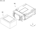
- the camera module 10 may include a first camera actuator 1000 and a second camera actuator 2000.
- the first camera actuator 1000 may be a zoom and/or auto focus actuator.
- the first camera actuator 1000 may include a plurality of lens groups.
- the first camera actuator 1000 may perform a zoom or auto focus function by moving at least one lens in an optical axis direction according to a control signal from a controller (not shown).
- the second camera actuator 2000 may be an Optical Image Stabilizer (OIS) actuator.
- OIS Optical Image Stabilizer
- light incident on the camera module 10 from the outside may be firstly incident on the second camera actuator 2000.
- the path of the light incident on the second camera actuator 2000 may be changed to be incident on the first camera actuator 1000.
- the light passing through the first camera actuator 1000 may be incident to an image sensor (not shown).
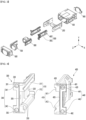
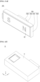
- FIG. 1 is a perspective view of a first camera actuator according to an embodiment
- FIG. 2 is a perspective view of the first camera actuator of FIG. 1 in which some components are omitted
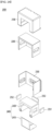
- FIG. 3 is an exploded perspective view of the first camera actuator shown in FIG. 1 .
- a first camera actuator 1000 may include a base 100, a driving part 200 disposed on the base 100, and a first lens assembly 600.
- FIG. 2 is a perspective view of the first camera actuator 1000 of FIG. 1 in which the base 100, the first lens assembly 600, and the fourth lens assembly 900 are omitted.
- the first camera actuator 1000 may include a rail guide part 500, a second lens assembly 700 and a third lens assembly 800.
- the rail guide part 500 may guide the movement of the second lens assembly 700 and the third lens assembly 800 in the base 100.
- the rail guide part 500 may include a first guide part 300 for guiding the movement of the second lens assembly 700 and a second guide part 400 for guiding the movement of the third lens assembly 800.
- the driving part 200 may include a circuit board 210, a first driving part 220 and a second driving part 230.
- the first driving part 220 may include a first driving coil and a first driving magnet.
- the second driving part 230 may include a second driving coil and a second driving magnet. The first driving coil and the first driving magnet of the first driving part 220 may provide a first driving force for moving the second lens assembly 700 along a rail of the first guide part 300 in the optical axis direction.
- the second driving coil and the second driving magnet of the second driving part 230 may provide a second driving force for moving the third lens assembly 800 along the rail of the second guide part 400 in the optical axis direction. driving force can be provided.
- each of the first driving part 220 and the second driving part 230 may further include a yoke (to be described later). This will be described in more detail below.
- the z-axis means the optical axis direction or a direction parallel thereto
- the xz plane means a ground
- the x-axis means a direction perpendicular to the z-axis in the ground (xz plane)
- the y-axis may mean a direction perpendicular to the ground.
- the first camera actuator 1000 may include a base 100, a driving part 200, a rail guide part 500, a first lens assembly 600, a second lens assembly 700, the third lens assembly 800 and the fourth lens assembly 900.
- the rail guide part 500 may include a first guide part 300 disposed on one side of the base 100 and a second guide part 400 disposed on the other side of the base 100.
- the first guide part 300 may correspond to the second lens assembly 700
- the second guide part 400 may correspond to the third lens assembly 800.
- a first rolling member (described later) may be disposed between the first guide part 300 and the second lens assembly 700.
- a second rolling member (described later) may be disposed between the second guide part 400 and the third lens assembly 800.
- the embodiment may include a plurality of lens assemblies.
- the first lens assembly 600, the second lens assembly 700, the third lens assembly 800, and the fourth lens assembly 900 may be sequentially disposed from one side.
- the first lens assembly 600 may be disposed farthest from an image sensor (not shown) or closest to the second camera actuator 2000.
- the fourth lens assembly 900 may be disposed closest to the image sensor (not shown) or farthest from the second camera actuator 2000.
- the second lens assembly 700 and the third lens assembly 800 may be disposed in the base 100 between the first lens assembly 600 and the fourth lens assembly 900.
- the first lens assembly 600 and the fourth lens assembly 900 may be a fixed part having fixed positions.
- an image sensor (not shown) may be disposed outside the fourth lens assembly 900.
- a second camera actuator 2000 may be disposed outside the first lens assembly 100.
- the second lens assembly 700 and the third lens assembly 800 may be a moving part whose positions are moved.
- the embodiment may include a rail guide part 500 for moving the second lens assembly 700 and the third lens assembly 800 in the optical axis direction.
- the rail guide part 500 includes a first guide part 300 disposed adjacent to a first sidewall 100a of the base 100 and a second guide part 400 disposed adjacent to the second sidewall 100b of the base 100.
- the first guide part 300 may be disposed between the second lens assembly 700 and the first sidewall 100a of the base 100.
- the second guide part 400 may be disposed between the third lens assembly 800 and the second sidewall 100b of the base 100.
- the first sidewall 100a and the second sidewall 100b of the base 100 may face each other.
- the first guide part 300 and the second guide part 400 may be disposed facing each other in the base 100.
- the second lens assembly 700 and the third lens assembly 800 may move (or drive) in a state where the first guide part 300 and the second guide part 400 precisely numerically controlled are coupled in the base 100. Accordingly, the embodiment can reduce the frictional torque and thus reduce the frictional resistance. Accordingly, the embodiment may achieve technical effects such as improvement of driving force during zooming, reduction of power consumption, and improvement of control characteristics.
- the embodiment allows the base 100 and the rail guide part 500 to be separately employed, and accordingly, it is possible to prevent a gradient from occurring.
- the base 100 may be injected in the Z-axis direction.
- the base and the rail guide part are integrally formed, there is a problem that a straight line of the rail is distorted due to the occurrence of a gradient as the rail is ejected in the Z-axis direction.
- the embodiment it is possible to prevent the occurrence of a gradient compared to the comparative example as the first guide part 300 and the second guide part 400 are injected separately from the base 100, thereby allowing precise injection.
- the first guide part 300 and the second guide part 400 are injected in the X-axis, and an injection length may be shorter than that of the base 100. Accordingly, the embodiment can prevent the problem of twisting of the rails respectively formed on the first guide part 300 and the second guide part 400.
- FIG. 4 is an enlarged perspective view of one side of a rail guide part according to an embodiment
- FIG. 5 is an enlarged view of a specific region of the rail guide part of FIG. 4
- FIG. 6 is an enlarged perspective view of the other side of a rail guide part.
- the rail guide part 500 includes a first guide part 300 and a second guide part 400.
- the first guide part 300 may include a single or a plurality of first rails 310.
- the second guide part 400 may include a single or a plurality of second rails 410.
- the first rail 310 of the first guide part 300 may include a first-first rail 311 and a first-second rail 312.
- the first guide part 300 may include a first supporting part 320 between the first-first rail 311 and the first-second rail 312.
- the second rail 410 of the second guide part 400 may include a second-first rail 411 and a second-second rail 412.
- the second guide part 400 may include a second supporting part 420 between the second-first rail 411 and the second-second rail 412.
- each of the first guide part 300 and the second guide part 400 includes a plurality of rails. Accordingly, each of the second lens assembly 700 and the third lens assembly 800 according to the embodiment may move along the plurality of rails in the optical axis direction.
- each guide part is provided with two rails, it is possible to secure the movement accuracy of the lens assembly with the other guide part even when distortion of one rail occurs.
- each guide part has two rails, so that even if an issue of frictional force of a rolling member (to be described later) occurs on one rail, the rolling drive proceeds smoothly on the other rail. Accordingly, the driving force can be secured.
- the first rail 310 may be connected from one surface (or one side) of the first guide part 300 to the other surface (or other side).
- the first rail 310 may be formed to extend in the optical axis direction from the first guide part 300.
- the second rail 410 may be connected from one surface (or one side) of the second guide part 400 to the other surface (or other side).
- the second rail 410 may be formed to extend in the optical axis direction from the second guide part 400.
- the camera actuator according to the embodiment and the camera module including the same may maintain an alignment state and distance between a plurality of lens groups by solving the problem of lens decentering or tilting during zooming, and it can solve reliability problems such as angle of view change or out of focus.
- the first guide part 300 includes a first-first rail 311 and a first-second rail 312, and accordingly alignment accuracy can be improved by guiding the movement of the second lens assembly 700 by the first-first rail 311 and the first-second rail 312.
- the second guide part 400 includes a second-first rail 411 and a second-second rail 412, and accordingly alignment accuracy can be improved by guiding the movement of the third lens assembly 800 by the second-first rail 411 and the second-second rail 412.
- each guide part has two rails, it is possible to maximize a distance of the rolling member to be described later. Accordingly, the embodiment can prevent magnetic field interference while improving the driving force for the movement of the second lens assembly 700 and the third lens assembly 800, thereby preventing the tilt of the lens assembly in a stationary or moving state.
- the first guide part 300 may include a first guide protrusion 330 extending in a lateral direction perpendicular to an extending direction of the first rail 310.
- the first rail 310 may extend in the z-axis direction
- the first guide protrusion 330 may extend in the x-axis direction from one side of the first rail 310.
- a first coupling hole 340 may be formed on the first guide protrusion 300.
- a plurality of first coupling holes 340 may be formed on the first guide protrusion 300.
- the first coupling hole 340 may include a first-first coupling hole 341 and a first-second coupling hole 342 spaced apart in the y-axis direction on the first guide protrusion 300.
- the first-first coupling hole 341 and the first-second coupling hole 342 may have different shapes.
- the first-first coupling hole 341 may be formed in a circular shape
- the first-second coupling hole 342 may be formed in an elliptical shape.
- the second guide part 400 may include a second guide protrusion 430 extending in a lateral direction perpendicular to an extending direction of the second rail 410.
- the second rail 410 may extend in the z-axis direction
- the second guide protrusion 430 may extend in the x-axis direction from one side of the second rail 510.
- a second coupling hole 440 may be formed on the second guide protrusion 400.
- a plurality of second coupling holes 440 may be formed on the second guide protrusion 400.
- the second coupling hole 440 may include a second-first coupling hole 441 and a second-second coupling hole 442 spaced apart in the y-axis direction on the second guide protrusion 400.
- the second-first coupling hole 441 and the second-second coupling hole 442 may have different shapes.
- the second-first coupling hole 441 may be formed in an elliptical shape
- the second-second coupling hole 442 may be formed in a circular shape.
- coupling holes adjacent to each other in the first coupling hole 340 and the second coupling hole 440 may have different shapes.
- the first-first coupling hole 341 of the first coupling hole 340 may have a circular shape
- the second-first coupling hole 441 of the second coupling hole 440 adjacent thereto may have an elliptical shape.
- the first-second coupling hole 342 of the first coupling hole 340 may have an elliptical shape
- the second-second coupling hole 442 of the second coupling hole 440 adjacent thereto may have a circular shape.
- coupling holes positioned in a diagonal direction from each other in the first coupling hole 340 and the second coupling hole 440 may have the same shape as each other.
- the first-first coupling hole 341 of the first coupling hole 340 may be circular
- the second-second coupling hole 442 of the second coupling hole 440 located in a diagonal direction of the first-first coupling hole may be circular.
- the first-second coupling hole 342 of the first coupling hole 340 may have an elliptical shape
- the second-first coupling hole 441 of the second coupling hole 440 positioned in a diagonal direction of first-second coupling hole may have an elliptical shape.
- a coupling hole having a circular shape may be referred to as a regular-hole
- a coupling hole having an elliptical shape may be referred to as a long-hole.
- the first-first coupling hole 341 and the second-second coupling hole 442 When the first guide part 300/second guide part 400 and the base 100 are coupled, the first-first coupling hole 341 and the second-second coupling hole 442, the first-first coupling hole 341 and the second-second coupling hole 442, which are a regular hole with a circular shape, can firmly couple the first guide part 300 to the base 100.
- the first-second coupling hole 342 and the second-first coupling hole 441 which are a lone hole with an elliptical shape, can prevent rotation in the x-axis direction while covering fine assembly tolerances occurring in the y-axis direction.
- first-second coupling hole 342 and the second-first coupling hole 441 which are a lone hole with an elliptical shape, may have a shape extending along the y-axis compared to the first-first coupling hole 341 and the second-second coupling hole 442.
- diameters of the first-second coupling hole 342 and the second-first coupling hole 441 in the x-axis direction may be the same as diameters of the first-first coupling hole 341 and the second-second coupling hole 442 in the x-axis direction.
- diameters of the first-second coupling hole 342 and the second-first coupling hole 441 in the y-axis direction may be greater than diameters of the first-first coupling hole 341 and the second-second coupling hole 442 in the y-axis direction.
- the first guide part 300 may include a plurality of recesses for designating a flow path of an adhesive member (not shown).
- the second guide part 400 may include a plurality of recesses for designating a flow path of an adhesive member (not shown).
- the adhesive member may be a bonding member applied when the first guide part 300/second guide part 400 and the base 100 are coupled.
- the first guide part 300 may include a first-first recess 391 formed around the first-first coupling hole 341.
- the first-first recess 391 may have a shape corresponding to the first-first coupling hole 341.
- a size of the first-first recess 391 may be greater than a size of the first-first coupling hole 341.
- a width of the first-first recess 391 in the x-axis direction may be greater than a width of the first-first coupling hole 341 in the x-axis direction.
- a width of the first-first recess 391 in the y-direction may be greater than a width of the first-first coupling hole 341 in the y-direction.
- the first-first coupling hole 341 may be formed in the first-first recess 391.
- the first-first recess 391 may designate a flow path of an adhesive member (not shown) applied around the first-first coupling hole 341.
- the first-first recess 391 may function as a dam to prevent overflow of an adhesive member (not shown) applied around the first-first coupling hole 341.
- an overflow of the adhesive member (not shown) may occur in a process of coupling the first lens assembly 600 on the first guide part 300, and accordingly, the adhesive member (not shown) may move toward the first rail 310 of the first guide part 300.
- a first-first recess 391 in the embodiment is formed around the first-first coupling hole 341 to prevent the adhesive member (not shown) from overflowing.
- the first guide part 300 of the embodiment may include a first-second recess 392 formed around the first-second coupling hole 342.
- the first-second recess 392 may have a shape corresponding to the first-second coupling hole 342.
- a size of the first-second recess 392 may be greater than a size of the first-second coupling hole 342.
- a width of the first-second recess 392 in the x-axis direction may be greater than a width of the first-second coupling hole 342 in the x-axis direction.
- a width of the first-second recess 392 in the y-direction may be greater than a width of the first-second coupling hole 342 in the y-direction.
- the first-second coupling hole 342 may be formed in the first-second recess 392.
- the first-second recess 392 may designate a flow path of an adhesive member (not shown) applied around the first-second coupling hole 342.
- the first-second recess 392 may function as a dam to prevent overflow of an adhesive member (not shown) applied around the first-second coupling hole 342.
- the first guide part 300 of the embodiment may include a first-third recess 393.
- the first-third recess 393 may have a shape extending in the y-axis direction from the first guide part 300.
- the first-third recess 393 may be formed between the first coupling hole 340 and the first rail 310.
- the first-third recess 393 may be formed to elongate in the y-axis direction between the first coupling hole 340 and the first rail 310.
- the first-third recess 393 may additionally block overflow of an adhesive member (not shown) from the first-first recess 391 or the first-second recess 392.
- the inner side (specifically, the first rail) of the first guide part 300 may be a part that plays the most important role in operation reliability of the first camera actuator 1000.
- overflow of the adhesive member (not shown) may occur even in a state where the first-first recess 391 and the first-second recess 392 are formed.
- the embodiment may further block the flow of the adhesive member (not shown) to the inside of the first guide part 300, specifically to the first rail 310.
- the first guide part 300 of the embodiment forms a recess around the first coupling hole 340 to primarily block the overflow of an adhesive member (not shown), and forms a recess between the first coupling hole 340 and the first rail 310 to secondarily block the overflow of an adhesive member (not shown). Accordingly, the embodiment can fundamentally block the flow of the adhesive member (not shown) toward the inside of the first guide part 300 (or toward the first rail), thereby improving operation reliability.
- the second guide part 400 may include a second-first recess 491 formed around the second-first coupling hole 441.
- the second-first recess 491 may have a shape corresponding to the second-first coupling hole 441.
- a size of the second-first recess 491 may be greater than a size of the second-first coupling hole 441.
- a width of the second-first recess 491 in the x-axis direction may be greater than a width of the second-first coupling hole 441 in the x-axis direction.
- a width of the second-first recess 491 in the y-direction may be greater than a width of the second-first coupling hole 441 in the y-direction.
- the second-first coupling hole 441 may be formed in the second-first recess 491.
- the second-first recess 491 may designate a flow path of an adhesive member (not shown) applied around the second-first coupling hole 441.
- the second-first recess 491 may function as a dam to prevent overflow of an adhesive member (not shown) applied around the second-first coupling hole 441.
- an overflow of the adhesive member (not shown) may occur in a process of coupling the first lens assembly 600 on the second guide part 400, and accordingly, the adhesive member (not shown) may move toward the second rail 410 of the second guide part 400.
- a second-first recess 491 in the embodiment is formed around the second-first coupling hole 441 to prevent the adhesive member (not shown) from overflowing.
- the second guide part 400 of the embodiment may include a second-second recess 492 formed around the second-second coupling hole 442.
- the second-second recess 492 may have a shape corresponding to the second-second coupling hole 442.
- a size of the second-second recess 492 may be greater than a size of the second-second coupling hole 442.
- a width of the second-second recess 492 in the x-axis direction may be greater than a width of the second-second coupling hole 442 in the x-axis direction.
- a width of the second-second recess 492 in the y-direction may be greater than a width of the second-second coupling hole 442 in the y-direction.
- the second-second coupling hole 442 may be formed in the second-second recess 492.
- the second-second recess 492 may designate a flow path of an adhesive member (not shown) applied around the second-second coupling hole 442.
- the second-second recess 492 may function as a dam to prevent overflow of an adhesive member (not shown) applied around the second-second coupling hole 442.
- the second guide part 400 of the embodiment may include a second-third recess 493.
- the second-third recess 493 may have a shape extending in the y-axis direction from the second guide part 400.
- the second-third recess 493 may be formed between the second coupling hole 440 and the second rail 410.
- the second-third recess 493 may be formed to elongate in the y-axis direction between the second coupling hole 440 and the second rail 410.
- the second-third recess 493 may additionally block overflow of an adhesive member (not shown) from the second-first recess 491 or the second-second recess 492.
- the inner side (specifically, the second rail) of the second guide part 400 may be a part that plays the most important role in operation reliability of the first camera actuator 1000.
- overflow of the adhesive member (not shown) may occur even in a state where the second-first recess 491 and the second-second recess 492 are formed.
- the embodiment may further block the flow of the adhesive member (not shown) to the inside of the second guide part 400, specifically to the second rail 410.
- the second guide part 400 of the embodiment forms a recess around the second coupling hole 440 to primarily block the overflow of an adhesive member (not shown), and forms a recess between the second coupling hole 440 and the second rail 410 to secondarily block the overflow of an adhesive member (not shown). Accordingly, the embodiment can fundamentally block the flow of the adhesive member (not shown) toward the inside of the second guide part 400 (or toward the second rail), thereby improving operation reliability.
- the first rail 310 of the first guide part 300 may include a plurality of rails having different shapes. That is, as described above, the first rail 310 may include a first-first rail 311 and a first-second rail 312.
- first-first rail 311 may have a first shape.
- first-second rail 312 may have a second shape different from the first shape.
- the second rail 410 of the second guide part 400 may include a plurality of rails having different shapes. That is, as described above, the second rail 410 may include a second-first rail 411 and a second-second rail 412.
- the second-first rail 411 may have a second shape.
- the second-second rail 412 may have a first shape different from the second shape.
- first shape of the first-first rail 311 may be a 'V' shape.
- first shape of the second-second rail 412 may be a 'V' shape.
- second shape of the first-second rail 312 and the second shape of the second-second rail 412 may be 'L' shapes.
- first shape and the second shape may have different shapes other than the 'V' and 'L' shapes.
- the rails having the same shape as each other in the first rail 310 and the second rail 410 may be positioned in a diagonal direction.
- the first-first rail 311 of the first rail 310 having the first shape and the second-second rail 412 of the second rail 410 may be positioned in a diagonal direction.
- the first-second rail 312 of the first rail 310 having the second shape and the second-first rail 411 of the second rail 410 may be positioned in a diagonal direction.
- first ribs 350 may be formed inside the first supporting part 320 of the first guide part 300.
- a first rib 350 may be formed between the first-first rail 311 and the second rail 312 of the first guide part 300.
- the first rib 350 may improve the accuracy of dimensional management of the first-first rail 311 and the second rail 312.
- shrinkage occurs as the amount of injection molding increases or the thickness of injection molding increases, which makes it difficult to manage dimensions, and when the amount of injection molding is reduced, there is a problem in that the strength is weakened.
- the first rib 350 is provided inside the first supporting part 320, and it is possible to secure strength while reducing the amount of injection molding and increasing the accuracy of dimension management.
- a single or a plurality of second ribs may be formed inside the second supporting part 420 of the second guide part 400.
- the second guide part 400 may include a rail part recess 470 and a supporting part recess 480.
- a second rail 410 is formed inside the second guide part 400.
- a rail part recess 470 may be formed on an outer side opposite to the second rail 410 of the second guide part 400.
- a supporting part recess 480 may be formed outside the second supporting part 420 of the second guide part 400. The rail part recess 470 and the supporting part recess 480 prevents shrinkage by reducing the injection amount of the second guide part 400, and it is possible to secure strength while increasing the accuracy of dimension management.
- a rail part recess (not shown) and a supporting part recess (not shown) of the first guide part may also be formed outside the first guide part 300 corresponding to the second guide part 400.
- the first guide part 300 may include a first guide protrusion 360 formed in a region opposite to the first coupling hole 340.
- the first guide part 300 may include a first-first guide protrusion 361 formed in a region opposite to the first-first coupling hole 341 and a first-second guide protrusion 362 formed in a region opposite to the first-second coupling hole 342.
- the first guide protrusion 361 and the second guide protrusion 362 may be fitted into a coupling recess of a third sidewall 100c of the base 100 to be described later.
- the second guide part 400 may include a second guide protrusion 460 formed in a region opposite to the second coupling hole 440.
- the second guide part 400 may include a second-first guide protrusion 461 formed in a region opposite to the second-first coupling hole 441 and a second-second guide protrusion 462 formed in a region opposite to the second-second coupling hole 442.
- the second-first guide protrusion 461 and the second-second guide protrusion 462 may be fitted into a coupling recess of the third sidewall 100c of the base 100 to be described later.
- the second lens assembly 700 the third lens assembly 800, the first rolling member, and the second rolling member will be described in detail.
- FIG. 7 is a perspective view of the second lens assembly shown in FIG. 3
- FIG. 8 is a perspective view of the second lens assembly shown in FIG. 7 in which some components are omitted
- FIG. 9 is a perspective view of the third lens assembly shown in FIG. 3
- FIG. 10 is a perspective view of the third lens assembly shown in FIG. 9 in which some components are omitted.
- the embodiment may include a second lens assembly 700 moving along the first guide part 300 and a third lens assembly 800 moving along the second guide part 400.
- the second lens assembly 700 may include a second lens barrel 710 on which a second lens group 730 is disposed, and a first driving part housing 720 in which a part of the driving part 200 (specifically, the first magnet and the first yoke of the first driving part) is disposed.
- the second lens barrel 710 and the first driving part housing 720 may be a first housing.
- the first housing may have a barrel or barrel shape.
- the first driving part housing 720 may be a first magnet/yoke disposition part in which a first magnet 222 and a first yoke 223 of the first driving part 220 constituting the driving part 200 are disposed.
- the third lens assembly 800 includes a third lens barrel 810 on which a third lens group 830 is disposed, and a second driving part housing 820 in which a part of the driving part 200 (specifically, the second magnet and the second yoke of the second driving part) is disposed.
- the third lens barrel 810 and the second driving part housing 820 may be the second housing.
- the second housing may have a barrel or barrel shape.
- the second driving part housing 820 may be a second magnet/yoke disposition part in which the second magnet 232 and the second yoke 233 of the second driving part 230 constituting the driving part 200are disposed.
- the second lens assembly 700 corresponds to the two first rails 310 of the first guide part 300
- the third lens assembly 800 corresponds to the two second rails 410 of the second guide part 400.
- An embodiment may include a first rolling member 740 and a second rolling member 840.
- the first rolling member 740 may include a single ball or a plurality of balls.
- the second rolling member 840 may include a single ball or a plurality of balls.
- the embodiment may include a first rolling member 740 disposed between the second lens assembly 700 and the first guide part 300. Also, the embodiment may include a second rolling member 840 disposed between the third lens assembly 800 and the second guide part 400.
- the first rolling member 740 may includes a single or a plurality of first balls 741 disposed on an upper side of the first driving part housing 720 and a single or a plurality of second balls 742 disposed on a lower side of the first driving part housing 720.
- the first ball 741 may move along a first-first rail 311, which is one of the first rails 310 of the first guide part 300.
- the second ball 742 may move along the first-second rail 312, which is another one of the first rails 310 of the first guide part 300.
- the first ball 741 corresponds to the first-first rail 311 and may include a first-first ball 741a and a first-second ball 741b spaced apart from each other by a predetermined distance.
- the second ball 742 corresponds to the first-second rail 312 and may include a second-first ball 742a and a second-second ball 742b spaced apart from each other by a predetermined distance.
- the second rolling member 840 may includes a single or a plurality of third balls 841 disposed on an upper side of the second driving part housing 820 and a single or plurality of fourth balls 842 disposed on a lower side of the second driving part housing 820.
- the third ball 841 may move along a second-first rail 411, which is one of the second rails 410 of the second guide part 400.
- the fourth ball 842 may move along the second-second rail 412, which is another one of the second rails 410 of the second guide part 400.
- the third ball 841 corresponds to the second-first rail 411 and may include a third-first ball 841a and a third-second ball 841b spaced apart from each other by a predetermined distance.
- the fourth ball 842 may include a fourth-first ball 842a and a fourth-second ball 842b that correspond to the second-second rail 412 and are spaced apart from each other by a predetermined distance.
- the camera actuator according to the embodiment and the camera module including the same may maintain an alignment state and distance between a plurality of lens groups by solving the problem of lens decentering or tilting during zooming, and it is possible to improve image quality by solving problems such as change in angle of view or out of focus.
- the first guide part 300 includes a first-first rail and a first-second rail, and the first-first rail and the first-second rail guide the movement of the second lens assembly 700. Accordingly, when the second lens assembly 700 moves, it can improve the accuracy of optical axis alignment with the third lens assembly 800.
- the second lens assembly 700 may include a first ball recess 750 in which a first rolling member 740 is disposed.
- the third lens assembly 800 may include a second ball recess 850 in which the second rolling member 840 is disposed.
- the number of the first ball recess 750 and the second ball recess 850 may be plural.
- the number of first ball recesses 750 may correspond to the number of balls constituting the first rolling member 740.
- the number of second ball recesses 850 may correspond to the number of balls constituting the second rolling member 840.
- the first ball recess 750 may include four recesses spaced apart from each other to correspond to the first rolling member 740.
- the second ball recess 850 may include four recesses spaced apart from each other to correspond to the second rolling member 840.
- a distance between two recesses among four recesses constituting the first ball recess 750 may be greater than the thickness of the second lens barrel 710 based on the optical axis direction.
- a distance between two recesses among four recesses constituting the second ball recess 850 may be greater than a thickness of the third lens barrel 810 based on the optical axis direction.
- the first ball recess 750 of the second lens assembly 700 may have a V shape.
- the second ball recess 850 of the third lens assembly 800 may have a V shape.
- the first ball recess 750 and the second ball recess 850 may have a U-shape or a shape in contact with the ball at two or three points.
- a first driving part disposition recess 770 may be formed in a region between the first ball recess 750 in the second lens assembly 700.
- a second driving part disposition recess 870 may be formed in a region between the second ball recesses 850 in the third lens assembly 800.
- FIG. 11 is a cross-sectional view in a x-axis direction of the camera module according to the embodiment shown in FIG. 2 .
- a first guide part 300 and a second guide part 400 may be respectively inserted and disposed in the base 100, and the second lens assembly 700 may be disposed to correspond to the first guide part 300, and the third lens assembly 800 may be disposed to correspond to the second guide part 400.
- a first rolling member 740 may be inserted between the first rail 310 of the first guide part 300 and the second lens assembly 700.
- a second rolling member 840 may be inserted between the second rail 410 of the second guide part 400 and the third lens assembly 800.
- the second lens assembly 700 may move along the first rail 310 of the first guide part 300 in the optical axis direction through the first rolling member 740.
- the third lens assembly 800 may move along the second rail 410 of the second guide part 400 in the optical axis direction through the second rolling member 840.
- the embodiment has an effect of preventing the second lens assembly 700 and the second lens assembly 700 from being reversely inserted into the base 100.
- the embodiment may solve a problem of mis-insertion in which the third lens assembly 800 is disposed where the second lens assembly 700 is to be disposed and a problem of mis-insertion in which the second lens assembly 700 is disposed where the third lens assembly 800 is to be disposed.
- upper and lower widths of the second lens assembly 700 may have a first width A10.
- upper and lower widths of the third lens assembly 800 may have a second width B10 different from the first width A10. Accordingly, the embodiment may allow the third lens assembly 800 not to be inserted in a region where the second lens assembly 700 is to be disposed by the dimension design of the second lens assembly 700 and the third lens assembly 800 as described above, thereby improving reliability.
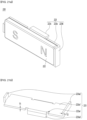
- FIG. 12 is an exemplary view of driving a second lens assembly according to an embodiment.
- a magnetization method of the first magnet 222 of the first camera actuator 1000 may be a perpendicular magnetization method.
- both the N pole 222N and the S pole 222S of the first magnet 222 may be magnetized to face the first coil 221.
- the N pole 222N and the S pole 222S of the first magnet 222 may be respectively disposed to correspond to a region in which a current flows in a y-axis direction perpendicular to the ground in the first coil 221.
- a magnetic force DM is applied in an opposite direction to the x-axis from the N pole 222N of the first magnet 222 (a direction of the magnetic force may be a positive or negative direction of the illustrated direction), when a current DE flows in the y-axis direction in a region of the first coil 221 corresponding to the N pole 222N, the electromagnetic force DEM acts in the z-axis direction according to Fleming's left-hand rule.
- a magnetic force DM is applied in the x-axis direction from the S pole 222S of the first magnet 222, when a current DE flows in the opposite direction of the y-axis perpendicular to the ground in the first coil 221 corresponding to the S pole 222S, the electromagnetic force DEM acts in the z-axis direction according to Fleming's left-hand rule (The direction of the electromagnetic force may be positive or negative of the illustrated direction).
- the first coil 221 of the first driving part 220 is in a fixed state
- the second lens assembly 700 which is a mover in which the first magnet 222 of the first driving part 220 is disposed, may move back and forth along the first rail 310 of the first guide part 300 in a direction parallel to the z-axis direction by the electromagnetic force (DEM) according to a current direction.
- the electromagnetic force DEM may be controlled in proportion to the current DE applied to the first coil 221.
- an electromagnetic force is generated between the second coil 231 and the second magnet 232 of the second driving part 230 in the camera module according to the embodiment, so that the third lens assembly 800 on which the second magnet 232 is disposed may move along the second rail 410 of the second guide part 400 in a direction parallel to the optical axis.
- FIG. 13 is a perspective view of a first lens assembly according to an embodiment
- FIG. 14 is a perspective view of the first lens assembly of FIG. 13 in which a first lens group is omitted.
- a first lens assembly 600 may include a first lens barrel 610 and a first lens group 620.
- the third lens assembly 800 may have a barrel part recess 611r formed on the first lens barrel 610.
- the barrel part recess 611r can uniformly adjust a thickness of the first lens barrel 610 of the first lens assembly 600 and increase the accuracy of numerical control by reducing the amount of the injected material.
- the first lens barrel 610 may include a plurality of ribs 630.
- the plurality of ribs 630 may improve the strength of the first lens barrel 610.
- the plurality of ribs 630 may be a stopper coupling part to which a stopper (not shown) is coupled.
- stoppers (not shown) may be coupled to each of the plurality of ribs 630.
- the stopper (not shown) may be disposed between the first lens assembly 600 and the second lens assembly 700 to limit the movement of the second lens assembly 700. For example, when the second lens assembly 700 moves in a direction in which the first lens assembly 600 is disposed, the movement of the second lens assembly 700 may be restricted by the stopper.
- the third lens barrel 610 may include a lens insertion part 612h into which the third lens group 620 is inserted.
- the lens insertion part 612h may have a hole shape passing through the third lens barrel 610 in an optical axis direction.
- the third lens assembly 800 may include a plurality of coupling holes.
- the first lens assembly 600 may include a third coupling hole 640 and a fourth coupling hole 650.
- the third coupling hole 640 may correspond to the first coupling hole 340 of the first guide part 300.
- the third coupling hole 640 may include a third-first coupling hole 641 and a third-second coupling hole 642 spaced apart in the y-axis direction on one side of the third lens barrel 810 of the third lens assembly 800.
- the third-first coupling hole 641 and the third-second coupling hole 642 may have different shapes.
- the third-first coupling hole 641 may be formed in a circular shape
- the third-second coupling hole 642 may be formed in an elliptical shape.
- the third coupling hole 640 may be aligned with the first coupling hole 340 in an optical axis direction.
- a center of the third coupling hole 640 may be aligned with a center of the first coupling hole 340 in the optical axis direction.
- a protrusion of the base 100 described later may be inserted into the third coupling hole 640.
- the fourth coupling hole 650 may correspond to the second coupling hole 440 of the second guide part 400.
- the fourth coupling hole 6500 includes a fourth-first coupling hole 651 and a fourth-second coupling hole 652 spaced apart in the y-axis direction on the other side of the third lens barrel 810 of the third lens assembly 800.
- the fourth-first coupling hole 651 and the fourth-second coupling hole 652 may have different shapes.
- the fourth-first coupling hole 651 may be formed in an elliptical shape
- the fourth-second coupling hole 652 may be formed in a circular shape.
- coupling holes adjacent to each other in the x-axis direction in the third coupling hole 640 and the fourth coupling hole 650 may have different shapes.
- the third-first coupling hole 641 of the third coupling hole 640 has a circular shape
- the fourth-first coupling hole 651 of the fourth coupling hole 650 adjacent to third-first coupling hole in the x-axis direction has an elliptical shape.
- the third-second coupling hole 642 of the third coupling hole 640 has an elliptical shape
- the fourth-second coupling hole 652 of the fourth coupling holes 650 adjacent to the third-second coupling hole in the x-axis direction may have a circular shape.
- coupling holes positioned in a diagonal direction in the third coupling hole 640 and the fourth coupling hole 650 may have the same shape.
- the third-first coupling hole 641 of the third coupling hole 640 may have a circular shape
- the fourth-second coupling hole 652 of the fourth coupling hole 650 positioned in a diagonal direction with the third-first coupling hole may have a circular shape.
- the third-second coupling hole 642 of the third coupling hole 640 may have an elliptical shape
- the fourth-first coupling hole 651 of the fourth coupling hole 650 located in a diagonal direction with the third-second coupling hole may have an elliptical shape.
- a coupling hole having a circular shape may be referred to as a regular hole
- a coupling hole having an elliptical shape may be referred to as a long hole.
- the third-first coupling hole 641 and the fourth-second coupling hole 652 which are a regular hole with a circular shape, may firmly couple the first lens assembly 600 to the base 100.
- the third-second coupling hole 642 and the fourth-first coupling hole 651 which are a lone hole with an elliptical shape, can prevent rotation in the x-axis direction while covering fine assembly tolerances occurring in the y-axis direction.
- the third-second coupling hole 642 and the fourth-first coupling hole 651 which are a lone hole with an elliptical shape, may have a shape extending along the y-axis compared to the third-first coupling hole 641 and the fourth-second coupling hole 652.
- diameters of the third-second coupling hole 642 and the fourth-first coupling hole 651 in the x-axis direction may be a same as diameters of the third-first coupling hole 641 and the fourth-second coupling hole 652 in the x-axis direction.
- diameters of the third-second coupling hole 642 and the fourth-first coupling hole 651 in the y-axis direction may be greater than diameters of the third-first coupling hole 641 and the fourth-second coupling hole 652 in the y-axis direction.
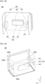
- FIG. 15 is a perspective view of a base in a first camera actuator according to an embodiment
- FIG. 16 is a front view of the base shown in FIG. 15
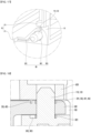
- FIG. 17 is an enlarged view of a region where coupling protrusion of a base is formed
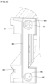
- FIG. 18 is a cross-sectional view of a base, a rail guide part, and a first lens assembly in a coupled state according to an embodiment.
- a first guide part 300, a second guide part 400, a second lens assembly 700 and a third lens assembly 800 may be accommodated in the base 100.
- the first lens assembly 600 may be disposed spaced apart from the second lens assembly 700 on one side surface of the base 100.
- the fourth lens assembly 900 may be disposed spaced apart from the third lens assembly 800 on the other side surface of the base 100.
- the base 100 may include a plurality of side walls.
- the base 100 may include a first sidewall 100a, a second sidewall 100b, a third sidewall 100c, and a fourth sidewall 100d.
- the base 100 may include an upper part 100e and a lower part 100f together with the plurality of side wall.
- the base 100 may include a first sidewall 100a and a second sidewall 100b corresponding to the first sidewall 100a.
- the second sidewall 100b may be disposed in a direction facing the first sidewall 100a.
- the first sidewall 100a and the second sidewall 100b may include a first opening OA1 and a second opening OA2, respectively.
- the first opening OA1 may be an insertion space into which a part of the driving part 200 disposed outside the first sidewall 100a of the base 100 is inserted.
- the circuit board 210 of the driving part 200 is disposed outside the first sidewall 100a.
- the first coil 221 of the first driving part 220 may be disposed on the circuit board 210.
- the first coil 221 of the first driving part 220 may be disposed inside the base 100 through the first opening OA1 formed in the first sidewall 100a in a state where the circuit board 210 is disposed outside the first sidewall 100a of the base 100.
- the second opening OA2 may be an insertion space into which a part of the second driving part 230 disposed outside the second sidewall 100b of the base 100 is inserted.
- the circuit board 210 of the driving part 200 is disposed outside the second sidewall 100b.
- the second coil 231 of the second driving part 230 may be disposed inside the base 100 through the second opening OA2 formed in the second sidewall 100b in a state where the circuit board 210 is disposed outside the second sidewall 100b of the base 100.
- the base 100 may include a third sidewall 100c disposed between the first sidewall 100a and the second sidewall 100b and connecting the first sidewall 100a and the second sidewall 100b.
- the third sidewall 100c may be disposed in a direction perpendicular to the first sidewall 100a and the second sidewall 100b.
- the first sidewall 100a, the second sidewall 100b, and the third sidewall 100c may be integrally injected or separately injected.
- a coupling protrusion may be formed on the fourth sidewall 100d of the base 100.
- a first coupling protrusion 110 and a second coupling protrusion 120 may be formed on the fourth sidewall 100d of the base 100.
- the first coupling protrusion 110 may be a protrusion to which the first guide part 300 is coupled.
- the first coupling protrusion 110 may correspond to the first coupling hole 340 of the first guide part 300.
- the first coupling protrusion 110 may include a first-first coupling protrusion 111 corresponding to the first-first coupling hole 341 of the first guide part 300 and a first-second coupling protrusion 112 corresponding to the first-second coupling hole 342 of the first guide part 300.
- the first coupling protrusion 110 may be a protrusion to which the first lens assembly 600 is coupled.
- the first coupling protrusion 110 may correspond to the third coupling hole 640 of the first lens assembly 600.
- the second coupling protrusion 120 may be a protrusion to which the second guide part 400 is coupled.
- the second coupling protrusion 120 may correspond to the second coupling hole 440 of the second guide part 400.
- the second coupling protrusion 120 may include a second-first coupling protrusion 121 corresponding to the second-first coupling hole 441 of the second guide part 400 and a second-second coupling protrusion 122 corresponding to the second-second coupling hole 442 of the second guide part 400.
- the second coupling protrusion 120 may be a protrusion to which the first lens assembly 600 is coupled.
- the second coupling protrusion 120 may correspond to the fourth coupling hole 650 of the first lens assembly 600.
- the base 100 may include a base recess BR formed around the first coupling protrusion 110 and the second coupling protrusion 120.
- the base recess BR may be a recess designating a flow path of an adhesive member (not shown).
- the adhesive member (not shown) may be a bonding member applied around the first coupling protrusion 110 and the second coupling protrusion 120.
- the embodiment may include a first base recess 111r formed around the first-first coupling protrusion 111.
- the first base recess 111r may include a first portion having a shape corresponding to the first-first coupling protrusion 111 and a second portion extending from the first portion.
- the first portion and the second portion of the first base recess 111r may be connected to each other. The first portion and the second portion will be described in more detail below.
- the base recess BR may include a second base recess 112r formed around the first-second coupling protrusion 112.
- the second base recess 112r may include a first portion having a shape corresponding to the first-second coupling protrusion 112 and a second portion connected to the first portion and extending from the first portion.
- the base recess BR may include a third base recess 121r formed around the second-first coupling protrusion 121.
- the third base recess 121r may include a first portion having a shape corresponding to the second-first coupling protrusion 121 and a second portion connected to the first portion and extending from the first portion.
- the base recess BR may include a fourth base recess 122r formed around the second-second coupling protrusion 122.
- the fourth base recess 122r may include a first portion having a shape corresponding to the second-second coupling protrusion 122 and a second portion connected to the first portion and extending from the first portion.
- the fourth sidewall 100d of the base 100 may include a first region R1 in which the first coupling protrusion 110 and the second coupling protrusion 120 are provided, and a second region R2 other than the first region R1.
- the first region R1 and the second region R2 may have different heights or thicknesses.
- the second region R2 may include a first protruding region P1 and a second protruding region P2 protruding in an optical axis direction based on the first region R1. That is, a first protruding region P1 and a second protruding region P2 may be formed in a region adjacent to the first region R1 where the coupling protrusions 110 and 120 are formed.
- the first region R1 and the second region R2 may be referred to as a stepped region.
- the base recess BR includes a first portion BR1 formed around the coupling protrusions 110 and 120.
- the first portion BR1 may have a shape corresponding to the coupling protrusions 110 and 120.
- the base recess BR may function as a dam of the adhesive member (not shown) even when only the first portion BR1 is included.
- the base 100 includes only the first portion BR1, it may be difficult to completely block an adhesive member (not shown) penetrating into an accommodation space inside the base 100.
- the embodiment includes an extension portion extending from the first portion BR1.
- the base recess BR may include a second-first portion BR2 extending from the first portion BR1 and contacting the first protruding region P1.
- the base recess BR may include a second-second portion BR3 extending from the first portion BR1 and contacting the second protruding region P2.
- the second-first portion BR2 and the second-second portion BR3 provide a flow path for an adhesive member (not shown) applied to the first portion BR1, and accordingly, it is possible to solve the problem that the adhesive member (not shown) overflows into the base 100.
- a coupling recess may be formed on an inner surface of the third sidewall 100c of the base 100.
- the coupling recess may include a first coupling recess 130 corresponding to the first guide part 300 and a second coupling recess 140 corresponding to the second guide part 400.
- a first coupling recess 130 may be provided on the inner surface of the third sidewall 100c of the base 100 so that the first guide protrusion 360 of the first guide part 300 is fitted.
- the first coupling recess 130 may include a first-first coupling recess 131 corresponding to the first-first guide protrusion 361 of the first guide part 300 and a first-second coupling recess 132 corresponding to the first-second guide protrusion 362.
- a second coupling recess may be provided on the inner surface of the third sidewall 100c of the base 100 so that the second guide protrusion 460 of the second guide part 300 is fitted.
- the second coupling recess 140 may include a second-first coupling recess 141 into which the second-first guide protrusion 461 of the second guide part 400 is fitted and coupled and a second-second coupling recess 142 into which the second-second guide protrusion 462 is fitted.
- the base 100 may include a third opening OA3.
- a third opening OA3 may be formed in the lower part 100f of the base 100.
- the third opening OA3 may be an insertion part into which a part of the driving part 200 is inserted.
- the driving part 200 includes a driver IC 240 disposed on a circuit board 210.
- the third opening OA3 formed in the lower part 100f of the base 100 may correspond to the driver IC.
- the circuit board 210 of the driving part 200 is disposed on the outer surface of the base 100.
- the driver IC 240 disposed on the circuit board 210 may be disposed within the inner accommodation space of the base 100 through the third opening OA3.
- FIGS. 19A, 19B , 20A and 20B are perspective views illustrating a driving part according to an embodiment
- FIG. 21A is a perspective view of a part of a first driving part shown in FIG. 19
- FIG. 21B is a detailed perspective view of a first yoke of a first driving part according to an embodiment
- FIG. 21C is a bottom perspective view of a first yoke of the embodiment
- FIG. 21D is a perspective view of some components of a first driving part according to a first additional embodiment
- FIG. 21E is a perspective view of some components of a first driving part according to a second additional embodiment.
- the driving part 200 may include a circuit board 210, a first driving part 220 and a second driving part 230.
- the first driving part 220 may include a coil, a magnet, and a yoke.
- the second driving part 230 may include a coil, a magnet, and a yoke.
- each of the first and second driving parts 220 and 230 may include a position sensor for sensing a position of the magnet and the position of the second lens assembly 700 or the third lens assembly 800.
- the circuit board 210 may be disposed surrounding an outer surface of the base 100.
- the circuit board 210 may be disposed surrounding the first sidewall 100a, the second sidewall 100b, and the lower part 100f of the base 100.
- the circuit board 210 may include a first substrate region 210a disposed outside the first sidewall 100a of the base 100 and a second substrate region 210b disposed outside the second sidewall 100b. Also, the circuit board 210 may include a third substrate region 210c between the first substrate region 210a and the second substrate region 210b. The third substrate region 210c may be disposed on an outer surface of the lower part 100f. That is, the circuit board 210 in the embodiment may have a 'c' shape.
- the first substrate region 210a and the second substrate region 210b may be disposed parallel to each other. That is, an inner surface of the first substrate region 210a and an inner surface of the second substrate region 210b may face each other at positions spaced apart from each other by a predetermined distance.
- the third substrate region 210c may connect the first substrate region 210a and the second substrate region 210b. Accordingly, the third substrate region 210c may be disposed perpendicular to the first substrate region 210a and the second substrate region 210b, respectively.
- the circuit board 210 may be connected to a predetermined power supply unit (not shown) to apply power to a coil part disposed on the circuit board 210.
- the circuit board 210 may include a circuit board having a wiring pattern that can be electrically connected, such as a rigid printed circuit board (Rigid PCB), a flexible printed circuit board (Flexible PCB), and a rigid flexible printed circuit board (Rigid Flexible PCB).
- a rigid printed circuit board Rigid PCB
- a flexible printed circuit board Flexible PCB
- Rigid Flexible PCB rigid flexible printed circuit board
- a part of the first driving part 220 and the second driving part 230 may be disposed on the circuit board 210.
- the first driving part 220 may include a first coil 221, a first magnet 222, a first yoke 223 and a first position sensor 224.
- first coil 221 and the first position sensor 224 constituting the first driving part 220 may be disposed on the first substrate region 210a of the circuit board 210.
- the first position sensor 224 may be disposed on an inner surface of the first coil 221 on the first substrate region 210a.
- the second driving part 230 may include a second coil 231, a second magnet 232, a second yoke 233, and a second position sensor 234.
- the second coil 231 and the second position sensor 234 constituting the second driving part 230 may be disposed in the second substrate region 210b of the circuit board 210.
- the second position sensor 234 may be disposed on an inner surface of the second coil 231 on the second substrate region 210b of the circuit board 210.
- the first coil 221 of the first driving part 220 may be disposed within the accommodation space of the base 100 through the first opening OA1 of the base 100 in a state of being disposed in the first substrate region 210a of the circuit board 210. Accordingly, the first coil 221 of the first driving part 220 may be disposed facing the first magnet 222 disposed on the second lens assembly 700.
- the second coil 231 of the second driving part 230 may be disposed within the accommodation space of the base 100 through the second opening OA2 of the base 100 in a state of being disposed in the second substrate region 210b of the circuit board 210. Accordingly, the second coil 231 of the second driving part 230 may be disposed facing the second magnet 232 disposed on the third lens assembly 800.
- the first magnet 222 of the first driving part 220 is disposed on the second lens assembly 700.
- the second magnet 232 of the second driving part 230 is disposed on the third lens assembly 800.
- the embodiment may allow the second lens assembly 700 to move in the optical axis direction corresponding to a direction and an intensity of the applied current by the electromagnetic force between the first coil 221 and the first magnet 222.
- the embodiment may allow the third lens assembly 800 to move in the optical axis direction corresponding to a direction and an intensity of the applied current by the electromagnetic force between the second coil 231 and the second magnet 232.
- the embodiment includes a driver IC 240 disposed on the circuit board 210 and controlling the first driving part 220 and the second driving part 230.
- the driver IC 240 may provide control signals to the first driving part 220 and the second driving part 230.
- the control signals may include an intensity and a direction of the current applied to the first coil 221 constituting the first driving part 220.
- the control signals may include an intensity and a direction of the current applied to the second coil 231 constituting the second driving part 230.
- the embodiment allows the driver IC 240 to be disposed on the circuit board 210. Furthermore, the driver IC 240 in the embodiment is disposed on the third substrate region 210c of the circuit board 210.
- the driver IC 240 is electrically connected to the first position sensor 224 and the second position sensor 234. Specifically, the driver IC 240 may receive a first sensing signal from the first position sensor 224 and output a first control signal to the first coil 221 based on this. In addition, the driver IC 240 may receive a second sensing signal from the second position sensor 234 and output a second control signal to the second coil 231 based on this.
- the driver IC of the comparative example is disposed on a sensor substrate (not shown) on which an image sensor is disposed, instead of the circuit board of the driving part 200. And, when the driver IC 240 is disposed on the sensor substrate, an image sensor other than the driver IC 240 is disposed on the sensor substrate, and thus, a size restriction is severe.
- the driver IC of the comparative example was disposed on the first substrate region or the second substrate region of the circuit board.
- a length of a connection line between the driver IC and the position sensor increases, and accordingly, it has a structure vulnerable to noise.
- the driver IC is disposed on the first substrate region of the circuit board, although the distance between the driver IC and the first position sensor 224 may decrease, the distance between the driver IC and the second position sensor increases correspondingly, and as a result, there is a problem in that sensing accuracy is reduced because noise is included in the sensing information of the second position sensor.
- the driver IC 240 of the embodiment is disposed between the first position sensor 224 and the second position sensor 234.
- a distance between the driver IC 240 and the first position sensor 224 in the embodiment corresponds to a distance between the driver IC 240 and the second position sensor 234.
- the driver IC 240 may be disposed on the third substrate region 210c of the circuit board 210. That is, in the embodiment, the driver IC 240 is disposed on the third substrate region 210c of the circuit board 210, not on the first substrate region 210a and the second substrate region 210b. Accordingly, in the embodiment, it is possible to improve the problem of increasing the influence of noise on a specific sensor among the first position sensor 224 and the second position sensor 234, thereby improving sensing accuracy.
- the distance may correspond to the distance of the circuit pattern.
- the circuit board 210 includes a first signal line 241 corresponding to a circuit pattern connecting between the driver IC 240 and the first position sensor 224.
- the circuit board 210 includes a second signal line 242 corresponding to a circuit pattern connecting between the driver IC 240 and the second position sensor 234.
- the length of the first signal line 241 may correspond to the length of the second signal line 242.
- lengths corresponding to each other may mean that the length of the first signal line and the length of the second signal line are equal to each other, but is not limited thereto.
- the lengths corresponding to each other may mean that the length of the second signal line with respect to the length of the first signal line is within a preset tolerance. The tolerance may be ⁇ 5%.
- the length of the first signal line 241 in the embodiment may have a range between 95% and 105% of the length of the second signal line 242.
- the length of the second signal line 242 in the embodiment may have a range between 95% and 105% of the length of the first signal line 241.
- the camera actuator according to an embodiment and a camera module including the same may improve operation reliability.
- the camera actuator and camera module according to the embodiment include a circuit board.
- a first driving part driving the second lens assembly and a second driving part driving the third lens assembly are disposed on the circuit board.
- the first driving part includes a first position sensor for sensing a position of a second lens assembly
- the second driving part includes a second position sensor for sensing a position of the third lens assembly.
- the circuit board includes a driver IC that controls the first driving part and the second driving part.
- the driver IC in the embodiment is disposed on the circuit board together with the first position sensor and the second position sensor.
- the driver IC in the embodiment is disposed between the first position sensor and the second position sensor on the circuit board. Specifically, a first distance between the first position sensor and the driver IC on the circuit board corresponds to a second distance between the second position sensor and the driver IC. Specifically, a length of a first signal line connecting between the first position sensor and the driver IC on the circuit board corresponds to a length of a second signal line connecting the second position sensor and the driver IC. Accordingly, the embodiment can minimize the distance between each position sensor and the driver IC, and thereby improve the sensing accuracy by minimizing the effect of noise. In addition, the embodiment allows the driver IC to be disposed on the same circuit board together with the first and second position detection sensors, thereby minimizing an increase in size.
- the embodiment may provide a camera actuator capable of preventing magnetic field interference between magnets to which each lens assembly is mounted, and a camera module including the same.
- the embodiment includes a first yoke 223 disposed between the second lens assembly 700 and the first magnet 222.
- the embodiment includes a second yoke 233 disposed between the third lens assembly 800 and the second magnet 232.
- first yoke 223 and the second yoke 233 may have shapes corresponding to each other. Accordingly, only the first yoke 223 will be described in detail below.
- the first yoke 223 includes a first supporting part 223a1 and a first side surface protruding 223a2 part extending in a lateral direction of the first magnet 222 from the first supporting part 223a1.
- the first side surface protruding part 223a2 may be disposed on both side surfaces of the first magnet 222.
- first yoke 223 may include a first fixed protruding part 223a3 extending in a direction different from that of the first side surface protruding part 223a2, for example, in an opposite direction.
- the first fixed protruding part 223a3 may be disposed at the center of the first supporting part 223a1, but is not limited thereto.
- the second yoke 233 of the embodiment may include a second supporting part, a second side surface protruding part, and a second fixed protruding part corresponding to the first yoke 223.
- a yoke in a driving part of the first lens assembly 110 or the second lens assembly 120 includes a side surface protruding part extending to a side surface of the magnet, and thus there is a special technical effect that it is possible to provide a camera actuator capable of preventing a magnetic field interference between magnets mounted on each lens assembly when a plurality of lens assemblies are driven by an electromagnetic force between a magnet and a coil when AF or Zoom is implemented, and a camera module including the same.
- the first yoke 223 may include a first supporting part 223a1, and a first side surface protruding part 223a2 extending from the first supporting part 223a1 to the side of the first magnet 222.
- the first side surface protruding part 223a2 may be disposed on both side surfaces of the first magnet 222.
- the first yoke 223 may be formed of a ferromagnetic material, but is not limited thereto.
- the first yoke 223 may include a first fixed protruding part 223a3 protruding in a direction different from that of the first side surface protruding part 223a2, for example, in an opposite direction.
- the first yoke 223 may include a supporting part recess 223ar between the first side surface protruding part 223a2 and the first fixed protruding part 223a3.
- the structures of the first side surface protruding part 223a2 and the first fixed protruding part 223a3 may be more firmly formed by the supporting part recess 223ar.
- the first yoke 223 includes a first side surface protruding part 223a2 extending to the side surface of the first magnet 222, and the side surface protruding part 223a2 is disposed on both sides of the first support part 223a1, so that it can function to firmly fix the first magnet 222 and improve mechanical reliability.
- the first yoke 223 includes a first side surface protruding part 223a2 extending to the side of the first magnet 222, so that it can prevent magnetic field interference between magnets mounted on each lens assembly and can achieve thrust improvement according to magnetic flux concentration.
- the first yoke 223 includes a first fixed protruding part 223a3 extending in a direction different from that of the first side surface protruding part 223a2, for example, in an opposite direction, so that it can improve mechanical bonding.
- the embodiment can improve mechanical reliability by fixing the first fixed protruding part 223a3 to the second lens assembly 700 while the first yoke 223 includes a first fixed protruding part 223a3 extending in the opposite direction of the first side surface protruding part 223a2.
- a second thickness T2 of the first side surface protruding part 223a2 may be formed greater than a first thickness T1 of the first supporting part 223a1. Accordingly, since the thickness of the yoke is thick in the region where the magnetic flux density is high, the efficiency of dissipation of the magnetic flux density increases, thereby improving the shielding function of the magnetic flux and concentrating the magnetic flux.
- the yoke 223A may include a first supporting part 223a1, a first side surface protruding part 223a2 extending from the first supporting part 223a1 to the side surface of the first magnet 222, and a first extension protruding part 223a22 extending upward from the first side surface protruding part 223a2 to an upper surface of the first magnet 222.
- a total thickness of the first side surface protruding part 223a2 and the second extension protrusion 223a22 may be greater than the thickness of the first magnet 222.
- a yoke in a driving part of a first lens assembly 700 and a second lens assembly 800 includes an extension protruding part extending more upward than an upper surface of a magnet, and thus there is a special technical effect that leakage flux may be more effectively prevented, and thrust may be significantly improved by maximizing concentration of magnetic flux in a region having a high magnetic flux density.
- the yoke 223A of the camera module according to the second additional embodiment may include a first supporting part 223a1, a first side surface protruding part 223a2 extending from the first support part 223a1 to a first side surface of the first magnet 222, and a second side surface protruding part 223a4 protruding to a second side surface of the first magnet 222.
- the first side surface of the first magnet 222 and the second side surface of the first magnet 222 may not face each other.
- a yoke in a driving part of a second lens assembly 700 and a third lens assembly 80 includes a side surface protruding part having a structure surrounding four side surfaces of a magnet, and thus there is a technical effect that leakage flux may be more effectively prevented, and a magnetic flux density in which the leakage flux is prevented may be used to improve thrust.
- FIG. 22 is a perspective view of a camera module according to an embodiment
- FIG. 23 is a perspective view of a camera module according to the embodiment in which some components are omitted.
- the camera module 10 may include one or a plurality of camera actuators.
- the camera module 10 may include a first camera actuator 1000 and a second camera actuator 2000, and may include a cover case 15 protecting the first camera actuator 1000 and the second camera actuator 2000.
- the first camera actuator 1000 may support a plurality of lenses and perform a zoom function or an auto focus function by moving the lenses in an optical axis direction in response to a control signal from a controller. That is, the first camera actuator 1000 may be the above-described camera actuator of FIGS. 1 to 14 .
- the second camera actuator 2000 may be an Optical Image Stabilizer (OIS) actuator.
- OIS Optical Image Stabilizer
- light incident on the camera module 10 from the outside may be firstly incident on the second camera actuator 2000.
- the path of the light incident on the second camera actuator 2000 may be changed to be incident on the first camera actuator 1000, and light passing through the first camera actuator 1000 may be incident to the image sensor 900.
- FIG. 24 is an exploded perspective view of a second camera actuator according to an embodiment.
- FIG. 25 is a view of a third driving part of a second camera actuator according to an embodiment
- FIG. 26 is a view of a third housing of a second camera actuator according to an embodiment.
- FIGS. 27 and 28 are views of a prism unit of a second camera actuator according to an embodiment.
- a second camera actuator according to an embodiment will be described in more detail with reference to FIGS. 24 to 28 .
- the second camera actuator 2000 may include a cover member 2100, a third housing 2200, a third driving part 2300, and a prism unit 2400.
- the cover member 2100 may include an accommodation space therein and at least one side thereof may be open.
- the cover member 2100 may have a structure in which a plurality of side surfaces connected to each other are open.
- the cover member may have a structure in which a front surface through which light is incident from the outside, a lower surface corresponding to the first camera actuator 1000, and a rear surface opposite to the front surface are open, and may provide a light path of the prism unit 2400 to be described later.
- the cover member 2100 may include a rigid material.
- the cover member 100 may include a material such as resin, metal, or ceramic, and may support the third housing 2200 disposed in the accommodating space.
- the cover member 2100 may surround and support the third housing 2200, the third driving part 2300, and the prism unit 2400.
- the third driving part 2300 may include a driving part circuit board 2310, a coil part 2330, and a magnet 2350.
- the driving part circuit board 2310 may be connected to a power supply unit (not shown) to apply power to the coil part 2330.
- the driving part circuit board 2310 is a circuit board having a wiring pattern that can be electrically connected, such as a rigid printed circuit board (Rigid PCB), a flexible printed circuit board (Flexible PCB), and a rigid flexible printed circuit board (Rigid Flexible PCB).
- the coil part 2330 may be electrically connected to the driving part circuit board 2310.
- the coil part 2330 may include one or a plurality of coil parts.
- the coil part 2330 may include a first coil part 2331, a second coil part 2332, and a third coil part 2333.
- the first to third coil parts 2331, 2332, and 2333 may be spaced apart from each other.
- the driving part circuit board 2310 may have a 'c' shape, and the first coil part 2331 and the second coil part 2332 may be disposed on the first and second surfaces of the driving part circuit board 2310 facing each other, respectively.
- the third coil part 2333 may be disposed on a third surface connecting the first and second surfaces of the driving part circuit board 2310.
- the magnet 2350 may include one or a plurality of magnets.
- the magnet 2350 may include a first magnet 2351, a second magnet 2352, and a third magnet 2353 disposed in a region corresponding to the coil part 2330.
- the first magnet 2351 may be disposed on a region corresponding to the first coil part 2331 on the first surface of the driving part circuit board 2310.
- the second magnet 2352 may be disposed on a region corresponding to the second coil part 2332 on the second surface of the driving part circuit board 2310.
- the third magnet 2353 may be disposed on a region corresponding to the third coil part 2333 on the third surface of the driving part circuit board 2310.
- the third driving part 2300 may further include a hall sensor.
- the hall sensor may include a first hall sensor (not shown) disposed adjacent to one coil part selected from among the first coil part 2331 and the second coil part 2332 and a second Hall sensor (not shown) disposed adjacent to the third coil part 2333.
- the third driving part 2300 may tilt the prism unit 2400.
- the third driving part 2300 may tilt the prism unit 2400 along a first axis or a second axis.
- the third housing 2200 may include an accommodation space to accommodate the prism unit 2400.
- the third housing 2200 may include a plurality of inner surfaces.
- the third housing 2200 may include a first surface 2200S1 corresponding to the first region of the driving part circuit board 2310, a second surface 2200S2 corresponding to the second region of the driving part circuit board 2310, and a third surface 2200S3 corresponding to the third region of the driving part circuit board 2310.
- the third housing 2200 may include a first surface 2200S1 corresponding to the first coil part 2331, a second surface 2200S2 corresponding to the second coil part 2332, and a third surface 2200S3 corresponding to the third coil part 2333.
- the third housing 2200 may include a fourth surface 2200S4 connected to the first surface 2200S1 and the second surface 2200S2 and connected to the third surface 2200S3.
- the third housing 2200 may include a plurality of housing holes 2210.
- the housing hole 2210 may be a through hole passing through outer and inner surfaces of the third housing 2200.
- the plurality of housing holes 2210 may include first to third housing holes 2211, 2212, and 2213.
- the first housing hole 2211 may be a through hole passing through the first surface 2200S1 and an outer surface corresponding to the first surface 2200S1.
- the second housing hole 2212 may be a through hole passing through the second surface 2200S2 and an outer surface corresponding to the second surface 2200S2.
- the third housing hole 2213 may be a through hole passing through the third surface 2200S3 and an outer surface corresponding to the third surface 2200S3.
- the first housing hole 2211 may be disposed in a region corresponding to the first coil part 2331.
- the first housing hole 2211 may have a size and shape corresponding to that of the first coil part 2331. Accordingly, the first coil part 2331 may be partially or entirely inserted into the first housing hole 2211 and disposed.
- the second housing hole 2212 may be disposed in a region corresponding to the second coil part 2332.
- the second housing hole 2212 may have a size and shape corresponding to that of the second coil part 2332. Accordingly, the second coil part 2332 may be partially or entirely inserted into the second housing hole 2212 and disposed.
- the third housing hole 2213 may be disposed in a region corresponding to the third coil part 2333.
- the third housing hole 2213 may have a size and shape corresponding to that of the third coil part 2333. Accordingly, the third coil part 2333 may be partially or entirely inserted into the third housing hole 2213 and disposed.
- the prism unit 2400 may be disposed in the third housing 2200.
- the prism unit 2400 may be disposed in the accommodation space of the third housing 2200.
- the prism unit 2400 may include a prism 2410 and a prism mover 2430 disposed on the prism 2410.
- the prism 2410 may be a right-angle prism.
- the prism 2410 may reflect a direction of light incident from the outside. That is, the prism 2410 may change a path of light incident to the second camera actuator 2000 from the outside toward the first camera actuator 1000.
- the prism mover 2430 may be disposed on the prism 2410.
- the prism mover 2430 may be disposed surrounding the prism 2410.
- At least one side surface of the prism mover 2430 may be open and may include an accommodation space therein.
- the prism mover 2430 may have a structure in which a plurality of outer surfaces connected to each other are open.
- the prism mover 2430 may have a structure in which an outer surface corresponding to the prism 2410 is open, and may include an accommodation space defined as a first space 2435 therein.
- the prism mover 2430 may include an inner surface 2435S.
- the inner surface 2435S may be an inner surface constituting the first space 2435.
- the first space 2435 may have a shape corresponding to that of the prism 2410.
- An inner surface 2435S of the first space 2435 may directly contact the prism 2410.
- the prism mover 2430 may include a step 2436.
- the step 2436 may be disposed in the first space 2435.
- the step 2436 may serve as a guide and/or a seating part for the prism 2410.
- a protruding part corresponding to the step 2436 may be formed on an outer side of the prism 2410.
- the protruding part of the prism 2410 may be guided to the step 2436 of the prism mover 2430 and disposed in the first space 2435. Accordingly, the prism mover 2430 can effectively support the prism 2410.
- the prism 2410 may be seated at a set position and may have improved alignment characteristics in the prism mover 2430.
- the prism unit 2400 may include a plurality of outer surfaces.
- the prism mover 2430 may include a plurality of outer surfaces.
- the prism mover 2430 may include a first outer surface 2430S1 corresponding to the first surface 2200S1 of the third housing 2200, a second outer surface 2430S2 corresponding to the second surface 2200S2, a third outer surface 2430S3 corresponding to the third surface 2200S3 and a fourth outer surface 2430S4 corresponding to the fourth surface 2200S4.
- the prism mover 2430 may include a plurality of recesses.
- the recess may be a recess having a concave shape in a direction of the first space 2435 on the outer surface of the prism mover 2430.
- the plurality of recesses may include a third recess 2433R1, a fourth recess 2433R2, and a fifth recess 2433R3.
- the third recess 2433R1 may be provided on the first outer surface 2430S1.
- the third recess 2433R1 may be provided in a region corresponding to the first housing hole 2211.
- the fourth recess 2433R2 may be provided on the second outer surface 2430S2.
- the fourth recess 2433R2 may be provided in a region corresponding to the second housing hole 2212.
- the fifth recess 2433R3 may be provided on the third outer surface 2430S3.
- the fifth recess 2433R3 may be provided in a region corresponding to the third housing hole 2213. That is, the first housing hole 2211 may correspond to the first coil part 2331 and the second housing hole 2212 may correspond to the second coil part 2332. In addition, the third housing hole 2213 may correspond to the third coil part 2333.
- the magnet 2350 may be disposed in the recess.
- the first magnet 2351 is disposed in the third recess 2433R1
- the second magnet 2352 is disposed in the fourth recess 2433R2
- the third magnet 2353 is disposed in the third recess 2433R1, and thus, they can be spaced apart from each other.
- the prism unit 2400 may control tilting in a first axis (x axis) or a second axis (y axis) by the driving part of the third driving part 2300.
- the first axis tilting may mean tilting in an up-down direction (y-axis direction; second direction) with the x-axis direction shown in the drawing as a rotation axis
- the second axis tilting may mean tilting in a left-right direction (x-axis direction; first direction) with the y-axis direction shown in the drawing as a rotation axis.
- the prism unit 2400 may be tilt-controlled based on attractive force and repulsive force generated from the third coil part 2333 and the third magnet 2353.
- the third driving part 2300 may be provided to rotate and move the prism unit 2400 about a first imaginary line (not shown) formed by the first coil part 2331, the second coil part 2332, the first magnet 2351 and the second magnet 2352 as a rotational axis.
- the first line may be a line extending in a first direction (x-axis direction).
- the third coil part 2333 and the third magnet 2353 may rotate and move the prism unit 2400 in an up-down direction (y-axis direction) with the first line as a rotational axis.
- a repulsive force may be generated between the third coil part 2333 and the third-first magnet of the third magnet 2353, and an attractive force may be generated the third coil part 2333 and the third-second magnet of the third magnet 2353.
- the third-first magnet and the third-second magnet may face each other in a third direction (z-axis direction).
- the prism unit 2400 may be tilted upward (based on the y-axis direction) by the generated electromagnetic force.
- an attractive force may be generated between the third coil part 2333 and the third-first magnet of the third magnet 2353, and a repulsive force may be generated the third coil part 2333 and the third-second magnet of the third magnet 2353.
- the prism unit 2400 may tilt downward (based on the y-axis direction) by the generated electromagnetic force.
- the prism unit When a power is applied, the prism unit may be tilt controlled based on attractive and repulsive forces generated from the first coil part 2331, the second coil part 2332, the first magnet 2351 and the second magnet 2352.
- the third driving part 2300 may be provided to rotate and move the prism unit 2400 about a second imaginary line (not shown) formed by the third coil part 2331 and the third magnet 2352 as a rotational axis.
- the second line may be a line extending in a second direction (y-axis direction).
- the first coil part 2331, the second coil part 2332, the first magnet 2351, and the second magnet 2352 may rotate and move the prism unit 2400 in the left-right direction (x-axis direction) with the second line as a rotation axis.
- a repulsive force may be generated between the first coil part 2331 and the first-first magnet of the first magnet 351, and an attractive force may be generated between the first coil part 2331 and the first-second magnet of the first magnet 2351.
- an attractive force may be generated between the second coil part 2332 and the second-first magnet of the second magnet 2352, and a repulsive force may be generated between the second coil part 2332 and the second-second magnet of the second magnet 2352.
- the first-first magnet and the second-first magnet may face each other in a first direction
- the first-second magnet and the second-second magnet may face each other in a first direction.
- the prism unit 2400 may be tilted in the left direction (based on the x-axis direction) by the formed electromagnetic force.
- an attractive force may be generated between the first coil part 2331 and the first-first magnet of the first magnet 351, and a repulsive force may be generated between the first coil part 2331 and the first-second magnet of the first magnet 2351.
- a repulsive force may be generated between the second coil part 2332 and the second-first magnet of the second magnet 2352, and an attractive force may be generated between the second coil part 2332 and the second-second magnet of the second magnet 2352.
- the prism unit 2400 may be tilted in the right direction (based on the x-axis direction) by the formed electromagnetic force.
- the second camera actuator 2000 may control the movement path of incident light by the third driving part 2300 including a voice coil motor (VCM) method.
- VCM voice coil motor
- the embodiment is not limited thereto, and the third driving part 2300 may include a piezoelectric element, for example, a piezo-electric device or a shape memory alloy, and accordingly, it can control the moving path of the incident light using the piezo element and/or the shape memory alloy.
- a camera actuator according to an embodiment and a camera module including the same may improve assembly reliability.
- the camera actuator and camera module according to the embodiment includes a base recess formed around a coupling protrusion of a base and designating a flow path for an adhesive member. Accordingly, the embodiment can solve a problem that the adhesive member overflows to an inside of the base, thereby improving assembly reliability.
- the embodiment allows the base recess to include an extension portion extending therefrom, rather than being formed only around the coupling protrusion of the base. Accordingly, the embodiment can further prevent the adhesive member from penetrating into the base, thereby improving product reliability.
- the camera actuator according to the embodiment and the camera module including the same further form a recess around the coupling hole of the rail guide part and accordingly, this prevents overflow of the adhesive member that may occur when the rail guide part and the lens assembly are coupled.
- the recess is not formed only around the coupling hole, but includes an additional recess spaced apart from the coupling hole and partitioning a region between the region where the coupling hole is formed and the rail of the rail guide part. Accordingly, the embodiment may prevent the adhesive member from penetrating into the rail of the rail guide part, thereby improving the movement accuracy of the lens assembly.
- FIG. 29 is a perspective view of a mobile terminal to which a camera module according to an embodiment is applied.
- the mobile terminal 3 may include a camera module 10, an autofocus device 31 and a flash module 33 provided on a back surface.
- the camera module 10 may include an image capturing function and an autofocus function.
- the camera module 10 may include an autofocus function using an image.
- the camera module 10 processes a still image or a moving image frame obtained by an image sensor in a photographing mode or a video call mode.
- the processed image frame may be displayed on a predetermined display unit, and may be stored in a memory.
- a camera (not shown) may be disposed on a front surface of the body of the mobile terminal.
- the camera module 10 may include a first camera module 10A and a second camera module 10B.
- the first camera module 10A and the second camera module 10B may include the above-described camera module, for example, the camera module 10 according to FIGS. 1 to 20 .
- the camera module 10 may implement an OIS function together with a zoom function and an autofocus function.
- the autofocus device 31 may include an autofocus function using a laser.
- the autofocus device 31 may be mainly used in a condition in which an autofocus function using an image of the camera module 10 is deteriorated, for example, in a close environment of 10 m or less or a dark environment.
- the autofocus device 31 may include a light-emitting unit including a vertical cavity surface emitting laser (VCSEL) semiconductor device, and a light receiving unit that converts light energy into electric energy such as a photodiode.
- VCSEL vertical cavity surface emitting laser
- the flash module 33 may include a light-emitting device that emits light therein.
- the flash module 33 may be operated by a camera operation of a mobile terminal or by user control.
- FIG. 30 is a perspective view of a vehicle 5 to which a camera module according to an embodiment is applied.
- FIG. 30 is an appearance view of a vehicle having a vehicle driving assistance device to which a camera module 10 according to the embodiment is applied.
- the vehicle 5 may include wheels 53FL and 53FR that rotate by a power source, and a predetermined sensor.
- the sensor may be a camera sensor 51, but the embodiment is not limited thereto.
- the camera 51 may be a camera sensor to which the camera module 10 according to the embodiment is applied.
- the vehicle 5 may acquire image information through the camera sensor 51 that photographs a front image or a surrounding image, and may determine an unidentified situation of a lane by using the image information and generate a virtual lane in the unidentified situation.
- the camera sensor 51 may acquire the front image by photographing a front of the vehicle 5, and a processor (not shown) may acquire the image information by analyzing an object included in the front image.
- the processor detects such an object to include in the image information.
- the processor may acquire distance information with the object detected through the camera sensor 51 to further complement the image information.
- the image information may be information about an object captured in the image.
- Such a camera sensor 51 may include an image sensor and an image processing module.
- the camera sensor 51 may process a still image or moving image obtained by the image sensor (e.g., CMOS or CCD).
- the image processing module may process the still image or moving image acquired through the image sensor to extract necessary information, and may transmit the extracted information to the processor.
- the camera sensor 51 may include a stereo camera so as to improve the measurement accuracy of the object and to secure more information such as a distance between the vehicle 5 and the object, but the embodiment is not limited thereto.
Landscapes
- Physics & Mathematics (AREA)
- General Physics & Mathematics (AREA)
- Engineering & Computer Science (AREA)
- Multimedia (AREA)
- Signal Processing (AREA)
- Lens Barrels (AREA)
Abstract
Description
- An embodiment relates to a camera actuator and a camera module including the same.
- A camera module performs a function of photographing a subject and storing it as an image or a moving image, and is mounted on a mobile terminal such as a mobile phone and various devices such as a laptop a drone, a vehicle, and the like.
- In general, an ultra-small camera module is mounted on the device described above and the camera module may perform an autofocus (AF) function adjusting automatically a distance between an image sensor and a lens to adjust a focal length of the lens. In addition, the camera module may perform a zooming function of zooming up or zooming out photographing a subject by increasing or decreasing a magnification of a long-distance subject through a zoom lens.
- Further, recently, a camera module adopts an image stabilization (IS) technology to correct or prevent image shake caused by camera movement due to an unstable fixing device or user movement.
- Such an image stabilization (IS) technology includes an optical image stabilizer (OIS) technology and an image stabilization technology using an image sensor. Here, the OIS technology is a technology that corrects movement by changing a light path, and the image stabilization technology using the image sensor is a technology that corrects movement by mechanical and electronic methods, and recently the OIS technology is often used.
- The camera module uses a zoom actuator for a zooming function. These actuators move positions of a plurality of zoom lens groups for auto focusing and change of zoom magnification.
- In this case, the plurality of zoom lens groups move in the optical axis direction along a rail of a rail guide part coupled to the protrusion of the housing. The housing and the rail guide part may be coupled with an adhesive member applied to a flat surface of the housing. That is, a plurality of protrusions formed on the housing determine a coupling position of the rail guide part and the first lens group, and the coupling position has a very important role in a performance of the camera module.
- However, when a rail guide part or a first lens group is fitted to the protrusion of the housing, a conventional camera module has reliability problems such as overflow of the adhesive member applied around the protrusion. In addition, a portion of the adhesive member flows into an accommodation space of the housing due to the overflow of the adhesive member, and there is a problem in that movement of the plurality of zoom lens groups is restricted.
- Accordingly, a camera module having a new structure capable of solving the problem of assembly reliability of the housing, the rail guide part, and the first lens group is required.
- An embodiment provides a camera actuator having improved optical characteristics and a camera module including the same.
- In addition, the embodiment provides a camera actuator capable of auto focus and high magnification zoom, and a camera module including the same.
- In addition, the embodiment provides a camera actuator capable of improving assembly reliability of each component constituting the camera module and a camera module including the same.
- In addition, the embodiment provides a camera module capable of solving reliability problems such as aggregation of an adhesive member or overflow into the accommodation space of the housing by designating a flow path of the adhesive member applied to a housing or a rail guide part and a camera device including the same.
- A camera actuator according to an embodiment comprises a moving part including a lens; and a driving part for moving the moving part in the optical axis direction; wherein the driving part includes: a circuit board; a sensing part disposed on the circuit board and sensing a position of the moving part; and a driver IC disposed on the circuit board and connected to the sensing part; wherein the sensing part includes first and second sensing parts, and a distance between the first sensing part and the driver IC corresponds to a distance between the second sensing part and the driver IC.
- In addition, the camera actuator further comprises a base; and a rail guide part coupled to the base, wherein the moving part includes second and third lens assemblies disposed in the base and moving along the rail guide part, the first sensing part senses a position of the second lens assembly, and the second sensing part senses a position of the third lens assembly.
- In addition, the base includes a first sidewall, a second sidewall facing the first sidewall, and a lower part between the first sidewall and the second sidewall, the circuit board includes a first substrate region corresponding to the first sidewall and on which the first sensing part is disposed; a second substrate region corresponding to the second sidewall and on which the second sensing part is disposed; and a third substrate region corresponding to the lower part and on which the driver IC is disposed.
- In addition, the driving part includes a first coil disposed on the first substrate region and surrounding the first sensing part; and a second coil disposed on the second substrate region and surrounding the second sensing part.
- In addition, the circuit board includes a first signal line connecting between the first sensing part and the driver IC; a second signal line connecting between the second sensing part and the driver IC; and wherein a length of the first signal line corresponds to a length of the second signal line.
- In addition, a length of one of the first and second signal lines satisfies a range of 95% to 105% of a length of the other signal line.
- In addition, the rail guide part includes a first guide part disposed adjacent to the first sidewall of the base and including a first rail; and a second guide part disposed adjacent to the second sidewall of the base and including a second rail; wherein the second lens assembly moves along the first rail of the first guide part, and the third lens assembly moves along the second rail of the second guide part.
- In addition, the base includes a first opening formed in the first sidewall and corresponding to the first coil; a second opening formed in the second sidewall and corresponding to the second coil; and a third opening formed in the lower part and corresponding to the driver IC.
- On the other hand, the camera actuator according to the embodiment comprises a base including a first sidewall, a second sidewall facing the first sidewall, and a lower part between the first sidewall and the second sidewall; a first guide part disposed adjacent to the first sidewall of the base and including a first rail; a second guide part disposed adjacent to the second sidewall of the base and including a second rail; a first lens assembly coupled to the base and fixed; a second lens assembly disposed in the base and moving along the first rail of the first guide part; a third lens assembly disposed in the base and moving along the second rail of the second guide part; and a driving part driving the second lens assembly and the third lens assembly; wherein the driving part includes a circuit board; a first driving part disposed on the circuit board and driving the second lens assembly; a second driving part disposed on the circuit board and driving the third lens assembly; and a driver IC disposed on the circuit board and connected to the first driving part and the second driving part; wherein the circuit board includes a first substrate region corresponding to the first sidewall and on which the first driving part is disposed; a second substrate region corresponding to the second sidewall and on which the second driving part is disposed; and a third substrate region corresponding to the lower part and on which the driver IC is disposed.
- In addition, the first driving part includes a first position sensor for sensing a position of the second lens assembly, wherein the second driving part includes a second position sensor for sensing a position of the third lens assembly, and a first distance between the driver IC and the first position sensor is correspond to a second distance between the driver IC and the second position sensor.
- In addition, the first distance corresponds to a distance of a first signal line connecting between the driver IC and the first position sensor, and the second distance corresponds to a distance of a second signal line connecting between the driver IC and the second position sensor.
- A camera actuator according to an embodiment and a camera module including the same may improve operation reliability. In detail, the camera actuator and camera module according to the embodiment include a circuit board. In addition, a first driving part driving the second lens assembly and a second driving part driving the third lens assembly are disposed on the circuit board. The first driving part includes a first position sensor for sensing a position of a second lens assembly, and the second driving part includes a second position sensor for sensing a position of the third lens assembly. In addition, the circuit board includes a driver IC that controls the first driving part and the second driving part. In this case, the driver IC in the embodiment is disposed on the circuit board together with the first position sensor and the second position sensor. In addition, the driver IC in the embodiment is disposed between the first position sensor and the second position sensor on the circuit board. Specifically, a first distance between the first position sensor and the driver IC on the circuit board corresponds to a second distance between the second position sensor and the driver IC. Specifically, a length of a first signal line connecting between the first position sensor and the driver IC on the circuit board corresponds to a length of a second signal line connecting the second position sensor and the driver IC. Accordingly, the embodiment can minimize the distance between each position sensor and the driver IC, and thereby improve the sensing accuracy by minimizing the effect of noise. In addition, the embodiment allows the driver IC to be disposed on the same circuit board together with the first and second position detection sensors, thereby minimizing an increase in size.
- A camera actuator according to an embodiment and a camera module including the same may improve assembly reliability. In detail, the camera actuator and camera module according to the embodiment includes a base recess formed around a coupling protrusion of a base and designating a flow path for an adhesive member. Accordingly, the embodiment can solve a problem that the adhesive member overflows to an inside of the base, thereby improving assembly reliability. Furthermore, the embodiment allows the base recess to include an extension portion extending therefrom, rather than being formed only around the coupling protrusion of the base. Accordingly, the embodiment can further prevent the adhesive member from penetrating into the base, thereby improving product reliability.
- In addition, the camera actuator according to the embodiment and the camera module including the same further form a recess around the coupling hole of the rail guide part and accordingly, this prevents overflow of the adhesive member that may occur when the rail guide part and the lens assembly are coupled. In this case, the recess is not formed only around the coupling hole, but includes an additional recess spaced apart from the coupling hole and partitioning a region between the region where the coupling hole is formed and the rail of the rail guide part. Accordingly, the embodiment may prevent the adhesive member from penetrating into the rail of the rail guide part, thereby improving the movement accuracy of the lens assembly.
-
-
FIG. 1 is a perspective view of a first camera actuator according to an embodiment. -
FIG. 2 is a perspective view of the first camera actuator ofFIG. 1 in which some components are omitted. -
FIG. 3 is an exploded perspective view of the first camera actuator shown inFIG. 1 . -
FIG. 4 is an enlarged perspective view of one side of a rail guide part according to an embodiment. -
FIG. 5 is an enlarged view of a specific region of the rail guide part ofFIG. 4 . -
FIG. 6 is an enlarged perspective view of the other side of a rail guide part. -
FIG. 7 is a perspective view of the second lens assembly shown inFIG. 3 . -
FIG. 8 is a perspective view of the second lens assembly shown inFIG. 7 in which some components are omitted. -
FIG. 9 is a perspective view of the third lens assembly shown inFIG. 3 . -
FIG. 10 is a perspective view of the third lens assembly shown inFIG. 9 in which some components are omitted. -
FIG. 11 is a cross-sectional view in a x-axis direction of the camera module according to the embodiment shown inFIG. 2 . -
FIG. 12 is an exemplary view of driving a second lens assembly according to an embodiment. -
FIG. 13 is a perspective view of a first lens assembly according to an embodiment. -
FIG. 14 is a perspective view of the first lens assembly ofFIG. 13 in which a first lens group is omitted. -
FIG. 15 is a perspective view of a base in a first camera actuator according to an embodiment. -
FIG. 16 is a front view of the base shown inFIG. 15 . -
FIG. 17 is an enlarged view of a region where coupling protrusion of a base is formed. -
FIG. 18 is a cross-sectional view of a base, a rail guide part, and a first lens assembly in a coupled state according to an embodiment. -
FIGS. 19A to 20B are perspective views illustrating a driving part according to an embodiment. -
FIG. 21A is a perspective view of a part of a first driving part shown inFIG. 19 . -
FIG. 21B is a detailed perspective view of a first yoke of a first driving part according to an embodiment. -
FIG. 21C is a bottom perspective view of a first yoke. -
FIG. 21D is a perspective view of some components of a first driving part according to a first additional embodiment. -
FIG. 21E is a perspective view of some components of a first driving part according to a second additional embodiment. -
FIG. 22 is a perspective view of a camera module according to an embodiment. -
FIG. 23 is a perspective view of a camera module according to the embodiment in which some components are omitted. -
FIG. 24 is an exploded perspective view of a second camera actuator according to an embodiment. -
FIG. 25 is a view of a third driving part of a second camera actuator according to an embodiment. -
FIG. 26 is a view of a third housing of a second camera actuator according to an embodiment. -
FIGS. 27 and 28 are views of a prism unit of a second camera actuator according to an embodiment. -
FIG. 29 is a perspective view of a mobile terminal to which a camera module according to an embodiment is applied. -
FIG. 30 is a perspective view of a vehicle to which a camera module according to an embodiment is applied. - Hereinafter, embodiments will be described in detail with reference to the accompanying drawings. While the invention may be modified in various ways and take on various alternative forms, specific embodiments thereof are shown in the drawings and described in detail below as examples. There is no intent to limit the invention to the particular forms disclosed. On the contrary, the invention is to cover all modifications, equivalents, and alternatives falling within the spirit and scope of the appended claims.
- Although the terms "first," "second," etc. may be used to describe various elements, these elements should not be limited by these terms. These terms are only used to distinguish one element from another. In addition, terms defined specially in consideration of a configuration and operation of the embodiment are only for describing the embodiment, and do not limit the scope of the embodiment.
- In describing the embodiments, when elements are described with terms "above (up) or below (down)", "front (head) or back (rear)", the terms "above (up) or below (down)", "front (head) or back (rear)" may include both meanings that two elements are in direct contact with each other, or one or more other components are disposed between the two elements to form. Further, when expressed as "on (over)" or "under (below)", it may include not only the upper direction but also the lower direction based on one element.
- In addition, relational terms such as "on/above" and "under/below" used below do not necessarily require or imply any physical or logical relationship or order between such entities or elements, and may be used to distinguish any entity or element from another entity or element.
- An optical axis direction used below is defined as an optical axis direction of a camera actuator and a lens coupled to a camera module, and a vertical direction may be defined as a direction perpendicular to the optical axis.
- "Auto focus function" used below is defined as a function for automatically adjusting a focus on a subject by adjusting a distance from an image sensor and moving a lens in the optical axis direction according to the distance of the subject so that a clear image of the subject may be obtained on the image sensor.
- Meanwhile, "auto focus" may correspond to "AF (Auto Focus)". In addition, a closed-loop auto focus (CLAF) control may be defined as real-time feedback control of the lens position by sensing the distance between the image sensor and the lens to improve focus adjustment accuracy.
- In addition, before a description of an embodiment of the present invention, a first direction may mean a x-axis direction shown in drawings, and a second direction may be a different direction from the first direction. For example, the second direction may mean a y-axis direction shown in the drawing in a direction perpendicular to the first direction. Also, a third direction may be different from the first and second directions. For example, the third direction may mean a z-axis direction shown in the drawing in a direction perpendicular to the first and second directions. Here, the third direction may mean an optical axis direction.
- Hereinafter, a configuration of the camera module according to a present embodiment will be described with reference to the drawings.
- The
camera module 10 according to the embodiment may include one or a plurality of actuators. For example, thecamera module 10 may include afirst camera actuator 1000 and asecond camera actuator 2000. - The
first camera actuator 1000 may be a zoom and/or auto focus actuator. Thefirst camera actuator 1000 may include a plurality of lens groups. Thefirst camera actuator 1000 may perform a zoom or auto focus function by moving at least one lens in an optical axis direction according to a control signal from a controller (not shown). - The
second camera actuator 2000 may be an Optical Image Stabilizer (OIS) actuator. In this case, light incident on thecamera module 10 from the outside may be firstly incident on thesecond camera actuator 2000. In addition, the path of the light incident on thesecond camera actuator 2000 may be changed to be incident on thefirst camera actuator 1000. Subsequently, the light passing through thefirst camera actuator 1000 may be incident to an image sensor (not shown). - Hereinafter, the
first camera actuator 1000 according to an embodiment will be described. -
FIG. 1 is a perspective view of a first camera actuator according to an embodiment,FIG. 2 is a perspective view of the first camera actuator ofFIG. 1 in which some components are omitted, andFIG. 3 is an exploded perspective view of the first camera actuator shown inFIG. 1 . - Referring to
FIG. 1 , afirst camera actuator 1000 according to an embodiment may include abase 100, a drivingpart 200 disposed on thebase 100, and afirst lens assembly 600. -
FIG. 2 is a perspective view of thefirst camera actuator 1000 ofFIG. 1 in which thebase 100, thefirst lens assembly 600, and thefourth lens assembly 900 are omitted. Referring toFIG. 2 , thefirst camera actuator 1000 may include arail guide part 500, asecond lens assembly 700 and athird lens assembly 800. Therail guide part 500 may guide the movement of thesecond lens assembly 700 and thethird lens assembly 800 in thebase 100. To this end, therail guide part 500 may include afirst guide part 300 for guiding the movement of thesecond lens assembly 700 and asecond guide part 400 for guiding the movement of thethird lens assembly 800. In addition, a part of the drivingpart 200 may be disposed outside (or outer region) thebase 100 and the other part may be disposed inside (or inner region) thebase 100. The drivingpart 200 may include acircuit board 210, afirst driving part 220 and asecond driving part 230. Thefirst driving part 220 may include a first driving coil and a first driving magnet. In addition, thesecond driving part 230 may include a second driving coil and a second driving magnet. The first driving coil and the first driving magnet of thefirst driving part 220 may provide a first driving force for moving thesecond lens assembly 700 along a rail of thefirst guide part 300 in the optical axis direction. In addition, the second driving coil and the second driving magnet of thesecond driving part 230 may provide a second driving force for moving thethird lens assembly 800 along the rail of thesecond guide part 400 in the optical axis direction. driving force can be provided. Furthermore, each of thefirst driving part 220 and thesecond driving part 230 may further include a yoke (to be described later). This will be described in more detail below. - In the direction of the x-y-z axis shown in
FIG. 3 , the z-axis means the optical axis direction or a direction parallel thereto, the xz plane means a ground, the x-axis means a direction perpendicular to the z-axis in the ground (xz plane), and the y-axis may mean a direction perpendicular to the ground. - Referring to
FIG. 3 , thefirst camera actuator 1000 according to the embodiment may include abase 100, a drivingpart 200, arail guide part 500, afirst lens assembly 600, asecond lens assembly 700, thethird lens assembly 800 and thefourth lens assembly 900. - The
rail guide part 500 may include afirst guide part 300 disposed on one side of thebase 100 and asecond guide part 400 disposed on the other side of thebase 100. Thefirst guide part 300 may correspond to thesecond lens assembly 700, and thesecond guide part 400 may correspond to thethird lens assembly 800. In addition, a first rolling member (described later) may be disposed between thefirst guide part 300 and thesecond lens assembly 700. In addition, a second rolling member (described later) may be disposed between thesecond guide part 400 and thethird lens assembly 800. - The embodiment may include a plurality of lens assemblies. In the plurality of lens assemblies, the
first lens assembly 600, thesecond lens assembly 700, thethird lens assembly 800, and thefourth lens assembly 900 may be sequentially disposed from one side. Thefirst lens assembly 600 may be disposed farthest from an image sensor (not shown) or closest to thesecond camera actuator 2000. In addition, thefourth lens assembly 900 may be disposed closest to the image sensor (not shown) or farthest from thesecond camera actuator 2000. In addition, thesecond lens assembly 700 and thethird lens assembly 800 may be disposed in the base 100 between thefirst lens assembly 600 and thefourth lens assembly 900. In this case, thefirst lens assembly 600 and thefourth lens assembly 900 may be a fixed part having fixed positions. For example, an image sensor (not shown) may be disposed outside thefourth lens assembly 900. Asecond camera actuator 2000 may be disposed outside thefirst lens assembly 100. - The
second lens assembly 700 and thethird lens assembly 800 may be a moving part whose positions are moved. - Hereinafter, each configuration of the
first camera actuator 1000 according to the embodiment will be described in detail with reference to the drawings. - The embodiment may include a
rail guide part 500 for moving thesecond lens assembly 700 and thethird lens assembly 800 in the optical axis direction. - The
rail guide part 500 includes afirst guide part 300 disposed adjacent to afirst sidewall 100a of thebase 100 and asecond guide part 400 disposed adjacent to thesecond sidewall 100b of thebase 100. - The
first guide part 300 may be disposed between thesecond lens assembly 700 and thefirst sidewall 100a of thebase 100. - The
second guide part 400 may be disposed between thethird lens assembly 800 and thesecond sidewall 100b of thebase 100. In this case, thefirst sidewall 100a and thesecond sidewall 100b of the base 100 may face each other. Accordingly, thefirst guide part 300 and thesecond guide part 400 may be disposed facing each other in thebase 100. - According to the embodiment, the
second lens assembly 700 and thethird lens assembly 800 may move (or drive) in a state where thefirst guide part 300 and thesecond guide part 400 precisely numerically controlled are coupled in thebase 100. Accordingly, the embodiment can reduce the frictional torque and thus reduce the frictional resistance. Accordingly, the embodiment may achieve technical effects such as improvement of driving force during zooming, reduction of power consumption, and improvement of control characteristics. - According to the embodiment, when zooming, it is possible to prevent the occurrence of decentering or tilting of the plurality of lens assemblies and distortion of the central axis of a lens group and an image sensor while minimizing the frictional torque, and accordingly, this may improve image quality or resolution.
- For example, when the rail guide part is provided on the base itself, a gradient occurs along an injection direction, which makes it difficult to manage dimensions, and there was a technical problem in that the driving force decreased due to an increase in frictional torque depending on an injection state.
- On the other hand, the embodiment allows the
base 100 and therail guide part 500 to be separately employed, and accordingly, it is possible to prevent a gradient from occurring. - For example, the
base 100 may be injected in the Z-axis direction. As in the comparative example, when the base and the rail guide part are integrally formed, there is a problem that a straight line of the rail is distorted due to the occurrence of a gradient as the rail is ejected in the Z-axis direction. - According to the embodiment, it is possible to prevent the occurrence of a gradient compared to the comparative example as the
first guide part 300 and thesecond guide part 400 are injected separately from thebase 100, thereby allowing precise injection. - In addition, in the embodiment, the
first guide part 300 and thesecond guide part 400 are injected in the X-axis, and an injection length may be shorter than that of thebase 100. Accordingly, the embodiment can prevent the problem of twisting of the rails respectively formed on thefirst guide part 300 and thesecond guide part 400. -
FIG. 4 is an enlarged perspective view of one side of a rail guide part according to an embodiment,FIG. 5 is an enlarged view of a specific region of the rail guide part ofFIG. 4 , andFIG. 6 is an enlarged perspective view of the other side of a rail guide part. - Referring to
FIGS. 4 and5 , therail guide part 500 includes afirst guide part 300 and asecond guide part 400. - The
first guide part 300 may include a single or a plurality offirst rails 310. In addition, thesecond guide part 400 may include a single or a plurality ofsecond rails 410. - For example, the
first rail 310 of thefirst guide part 300 may include a first-first rail 311 and a first-second rail 312. Thefirst guide part 300 may include a first supportingpart 320 between the first-first rail 311 and the first-second rail 312. - In addition, the
second rail 410 of thesecond guide part 400 may include a second-first rail 411 and a second-second rail 412. Thesecond guide part 400 may include a second supportingpart 420 between the second-first rail 411 and the second-second rail 412. - According to the embodiment, each of the
first guide part 300 and thesecond guide part 400 includes a plurality of rails. Accordingly, each of thesecond lens assembly 700 and thethird lens assembly 800 according to the embodiment may move along the plurality of rails in the optical axis direction. - According to this embodiment, since each guide part is provided with two rails, it is possible to secure the movement accuracy of the lens assembly with the other guide part even when distortion of one rail occurs.
- In addition, according to the embodiment, each guide part has two rails, so that even if an issue of frictional force of a rolling member (to be described later) occurs on one rail, the rolling drive proceeds smoothly on the other rail. Accordingly, the driving force can be secured.
- The
first rail 310 may be connected from one surface (or one side) of thefirst guide part 300 to the other surface (or other side). Preferably, thefirst rail 310 may be formed to extend in the optical axis direction from thefirst guide part 300. - The
second rail 410 may be connected from one surface (or one side) of thesecond guide part 400 to the other surface (or other side). Preferably, thesecond rail 410 may be formed to extend in the optical axis direction from thesecond guide part 400. - Accordingly, the camera actuator according to the embodiment and the camera module including the same may maintain an alignment state and distance between a plurality of lens groups by solving the problem of lens decentering or tilting during zooming, and it can solve reliability problems such as angle of view change or out of focus.
- Specifically, according to the embodiment, the
first guide part 300 includes a first-first rail 311 and a first-second rail 312, and accordingly alignment accuracy can be improved by guiding the movement of thesecond lens assembly 700 by the first-first rail 311 and the first-second rail 312. In addition, according to the embodiment, thesecond guide part 400 includes a second-first rail 411 and a second-second rail 412, and accordingly alignment accuracy can be improved by guiding the movement of thethird lens assembly 800 by the second-first rail 411 and the second-second rail 412. - In addition, according to the embodiment, since each guide part has two rails, it is possible to maximize a distance of the rolling member to be described later. Accordingly, the embodiment can prevent magnetic field interference while improving the driving force for the movement of the
second lens assembly 700 and thethird lens assembly 800, thereby preventing the tilt of the lens assembly in a stationary or moving state. - The
first guide part 300 may include afirst guide protrusion 330 extending in a lateral direction perpendicular to an extending direction of thefirst rail 310. For example, thefirst rail 310 may extend in the z-axis direction, and thefirst guide protrusion 330 may extend in the x-axis direction from one side of thefirst rail 310. - A
first coupling hole 340 may be formed on thefirst guide protrusion 300. A plurality of first coupling holes 340 may be formed on thefirst guide protrusion 300. For example, thefirst coupling hole 340 may include a first-first coupling hole 341 and a first-second coupling hole 342 spaced apart in the y-axis direction on thefirst guide protrusion 300. The first-first coupling hole 341 and the first-second coupling hole 342 may have different shapes. For example, the first-first coupling hole 341 may be formed in a circular shape, and the first-second coupling hole 342 may be formed in an elliptical shape. - The
second guide part 400 may include asecond guide protrusion 430 extending in a lateral direction perpendicular to an extending direction of thesecond rail 410. For example, thesecond rail 410 may extend in the z-axis direction, and thesecond guide protrusion 430 may extend in the x-axis direction from one side of the second rail 510. - A
second coupling hole 440 may be formed on thesecond guide protrusion 400. A plurality of second coupling holes 440 may be formed on thesecond guide protrusion 400. For example, thesecond coupling hole 440 may include a second-first coupling hole 441 and a second-second coupling hole 442 spaced apart in the y-axis direction on thesecond guide protrusion 400. The second-first coupling hole 441 and the second-second coupling hole 442 may have different shapes. For example, the second-first coupling hole 441 may be formed in an elliptical shape, and the second-second coupling hole 442 may be formed in a circular shape. - In this case, coupling holes adjacent to each other in the
first coupling hole 340 and thesecond coupling hole 440 may have different shapes. For example, the first-first coupling hole 341 of thefirst coupling hole 340 may have a circular shape, and the second-first coupling hole 441 of thesecond coupling hole 440 adjacent thereto may have an elliptical shape. For example, the first-second coupling hole 342 of thefirst coupling hole 340 may have an elliptical shape, and the second-second coupling hole 442 of thesecond coupling hole 440 adjacent thereto may have a circular shape. - In addition, coupling holes positioned in a diagonal direction from each other in the
first coupling hole 340 and thesecond coupling hole 440 may have the same shape as each other. For example, the first-first coupling hole 341 of thefirst coupling hole 340 may be circular, and the second-second coupling hole 442 of thesecond coupling hole 440 located in a diagonal direction of the first-first coupling hole may be circular. For example, the first-second coupling hole 342 of thefirst coupling hole 340 may have an elliptical shape, and the second-first coupling hole 441 of thesecond coupling hole 440 positioned in a diagonal direction of first-second coupling hole may have an elliptical shape. Here, a coupling hole having a circular shape may be referred to as a regular-hole, and a coupling hole having an elliptical shape may be referred to as a long-hole. - When the
first guide part 300/second guide part 400 and the base 100 are coupled, the first-first coupling hole 341 and the second-second coupling hole 442, the first-first coupling hole 341 and the second-second coupling hole 442, which are a regular hole with a circular shape, can firmly couple thefirst guide part 300 to thebase 100. In addition, when thefirst guide part 300/second guide part 400 and the base 100 are coupled, the first-second coupling hole 342 and the second-first coupling hole 441, which are a lone hole with an elliptical shape, can prevent rotation in the x-axis direction while covering fine assembly tolerances occurring in the y-axis direction. Accordingly, the first-second coupling hole 342 and the second-first coupling hole 441, which are a lone hole with an elliptical shape, may have a shape extending along the y-axis compared to the first-first coupling hole 341 and the second-second coupling hole 442. - For example, diameters of the first-
second coupling hole 342 and the second-first coupling hole 441 in the x-axis direction may be the same as diameters of the first-first coupling hole 341 and the second-second coupling hole 442 in the x-axis direction. In addition, diameters of the first-second coupling hole 342 and the second-first coupling hole 441 in the y-axis direction may be greater than diameters of the first-first coupling hole 341 and the second-second coupling hole 442 in the y-axis direction. - Meanwhile, the
first guide part 300 according to the embodiment may include a plurality of recesses for designating a flow path of an adhesive member (not shown). Correspondingly, thesecond guide part 400 may include a plurality of recesses for designating a flow path of an adhesive member (not shown). The adhesive member may be a bonding member applied when thefirst guide part 300/second guide part 400 and the base 100 are coupled. - For example, according to the embodiment, the
first guide part 300 may include a first-first recess 391 formed around the first-first coupling hole 341. The first-first recess 391 may have a shape corresponding to the first-first coupling hole 341. A size of the first-first recess 391 may be greater than a size of the first-first coupling hole 341. For example, a width of the first-first recess 391 in the x-axis direction may be greater than a width of the first-first coupling hole 341 in the x-axis direction. For example, a width of the first-first recess 391 in the y-direction may be greater than a width of the first-first coupling hole 341 in the y-direction. For example, the first-first coupling hole 341 may be formed in the first-first recess 391. - When the
first lens assembly 600 and thefirst guide part 300 are coupled, the first-first recess 391 may designate a flow path of an adhesive member (not shown) applied around the first-first coupling hole 341. For example, the first-first recess 391 may function as a dam to prevent overflow of an adhesive member (not shown) applied around the first-first coupling hole 341. For example, when the first-first recess 391 is not formed, an overflow of the adhesive member (not shown) may occur in a process of coupling thefirst lens assembly 600 on thefirst guide part 300, and accordingly, the adhesive member (not shown) may move toward thefirst rail 310 of thefirst guide part 300. In addition, the adhesive member (not shown) that has moved toward thefirst rail 310 may interfere with the movement of thesecond lens assembly 700, and as a result, a problem may occur in the operation reliability of thefirst camera actuator 1000. Therefore, a first-first recess 391 in the embodiment is formed around the first-first coupling hole 341 to prevent the adhesive member (not shown) from overflowing. - In addition, the
first guide part 300 of the embodiment may include a first-second recess 392 formed around the first-second coupling hole 342. The first-second recess 392 may have a shape corresponding to the first-second coupling hole 342. A size of the first-second recess 392 may be greater than a size of the first-second coupling hole 342. For example, a width of the first-second recess 392 in the x-axis direction may be greater than a width of the first-second coupling hole 342 in the x-axis direction. For example, a width of the first-second recess 392 in the y-direction may be greater than a width of the first-second coupling hole 342 in the y-direction. For example, the first-second coupling hole 342 may be formed in the first-second recess 392. - When the
first lens assembly 600 and thefirst guide part 300 are coupled, the first-second recess 392 may designate a flow path of an adhesive member (not shown) applied around the first-second coupling hole 342. For example, the first-second recess 392 may function as a dam to prevent overflow of an adhesive member (not shown) applied around the first-second coupling hole 342. - In addition, the
first guide part 300 of the embodiment may include a first-third recess 393. The first-third recess 393 may have a shape extending in the y-axis direction from thefirst guide part 300. The first-third recess 393 may be formed between thefirst coupling hole 340 and thefirst rail 310. For example, the first-third recess 393 may be formed to elongate in the y-axis direction between thefirst coupling hole 340 and thefirst rail 310. The first-third recess 393 may additionally block overflow of an adhesive member (not shown) from the first-first recess 391 or the first-second recess 392. For example, the inner side (specifically, the first rail) of thefirst guide part 300 may be a part that plays the most important role in operation reliability of thefirst camera actuator 1000. In this case, overflow of the adhesive member (not shown) may occur even in a state where the first-first recess 391 and the first-second recess 392 are formed. Accordingly, the embodiment may further block the flow of the adhesive member (not shown) to the inside of thefirst guide part 300, specifically to thefirst rail 310. - The
first guide part 300 of the embodiment forms a recess around thefirst coupling hole 340 to primarily block the overflow of an adhesive member (not shown), and forms a recess between thefirst coupling hole 340 and thefirst rail 310 to secondarily block the overflow of an adhesive member (not shown). Accordingly, the embodiment can fundamentally block the flow of the adhesive member (not shown) toward the inside of the first guide part 300 (or toward the first rail), thereby improving operation reliability. - In addition, according to the embodiment, the
second guide part 400 may include a second-first recess 491 formed around the second-first coupling hole 441. The second-first recess 491 may have a shape corresponding to the second-first coupling hole 441. A size of the second-first recess 491 may be greater than a size of the second-first coupling hole 441. For example, a width of the second-first recess 491 in the x-axis direction may be greater than a width of the second-first coupling hole 441 in the x-axis direction. For example, a width of the second-first recess 491 in the y-direction may be greater than a width of the second-first coupling hole 441 in the y-direction. For example, the second-first coupling hole 441 may be formed in the second-first recess 491. - When the
first lens assembly 600 and thesecond guide part 400 are coupled, the second-first recess 491 may designate a flow path of an adhesive member (not shown) applied around the second-first coupling hole 441. For example, the second-first recess 491 may function as a dam to prevent overflow of an adhesive member (not shown) applied around the second-first coupling hole 441. For example, when the second-first recess 491 is not formed, an overflow of the adhesive member (not shown) may occur in a process of coupling thefirst lens assembly 600 on thesecond guide part 400, and accordingly, the adhesive member (not shown) may move toward thesecond rail 410 of thesecond guide part 400. In addition, the adhesive member (not shown) that has moved toward thesecond rail 410 may interfere with the movement of thethird lens assembly 800, and as a result, a problem may occur in the operation reliability of thefirst camera actuator 1000. Therefore, a second-first recess 491 in the embodiment is formed around the second-first coupling hole 441 to prevent the adhesive member (not shown) from overflowing. - In addition, the
second guide part 400 of the embodiment may include a second-second recess 492 formed around the second-second coupling hole 442. The second-second recess 492 may have a shape corresponding to the second-second coupling hole 442. A size of the second-second recess 492 may be greater than a size of the second-second coupling hole 442. For example, a width of the second-second recess 492 in the x-axis direction may be greater than a width of the second-second coupling hole 442 in the x-axis direction. For example, a width of the second-second recess 492 in the y-direction may be greater than a width of the second-second coupling hole 442 in the y-direction. For example, the second-second coupling hole 442 may be formed in the second-second recess 492. - When the
first lens assembly 600 and thesecond guide part 400 are coupled, the second-second recess 492 may designate a flow path of an adhesive member (not shown) applied around the second-second coupling hole 442. For example, the second-second recess 492 may function as a dam to prevent overflow of an adhesive member (not shown) applied around the second-second coupling hole 442. - In addition, the
second guide part 400 of the embodiment may include a second-third recess 493. The second-third recess 493 may have a shape extending in the y-axis direction from thesecond guide part 400. The second-third recess 493 may be formed between thesecond coupling hole 440 and thesecond rail 410. For example, the second-third recess 493 may be formed to elongate in the y-axis direction between thesecond coupling hole 440 and thesecond rail 410. The second-third recess 493 may additionally block overflow of an adhesive member (not shown) from the second-first recess 491 or the second-second recess 492. For example, the inner side (specifically, the second rail) of thesecond guide part 400 may be a part that plays the most important role in operation reliability of thefirst camera actuator 1000. In this case, overflow of the adhesive member (not shown) may occur even in a state where the second-first recess 491 and the second-second recess 492 are formed. Accordingly, the embodiment may further block the flow of the adhesive member (not shown) to the inside of thesecond guide part 400, specifically to thesecond rail 410. - The
second guide part 400 of the embodiment forms a recess around thesecond coupling hole 440 to primarily block the overflow of an adhesive member (not shown), and forms a recess between thesecond coupling hole 440 and thesecond rail 410 to secondarily block the overflow of an adhesive member (not shown). Accordingly, the embodiment can fundamentally block the flow of the adhesive member (not shown) toward the inside of the second guide part 400 (or toward the second rail), thereby improving operation reliability. - Meanwhile, the
first rail 310 of thefirst guide part 300 may include a plurality of rails having different shapes. That is, as described above, thefirst rail 310 may include a first-first rail 311 and a first-second rail 312. - Also, the first-
first rail 311 may have a first shape. Also, the first-second rail 312 may have a second shape different from the first shape. - In addition, the
second rail 410 of thesecond guide part 400 may include a plurality of rails having different shapes. That is, as described above, thesecond rail 410 may include a second-first rail 411 and a second-second rail 412. - Also, the second-
first rail 411 may have a second shape. Also, the second-second rail 412 may have a first shape different from the second shape. - Here, the first shape of the first-
first rail 311 may be a 'V' shape. In addition, the first shape of the second-second rail 412 may be a 'V' shape. Also, the second shape of the first-second rail 312 and the second shape of the second-second rail 412 may be 'L' shapes. However, the embodiment is not limited thereto, and the first shape and the second shape may have different shapes other than the 'V' and 'L' shapes. - In this case, the rails having the same shape as each other in the
first rail 310 and thesecond rail 410 may be positioned in a diagonal direction. For example, the first-first rail 311 of thefirst rail 310 having the first shape and the second-second rail 412 of thesecond rail 410 may be positioned in a diagonal direction. For example, the first-second rail 312 of thefirst rail 310 having the second shape and the second-first rail 411 of thesecond rail 410 may be positioned in a diagonal direction. - Meanwhile, a single or a plurality of
first ribs 350 may be formed inside the first supportingpart 320 of thefirst guide part 300. For example, afirst rib 350 may be formed between the first-first rail 311 and thesecond rail 312 of thefirst guide part 300. Thefirst rib 350 may improve the accuracy of dimensional management of the first-first rail 311 and thesecond rail 312. - In the comparative example, shrinkage occurs as the amount of injection molding increases or the thickness of injection molding increases, which makes it difficult to manage dimensions, and when the amount of injection molding is reduced, there is a problem in that the strength is weakened.
- In contrast, in the embodiment, the
first rib 350 is provided inside the first supportingpart 320, and it is possible to secure strength while reducing the amount of injection molding and increasing the accuracy of dimension management. In addition, a single or a plurality of second ribs (not shown) may be formed inside the second supportingpart 420 of thesecond guide part 400. - In addition, the
second guide part 400 may include arail part recess 470 and a supportingpart recess 480. For example, asecond rail 410 is formed inside thesecond guide part 400. Also, arail part recess 470 may be formed on an outer side opposite to thesecond rail 410 of thesecond guide part 400. In addition, a supportingpart recess 480 may be formed outside the second supportingpart 420 of thesecond guide part 400. Therail part recess 470 and the supportingpart recess 480 prevents shrinkage by reducing the injection amount of thesecond guide part 400, and it is possible to secure strength while increasing the accuracy of dimension management. - Also, a rail part recess (not shown) and a supporting part recess (not shown) of the first guide part may also be formed outside the
first guide part 300 corresponding to thesecond guide part 400. - Meanwhile, the
first guide part 300 may include afirst guide protrusion 360 formed in a region opposite to thefirst coupling hole 340. Specifically, thefirst guide part 300 may include a first-first guide protrusion 361 formed in a region opposite to the first-first coupling hole 341 and a first-second guide protrusion 362 formed in a region opposite to the first-second coupling hole 342. Thefirst guide protrusion 361 and thesecond guide protrusion 362 may be fitted into a coupling recess of athird sidewall 100c of the base 100 to be described later. - In addition, the
second guide part 400 may include asecond guide protrusion 460 formed in a region opposite to thesecond coupling hole 440. Specifically, thesecond guide part 400 may include a second-first guide protrusion 461 formed in a region opposite to the second-first coupling hole 441 and a second-second guide protrusion 462 formed in a region opposite to the second-second coupling hole 442. The second-first guide protrusion 461 and the second-second guide protrusion 462 may be fitted into a coupling recess of thethird sidewall 100c of the base 100 to be described later. - Hereinafter, the
second lens assembly 700, thethird lens assembly 800, the first rolling member, and the second rolling member will be described in detail. -
FIG. 7 is a perspective view of the second lens assembly shown inFIG. 3 ,FIG. 8 is a perspective view of the second lens assembly shown inFIG. 7 in which some components are omitted,FIG. 9 is a perspective view of the third lens assembly shown inFIG. 3 , andFIG. 10 is a perspective view of the third lens assembly shown inFIG. 9 in which some components are omitted. - For a moment, referring to
FIG. 3 , the embodiment may include asecond lens assembly 700 moving along thefirst guide part 300 and athird lens assembly 800 moving along thesecond guide part 400. - Referring to
FIGS. 7 and 8 , thesecond lens assembly 700 may include asecond lens barrel 710 on which asecond lens group 730 is disposed, and a firstdriving part housing 720 in which a part of the driving part 200 (specifically, the first magnet and the first yoke of the first driving part) is disposed. In this case, thesecond lens barrel 710 and the first drivingpart housing 720 may be a first housing. Also, the first housing may have a barrel or barrel shape. The firstdriving part housing 720 may be a first magnet/yoke disposition part in which afirst magnet 222 and afirst yoke 223 of thefirst driving part 220 constituting the drivingpart 200 are disposed. However, it is not limited thereto, and may be a disposition part of thefirst coil 221 according to an embodiment. - Referring to
FIGS. 8 and9 , thethird lens assembly 800 includes athird lens barrel 810 on which athird lens group 830 is disposed, and a seconddriving part housing 820 in which a part of the driving part 200 (specifically, the second magnet and the second yoke of the second driving part) is disposed. In this case, thethird lens barrel 810 and the seconddriving part housing 820 may be the second housing. And, the second housing may have a barrel or barrel shape. The seconddriving part housing 820 may be a second magnet/yoke disposition part in which thesecond magnet 232 and thesecond yoke 233 of thesecond driving part 230 constituting the driving part 200are disposed. However, it is not limited thereto, and may be a disposition part of thesecond coil 231 of thesecond driving part 230 according to an embodiment. - The
second lens assembly 700 corresponds to the twofirst rails 310 of thefirst guide part 300, and thethird lens assembly 800 corresponds to the twosecond rails 410 of thesecond guide part 400. - An embodiment may include a first rolling
member 740 and a second rollingmember 840. The first rollingmember 740 may include a single ball or a plurality of balls. Thesecond rolling member 840 may include a single ball or a plurality of balls. - The embodiment may include a first rolling
member 740 disposed between thesecond lens assembly 700 and thefirst guide part 300. Also, the embodiment may include a second rollingmember 840 disposed between thethird lens assembly 800 and thesecond guide part 400. - The first rolling
member 740 may includes a single or a plurality offirst balls 741 disposed on an upper side of the first drivingpart housing 720 and a single or a plurality ofsecond balls 742 disposed on a lower side of the first drivingpart housing 720. Thefirst ball 741 may move along a first-first rail 311, which is one of thefirst rails 310 of thefirst guide part 300. In addition, thesecond ball 742 may move along the first-second rail 312, which is another one of thefirst rails 310 of thefirst guide part 300. Thefirst ball 741 corresponds to the first-first rail 311 and may include a first-first ball 741a and a first-second ball 741b spaced apart from each other by a predetermined distance. In addition, thesecond ball 742 corresponds to the first-second rail 312 and may include a second-first ball 742a and a second-second ball 742b spaced apart from each other by a predetermined distance. - The
second rolling member 840 may includes a single or a plurality ofthird balls 841 disposed on an upper side of the seconddriving part housing 820 and a single or plurality offourth balls 842 disposed on a lower side of the seconddriving part housing 820. Thethird ball 841 may move along a second-first rail 411, which is one of thesecond rails 410 of thesecond guide part 400. In addition, thefourth ball 842 may move along the second-second rail 412, which is another one of thesecond rails 410 of thesecond guide part 400. Thethird ball 841 corresponds to the second-first rail 411 and may include a third-first ball 841a and a third-second ball 841b spaced apart from each other by a predetermined distance. In addition, thefourth ball 842 may include a fourth-first ball 842a and a fourth-second ball 842b that correspond to the second-second rail 412 and are spaced apart from each other by a predetermined distance. - The camera actuator according to the embodiment and the camera module including the same may maintain an alignment state and distance between a plurality of lens groups by solving the problem of lens decentering or tilting during zooming, and it is possible to improve image quality by solving problems such as change in angle of view or out of focus.
- For example, in the embodiment, the
first guide part 300 includes a first-first rail and a first-second rail, and the first-first rail and the first-second rail guide the movement of thesecond lens assembly 700. Accordingly, when thesecond lens assembly 700 moves, it can improve the accuracy of optical axis alignment with thethird lens assembly 800. - Meanwhile, the
second lens assembly 700 may include afirst ball recess 750 in which a first rollingmember 740 is disposed. Also, thethird lens assembly 800 may include asecond ball recess 850 in which the second rollingmember 840 is disposed. - The number of the
first ball recess 750 and thesecond ball recess 850 may be plural. For example, the number of first ball recesses 750 may correspond to the number of balls constituting the first rollingmember 740. Also, the number of second ball recesses 850 may correspond to the number of balls constituting the second rollingmember 840. For example, thefirst ball recess 750 may include four recesses spaced apart from each other to correspond to the first rollingmember 740. For example, thesecond ball recess 850 may include four recesses spaced apart from each other to correspond to the second rollingmember 840. - In this case, a distance between two recesses among four recesses constituting the
first ball recess 750 may be greater than the thickness of thesecond lens barrel 710 based on the optical axis direction. - Also, a distance between two recesses among four recesses constituting the
second ball recess 850 may be greater than a thickness of thethird lens barrel 810 based on the optical axis direction. - In an embodiment, the
first ball recess 750 of thesecond lens assembly 700 may have a V shape. Also, thesecond ball recess 850 of thethird lens assembly 800 may have a V shape. However, it is not limited thereto, and thefirst ball recess 750 and thesecond ball recess 850 may have a U-shape or a shape in contact with the ball at two or three points. - Also, a first driving
part disposition recess 770 may be formed in a region between thefirst ball recess 750 in thesecond lens assembly 700. Also, a second drivingpart disposition recess 870 may be formed in a region between the second ball recesses 850 in thethird lens assembly 800. -
FIG. 11 is a cross-sectional view in a x-axis direction of the camera module according to the embodiment shown inFIG. 2 . - Referring to
FIG. 11 , afirst guide part 300 and asecond guide part 400 may be respectively inserted and disposed in thebase 100, and thesecond lens assembly 700 may be disposed to correspond to thefirst guide part 300, and thethird lens assembly 800 may be disposed to correspond to thesecond guide part 400. - In addition, a first rolling
member 740 may be inserted between thefirst rail 310 of thefirst guide part 300 and thesecond lens assembly 700. In addition, a second rollingmember 840 may be inserted between thesecond rail 410 of thesecond guide part 400 and thethird lens assembly 800. - The
second lens assembly 700 may move along thefirst rail 310 of thefirst guide part 300 in the optical axis direction through the first rollingmember 740. In addition, thethird lens assembly 800 may move along thesecond rail 410 of thesecond guide part 400 in the optical axis direction through the second rollingmember 840. - Meanwhile, the embodiment has an effect of preventing the
second lens assembly 700 and thesecond lens assembly 700 from being reversely inserted into thebase 100. For example, the embodiment may solve a problem of mis-insertion in which thethird lens assembly 800 is disposed where thesecond lens assembly 700 is to be disposed and a problem of mis-insertion in which thesecond lens assembly 700 is disposed where thethird lens assembly 800 is to be disposed. - For example, upper and lower widths of the
second lens assembly 700 may have a first width A10. In addition, upper and lower widths of thethird lens assembly 800 may have a second width B10 different from the first width A10. Accordingly, the embodiment may allow thethird lens assembly 800 not to be inserted in a region where thesecond lens assembly 700 is to be disposed by the dimension design of thesecond lens assembly 700 and thethird lens assembly 800 as described above, thereby improving reliability. -
FIG. 12 is an exemplary view of driving a second lens assembly according to an embodiment. - Referring to
FIG. 12 , an interaction in which an electromagnetic force DEM is generated between a first magnet 116 and a first coil part 141b of afirst driving part 220 in the camera module according to the embodiment will be described. - As shown in
FIG. 12 , a magnetization method of thefirst magnet 222 of thefirst camera actuator 1000 according to an embodiment may be a perpendicular magnetization method. For example, in the embodiment, both theN pole 222N and the S pole 222S of thefirst magnet 222 may be magnetized to face thefirst coil 221. - Accordingly, the
N pole 222N and the S pole 222S of thefirst magnet 222 may be respectively disposed to correspond to a region in which a current flows in a y-axis direction perpendicular to the ground in thefirst coil 221. - Then, a magnetic force DM is applied in an opposite direction to the x-axis from the
N pole 222N of the first magnet 222 (a direction of the magnetic force may be a positive or negative direction of the illustrated direction), when a current DE flows in the y-axis direction in a region of thefirst coil 221 corresponding to theN pole 222N, the electromagnetic force DEM acts in the z-axis direction according to Fleming's left-hand rule. - In addition, in the embodiment, a magnetic force DM is applied in the x-axis direction from the S pole 222S of the
first magnet 222, when a current DE flows in the opposite direction of the y-axis perpendicular to the ground in thefirst coil 221 corresponding to the S pole 222S, the electromagnetic force DEM acts in the z-axis direction according to Fleming's left-hand rule (The direction of the electromagnetic force may be positive or negative of the illustrated direction). - In this case, the
first coil 221 of thefirst driving part 220 is in a fixed state, and accordingly, thesecond lens assembly 700, which is a mover in which thefirst magnet 222 of thefirst driving part 220 is disposed, may move back and forth along thefirst rail 310 of thefirst guide part 300 in a direction parallel to the z-axis direction by the electromagnetic force (DEM) according to a current direction. In this case, the electromagnetic force DEM may be controlled in proportion to the current DE applied to thefirst coil 221. - Likewise, an electromagnetic force (DEM) is generated between the
second coil 231 and thesecond magnet 232 of thesecond driving part 230 in the camera module according to the embodiment, so that thethird lens assembly 800 on which thesecond magnet 232 is disposed may move along thesecond rail 410 of thesecond guide part 400 in a direction parallel to the optical axis. -
FIG. 13 is a perspective view of a first lens assembly according to an embodiment, andFIG. 14 is a perspective view of the first lens assembly ofFIG. 13 in which a first lens group is omitted. - Referring to
FIG. 13 , afirst lens assembly 600 may include afirst lens barrel 610 and afirst lens group 620. - In an embodiment, the
third lens assembly 800 may have abarrel part recess 611r formed on thefirst lens barrel 610. Thebarrel part recess 611r can uniformly adjust a thickness of thefirst lens barrel 610 of thefirst lens assembly 600 and increase the accuracy of numerical control by reducing the amount of the injected material. - In addition, according to the embodiment, the
first lens barrel 610 may include a plurality ofribs 630. The plurality ofribs 630 may improve the strength of thefirst lens barrel 610. - In addition, the plurality of
ribs 630 may be a stopper coupling part to which a stopper (not shown) is coupled. For example, stoppers (not shown) may be coupled to each of the plurality ofribs 630. The stopper (not shown) may be disposed between thefirst lens assembly 600 and thesecond lens assembly 700 to limit the movement of thesecond lens assembly 700. For example, when thesecond lens assembly 700 moves in a direction in which thefirst lens assembly 600 is disposed, the movement of thesecond lens assembly 700 may be restricted by the stopper. - In addition, the
third lens barrel 610 may include alens insertion part 612h into which thethird lens group 620 is inserted. Thelens insertion part 612h may have a hole shape passing through thethird lens barrel 610 in an optical axis direction. - Meanwhile, the
third lens assembly 800 may include a plurality of coupling holes. - The
first lens assembly 600 may include athird coupling hole 640 and afourth coupling hole 650. - The
third coupling hole 640 may correspond to thefirst coupling hole 340 of thefirst guide part 300. Thethird coupling hole 640 may include a third-first coupling hole 641 and a third-second coupling hole 642 spaced apart in the y-axis direction on one side of thethird lens barrel 810 of thethird lens assembly 800. The third-first coupling hole 641 and the third-second coupling hole 642 may have different shapes. For example, the third-first coupling hole 641 may be formed in a circular shape, and the third-second coupling hole 642 may be formed in an elliptical shape. Thethird coupling hole 640 may be aligned with thefirst coupling hole 340 in an optical axis direction. For example, a center of thethird coupling hole 640 may be aligned with a center of thefirst coupling hole 340 in the optical axis direction. A protrusion of the base 100 described later may be inserted into thethird coupling hole 640. - The
fourth coupling hole 650 may correspond to thesecond coupling hole 440 of thesecond guide part 400. The fourth coupling hole 6500 includes a fourth-first coupling hole 651 and a fourth-second coupling hole 652 spaced apart in the y-axis direction on the other side of thethird lens barrel 810 of thethird lens assembly 800. The fourth-first coupling hole 651 and the fourth-second coupling hole 652 may have different shapes. For example, the fourth-first coupling hole 651 may be formed in an elliptical shape, and the fourth-second coupling hole 652 may be formed in a circular shape. - In this case, coupling holes adjacent to each other in the x-axis direction in the
third coupling hole 640 and thefourth coupling hole 650 may have different shapes. For example, the third-first coupling hole 641 of thethird coupling hole 640 has a circular shape, and the fourth-first coupling hole 651 of thefourth coupling hole 650 adjacent to third-first coupling hole in the x-axis direction has an elliptical shape. For example, the third-second coupling hole 642 of thethird coupling hole 640 has an elliptical shape, and the fourth-second coupling hole 652 of the fourth coupling holes 650 adjacent to the third-second coupling hole in the x-axis direction may have a circular shape. - In addition, coupling holes positioned in a diagonal direction in the
third coupling hole 640 and thefourth coupling hole 650 may have the same shape. For example, the third-first coupling hole 641 of thethird coupling hole 640 may have a circular shape, and the fourth-second coupling hole 652 of thefourth coupling hole 650 positioned in a diagonal direction with the third-first coupling hole may have a circular shape. For example, the third-second coupling hole 642 of thethird coupling hole 640 may have an elliptical shape, and the fourth-first coupling hole 651 of thefourth coupling hole 650 located in a diagonal direction with the third-second coupling hole may have an elliptical shape. Here, a coupling hole having a circular shape may be referred to as a regular hole, and a coupling hole having an elliptical shape may be referred to as a long hole. - When the
first lens assembly 600 and the base 100 are coupled, the third-first coupling hole 641 and the fourth-second coupling hole 652, which are a regular hole with a circular shape, may firmly couple thefirst lens assembly 600 to thebase 100. When thefirst lens assembly 600 and the base 100 are coupled, the third-second coupling hole 642 and the fourth-first coupling hole 651, which are a lone hole with an elliptical shape, can prevent rotation in the x-axis direction while covering fine assembly tolerances occurring in the y-axis direction. Accordingly, the third-second coupling hole 642 and the fourth-first coupling hole 651, which are a lone hole with an elliptical shape, may have a shape extending along the y-axis compared to the third-first coupling hole 641 and the fourth-second coupling hole 652. - For example, diameters of the third-
second coupling hole 642 and the fourth-first coupling hole 651 in the x-axis direction may be a same as diameters of the third-first coupling hole 641 and the fourth-second coupling hole 652 in the x-axis direction. In addition, diameters of the third-second coupling hole 642 and the fourth-first coupling hole 651 in the y-axis direction may be greater than diameters of the third-first coupling hole 641 and the fourth-second coupling hole 652 in the y-axis direction. -
FIG. 15 is a perspective view of a base in a first camera actuator according to an embodiment,FIG. 16 is a front view of the base shown inFIG. 15 ,FIG. 17 is an enlarged view of a region where coupling protrusion of a base is formed, andFIG. 18 is a cross-sectional view of a base, a rail guide part, and a first lens assembly in a coupled state according to an embodiment. - Referring to
FIG. 3 , afirst guide part 300, asecond guide part 400, asecond lens assembly 700 and athird lens assembly 800 may be accommodated in thebase 100. Also, thefirst lens assembly 600 may be disposed spaced apart from thesecond lens assembly 700 on one side surface of thebase 100. Also, thefourth lens assembly 900 may be disposed spaced apart from thethird lens assembly 800 on the other side surface of thebase 100. - Referring to
FIGS. 15 to 18 , thebase 100 may include a plurality of side walls. - For example, the
base 100 may include afirst sidewall 100a, asecond sidewall 100b, athird sidewall 100c, and afourth sidewall 100d. In addition, thebase 100 may include anupper part 100e and alower part 100f together with the plurality of side wall. - The base 100 may include a
first sidewall 100a and asecond sidewall 100b corresponding to thefirst sidewall 100a. For example, thesecond sidewall 100b may be disposed in a direction facing thefirst sidewall 100a. Thefirst sidewall 100a and thesecond sidewall 100b may include a first opening OA1 and a second opening OA2, respectively. The first opening OA1 may be an insertion space into which a part of the drivingpart 200 disposed outside thefirst sidewall 100a of thebase 100 is inserted. For example, thecircuit board 210 of the drivingpart 200 is disposed outside thefirst sidewall 100a. Also, thefirst coil 221 of thefirst driving part 220 may be disposed on thecircuit board 210. In this case, thefirst coil 221 of thefirst driving part 220 may be disposed inside the base 100 through the first opening OA1 formed in thefirst sidewall 100a in a state where thecircuit board 210 is disposed outside thefirst sidewall 100a of thebase 100. Also, the second opening OA2 may be an insertion space into which a part of thesecond driving part 230 disposed outside thesecond sidewall 100b of thebase 100 is inserted. For example, thecircuit board 210 of the drivingpart 200 is disposed outside thesecond sidewall 100b. In this case, thesecond coil 231 of thesecond driving part 230 may be disposed inside the base 100 through the second opening OA2 formed in thesecond sidewall 100b in a state where thecircuit board 210 is disposed outside thesecond sidewall 100b of thebase 100. - The base 100 may include a
third sidewall 100c disposed between thefirst sidewall 100a and thesecond sidewall 100b and connecting thefirst sidewall 100a and thesecond sidewall 100b. Thethird sidewall 100c may be disposed in a direction perpendicular to thefirst sidewall 100a and thesecond sidewall 100b. Thefirst sidewall 100a, thesecond sidewall 100b, and thethird sidewall 100c may be integrally injected or separately injected. - A coupling protrusion may be formed on the
fourth sidewall 100d of thebase 100. - Specifically, a
first coupling protrusion 110 and asecond coupling protrusion 120 may be formed on thefourth sidewall 100d of thebase 100. - The
first coupling protrusion 110 may be a protrusion to which thefirst guide part 300 is coupled. For example, thefirst coupling protrusion 110 may correspond to thefirst coupling hole 340 of thefirst guide part 300. Accordingly, thefirst coupling protrusion 110 may include a first-first coupling protrusion 111 corresponding to the first-first coupling hole 341 of thefirst guide part 300 and a first-second coupling protrusion 112 corresponding to the first-second coupling hole 342 of thefirst guide part 300. Thefirst coupling protrusion 110 may be a protrusion to which thefirst lens assembly 600 is coupled. For example, thefirst coupling protrusion 110 may correspond to thethird coupling hole 640 of thefirst lens assembly 600. - The
second coupling protrusion 120 may be a protrusion to which thesecond guide part 400 is coupled. For example, thesecond coupling protrusion 120 may correspond to thesecond coupling hole 440 of thesecond guide part 400. Accordingly, thesecond coupling protrusion 120 may include a second-first coupling protrusion 121 corresponding to the second-first coupling hole 441 of thesecond guide part 400 and a second-second coupling protrusion 122 corresponding to the second-second coupling hole 442 of thesecond guide part 400. Also, thesecond coupling protrusion 120 may be a protrusion to which thefirst lens assembly 600 is coupled. For example, thesecond coupling protrusion 120 may correspond to thefourth coupling hole 650 of thefirst lens assembly 600. - Meanwhile, the
base 100 may include a base recess BR formed around thefirst coupling protrusion 110 and thesecond coupling protrusion 120. The base recess BR may be a recess designating a flow path of an adhesive member (not shown). When thefirst guide part 300 and the second guide recess BR are coupled to thebase 100, the adhesive member (not shown) may be a bonding member applied around thefirst coupling protrusion 110 and thesecond coupling protrusion 120. - For example, the embodiment may include a
first base recess 111r formed around the first-first coupling protrusion 111. Thefirst base recess 111r may include a first portion having a shape corresponding to the first-first coupling protrusion 111 and a second portion extending from the first portion. The first portion and the second portion of thefirst base recess 111r may be connected to each other. The first portion and the second portion will be described in more detail below. - In addition, the base recess BR according to the embodiment may include a
second base recess 112r formed around the first-second coupling protrusion 112. Thesecond base recess 112r may include a first portion having a shape corresponding to the first-second coupling protrusion 112 and a second portion connected to the first portion and extending from the first portion. - In addition, the base recess BR according to the embodiment may include a
third base recess 121r formed around the second-first coupling protrusion 121. Thethird base recess 121r may include a first portion having a shape corresponding to the second-first coupling protrusion 121 and a second portion connected to the first portion and extending from the first portion. - In addition, the base recess BR according to the embodiment may include a
fourth base recess 122r formed around the second-second coupling protrusion 122. Thefourth base recess 122r may include a first portion having a shape corresponding to the second-second coupling protrusion 122 and a second portion connected to the first portion and extending from the first portion. - Specifically, the
fourth sidewall 100d of the base 100 may include a first region R1 in which thefirst coupling protrusion 110 and thesecond coupling protrusion 120 are provided, and a second region R2 other than the first region R1. In this case, the first region R1 and the second region R2 may have different heights or thicknesses. For example, the second region R2 may include a first protruding region P1 and a second protruding region P2 protruding in an optical axis direction based on the first region R1. That is, a first protruding region P1 and a second protruding region P2 may be formed in a region adjacent to the first region R1 where thecoupling protrusions - In this case, the base recess BR includes a first portion BR1 formed around the
coupling protrusions coupling protrusions - Here, the base recess BR may function as a dam of the adhesive member (not shown) even when only the first portion BR1 is included. However, when the
base 100 includes only the first portion BR1, it may be difficult to completely block an adhesive member (not shown) penetrating into an accommodation space inside thebase 100. - Therefore, the embodiment includes an extension portion extending from the first portion BR1. For example, the base recess BR may include a second-first portion BR2 extending from the first portion BR1 and contacting the first protruding region P1. For example, the base recess BR may include a second-second portion BR3 extending from the first portion BR1 and contacting the second protruding region P2. The second-first portion BR2 and the second-second portion BR3 provide a flow path for an adhesive member (not shown) applied to the first portion BR1, and accordingly, it is possible to solve the problem that the adhesive member (not shown) overflows into the
base 100. - Meanwhile, a coupling recess may be formed on an inner surface of the
third sidewall 100c of thebase 100. The coupling recess may include afirst coupling recess 130 corresponding to thefirst guide part 300 and asecond coupling recess 140 corresponding to thesecond guide part 400. - Specifically, a
first coupling recess 130 may be provided on the inner surface of thethird sidewall 100c of the base 100 so that thefirst guide protrusion 360 of thefirst guide part 300 is fitted. For example, thefirst coupling recess 130 may include a first-first coupling recess 131 corresponding to the first-first guide protrusion 361 of thefirst guide part 300 and a first-second coupling recess 132 corresponding to the first-second guide protrusion 362. - In addition, a second coupling recess may be provided on the inner surface of the
third sidewall 100c of the base 100 so that thesecond guide protrusion 460 of thesecond guide part 300 is fitted. For example, thesecond coupling recess 140 may include a second-first coupling recess 141 into which the second-first guide protrusion 461 of thesecond guide part 400 is fitted and coupled and a second-second coupling recess 142 into which the second-second guide protrusion 462 is fitted. - Meanwhile, the
base 100 may include a third opening OA3. Specifically, a third opening OA3 may be formed in thelower part 100f of thebase 100. The third opening OA3 may be an insertion part into which a part of the drivingpart 200 is inserted. For example, the drivingpart 200 includes adriver IC 240 disposed on acircuit board 210. Also, the third opening OA3 formed in thelower part 100f of the base 100 may correspond to the driver IC. For example, thecircuit board 210 of the drivingpart 200 is disposed on the outer surface of thebase 100. And, thedriver IC 240 disposed on thecircuit board 210 may be disposed within the inner accommodation space of the base 100 through the third opening OA3. -
FIGS. 19A, 19B ,20A and 20B are perspective views illustrating a driving part according to an embodiment,FIG. 21A is a perspective view of a part of a first driving part shown inFIG. 19 ,FIG. 21B is a detailed perspective view of a first yoke of a first driving part according to an embodiment,FIG. 21C is a bottom perspective view of a first yoke of the embodiment,FIG. 21D is a perspective view of some components of a first driving part according to a first additional embodiment, andFIG. 21E is a perspective view of some components of a first driving part according to a second additional embodiment. - Referring to
FIGS. 19A to 21E , the drivingpart 200 may include acircuit board 210, afirst driving part 220 and asecond driving part 230. Thefirst driving part 220 may include a coil, a magnet, and a yoke. Also, thesecond driving part 230 may include a coil, a magnet, and a yoke. In addition, each of the first and second drivingparts second lens assembly 700 or thethird lens assembly 800. - The
circuit board 210 may be disposed surrounding an outer surface of thebase 100. For example, thecircuit board 210 may be disposed surrounding thefirst sidewall 100a, thesecond sidewall 100b, and thelower part 100f of thebase 100. - For example, the
circuit board 210 may include afirst substrate region 210a disposed outside thefirst sidewall 100a of thebase 100 and asecond substrate region 210b disposed outside thesecond sidewall 100b. Also, thecircuit board 210 may include athird substrate region 210c between thefirst substrate region 210a and thesecond substrate region 210b. Thethird substrate region 210c may be disposed on an outer surface of thelower part 100f. That is, thecircuit board 210 in the embodiment may have a 'c' shape. - The
first substrate region 210a and thesecond substrate region 210b may be disposed parallel to each other. That is, an inner surface of thefirst substrate region 210a and an inner surface of thesecond substrate region 210b may face each other at positions spaced apart from each other by a predetermined distance. In addition, thethird substrate region 210c may connect thefirst substrate region 210a and thesecond substrate region 210b. Accordingly, thethird substrate region 210c may be disposed perpendicular to thefirst substrate region 210a and thesecond substrate region 210b, respectively. - The
circuit board 210 may be connected to a predetermined power supply unit (not shown) to apply power to a coil part disposed on thecircuit board 210. - The
circuit board 210 may include a circuit board having a wiring pattern that can be electrically connected, such as a rigid printed circuit board (Rigid PCB), a flexible printed circuit board (Flexible PCB), and a rigid flexible printed circuit board (Rigid Flexible PCB). - A part of the
first driving part 220 and thesecond driving part 230 may be disposed on thecircuit board 210. - For example, the
first driving part 220 may include afirst coil 221, afirst magnet 222, afirst yoke 223 and afirst position sensor 224. - In addition, the
first coil 221 and thefirst position sensor 224 constituting thefirst driving part 220 may be disposed on thefirst substrate region 210a of thecircuit board 210. Thefirst position sensor 224 may be disposed on an inner surface of thefirst coil 221 on thefirst substrate region 210a. - In addition, the
second driving part 230 may include asecond coil 231, asecond magnet 232, asecond yoke 233, and asecond position sensor 234. - In addition, the
second coil 231 and thesecond position sensor 234 constituting thesecond driving part 230 may be disposed in thesecond substrate region 210b of thecircuit board 210. Thesecond position sensor 234 may be disposed on an inner surface of thesecond coil 231 on thesecond substrate region 210b of thecircuit board 210. - The
first coil 221 of thefirst driving part 220 may be disposed within the accommodation space of the base 100 through the first opening OA1 of the base 100 in a state of being disposed in thefirst substrate region 210a of thecircuit board 210. Accordingly, thefirst coil 221 of thefirst driving part 220 may be disposed facing thefirst magnet 222 disposed on thesecond lens assembly 700. - In addition, the
second coil 231 of thesecond driving part 230 may be disposed within the accommodation space of the base 100 through the second opening OA2 of the base 100 in a state of being disposed in thesecond substrate region 210b of thecircuit board 210. Accordingly, thesecond coil 231 of thesecond driving part 230 may be disposed facing thesecond magnet 232 disposed on thethird lens assembly 800. - The
first magnet 222 of thefirst driving part 220 is disposed on thesecond lens assembly 700. In addition, thesecond magnet 232 of thesecond driving part 230 is disposed on thethird lens assembly 800. - Accordingly, when a current is applied to the
first coil 221 disposed on thecircuit board 210, the embodiment may allow thesecond lens assembly 700 to move in the optical axis direction corresponding to a direction and an intensity of the applied current by the electromagnetic force between thefirst coil 221 and thefirst magnet 222. - In addition, when a current is applied to the
second coil 231 disposed on thecircuit board 210, the embodiment may allow thethird lens assembly 800 to move in the optical axis direction corresponding to a direction and an intensity of the applied current by the electromagnetic force between thesecond coil 231 and thesecond magnet 232. - To this end, the embodiment includes a
driver IC 240 disposed on thecircuit board 210 and controlling thefirst driving part 220 and thesecond driving part 230. Thedriver IC 240 may provide control signals to thefirst driving part 220 and thesecond driving part 230. In this case, the control signals may include an intensity and a direction of the current applied to thefirst coil 221 constituting thefirst driving part 220. In addition, the control signals may include an intensity and a direction of the current applied to thesecond coil 231 constituting thesecond driving part 230. - The embodiment allows the
driver IC 240 to be disposed on thecircuit board 210. Furthermore, thedriver IC 240 in the embodiment is disposed on thethird substrate region 210c of thecircuit board 210. - That is, the
driver IC 240 is electrically connected to thefirst position sensor 224 and thesecond position sensor 234. Specifically, thedriver IC 240 may receive a first sensing signal from thefirst position sensor 224 and output a first control signal to thefirst coil 221 based on this. In addition, thedriver IC 240 may receive a second sensing signal from thesecond position sensor 234 and output a second control signal to thesecond coil 231 based on this. - Here, the driver IC of the comparative example is disposed on a sensor substrate (not shown) on which an image sensor is disposed, instead of the circuit board of the driving
part 200. And, when thedriver IC 240 is disposed on the sensor substrate, an image sensor other than thedriver IC 240 is disposed on the sensor substrate, and thus, a size restriction is severe. - In addition, the driver IC of the comparative example was disposed on the first substrate region or the second substrate region of the circuit board. In this case, a length of a connection line between the driver IC and the position sensor increases, and accordingly, it has a structure vulnerable to noise. For example, when the driver IC is disposed on the first substrate region of the circuit board, although the distance between the driver IC and the
first position sensor 224 may decrease, the distance between the driver IC and the second position sensor increases correspondingly, and as a result, there is a problem in that sensing accuracy is reduced because noise is included in the sensing information of the second position sensor. - Therefore, the
driver IC 240 of the embodiment is disposed between thefirst position sensor 224 and thesecond position sensor 234. - Specifically, a distance between the
driver IC 240 and thefirst position sensor 224 in the embodiment corresponds to a distance between thedriver IC 240 and thesecond position sensor 234. - To this end, the
driver IC 240 may be disposed on thethird substrate region 210c of thecircuit board 210. That is, in the embodiment, thedriver IC 240 is disposed on thethird substrate region 210c of thecircuit board 210, not on thefirst substrate region 210a and thesecond substrate region 210b. Accordingly, in the embodiment, it is possible to improve the problem of increasing the influence of noise on a specific sensor among thefirst position sensor 224 and thesecond position sensor 234, thereby improving sensing accuracy. - In this case, the distance may correspond to the distance of the circuit pattern.
- Specifically, the
circuit board 210 includes afirst signal line 241 corresponding to a circuit pattern connecting between thedriver IC 240 and thefirst position sensor 224. In addition, thecircuit board 210 includes asecond signal line 242 corresponding to a circuit pattern connecting between thedriver IC 240 and thesecond position sensor 234. - In this case, the length of the
first signal line 241 may correspond to the length of thesecond signal line 242. Here, lengths corresponding to each other may mean that the length of the first signal line and the length of the second signal line are equal to each other, but is not limited thereto. For example, the lengths corresponding to each other may mean that the length of the second signal line with respect to the length of the first signal line is within a preset tolerance. The tolerance may be ±5%. For example, the length of thefirst signal line 241 in the embodiment may have a range between 95% and 105% of the length of thesecond signal line 242. Contrary to this, the length of thesecond signal line 242 in the embodiment may have a range between 95% and 105% of the length of thefirst signal line 241. - As described above, the camera actuator according to an embodiment and a camera module including the same may improve operation reliability. In detail, the camera actuator and camera module according to the embodiment include a circuit board. In addition, a first driving part driving the second lens assembly and a second driving part driving the third lens assembly are disposed on the circuit board. The first driving part includes a first position sensor for sensing a position of a second lens assembly, and the second driving part includes a second position sensor for sensing a position of the third lens assembly. In addition, the circuit board includes a driver IC that controls the first driving part and the second driving part. In this case, the driver IC in the embodiment is disposed on the circuit board together with the first position sensor and the second position sensor. In addition, the driver IC in the embodiment is disposed between the first position sensor and the second position sensor on the circuit board. Specifically, a first distance between the first position sensor and the driver IC on the circuit board corresponds to a second distance between the second position sensor and the driver IC. Specifically, a length of a first signal line connecting between the first position sensor and the driver IC on the circuit board corresponds to a length of a second signal line connecting the second position sensor and the driver IC. Accordingly, the embodiment can minimize the distance between each position sensor and the driver IC, and thereby improve the sensing accuracy by minimizing the effect of noise. In addition, the embodiment allows the driver IC to be disposed on the same circuit board together with the first and second position detection sensors, thereby minimizing an increase in size.
- In addition, when the
second lens assembly 700 and thethird lens assembly 800 are driven by the electromagnetic force between the coil and the magnet during AF or zoom implementation, the embodiment may provide a camera actuator capable of preventing magnetic field interference between magnets to which each lens assembly is mounted, and a camera module including the same. - Specifically, the embodiment includes a
first yoke 223 disposed between thesecond lens assembly 700 and thefirst magnet 222. In addition, the embodiment includes asecond yoke 233 disposed between thethird lens assembly 800 and thesecond magnet 232. - In this case, the
first yoke 223 and thesecond yoke 233 may have shapes corresponding to each other. Accordingly, only thefirst yoke 223 will be described in detail below. - Referring to
FIG. 21A , thefirst yoke 223 includes a first supporting part 223a1 and a first side surface protruding 223a2 part extending in a lateral direction of thefirst magnet 222 from the first supporting part 223a1. - The first side surface protruding part 223a2 may be disposed on both side surfaces of the
first magnet 222. - In addition, the
first yoke 223 may include a first fixed protruding part 223a3 extending in a direction different from that of the first side surface protruding part 223a2, for example, in an opposite direction. - The first fixed protruding part 223a3 may be disposed at the center of the first supporting part 223a1, but is not limited thereto.
- Similarly, the
second yoke 233 of the embodiment may include a second supporting part, a second side surface protruding part, and a second fixed protruding part corresponding to thefirst yoke 223. - In the related art, when implementing AF or Zoom, a plurality of lens assemblies are driven by an electromagnetic force between a magnet and a coil, and there is a problem that a magnetic field interference occurs between magnets mounted in each lens assembly. There is a problem that AF or Zoom driving is not performed normally, and thrust is deteriorated due to such a magnetic field interference between magnets.
- In addition, there is a problem that a decent or tilt phenomenon due to a magnetic field interference between magnets is induced.
- When an issue in a precision in camera control occurs or thrust is deteriorated due to such a magnetic field interference, or a decent or tilt phenomenon is induced, it may be directly related to the safety or life of a driver who is a user or pedestrian.
- In particular, in case of a high-magnification Zoom Actuator applied recently, there is a problem that not only magnetic field interference occurs between permanent magnets of the first lens assembly and the second lens assembly, which are moving lenses, but also the magnetic field interference (IF) with a magnet of the OIS actuator occurs.
- Movement of each group is disturbed due to the magnetic field interference (IF), and as a result, there is a problem that an input current is also increased.
- According to the embodiment, a yoke in a driving part of the
first lens assembly 110 or thesecond lens assembly 120 includes a side surface protruding part extending to a side surface of the magnet, and thus there is a special technical effect that it is possible to provide a camera actuator capable of preventing a magnetic field interference between magnets mounted on each lens assembly when a plurality of lens assemblies are driven by an electromagnetic force between a magnet and a coil when AF or Zoom is implemented, and a camera module including the same. -
FIGS. 21B and21C , thefirst yoke 223 may include a first supporting part 223a1, and a first side surface protruding part 223a2 extending from the first supporting part 223a1 to the side of thefirst magnet 222. The first side surface protruding part 223a2 may be disposed on both side surfaces of thefirst magnet 222. Thefirst yoke 223 may be formed of a ferromagnetic material, but is not limited thereto. - The
first yoke 223 may include a first fixed protruding part 223a3 protruding in a direction different from that of the first side surface protruding part 223a2, for example, in an opposite direction. Thefirst yoke 223 may include a supporting part recess 223ar between the first side surface protruding part 223a2 and the first fixed protruding part 223a3. The structures of the first side surface protruding part 223a2 and the first fixed protruding part 223a3 may be more firmly formed by the supporting part recess 223ar. - According to the embodiment, the
first yoke 223 includes a first side surface protruding part 223a2 extending to the side surface of thefirst magnet 222, and the side surface protruding part 223a2 is disposed on both sides of the first support part 223a1, so that it can function to firmly fix thefirst magnet 222 and improve mechanical reliability. - Accordingly, the
first yoke 223 includes a first side surface protruding part 223a2 extending to the side of thefirst magnet 222, so that it can prevent magnetic field interference between magnets mounted on each lens assembly and can achieve thrust improvement according to magnetic flux concentration. - In addition, the
first yoke 223 includes a first fixed protruding part 223a3 extending in a direction different from that of the first side surface protruding part 223a2, for example, in an opposite direction, so that it can improve mechanical bonding. For example, the embodiment can improve mechanical reliability by fixing the first fixed protruding part 223a3 to thesecond lens assembly 700 while thefirst yoke 223 includes a first fixed protruding part 223a3 extending in the opposite direction of the first side surface protruding part 223a2. - Meanwhile, according to an additional embodiment, a second thickness T2 of the first side surface protruding part 223a2 may be formed greater than a first thickness T1 of the first supporting part 223a1. Accordingly, since the thickness of the yoke is thick in the region where the magnetic flux density is high, the efficiency of dissipation of the magnetic flux density increases, thereby improving the shielding function of the magnetic flux and concentrating the magnetic flux.
- According to the first additional embodiment according to
FIG. 21D , theyoke 223A may include a first supporting part 223a1, a first side surface protruding part 223a2 extending from the first supporting part 223a1 to the side surface of thefirst magnet 222, and a first extension protruding part 223a22 extending upward from the first side surface protruding part 223a2 to an upper surface of thefirst magnet 222. - Accordingly, a total thickness of the first side surface protruding part 223a2 and the second extension protrusion 223a22 may be greater than the thickness of the
first magnet 222. - According to the first additional embodiment, a yoke in a driving part of a
first lens assembly 700 and asecond lens assembly 800 includes an extension protruding part extending more upward than an upper surface of a magnet, and thus there is a special technical effect that leakage flux may be more effectively prevented, and thrust may be significantly improved by maximizing concentration of magnetic flux in a region having a high magnetic flux density. - In addition, referring to
FIG. 21E , theyoke 223A of the camera module according to the second additional embodiment may include a first supporting part 223a1, a first side surface protruding part 223a2 extending from the first support part 223a1 to a first side surface of thefirst magnet 222, and a second side surface protruding part 223a4 protruding to a second side surface of thefirst magnet 222. - The first side surface of the
first magnet 222 and the second side surface of thefirst magnet 222 may not face each other. - According to the second additional embodiment, a yoke in a driving part of a
second lens assembly 700 and a third lens assembly 80 includes a side surface protruding part having a structure surrounding four side surfaces of a magnet, and thus there is a technical effect that leakage flux may be more effectively prevented, and a magnetic flux density in which the leakage flux is prevented may be used to improve thrust. -
FIG. 22 is a perspective view of a camera module according to an embodiment, andFIG. 23 is a perspective view of a camera module according to the embodiment in which some components are omitted. - Referring to
FIGS. 22 and23 , thecamera module 10 according to the embodiment may include one or a plurality of camera actuators. For example, thecamera module 10 may include afirst camera actuator 1000 and asecond camera actuator 2000, and may include acover case 15 protecting thefirst camera actuator 1000 and thesecond camera actuator 2000. - The
first camera actuator 1000 may support a plurality of lenses and perform a zoom function or an auto focus function by moving the lenses in an optical axis direction in response to a control signal from a controller. That is, thefirst camera actuator 1000 may be the above-described camera actuator ofFIGS. 1 to 14 . - The
second camera actuator 2000 may be an Optical Image Stabilizer (OIS) actuator. In this case, light incident on thecamera module 10 from the outside may be firstly incident on thesecond camera actuator 2000. In addition, the path of the light incident on thesecond camera actuator 2000 may be changed to be incident on thefirst camera actuator 1000, and light passing through thefirst camera actuator 1000 may be incident to theimage sensor 900. -
FIG. 24 is an exploded perspective view of a second camera actuator according to an embodiment. In addition,FIG. 25 is a view of a third driving part of a second camera actuator according to an embodiment, andFIG. 26 is a view of a third housing of a second camera actuator according to an embodiment. In addition,FIGS. 27 and 28 are views of a prism unit of a second camera actuator according to an embodiment. - A second camera actuator according to an embodiment will be described in more detail with reference to
FIGS. 24 to 28 . - Referring to
FIG. 24 , thesecond camera actuator 2000 may include acover member 2100, athird housing 2200, athird driving part 2300, and aprism unit 2400. - The
cover member 2100 may include an accommodation space therein and at least one side thereof may be open. For example, thecover member 2100 may have a structure in which a plurality of side surfaces connected to each other are open. In detail, the cover member may have a structure in which a front surface through which light is incident from the outside, a lower surface corresponding to thefirst camera actuator 1000, and a rear surface opposite to the front surface are open, and may provide a light path of theprism unit 2400 to be described later. - The
cover member 2100 may include a rigid material. For example, thecover member 100 may include a material such as resin, metal, or ceramic, and may support thethird housing 2200 disposed in the accommodating space. For example, thecover member 2100 may surround and support thethird housing 2200, thethird driving part 2300, and theprism unit 2400. - Referring to
FIG. 25 , thethird driving part 2300 may include a drivingpart circuit board 2310, acoil part 2330, and amagnet 2350. - The driving
part circuit board 2310 may be connected to a power supply unit (not shown) to apply power to thecoil part 2330. The drivingpart circuit board 2310 is a circuit board having a wiring pattern that can be electrically connected, such as a rigid printed circuit board (Rigid PCB), a flexible printed circuit board (Flexible PCB), and a rigid flexible printed circuit board (Rigid Flexible PCB). - The
coil part 2330 may be electrically connected to the drivingpart circuit board 2310. Thecoil part 2330 may include one or a plurality of coil parts. For example, thecoil part 2330 may include afirst coil part 2331, asecond coil part 2332, and athird coil part 2333. - The first to
third coil parts part circuit board 2310 may have a 'c' shape, and thefirst coil part 2331 and thesecond coil part 2332 may be disposed on the first and second surfaces of the drivingpart circuit board 2310 facing each other, respectively. In addition, thethird coil part 2333 may be disposed on a third surface connecting the first and second surfaces of the drivingpart circuit board 2310. - The
magnet 2350 may include one or a plurality of magnets. For example, themagnet 2350 may include afirst magnet 2351, asecond magnet 2352, and athird magnet 2353 disposed in a region corresponding to thecoil part 2330. In detail, thefirst magnet 2351 may be disposed on a region corresponding to thefirst coil part 2331 on the first surface of the drivingpart circuit board 2310. In addition, thesecond magnet 2352 may be disposed on a region corresponding to thesecond coil part 2332 on the second surface of the drivingpart circuit board 2310. In addition, thethird magnet 2353 may be disposed on a region corresponding to thethird coil part 2333 on the third surface of the drivingpart circuit board 2310. - The
third driving part 2300 may further include a hall sensor. For example, the hall sensor may include a first hall sensor (not shown) disposed adjacent to one coil part selected from among thefirst coil part 2331 and thesecond coil part 2332 and a second Hall sensor (not shown) disposed adjacent to thethird coil part 2333. - The
third driving part 2300 may tilt theprism unit 2400. Thethird driving part 2300 may tilt theprism unit 2400 along a first axis or a second axis. - Referring to
FIG. 26 , thethird housing 2200 may include an accommodation space to accommodate theprism unit 2400. Thethird housing 2200 may include a plurality of inner surfaces. For example, thethird housing 2200 may include a first surface 2200S1 corresponding to the first region of the drivingpart circuit board 2310, a second surface 2200S2 corresponding to the second region of the drivingpart circuit board 2310, and a third surface 2200S3 corresponding to the third region of the drivingpart circuit board 2310. - In detail, the
third housing 2200 may include a first surface 2200S1 corresponding to thefirst coil part 2331, a second surface 2200S2 corresponding to thesecond coil part 2332, and a third surface 2200S3 corresponding to thethird coil part 2333. In addition, thethird housing 2200 may include a fourth surface 2200S4 connected to the first surface 2200S1 and the second surface 2200S2 and connected to the third surface 2200S3. - The
third housing 2200 may include a plurality ofhousing holes 2210. Thehousing hole 2210 may be a through hole passing through outer and inner surfaces of thethird housing 2200. The plurality ofhousing holes 2210 may include first tothird housing holes first housing hole 2211 may be a through hole passing through the first surface 2200S1 and an outer surface corresponding to the first surface 2200S1. Thesecond housing hole 2212 may be a through hole passing through the second surface 2200S2 and an outer surface corresponding to the second surface 2200S2. Thethird housing hole 2213 may be a through hole passing through the third surface 2200S3 and an outer surface corresponding to the third surface 2200S3. - The
first housing hole 2211 may be disposed in a region corresponding to thefirst coil part 2331. In addition, thefirst housing hole 2211 may have a size and shape corresponding to that of thefirst coil part 2331. Accordingly, thefirst coil part 2331 may be partially or entirely inserted into thefirst housing hole 2211 and disposed. - The
second housing hole 2212 may be disposed in a region corresponding to thesecond coil part 2332. In addition, thesecond housing hole 2212 may have a size and shape corresponding to that of thesecond coil part 2332. Accordingly, thesecond coil part 2332 may be partially or entirely inserted into thesecond housing hole 2212 and disposed. - The
third housing hole 2213 may be disposed in a region corresponding to thethird coil part 2333. In addition, thethird housing hole 2213 may have a size and shape corresponding to that of thethird coil part 2333. Accordingly, thethird coil part 2333 may be partially or entirely inserted into thethird housing hole 2213 and disposed. - Referring to
FIGS. 27 and 28 , theprism unit 2400 may be disposed in thethird housing 2200. In detail, theprism unit 2400 may be disposed in the accommodation space of thethird housing 2200. - The
prism unit 2400 may include aprism 2410 and aprism mover 2430 disposed on theprism 2410. - The
prism 2410 may be a right-angle prism. Theprism 2410 may reflect a direction of light incident from the outside. That is, theprism 2410 may change a path of light incident to thesecond camera actuator 2000 from the outside toward thefirst camera actuator 1000. - The
prism mover 2430 may be disposed on theprism 2410. Theprism mover 2430 may be disposed surrounding theprism 2410. At least one side surface of theprism mover 2430 may be open and may include an accommodation space therein. In detail, theprism mover 2430 may have a structure in which a plurality of outer surfaces connected to each other are open. For example, theprism mover 2430 may have a structure in which an outer surface corresponding to theprism 2410 is open, and may include an accommodation space defined as afirst space 2435 therein. - The
prism mover 2430 may include aninner surface 2435S. Theinner surface 2435S may be an inner surface constituting thefirst space 2435. Thefirst space 2435 may have a shape corresponding to that of theprism 2410. Aninner surface 2435S of thefirst space 2435 may directly contact theprism 2410. - The
prism mover 2430 may include astep 2436. Thestep 2436 may be disposed in thefirst space 2435. Thestep 2436 may serve as a guide and/or a seating part for theprism 2410. In detail, a protruding part corresponding to thestep 2436 may be formed on an outer side of theprism 2410. The protruding part of theprism 2410 may be guided to thestep 2436 of theprism mover 2430 and disposed in thefirst space 2435. Accordingly, theprism mover 2430 can effectively support theprism 2410. In addition, theprism 2410 may be seated at a set position and may have improved alignment characteristics in theprism mover 2430. - The
prism unit 2400 may include a plurality of outer surfaces. For example, theprism mover 2430 may include a plurality of outer surfaces. Theprism mover 2430 may include a first outer surface 2430S1 corresponding to the first surface 2200S1 of thethird housing 2200, a second outer surface 2430S2 corresponding to the second surface 2200S2, a third outer surface 2430S3 corresponding to the third surface 2200S3 and a fourth outer surface 2430S4 corresponding to the fourth surface 2200S4. - In addition, the
prism mover 2430 may include a plurality of recesses. The recess may be a recess having a concave shape in a direction of thefirst space 2435 on the outer surface of theprism mover 2430. The plurality of recesses may include a third recess 2433R1, a fourth recess 2433R2, and a fifth recess 2433R3. For example, the third recess 2433R1 may be provided on the first outer surface 2430S1. The third recess 2433R1 may be provided in a region corresponding to thefirst housing hole 2211. In addition, the fourth recess 2433R2 may be provided on the second outer surface 2430S2. The fourth recess 2433R2 may be provided in a region corresponding to thesecond housing hole 2212. In addition, the fifth recess 2433R3 may be provided on the third outer surface 2430S3. The fifth recess 2433R3 may be provided in a region corresponding to thethird housing hole 2213. That is, thefirst housing hole 2211 may correspond to thefirst coil part 2331 and thesecond housing hole 2212 may correspond to thesecond coil part 2332. In addition, thethird housing hole 2213 may correspond to thethird coil part 2333. - The
magnet 2350 may be disposed in the recess. For example, thefirst magnet 2351 is disposed in the third recess 2433R1, thesecond magnet 2352 is disposed in the fourth recess 2433R2, and thethird magnet 2353 is disposed in the third recess 2433R1, and thus, they can be spaced apart from each other. - The
prism unit 2400 may control tilting in a first axis (x axis) or a second axis (y axis) by the driving part of thethird driving part 2300. Here, the first axis tilting may mean tilting in an up-down direction (y-axis direction; second direction) with the x-axis direction shown in the drawing as a rotation axis, and the second axis tilting may mean tilting in a left-right direction (x-axis direction; first direction) with the y-axis direction shown in the drawing as a rotation axis. - When a power is applied, the
prism unit 2400 may be tilt-controlled based on attractive force and repulsive force generated from thethird coil part 2333 and thethird magnet 2353. - In detail, the
third driving part 2300 may be provided to rotate and move theprism unit 2400 about a first imaginary line (not shown) formed by thefirst coil part 2331, thesecond coil part 2332, thefirst magnet 2351 and thesecond magnet 2352 as a rotational axis. Here, the first line may be a line extending in a first direction (x-axis direction). - The
third coil part 2333 and thethird magnet 2353 may rotate and move theprism unit 2400 in an up-down direction (y-axis direction) with the first line as a rotational axis. - For example, a repulsive force may be generated between the
third coil part 2333 and the third-first magnet of thethird magnet 2353, and an attractive force may be generated thethird coil part 2333 and the third-second magnet of thethird magnet 2353. Here, the third-first magnet and the third-second magnet may face each other in a third direction (z-axis direction). In this case, theprism unit 2400 may be tilted upward (based on the y-axis direction) by the generated electromagnetic force. - In addition, an attractive force may be generated between the
third coil part 2333 and the third-first magnet of thethird magnet 2353, and a repulsive force may be generated thethird coil part 2333 and the third-second magnet of thethird magnet 2353. In this case, theprism unit 2400 may tilt downward (based on the y-axis direction) by the generated electromagnetic force. - When a power is applied, the prism unit may be tilt controlled based on attractive and repulsive forces generated from the
first coil part 2331, thesecond coil part 2332, thefirst magnet 2351 and thesecond magnet 2352. - In detail, the
third driving part 2300 may be provided to rotate and move theprism unit 2400 about a second imaginary line (not shown) formed by thethird coil part 2331 and thethird magnet 2352 as a rotational axis. Here, the second line may be a line extending in a second direction (y-axis direction). - The
first coil part 2331, thesecond coil part 2332, thefirst magnet 2351, and thesecond magnet 2352 may rotate and move theprism unit 2400 in the left-right direction (x-axis direction) with the second line as a rotation axis. - For example, a repulsive force may be generated between the
first coil part 2331 and the first-first magnet of the first magnet 351, and an attractive force may be generated between thefirst coil part 2331 and the first-second magnet of thefirst magnet 2351. In addition, an attractive force may be generated between thesecond coil part 2332 and the second-first magnet of thesecond magnet 2352, and a repulsive force may be generated between thesecond coil part 2332 and the second-second magnet of thesecond magnet 2352. Here, the first-first magnet and the second-first magnet may face each other in a first direction, and the first-second magnet and the second-second magnet may face each other in a first direction. In this case, theprism unit 2400 may be tilted in the left direction (based on the x-axis direction) by the formed electromagnetic force. - For example, an attractive force may be generated between the
first coil part 2331 and the first-first magnet of the first magnet 351, and a repulsive force may be generated between thefirst coil part 2331 and the first-second magnet of thefirst magnet 2351. In addition, a repulsive force may be generated between thesecond coil part 2332 and the second-first magnet of thesecond magnet 2352, and an attractive force may be generated between thesecond coil part 2332 and the second-second magnet of thesecond magnet 2352. In this case, theprism unit 2400 may be tilted in the right direction (based on the x-axis direction) by the formed electromagnetic force. - That is, the
second camera actuator 2000 according to the embodiment may control the movement path of incident light by thethird driving part 2300 including a voice coil motor (VCM) method. However, the embodiment is not limited thereto, and thethird driving part 2300 may include a piezoelectric element, for example, a piezo-electric device or a shape memory alloy, and accordingly, it can control the moving path of the incident light using the piezo element and/or the shape memory alloy. - A camera actuator according to an embodiment and a camera module including the same may improve assembly reliability. In detail, the camera actuator and camera module according to the embodiment includes a base recess formed around a coupling protrusion of a base and designating a flow path for an adhesive member. Accordingly, the embodiment can solve a problem that the adhesive member overflows to an inside of the base, thereby improving assembly reliability. Furthermore, the embodiment allows the base recess to include an extension portion extending therefrom, rather than being formed only around the coupling protrusion of the base. Accordingly, the embodiment can further prevent the adhesive member from penetrating into the base, thereby improving product reliability.
- In addition, the camera actuator according to the embodiment and the camera module including the same further form a recess around the coupling hole of the rail guide part and accordingly, this prevents overflow of the adhesive member that may occur when the rail guide part and the lens assembly are coupled. In this case, the recess is not formed only around the coupling hole, but includes an additional recess spaced apart from the coupling hole and partitioning a region between the region where the coupling hole is formed and the rail of the rail guide part. Accordingly, the embodiment may prevent the adhesive member from penetrating into the rail of the rail guide part, thereby improving the movement accuracy of the lens assembly.
-
FIG. 29 is a perspective view of a mobile terminal to which a camera module according to an embodiment is applied. - Referring to
FIG. 29 , themobile terminal 3 according to the embodiment may include acamera module 10, anautofocus device 31 and aflash module 33 provided on a back surface. - The
camera module 10 may include an image capturing function and an autofocus function. For example, thecamera module 10 may include an autofocus function using an image. - The
camera module 10 processes a still image or a moving image frame obtained by an image sensor in a photographing mode or a video call mode. The processed image frame may be displayed on a predetermined display unit, and may be stored in a memory. A camera (not shown) may be disposed on a front surface of the body of the mobile terminal. - For example, the
camera module 10 may include afirst camera module 10A and asecond camera module 10B. In this case, at least one of thefirst camera module 10A and thesecond camera module 10B may include the above-described camera module, for example, thecamera module 10 according toFIGS. 1 to 20 . Accordingly, thecamera module 10 may implement an OIS function together with a zoom function and an autofocus function. - The
autofocus device 31 may include an autofocus function using a laser. Theautofocus device 31 may be mainly used in a condition in which an autofocus function using an image of thecamera module 10 is deteriorated, for example, in a close environment of 10 m or less or a dark environment. Theautofocus device 31 may include a light-emitting unit including a vertical cavity surface emitting laser (VCSEL) semiconductor device, and a light receiving unit that converts light energy into electric energy such as a photodiode. - The
flash module 33 may include a light-emitting device that emits light therein. Theflash module 33 may be operated by a camera operation of a mobile terminal or by user control. - Next,
FIG. 30 is a perspective view of avehicle 5 to which a camera module according to an embodiment is applied. For example,FIG. 30 is an appearance view of a vehicle having a vehicle driving assistance device to which acamera module 10 according to the embodiment is applied. - Referring to
FIG. 30 , thevehicle 5 according to the embodiment may include wheels 53FL and 53FR that rotate by a power source, and a predetermined sensor. The sensor may be acamera sensor 51, but the embodiment is not limited thereto. - The
camera 51 may be a camera sensor to which thecamera module 10 according to the embodiment is applied. - The
vehicle 5 according to the embodiment may acquire image information through thecamera sensor 51 that photographs a front image or a surrounding image, and may determine an unidentified situation of a lane by using the image information and generate a virtual lane in the unidentified situation. - For example, the
camera sensor 51 may acquire the front image by photographing a front of thevehicle 5, and a processor (not shown) may acquire the image information by analyzing an object included in the front image. - For example, when an object such as a lane, a neighboring vehicle, a traveling obstacle, and a median strip, a curb, and a street tree corresponding to an indirect road marking is photographed in an image photographed by the
camera sensor 51, the processor detects such an object to include in the image information. - In this case, the processor may acquire distance information with the object detected through the
camera sensor 51 to further complement the image information. The image information may be information about an object captured in the image. - Such a
camera sensor 51 may include an image sensor and an image processing module. Thecamera sensor 51 may process a still image or moving image obtained by the image sensor (e.g., CMOS or CCD). The image processing module may process the still image or moving image acquired through the image sensor to extract necessary information, and may transmit the extracted information to the processor. - In this case, the
camera sensor 51 may include a stereo camera so as to improve the measurement accuracy of the object and to secure more information such as a distance between thevehicle 5 and the object, but the embodiment is not limited thereto.
Claims (10)
- A camera actuator comprising:a moving part including a lens; anda driving part for moving the moving part in the optical axis direction;wherein the driving part includes:a circuit board;a sensing part disposed on the circuit board and sensing a position of the moving part; anda driver IC disposed on the circuit board and connected to the sensing part;wherein the sensing part includes first and second sensing parts, andwherein a distance between the first sensing part and the driver IC corresponds to a distance between the second sensing part and the driver IC.
- The camera actuator of claim 1, further comprising:a base; anda rail guide part coupled to the base,wherein the moving part includes second and third lens assemblies disposed in the base and moving along the rail guide part,wherein the first sensing part senses a position of the second lens assembly, andwherein the second sensing part senses a position of the third lens assembly.
- The camera actuator of claim 2, wherein the base includes a first sidewall, a second sidewall facing the first sidewall, and a lower part between the first sidewall and the second sidewall,
wherein the circuit board includes:a first substrate region corresponding to the first sidewall and on which the first sensing part is disposed;a second substrate region corresponding to the second sidewall and on which the second sensing part is disposed; anda third substrate region corresponding to the lower part and on which the driver IC is disposed, - The camera actuator of claim 3, wherein the driving part includes:a first coil disposed on the first substrate region and surrounding the first sensing part; anda second coil disposed on the second substrate region and surrounding the second sensing part.
- The camera actuator of claim 3, wherein the circuit board includes:a first signal line connecting between the first sensing part and the driver IC;a second signal line connecting between the second sensing part and the driver IC; andwherein a length of the first signal line corresponds to a length of the second signal line.
- The camera actuator of claim 5, wherein a length of one of the first and second signal lines satisfies a range of 95% to 105% of a length of the other signal line.
- The camera actuator of claim 3, wherein the rail guide part includes:a first guide part disposed adjacent to the first sidewall of the base and including a first rail; anda second guide part disposed adjacent to the second sidewall of the base and including a second rail;wherein the second lens assembly moves along the first rail of the first guide part, andwherein the third lens assembly moves along the second rail of the second guide part.
- The camera actuator of claim 4, wherein the base includes:a first opening formed in the first sidewall and corresponding to the first coil;a second opening formed in the second sidewall and corresponding to the second coil; anda third opening formed in the lower part and corresponding to the driver IC.
- A camera actuator comprising:a base including a first sidewall, a second sidewall facing the first sidewall, and a lower part between the first sidewall and the second sidewall;a first guide part disposed adjacent to the first sidewall of the base and including a first rail;a second guide part disposed adjacent to the second sidewall of the base and including a second rail;a first lens assembly coupled to the base and fixed;a second lens assembly disposed in the base and moving along the first rail of the first guide part;a third lens assembly disposed in the base and moving along the second rail of the second guide part; anda driving part driving the second lens assembly and the third lens assembly;wherein the driving part includes:a circuit board;a first driving part disposed on the circuit board and driving the second lens assembly;a second driving part disposed on the circuit board and driving the third lens assembly; anda driver IC disposed on the circuit board and connected to the first driving part and the second driving part;wherein the circuit board includes:a first substrate region corresponding to the first sidewall and on which the first driving part is disposed;a second substrate region corresponding to the second sidewall and on which the second driving part is disposed; anda third substrate region corresponding to the lower part and on which the driver IC is disposed.
- The camera actuator of claim 9, wherein the first driving part includes a first position sensor for sensing a position of the second lens assembly,wherein the second driving part includes a second position sensor for sensing a position of the third lens assembly, andwherein a first distance between the driver IC and the first position sensor is correspond to a second distance between the driver IC and the second position sensor.
Applications Claiming Priority (2)
| Application Number | Priority Date | Filing Date | Title |
|---|---|---|---|
| KR1020200154337A KR102949616B1 (en) | 2020-11-18 | 2020-11-18 | Camera actuator and camera module including the same |
| PCT/KR2021/017017 WO2022108369A1 (en) | 2020-11-18 | 2021-11-18 | Camera actuator |
Publications (2)
| Publication Number | Publication Date |
|---|---|
| EP4250716A1 true EP4250716A1 (en) | 2023-09-27 |
| EP4250716A4 EP4250716A4 (en) | 2024-10-30 |
Family
ID=81709529
Family Applications (1)
| Application Number | Title | Priority Date | Filing Date |
|---|---|---|---|
| EP21895137.4A Pending EP4250716A4 (en) | 2020-11-18 | 2021-11-18 | CAMERA ACTUATOR |
Country Status (5)
| Country | Link |
|---|---|
| US (1) | US20240012313A1 (en) |
| EP (1) | EP4250716A4 (en) |
| KR (1) | KR102949616B1 (en) |
| CN (1) | CN116615908A (en) |
| WO (1) | WO2022108369A1 (en) |
Families Citing this family (3)
| Publication number | Priority date | Publication date | Assignee | Title |
|---|---|---|---|---|
| KR102842056B1 (en) * | 2022-08-25 | 2025-08-04 | 삼성전기주식회사 | Camera module |
| KR20240138267A (en) * | 2023-03-10 | 2024-09-20 | 자화전자(주) | Actuator for camera |
| CN120610369B (en) * | 2024-12-05 | 2025-10-17 | 宁波舜宇光电信息有限公司 | A driving device and camera module thereof |
Family Cites Families (17)
| Publication number | Priority date | Publication date | Assignee | Title |
|---|---|---|---|---|
| KR100226118B1 (en) * | 1993-05-27 | 1999-11-01 | 미따라이 하지메 | Lens barrel |
| US6710950B2 (en) * | 2002-06-05 | 2004-03-23 | Nokia Mobile Phones Limited | Piezoelectric actuator for digital camera optical system |
| JP4600060B2 (en) * | 2005-02-01 | 2010-12-15 | コニカミノルタオプト株式会社 | Drive device |
| JP2015099360A (en) * | 2013-10-17 | 2015-05-28 | Hoya株式会社 | Imaging device |
| EP3115819B1 (en) * | 2014-03-05 | 2020-05-13 | LG Innotek Co., Ltd. | Lens driving device and camera module comprising same |
| KR102262676B1 (en) * | 2014-09-23 | 2021-06-10 | 삼성전자주식회사 | Camera lens module |
| US10334170B2 (en) * | 2015-01-23 | 2019-06-25 | Samsung Electro-Mechanics Co., Ltd. | Camera module |
| CN113608322B (en) * | 2015-11-03 | 2023-11-21 | Lg伊诺特有限公司 | Lens driving devices, camera modules and optical devices |
| KR102309464B1 (en) * | 2017-06-16 | 2021-10-06 | 삼성전기주식회사 | Camera module |
| KR102067069B1 (en) * | 2017-06-16 | 2020-01-16 | 삼성전기주식회사 | Camera module |
| EP4249969A3 (en) * | 2018-12-27 | 2024-01-10 | Tdk Taiwan Corp. | Optical member driving mechanism |
| KR102792106B1 (en) * | 2019-01-04 | 2025-04-09 | 엘지이노텍 주식회사 | Apparatus and method of controlling actuator |
| KR102920526B1 (en) * | 2019-04-17 | 2026-02-02 | 엘지이노텍 주식회사 | Camera module |
| KR102859287B1 (en) * | 2019-04-26 | 2025-09-12 | 엘지이노텍 주식회사 | Camera module and Camera Apparatus including the same |
| US11573391B2 (en) * | 2019-04-30 | 2023-02-07 | Samsung Electro-Mechanics Co., Ltd. | Camera module |
| KR20200139581A (en) * | 2019-06-04 | 2020-12-14 | 엘지이노텍 주식회사 | Camera module and Camera Apparatus including the same |
| WO2020246820A1 (en) * | 2019-06-04 | 2020-12-10 | 엘지이노텍 주식회사 | Camera module and camera device comprising same |
-
2020
- 2020-11-18 KR KR1020200154337A patent/KR102949616B1/en active Active
-
2021
- 2021-11-18 CN CN202180084769.4A patent/CN116615908A/en active Pending
- 2021-11-18 EP EP21895137.4A patent/EP4250716A4/en active Pending
- 2021-11-18 US US18/037,493 patent/US20240012313A1/en active Pending
- 2021-11-18 WO PCT/KR2021/017017 patent/WO2022108369A1/en not_active Ceased
Also Published As
| Publication number | Publication date |
|---|---|
| CN116615908A (en) | 2023-08-18 |
| KR102949616B1 (en) | 2026-04-08 |
| KR20220067759A (en) | 2022-05-25 |
| EP4250716A4 (en) | 2024-10-30 |
| WO2022108369A1 (en) | 2022-05-27 |
| US20240012313A1 (en) | 2024-01-11 |
Similar Documents
| Publication | Publication Date | Title |
|---|---|---|
| US12425709B2 (en) | Camera actuator | |
| TWI856211B (en) | Camera actuator and camera module including the same | |
| KR102859287B1 (en) | Camera module and Camera Apparatus including the same | |
| US11924529B2 (en) | Camera actuator, and camera module and camera device comprising same | |
| EP4250716A1 (en) | Camera actuator | |
| US12455496B2 (en) | Camera actuator, camera module, and camera device including same | |
| TW202113449A (en) | Camera actuator | |
| CN114375419A (en) | Camera actuator, and camera module and camera apparatus including the same | |
| US20260063968A1 (en) | Camera actuator and camera module comprising same | |
| US20260003248A1 (en) | Camera actuator and camera module including same | |
| KR20210017272A (en) | Camera Actuator, Camera module and Camera Apparatus including the same | |
| KR102885952B1 (en) | Camera module and Camera Apparatus including the same | |
| CN116583783A (en) | Camera actuator and camera module including same | |
| KR20210017424A (en) | Camera Actuator, Camera module and Camera Apparatus including the same | |
| KR102890453B1 (en) | Camera actuator and camera module including the same | |
| KR102954311B1 (en) | Camera module and Camera Apparatus including the same | |
| KR20250107422A (en) | Camera actuator and camera device comprising the same | |
| KR20210011777A (en) | Camera module and Camera Apparatus including the same | |
| KR20210013978A (en) | Camera module and Camera Apparatus including the same |
Legal Events
| Date | Code | Title | Description |
|---|---|---|---|
| STAA | Information on the status of an ep patent application or granted ep patent |
Free format text: STATUS: THE INTERNATIONAL PUBLICATION HAS BEEN MADE |
|
| PUAI | Public reference made under article 153(3) epc to a published international application that has entered the european phase |
Free format text: ORIGINAL CODE: 0009012 |
|
| STAA | Information on the status of an ep patent application or granted ep patent |
Free format text: STATUS: REQUEST FOR EXAMINATION WAS MADE |
|
| 17P | Request for examination filed |
Effective date: 20230615 |
|
| AK | Designated contracting states |
Kind code of ref document: A1 Designated state(s): AL AT BE BG CH CY CZ DE DK EE ES FI FR GB GR HR HU IE IS IT LI LT LU LV MC MK MT NL NO PL PT RO RS SE SI SK SM TR |
|
| DAV | Request for validation of the european patent (deleted) | ||
| DAX | Request for extension of the european patent (deleted) | ||
| REG | Reference to a national code |
Ref country code: DE Ref legal event code: R079 Free format text: PREVIOUS MAIN CLASS: H04N0005232000 Ipc: G03B0003100000 |
|
| A4 | Supplementary search report drawn up and despatched |
Effective date: 20240927 |
|
| RIC1 | Information provided on ipc code assigned before grant |
Ipc: G03B 17/17 20210101ALN20240923BHEP Ipc: H04N 23/57 20230101ALI20240923BHEP Ipc: G03B 30/00 20210101ALI20240923BHEP Ipc: G03B 5/00 20210101ALI20240923BHEP Ipc: G03B 3/10 20210101AFI20240923BHEP |