EP4250442A1 - Method and apparatus for manufacturing pouch-type secondary battery - Google Patents
Method and apparatus for manufacturing pouch-type secondary battery Download PDFInfo
- Publication number
- EP4250442A1 EP4250442A1 EP21894965.9A EP21894965A EP4250442A1 EP 4250442 A1 EP4250442 A1 EP 4250442A1 EP 21894965 A EP21894965 A EP 21894965A EP 4250442 A1 EP4250442 A1 EP 4250442A1
- Authority
- EP
- European Patent Office
- Prior art keywords
- pouch
- sealing
- region
- laser beam
- sealing portion
- Prior art date
- Legal status (The legal status is an assumption and is not a legal conclusion. Google has not performed a legal analysis and makes no representation as to the accuracy of the status listed.)
- Granted
Links
Images



Classifications
-
- B—PERFORMING OPERATIONS; TRANSPORTING
- B29—WORKING OF PLASTICS; WORKING OF SUBSTANCES IN A PLASTIC STATE IN GENERAL
- B29C—SHAPING OR JOINING OF PLASTICS; SHAPING OF MATERIAL IN A PLASTIC STATE, NOT OTHERWISE PROVIDED FOR; AFTER-TREATMENT OF THE SHAPED PRODUCTS, e.g. REPAIRING
- B29C65/00—Joining or sealing of preformed parts, e.g. welding of plastics materials; Apparatus therefor
- B29C65/02—Joining or sealing of preformed parts, e.g. welding of plastics materials; Apparatus therefor by heating, with or without pressure
- B29C65/14—Joining or sealing of preformed parts, e.g. welding of plastics materials; Apparatus therefor by heating, with or without pressure using wave energy, i.e. electromagnetic radiation, or particle radiation
- B29C65/16—Laser beams
- B29C65/1603—Laser beams characterised by the type of electromagnetic radiation
- B29C65/1612—Infrared [IR] radiation, e.g. by infrared lasers
- B29C65/1616—Near infrared radiation [NIR], e.g. by YAG lasers
-
- H—ELECTRICITY
- H01—ELECTRIC ELEMENTS
- H01M—PROCESSES OR MEANS, e.g. BATTERIES, FOR THE DIRECT CONVERSION OF CHEMICAL ENERGY INTO ELECTRICAL ENERGY
- H01M50/00—Constructional details or processes of manufacture of the non-active parts of electrochemical cells other than fuel cells, e.g. hybrid cells
- H01M50/10—Primary casings; Jackets or wrappings
- H01M50/116—Primary casings; Jackets or wrappings characterised by the material
-
- H—ELECTRICITY
- H01—ELECTRIC ELEMENTS
- H01M—PROCESSES OR MEANS, e.g. BATTERIES, FOR THE DIRECT CONVERSION OF CHEMICAL ENERGY INTO ELECTRICAL ENERGY
- H01M50/00—Constructional details or processes of manufacture of the non-active parts of electrochemical cells other than fuel cells, e.g. hybrid cells
- H01M50/10—Primary casings; Jackets or wrappings
- H01M50/147—Lids or covers
- H01M50/166—Lids or covers characterised by the methods of assembling casings with lids
- H01M50/169—Lids or covers characterised by the methods of assembling casings with lids by welding, brazing or soldering
-
- B—PERFORMING OPERATIONS; TRANSPORTING
- B29—WORKING OF PLASTICS; WORKING OF SUBSTANCES IN A PLASTIC STATE IN GENERAL
- B29C—SHAPING OR JOINING OF PLASTICS; SHAPING OF MATERIAL IN A PLASTIC STATE, NOT OTHERWISE PROVIDED FOR; AFTER-TREATMENT OF THE SHAPED PRODUCTS, e.g. REPAIRING
- B29C65/00—Joining or sealing of preformed parts, e.g. welding of plastics materials; Apparatus therefor
- B29C65/02—Joining or sealing of preformed parts, e.g. welding of plastics materials; Apparatus therefor by heating, with or without pressure
- B29C65/14—Joining or sealing of preformed parts, e.g. welding of plastics materials; Apparatus therefor by heating, with or without pressure using wave energy, i.e. electromagnetic radiation, or particle radiation
- B29C65/16—Laser beams
-
- B—PERFORMING OPERATIONS; TRANSPORTING
- B29—WORKING OF PLASTICS; WORKING OF SUBSTANCES IN A PLASTIC STATE IN GENERAL
- B29C—SHAPING OR JOINING OF PLASTICS; SHAPING OF MATERIAL IN A PLASTIC STATE, NOT OTHERWISE PROVIDED FOR; AFTER-TREATMENT OF THE SHAPED PRODUCTS, e.g. REPAIRING
- B29C65/00—Joining or sealing of preformed parts, e.g. welding of plastics materials; Apparatus therefor
- B29C65/02—Joining or sealing of preformed parts, e.g. welding of plastics materials; Apparatus therefor by heating, with or without pressure
- B29C65/14—Joining or sealing of preformed parts, e.g. welding of plastics materials; Apparatus therefor by heating, with or without pressure using wave energy, i.e. electromagnetic radiation, or particle radiation
- B29C65/16—Laser beams
- B29C65/1603—Laser beams characterised by the type of electromagnetic radiation
- B29C65/1612—Infrared [IR] radiation, e.g. by infrared lasers
-
- B—PERFORMING OPERATIONS; TRANSPORTING
- B29—WORKING OF PLASTICS; WORKING OF SUBSTANCES IN A PLASTIC STATE IN GENERAL
- B29C—SHAPING OR JOINING OF PLASTICS; SHAPING OF MATERIAL IN A PLASTIC STATE, NOT OTHERWISE PROVIDED FOR; AFTER-TREATMENT OF THE SHAPED PRODUCTS, e.g. REPAIRING
- B29C65/00—Joining or sealing of preformed parts, e.g. welding of plastics materials; Apparatus therefor
- B29C65/02—Joining or sealing of preformed parts, e.g. welding of plastics materials; Apparatus therefor by heating, with or without pressure
- B29C65/14—Joining or sealing of preformed parts, e.g. welding of plastics materials; Apparatus therefor by heating, with or without pressure using wave energy, i.e. electromagnetic radiation, or particle radiation
- B29C65/16—Laser beams
- B29C65/1629—Laser beams characterised by the way of heating the interface
- B29C65/1635—Laser beams characterised by the way of heating the interface at least passing through one of the parts to be joined, i.e. laser transmission welding
-
- B—PERFORMING OPERATIONS; TRANSPORTING
- B29—WORKING OF PLASTICS; WORKING OF SUBSTANCES IN A PLASTIC STATE IN GENERAL
- B29C—SHAPING OR JOINING OF PLASTICS; SHAPING OF MATERIAL IN A PLASTIC STATE, NOT OTHERWISE PROVIDED FOR; AFTER-TREATMENT OF THE SHAPED PRODUCTS, e.g. REPAIRING
- B29C65/00—Joining or sealing of preformed parts, e.g. welding of plastics materials; Apparatus therefor
- B29C65/02—Joining or sealing of preformed parts, e.g. welding of plastics materials; Apparatus therefor by heating, with or without pressure
- B29C65/14—Joining or sealing of preformed parts, e.g. welding of plastics materials; Apparatus therefor by heating, with or without pressure using wave energy, i.e. electromagnetic radiation, or particle radiation
- B29C65/16—Laser beams
- B29C65/1629—Laser beams characterised by the way of heating the interface
- B29C65/1645—Laser beams characterised by the way of heating the interface heating both sides of the joint, e.g. by using two lasers or a split beam
-
- B—PERFORMING OPERATIONS; TRANSPORTING
- B29—WORKING OF PLASTICS; WORKING OF SUBSTANCES IN A PLASTIC STATE IN GENERAL
- B29C—SHAPING OR JOINING OF PLASTICS; SHAPING OF MATERIAL IN A PLASTIC STATE, NOT OTHERWISE PROVIDED FOR; AFTER-TREATMENT OF THE SHAPED PRODUCTS, e.g. REPAIRING
- B29C65/00—Joining or sealing of preformed parts, e.g. welding of plastics materials; Apparatus therefor
- B29C65/02—Joining or sealing of preformed parts, e.g. welding of plastics materials; Apparatus therefor by heating, with or without pressure
- B29C65/14—Joining or sealing of preformed parts, e.g. welding of plastics materials; Apparatus therefor by heating, with or without pressure using wave energy, i.e. electromagnetic radiation, or particle radiation
- B29C65/16—Laser beams
- B29C65/1629—Laser beams characterised by the way of heating the interface
- B29C65/1664—Laser beams characterised by the way of heating the interface making use of several radiators
- B29C65/1667—Laser beams characterised by the way of heating the interface making use of several radiators at the same time, i.e. simultaneous laser welding
-
- B—PERFORMING OPERATIONS; TRANSPORTING
- B29—WORKING OF PLASTICS; WORKING OF SUBSTANCES IN A PLASTIC STATE IN GENERAL
- B29C—SHAPING OR JOINING OF PLASTICS; SHAPING OF MATERIAL IN A PLASTIC STATE, NOT OTHERWISE PROVIDED FOR; AFTER-TREATMENT OF THE SHAPED PRODUCTS, e.g. REPAIRING
- B29C65/00—Joining or sealing of preformed parts, e.g. welding of plastics materials; Apparatus therefor
- B29C65/02—Joining or sealing of preformed parts, e.g. welding of plastics materials; Apparatus therefor by heating, with or without pressure
- B29C65/18—Joining or sealing of preformed parts, e.g. welding of plastics materials; Apparatus therefor by heating, with or without pressure using heated tools
-
- B—PERFORMING OPERATIONS; TRANSPORTING
- B29—WORKING OF PLASTICS; WORKING OF SUBSTANCES IN A PLASTIC STATE IN GENERAL
- B29C—SHAPING OR JOINING OF PLASTICS; SHAPING OF MATERIAL IN A PLASTIC STATE, NOT OTHERWISE PROVIDED FOR; AFTER-TREATMENT OF THE SHAPED PRODUCTS, e.g. REPAIRING
- B29C66/00—General aspects of processes or apparatus for joining preformed parts
- B29C66/01—General aspects dealing with the joint area or with the area to be joined
- B29C66/05—Particular design of joint configurations
- B29C66/10—Particular design of joint configurations particular design of the joint cross-sections
- B29C66/11—Joint cross-sections comprising a single joint-segment, i.e. one of the parts to be joined comprising a single joint-segment in the joint cross-section
- B29C66/112—Single lapped joints
-
- B—PERFORMING OPERATIONS; TRANSPORTING
- B29—WORKING OF PLASTICS; WORKING OF SUBSTANCES IN A PLASTIC STATE IN GENERAL
- B29C—SHAPING OR JOINING OF PLASTICS; SHAPING OF MATERIAL IN A PLASTIC STATE, NOT OTHERWISE PROVIDED FOR; AFTER-TREATMENT OF THE SHAPED PRODUCTS, e.g. REPAIRING
- B29C66/00—General aspects of processes or apparatus for joining preformed parts
- B29C66/01—General aspects dealing with the joint area or with the area to be joined
- B29C66/05—Particular design of joint configurations
- B29C66/10—Particular design of joint configurations particular design of the joint cross-sections
- B29C66/11—Joint cross-sections comprising a single joint-segment, i.e. one of the parts to be joined comprising a single joint-segment in the joint cross-section
- B29C66/112—Single lapped joints
- B29C66/1122—Single lap to lap joints, i.e. overlap joints
-
- B—PERFORMING OPERATIONS; TRANSPORTING
- B29—WORKING OF PLASTICS; WORKING OF SUBSTANCES IN A PLASTIC STATE IN GENERAL
- B29C—SHAPING OR JOINING OF PLASTICS; SHAPING OF MATERIAL IN A PLASTIC STATE, NOT OTHERWISE PROVIDED FOR; AFTER-TREATMENT OF THE SHAPED PRODUCTS, e.g. REPAIRING
- B29C66/00—General aspects of processes or apparatus for joining preformed parts
- B29C66/01—General aspects dealing with the joint area or with the area to be joined
- B29C66/05—Particular design of joint configurations
- B29C66/10—Particular design of joint configurations particular design of the joint cross-sections
- B29C66/13—Single flanged joints; Fin-type joints; Single hem joints; Edge joints; Interpenetrating fingered joints; Other specific particular designs of joint cross-sections not provided for in groups B29C66/11 - B29C66/12
- B29C66/131—Single flanged joints, i.e. one of the parts to be joined being rigid and flanged in the joint area
-
- B—PERFORMING OPERATIONS; TRANSPORTING
- B29—WORKING OF PLASTICS; WORKING OF SUBSTANCES IN A PLASTIC STATE IN GENERAL
- B29C—SHAPING OR JOINING OF PLASTICS; SHAPING OF MATERIAL IN A PLASTIC STATE, NOT OTHERWISE PROVIDED FOR; AFTER-TREATMENT OF THE SHAPED PRODUCTS, e.g. REPAIRING
- B29C66/00—General aspects of processes or apparatus for joining preformed parts
- B29C66/40—General aspects of joining substantially flat articles, e.g. plates, sheets or web-like materials; Making flat seams in tubular or hollow articles; Joining single elements to substantially flat surfaces
- B29C66/41—Joining substantially flat articles ; Making flat seams in tubular or hollow articles
- B29C66/43—Joining a relatively small portion of the surface of said articles
- B29C66/431—Joining the articles to themselves
- B29C66/4312—Joining the articles to themselves for making flat seams in tubular or hollow articles, e.g. transversal seams
- B29C66/43121—Closing the ends of tubular or hollow single articles, e.g. closing the ends of bags
-
- B—PERFORMING OPERATIONS; TRANSPORTING
- B29—WORKING OF PLASTICS; WORKING OF SUBSTANCES IN A PLASTIC STATE IN GENERAL
- B29C—SHAPING OR JOINING OF PLASTICS; SHAPING OF MATERIAL IN A PLASTIC STATE, NOT OTHERWISE PROVIDED FOR; AFTER-TREATMENT OF THE SHAPED PRODUCTS, e.g. REPAIRING
- B29C66/00—General aspects of processes or apparatus for joining preformed parts
- B29C66/40—General aspects of joining substantially flat articles, e.g. plates, sheets or web-like materials; Making flat seams in tubular or hollow articles; Joining single elements to substantially flat surfaces
- B29C66/41—Joining substantially flat articles ; Making flat seams in tubular or hollow articles
- B29C66/43—Joining a relatively small portion of the surface of said articles
- B29C66/433—Casing-in, i.e. enclosing an element between two sheets by an outlined seam
-
- B—PERFORMING OPERATIONS; TRANSPORTING
- B29—WORKING OF PLASTICS; WORKING OF SUBSTANCES IN A PLASTIC STATE IN GENERAL
- B29C—SHAPING OR JOINING OF PLASTICS; SHAPING OF MATERIAL IN A PLASTIC STATE, NOT OTHERWISE PROVIDED FOR; AFTER-TREATMENT OF THE SHAPED PRODUCTS, e.g. REPAIRING
- B29C66/00—General aspects of processes or apparatus for joining preformed parts
- B29C66/50—General aspects of joining tubular articles; General aspects of joining long products, i.e. bars or profiled elements; General aspects of joining single elements to tubular articles, hollow articles or bars; General aspects of joining several hollow-preforms to form hollow or tubular articles
- B29C66/51—Joining tubular articles, profiled elements or bars; Joining single elements to tubular articles, hollow articles or bars; Joining several hollow-preforms to form hollow or tubular articles
- B29C66/53—Joining single elements to tubular articles, hollow articles or bars
- B29C66/534—Joining single elements to open ends of tubular or hollow articles or to the ends of bars
- B29C66/5346—Joining single elements to open ends of tubular or hollow articles or to the ends of bars said single elements being substantially flat
- B29C66/53461—Joining single elements to open ends of tubular or hollow articles or to the ends of bars said single elements being substantially flat joining substantially flat covers and/or substantially flat bottoms to open ends of container bodies
-
- B—PERFORMING OPERATIONS; TRANSPORTING
- B29—WORKING OF PLASTICS; WORKING OF SUBSTANCES IN A PLASTIC STATE IN GENERAL
- B29C—SHAPING OR JOINING OF PLASTICS; SHAPING OF MATERIAL IN A PLASTIC STATE, NOT OTHERWISE PROVIDED FOR; AFTER-TREATMENT OF THE SHAPED PRODUCTS, e.g. REPAIRING
- B29C66/00—General aspects of processes or apparatus for joining preformed parts
- B29C66/50—General aspects of joining tubular articles; General aspects of joining long products, i.e. bars or profiled elements; General aspects of joining single elements to tubular articles, hollow articles or bars; General aspects of joining several hollow-preforms to form hollow or tubular articles
- B29C66/51—Joining tubular articles, profiled elements or bars; Joining single elements to tubular articles, hollow articles or bars; Joining several hollow-preforms to form hollow or tubular articles
- B29C66/54—Joining several hollow-preforms, e.g. half-shells, to form hollow articles, e.g. for making balls, containers; Joining several hollow-preforms, e.g. half-cylinders, to form tubular articles
- B29C66/549—Joining several hollow-preforms, e.g. half-shells, to form hollow articles, e.g. for making balls, containers; Joining several hollow-preforms, e.g. half-cylinders, to form tubular articles said hollow-preforms being interconnected during their moulding process, e.g. by a hinge
-
- B—PERFORMING OPERATIONS; TRANSPORTING
- B29—WORKING OF PLASTICS; WORKING OF SUBSTANCES IN A PLASTIC STATE IN GENERAL
- B29C—SHAPING OR JOINING OF PLASTICS; SHAPING OF MATERIAL IN A PLASTIC STATE, NOT OTHERWISE PROVIDED FOR; AFTER-TREATMENT OF THE SHAPED PRODUCTS, e.g. REPAIRING
- B29C66/00—General aspects of processes or apparatus for joining preformed parts
- B29C66/70—General aspects of processes or apparatus for joining preformed parts characterised by the composition, physical properties or the structure of the material of the parts to be joined; Joining with non-plastics material
- B29C66/71—General aspects of processes or apparatus for joining preformed parts characterised by the composition, physical properties or the structure of the material of the parts to be joined; Joining with non-plastics material characterised by the composition of the plastics material of the parts to be joined
-
- B—PERFORMING OPERATIONS; TRANSPORTING
- B29—WORKING OF PLASTICS; WORKING OF SUBSTANCES IN A PLASTIC STATE IN GENERAL
- B29C—SHAPING OR JOINING OF PLASTICS; SHAPING OF MATERIAL IN A PLASTIC STATE, NOT OTHERWISE PROVIDED FOR; AFTER-TREATMENT OF THE SHAPED PRODUCTS, e.g. REPAIRING
- B29C66/00—General aspects of processes or apparatus for joining preformed parts
- B29C66/70—General aspects of processes or apparatus for joining preformed parts characterised by the composition, physical properties or the structure of the material of the parts to be joined; Joining with non-plastics material
- B29C66/72—General aspects of processes or apparatus for joining preformed parts characterised by the composition, physical properties or the structure of the material of the parts to be joined; Joining with non-plastics material characterised by the structure of the material of the parts to be joined
- B29C66/723—General aspects of processes or apparatus for joining preformed parts characterised by the composition, physical properties or the structure of the material of the parts to be joined; Joining with non-plastics material characterised by the structure of the material of the parts to be joined being multi-layered
- B29C66/7232—General aspects of processes or apparatus for joining preformed parts characterised by the composition, physical properties or the structure of the material of the parts to be joined; Joining with non-plastics material characterised by the structure of the material of the parts to be joined being multi-layered comprising a non-plastics layer
- B29C66/72321—General aspects of processes or apparatus for joining preformed parts characterised by the composition, physical properties or the structure of the material of the parts to be joined; Joining with non-plastics material characterised by the structure of the material of the parts to be joined being multi-layered comprising a non-plastics layer consisting of metals or their alloys
-
- B—PERFORMING OPERATIONS; TRANSPORTING
- B29—WORKING OF PLASTICS; WORKING OF SUBSTANCES IN A PLASTIC STATE IN GENERAL
- B29C—SHAPING OR JOINING OF PLASTICS; SHAPING OF MATERIAL IN A PLASTIC STATE, NOT OTHERWISE PROVIDED FOR; AFTER-TREATMENT OF THE SHAPED PRODUCTS, e.g. REPAIRING
- B29C66/00—General aspects of processes or apparatus for joining preformed parts
- B29C66/70—General aspects of processes or apparatus for joining preformed parts characterised by the composition, physical properties or the structure of the material of the parts to be joined; Joining with non-plastics material
- B29C66/73—General aspects of processes or apparatus for joining preformed parts characterised by the composition, physical properties or the structure of the material of the parts to be joined; Joining with non-plastics material characterised by the intensive physical properties of the material of the parts to be joined, by the optical properties of the material of the parts to be joined, by the extensive physical properties of the parts to be joined, by the state of the material of the parts to be joined or by the material of the parts to be joined being a thermoplastic or a thermoset
- B29C66/739—General aspects of processes or apparatus for joining preformed parts characterised by the composition, physical properties or the structure of the material of the parts to be joined; Joining with non-plastics material characterised by the intensive physical properties of the material of the parts to be joined, by the optical properties of the material of the parts to be joined, by the extensive physical properties of the parts to be joined, by the state of the material of the parts to be joined or by the material of the parts to be joined being a thermoplastic or a thermoset characterised by the material of the parts to be joined being a thermoplastic or a thermoset
- B29C66/7392—General aspects of processes or apparatus for joining preformed parts characterised by the composition, physical properties or the structure of the material of the parts to be joined; Joining with non-plastics material characterised by the intensive physical properties of the material of the parts to be joined, by the optical properties of the material of the parts to be joined, by the extensive physical properties of the parts to be joined, by the state of the material of the parts to be joined or by the material of the parts to be joined being a thermoplastic or a thermoset characterised by the material of the parts to be joined being a thermoplastic or a thermoset characterised by the material of at least one of the parts being a thermoplastic
- B29C66/73921—General aspects of processes or apparatus for joining preformed parts characterised by the composition, physical properties or the structure of the material of the parts to be joined; Joining with non-plastics material characterised by the intensive physical properties of the material of the parts to be joined, by the optical properties of the material of the parts to be joined, by the extensive physical properties of the parts to be joined, by the state of the material of the parts to be joined or by the material of the parts to be joined being a thermoplastic or a thermoset characterised by the material of the parts to be joined being a thermoplastic or a thermoset characterised by the material of at least one of the parts being a thermoplastic characterised by the materials of both parts being thermoplastics
-
- B—PERFORMING OPERATIONS; TRANSPORTING
- B29—WORKING OF PLASTICS; WORKING OF SUBSTANCES IN A PLASTIC STATE IN GENERAL
- B29C—SHAPING OR JOINING OF PLASTICS; SHAPING OF MATERIAL IN A PLASTIC STATE, NOT OTHERWISE PROVIDED FOR; AFTER-TREATMENT OF THE SHAPED PRODUCTS, e.g. REPAIRING
- B29C66/00—General aspects of processes or apparatus for joining preformed parts
- B29C66/80—General aspects of machine operations or constructions and parts thereof
- B29C66/81—General aspects of the pressing elements, i.e. the elements applying pressure on the parts to be joined in the area to be joined, e.g. the welding jaws or clamps
- B29C66/812—General aspects of the pressing elements, i.e. the elements applying pressure on the parts to be joined in the area to be joined, e.g. the welding jaws or clamps characterised by the composition, by the structure, by the intensive physical properties or by the optical properties of the material constituting the pressing elements, e.g. constituting the welding jaws or clamps
- B29C66/8126—General aspects of the pressing elements, i.e. the elements applying pressure on the parts to be joined in the area to be joined, e.g. the welding jaws or clamps characterised by the composition, by the structure, by the intensive physical properties or by the optical properties of the material constituting the pressing elements, e.g. constituting the welding jaws or clamps characterised by the intensive physical properties or by the optical properties of the material constituting the pressing elements, e.g. constituting the welding jaws or clamps
- B29C66/81266—Optical properties, e.g. transparency, reflectivity
- B29C66/81267—Transparent to electromagnetic radiation, e.g. to visible light
-
- B—PERFORMING OPERATIONS; TRANSPORTING
- B29—WORKING OF PLASTICS; WORKING OF SUBSTANCES IN A PLASTIC STATE IN GENERAL
- B29C—SHAPING OR JOINING OF PLASTICS; SHAPING OF MATERIAL IN A PLASTIC STATE, NOT OTHERWISE PROVIDED FOR; AFTER-TREATMENT OF THE SHAPED PRODUCTS, e.g. REPAIRING
- B29C66/00—General aspects of processes or apparatus for joining preformed parts
- B29C66/80—General aspects of machine operations or constructions and parts thereof
- B29C66/83—General aspects of machine operations or constructions and parts thereof characterised by the movement of the joining or pressing tools
- B29C66/832—Reciprocating joining or pressing tools
- B29C66/8322—Joining or pressing tools reciprocating along one axis
-
- B—PERFORMING OPERATIONS; TRANSPORTING
- B29—WORKING OF PLASTICS; WORKING OF SUBSTANCES IN A PLASTIC STATE IN GENERAL
- B29C—SHAPING OR JOINING OF PLASTICS; SHAPING OF MATERIAL IN A PLASTIC STATE, NOT OTHERWISE PROVIDED FOR; AFTER-TREATMENT OF THE SHAPED PRODUCTS, e.g. REPAIRING
- B29C66/00—General aspects of processes or apparatus for joining preformed parts
- B29C66/80—General aspects of machine operations or constructions and parts thereof
- B29C66/83—General aspects of machine operations or constructions and parts thereof characterised by the movement of the joining or pressing tools
- B29C66/832—Reciprocating joining or pressing tools
- B29C66/8322—Joining or pressing tools reciprocating along one axis
- B29C66/83221—Joining or pressing tools reciprocating along one axis cooperating reciprocating tools, each tool reciprocating along one axis
-
- H—ELECTRICITY
- H01—ELECTRIC ELEMENTS
- H01M—PROCESSES OR MEANS, e.g. BATTERIES, FOR THE DIRECT CONVERSION OF CHEMICAL ENERGY INTO ELECTRICAL ENERGY
- H01M10/00—Secondary cells; Manufacture thereof
- H01M10/04—Construction or manufacture in general
- H01M10/0404—Machines for assembling batteries
-
- H—ELECTRICITY
- H01—ELECTRIC ELEMENTS
- H01M—PROCESSES OR MEANS, e.g. BATTERIES, FOR THE DIRECT CONVERSION OF CHEMICAL ENERGY INTO ELECTRICAL ENERGY
- H01M50/00—Constructional details or processes of manufacture of the non-active parts of electrochemical cells other than fuel cells, e.g. hybrid cells
- H01M50/10—Primary casings; Jackets or wrappings
-
- H—ELECTRICITY
- H01—ELECTRIC ELEMENTS
- H01M—PROCESSES OR MEANS, e.g. BATTERIES, FOR THE DIRECT CONVERSION OF CHEMICAL ENERGY INTO ELECTRICAL ENERGY
- H01M50/00—Constructional details or processes of manufacture of the non-active parts of electrochemical cells other than fuel cells, e.g. hybrid cells
- H01M50/10—Primary casings; Jackets or wrappings
- H01M50/102—Primary casings; Jackets or wrappings characterised by their shape or physical structure
- H01M50/105—Pouches or flexible bags
-
- H—ELECTRICITY
- H01—ELECTRIC ELEMENTS
- H01M—PROCESSES OR MEANS, e.g. BATTERIES, FOR THE DIRECT CONVERSION OF CHEMICAL ENERGY INTO ELECTRICAL ENERGY
- H01M50/00—Constructional details or processes of manufacture of the non-active parts of electrochemical cells other than fuel cells, e.g. hybrid cells
- H01M50/10—Primary casings; Jackets or wrappings
- H01M50/116—Primary casings; Jackets or wrappings characterised by the material
- H01M50/124—Primary casings; Jackets or wrappings characterised by the material having a layered structure
- H01M50/126—Primary casings; Jackets or wrappings characterised by the material having a layered structure comprising three or more layers
-
- H—ELECTRICITY
- H01—ELECTRIC ELEMENTS
- H01M—PROCESSES OR MEANS, e.g. BATTERIES, FOR THE DIRECT CONVERSION OF CHEMICAL ENERGY INTO ELECTRICAL ENERGY
- H01M50/00—Constructional details or processes of manufacture of the non-active parts of electrochemical cells other than fuel cells, e.g. hybrid cells
- H01M50/10—Primary casings; Jackets or wrappings
- H01M50/172—Arrangements of electric connectors penetrating the casing
-
- H—ELECTRICITY
- H01—ELECTRIC ELEMENTS
- H01M—PROCESSES OR MEANS, e.g. BATTERIES, FOR THE DIRECT CONVERSION OF CHEMICAL ENERGY INTO ELECTRICAL ENERGY
- H01M50/00—Constructional details or processes of manufacture of the non-active parts of electrochemical cells other than fuel cells, e.g. hybrid cells
- H01M50/10—Primary casings; Jackets or wrappings
- H01M50/172—Arrangements of electric connectors penetrating the casing
- H01M50/174—Arrangements of electric connectors penetrating the casing adapted for the shape of the cells
- H01M50/176—Arrangements of electric connectors penetrating the casing adapted for the shape of the cells for prismatic or rectangular cells
-
- H—ELECTRICITY
- H01—ELECTRIC ELEMENTS
- H01M—PROCESSES OR MEANS, e.g. BATTERIES, FOR THE DIRECT CONVERSION OF CHEMICAL ENERGY INTO ELECTRICAL ENERGY
- H01M50/00—Constructional details or processes of manufacture of the non-active parts of electrochemical cells other than fuel cells, e.g. hybrid cells
- H01M50/10—Primary casings; Jackets or wrappings
- H01M50/183—Sealing members
-
- H—ELECTRICITY
- H01—ELECTRIC ELEMENTS
- H01M—PROCESSES OR MEANS, e.g. BATTERIES, FOR THE DIRECT CONVERSION OF CHEMICAL ENERGY INTO ELECTRICAL ENERGY
- H01M50/00—Constructional details or processes of manufacture of the non-active parts of electrochemical cells other than fuel cells, e.g. hybrid cells
- H01M50/10—Primary casings; Jackets or wrappings
- H01M50/183—Sealing members
- H01M50/184—Sealing members characterised by their shape or structure
-
- H—ELECTRICITY
- H01—ELECTRIC ELEMENTS
- H01M—PROCESSES OR MEANS, e.g. BATTERIES, FOR THE DIRECT CONVERSION OF CHEMICAL ENERGY INTO ELECTRICAL ENERGY
- H01M50/00—Constructional details or processes of manufacture of the non-active parts of electrochemical cells other than fuel cells, e.g. hybrid cells
- H01M50/10—Primary casings; Jackets or wrappings
- H01M50/183—Sealing members
- H01M50/19—Sealing members characterised by the material
- H01M50/193—Organic material
-
- H—ELECTRICITY
- H01—ELECTRIC ELEMENTS
- H01M—PROCESSES OR MEANS, e.g. BATTERIES, FOR THE DIRECT CONVERSION OF CHEMICAL ENERGY INTO ELECTRICAL ENERGY
- H01M50/00—Constructional details or processes of manufacture of the non-active parts of electrochemical cells other than fuel cells, e.g. hybrid cells
- H01M50/50—Current conducting connections for cells or batteries
- H01M50/543—Terminals
-
- H—ELECTRICITY
- H01—ELECTRIC ELEMENTS
- H01M—PROCESSES OR MEANS, e.g. BATTERIES, FOR THE DIRECT CONVERSION OF CHEMICAL ENERGY INTO ELECTRICAL ENERGY
- H01M50/00—Constructional details or processes of manufacture of the non-active parts of electrochemical cells other than fuel cells, e.g. hybrid cells
- H01M50/50—Current conducting connections for cells or batteries
- H01M50/543—Terminals
- H01M50/547—Terminals characterised by the disposition of the terminals on the cells
- H01M50/55—Terminals characterised by the disposition of the terminals on the cells on the same side of the cell
-
- H—ELECTRICITY
- H01—ELECTRIC ELEMENTS
- H01M—PROCESSES OR MEANS, e.g. BATTERIES, FOR THE DIRECT CONVERSION OF CHEMICAL ENERGY INTO ELECTRICAL ENERGY
- H01M50/00—Constructional details or processes of manufacture of the non-active parts of electrochemical cells other than fuel cells, e.g. hybrid cells
- H01M50/50—Current conducting connections for cells or batteries
- H01M50/543—Terminals
- H01M50/552—Terminals characterised by their shape
- H01M50/553—Terminals adapted for prismatic, pouch or rectangular cells
- H01M50/557—Plate-shaped terminals
-
- B—PERFORMING OPERATIONS; TRANSPORTING
- B29—WORKING OF PLASTICS; WORKING OF SUBSTANCES IN A PLASTIC STATE IN GENERAL
- B29C—SHAPING OR JOINING OF PLASTICS; SHAPING OF MATERIAL IN A PLASTIC STATE, NOT OTHERWISE PROVIDED FOR; AFTER-TREATMENT OF THE SHAPED PRODUCTS, e.g. REPAIRING
- B29C66/00—General aspects of processes or apparatus for joining preformed parts
- B29C66/90—Measuring or controlling the joining process
- B29C66/91—Measuring or controlling the joining process by measuring or controlling the temperature, the heat or the thermal flux
- B29C66/919—Measuring or controlling the joining process by measuring or controlling the temperature, the heat or the thermal flux characterised by specific temperature, heat or thermal flux values or ranges
-
- B—PERFORMING OPERATIONS; TRANSPORTING
- B29—WORKING OF PLASTICS; WORKING OF SUBSTANCES IN A PLASTIC STATE IN GENERAL
- B29K—INDEXING SCHEME ASSOCIATED WITH SUBCLASSES B29B, B29C OR B29D, RELATING TO MOULDING MATERIALS OR TO MATERIALS FOR MOULDS, REINFORCEMENTS, FILLERS OR PREFORMED PARTS, e.g. INSERTS
- B29K2995/00—Properties of moulding materials, reinforcements, fillers, preformed parts or moulds
- B29K2995/0018—Properties of moulding materials, reinforcements, fillers, preformed parts or moulds having particular optical properties, e.g. fluorescent or phosphorescent
- B29K2995/0026—Transparent
- B29K2995/0027—Transparent for light outside the visible spectrum
-
- B—PERFORMING OPERATIONS; TRANSPORTING
- B29—WORKING OF PLASTICS; WORKING OF SUBSTANCES IN A PLASTIC STATE IN GENERAL
- B29L—INDEXING SCHEME ASSOCIATED WITH SUBCLASS B29C, RELATING TO PARTICULAR ARTICLES
- B29L2031/00—Other particular articles
-
- B—PERFORMING OPERATIONS; TRANSPORTING
- B29—WORKING OF PLASTICS; WORKING OF SUBSTANCES IN A PLASTIC STATE IN GENERAL
- B29L—INDEXING SCHEME ASSOCIATED WITH SUBCLASS B29C, RELATING TO PARTICULAR ARTICLES
- B29L2031/00—Other particular articles
- B29L2031/34—Electrical apparatus, e.g. sparking plugs or parts thereof
- B29L2031/3468—Batteries, accumulators or fuel cells
-
- B—PERFORMING OPERATIONS; TRANSPORTING
- B29—WORKING OF PLASTICS; WORKING OF SUBSTANCES IN A PLASTIC STATE IN GENERAL
- B29L—INDEXING SCHEME ASSOCIATED WITH SUBCLASS B29C, RELATING TO PARTICULAR ARTICLES
- B29L2031/00—Other particular articles
- B29L2031/712—Containers; Packaging elements or accessories, Packages
- B29L2031/7128—Bags, sacks, sachets
-
- B—PERFORMING OPERATIONS; TRANSPORTING
- B29—WORKING OF PLASTICS; WORKING OF SUBSTANCES IN A PLASTIC STATE IN GENERAL
- B29L—INDEXING SCHEME ASSOCIATED WITH SUBCLASS B29C, RELATING TO PARTICULAR ARTICLES
- B29L2031/00—Other particular articles
- B29L2031/712—Containers; Packaging elements or accessories, Packages
- B29L2031/7146—Battery-cases
-
- Y—GENERAL TAGGING OF NEW TECHNOLOGICAL DEVELOPMENTS; GENERAL TAGGING OF CROSS-SECTIONAL TECHNOLOGIES SPANNING OVER SEVERAL SECTIONS OF THE IPC; TECHNICAL SUBJECTS COVERED BY FORMER USPC CROSS-REFERENCE ART COLLECTIONS [XRACs] AND DIGESTS
- Y02—TECHNOLOGIES OR APPLICATIONS FOR MITIGATION OR ADAPTATION AGAINST CLIMATE CHANGE
- Y02E—REDUCTION OF GREENHOUSE GAS [GHG] EMISSIONS, RELATED TO ENERGY GENERATION, TRANSMISSION OR DISTRIBUTION
- Y02E60/00—Enabling technologies; Technologies with a potential or indirect contribution to GHG emissions mitigation
- Y02E60/10—Energy storage using batteries
-
- Y—GENERAL TAGGING OF NEW TECHNOLOGICAL DEVELOPMENTS; GENERAL TAGGING OF CROSS-SECTIONAL TECHNOLOGIES SPANNING OVER SEVERAL SECTIONS OF THE IPC; TECHNICAL SUBJECTS COVERED BY FORMER USPC CROSS-REFERENCE ART COLLECTIONS [XRACs] AND DIGESTS
- Y02—TECHNOLOGIES OR APPLICATIONS FOR MITIGATION OR ADAPTATION AGAINST CLIMATE CHANGE
- Y02P—CLIMATE CHANGE MITIGATION TECHNOLOGIES IN THE PRODUCTION OR PROCESSING OF GOODS
- Y02P70/00—Climate change mitigation technologies in the production process for final industrial or consumer products
- Y02P70/50—Manufacturing or production processes characterised by the final manufactured product
Definitions
- the present invention relates to a method and apparatus for manufacturing a secondary battery and, more specifically, to a method and apparatus for manufacturing a pouch-type secondary battery.
- lithium secondary batteries such as lithium ion batteries and lithium ion polymer batteries, having advantages such as the high energy density and discharge voltage and the output stability.
- secondary batteries may be classified as a cylindrical or prismatic battery in which an electrode assembly is embedded in a cylindrical or prismatic metal can and a pouch-type battery in which an electrode assembly is embedded in a pouch made of an aluminum laminate sheet.
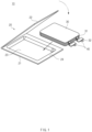
- FIG. 1 is a perspective view illustrating an example of a pouch-type secondary battery.
- a pouch-type secondary battery 10 may include an electrode assembly 30 in which a plurality of electrodes and separators are alternately stacked and a pouch 20 which accommodates the electrode assembly 30.
- the electrode assembly 30 may be provided with a plurality of tab 31 which extend from the plurality of electrodes and are fused to each other and an electrode lead 32 which is bonded to the plurality of tabs 31 fused to each other.
- the electrode lead 32 may protrude outward from the pouch 20 and may be easily electrically connected to a power supply target (e.g., a motor or the like).
- the pouch 20 may include: a pouch body 21 having an accommodation portion 23 which has a recessed shape and to which the electrode assembly 30 is mounted; and a pouch cover 22 bonded to the pouch body 21 to seal the accommodation portion 23.
- the pouch body 21 and the pouch cover 22 may be integrally connected to or separated from each other. Also, it is possible that a sub accommodation portion (not shown) that has a recessed shape corresponding to the accommodation portion 23 is formed in the pouch cover 22.
- the pouch body 21 may include a facing surface 24 that is positioned in the outside of the accommodation portion 23 and faces the pouch cover 22, and at least a portion of the facing surface 24 may be bonded to the pouch cover 22 by thermal fusion. That is, a sealing portion of the pouch 20 may be sealed as at least a portion of the facing surface 24 is bonded to the pouch cover 22.
- a lead film 40 may be attached to each of both surfaces of the electrode lead 32 not only to prevent a short circuit from occurring in the electrode lead 32 while the sealing portion of the pouch 20 is sealed, but also to ensure sealing between the electrode lead 32 and the pouch 20.
- a region, which is present in a sealing portion of the pouch 20 and adjacent to the lead film 40 may have a complicated shape when compared to the other regions and may have different thickness. Accordingly, in a manufacturing method according to the related art, in which a sealing portion of the pouch 20 is compressed and sealed by a heating bar, it is difficult to ensure uniform sealing quality, and a time required to seal is lengthened.
- the manufacturing method according to the related art includes heating the electrode lead 32 prior to sealing the sealing portion of the pouch 20. This is to prevent heat of the heating bar, which seals the sealing portion of the pouch 20, from being conducted to a cold electrode lead 32.
- a separate lead heater is required due to the above reason, and accordingly, costs of a manufacturing apparatus is increased, and temperature control becomes complicated.
- Patent document KR 10-2012-0056316 A (published on June 04, 2012 ) can be cited as a prior art document.
- An object of the present invention for solving the above problems is to provide a method and apparatus for manufacturing a pouch-type secondary battery, which can reduce a sealing time and enhance sealing quality.
- a method for manufacturing a pouch-type secondary battery of the present invention includes: a first sealing operation of irradiating with a laser beam a region which is present in a sealing portion of a pouch and corresponds to a lead film and compressing the same; and a second sealing operation of sealing the sealing portion of the pouch.
- a method for manufacturing a pouch-type secondary battery may include: a first sealing operation of fusing a lead film, which is attached to an electrode lead of an electrode assembly, to a sealing portion of a pouch in which the electrode assembly is accommodated; and a second sealing operation of sealing the sealing portion of the pouch.
- the first sealing operation may include: a heating process of irradiating with a laser beam a region which is present in the sealing portion of the pouch and corresponds to the lead film, thereby heating the lead film and melting a resin layer of the region; and a bonding process of compressing the region, thereby bonding the lead film and the melted resin layer.
- the first sealing operation and the second sealing operation may be sequentially conducted.
- the region sealed in the first sealing operation may be included in the sealing portion sealed in the second sealing operation.
- a length of the region with respect to a width direction of the lead film may be greater than or equal to a width of the lead film.
- the heating process and the bonding process may be simultaneously performed.
- the laser beam may be an infrared laser beam having a wavelength of 808 nm to 980 nm.
- a laser unit performing the first sealing operation may include: a light source configured to emit a laser beam; and a compression part compressing the region which is present in the sealing portion of the pouch and corresponds to the lead film, the compression part having a transparent or translucent material through which the laser beam is transmitted.
- the light source may emit the laser beam in a state in which the compression part compresses the region.
- the sealing tool may include a heating bar that compresses the sealing portion.
- a temperature of the compression part when the region is compressed may be lower than a temperature of the heating bar when the sealing portion is compressed.
- the region sealed in the first sealing operation may be excluded from the sealing portion sealed in the second sealing operation.
- An apparatus for manufacturing a pouch-type secondary battery may include: a laser unit configured to fuse a lead film, which is attached to an electrode lead of an electrode assembly, to a sealing portion of a pouch in which the electrode assembly is accommodated; and a sealing tool configured to seal the sealing portion of the pouch after the lead film is fused to the sealing portion.
- the laser unit may include: a light source configured to emit a laser beam; and a compression part configured to compress a region which is present in the sealing portion of the pouch and corresponds to the lead film, the compression part having a transparent or translucent material through which the laser beam is transmitted.
- the apparatus may further include an optical part configured to guide the laser beam, which is emitted from the light source, to the compression part.
- the compression part may have a quartz material.
- the compression part may refract or reflect the laser beam emitted from the light source.
- a first sealing operation may be provided, in which a region, which is present in a sealing portion of a pouch and corresponds to a lead film, is irradiated with a laser beam and compressed. Accordingly, compared to a sealing method according to the related art, sealing quality in a region near a lead film having a complicated shape may be enhanced, and the time consumed in sealing may be reduced.
- a laser unit has a compact size, and equipment costs are reduced.
- the irradiation time and intensity of the laser beam may be adjusted.
- a separate lead heater for preheating the electrode lead is not necessary.
- the sealing quality of the region is maintained high.
- a length of the region with respect to a width direction of the lead film may be greater than or equal to a width of the lead film. Accordingly, the lead film may be reliably thermally fused to the sealing portion.
- a heating process and a bonding process of the first sealing operation may be simultaneously performed. Accordingly, a resin melted in the heating process may be reliably thermally fused to the lead film.
- a compression part of the laser unit may compress the region and also allow the laser beam to be transmitted therethrough. Also, the compression part itself may serve as an optical part. Accordingly, the configuration of the laser unit becomes simple and compact.
- the compression part may include a quartz material. Accordingly, the compression part may sufficiently firmly compress the region while allowing the laser beam to be transmitted therethrough.
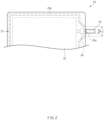
- FIG. 2 is a plan view of a pouch-type secondary battery which is formed according to a method for manufacturing a pouch-type secondary battery according to an embodiment of the present invention.
- a pouch 20 may include a sealing portion 25.
- the sealing portion 25 may form a closed loop that extends along the circumferential direction of the pouch 20.
- the sealing portion 25 may represent a portion sealed in the pouch 20. Also, before sealing of the pouch 20 is completed, the sealing portion 25 may represent a portion to be sealed in each of a pouch body 21 and a pouch cover 22.
- the sealing portion 25 may include a first region 25a corresponding to a lead film 40 and a second region 25b except for the first region 25a.
- the first region 25a and the second region 25b may be sealed through different methods, and this will be described later in detail.
- the second region 25b may be sealed by thermally fusing a facing surface 24 of the pouch body 21 and the pouch cover 22.
- the first region 25a may be sealed by thermal fusion with the lead film 40.
- a lead film 40 attached to one surface of an electrode lead 32 may be thermally fused to the pouch cover 22, and a lead film 40 attached to the other surface of the electrode lead 32 may be thermally fused to the facing surface 24 of the pouch body 21.
- a length L of the first region 25a with respect to the width direction of the lead film 40 may be greater than or equal to a width W of the lead film 40. That is, the first region 25a may include not only a region directly facing the lead film 40 but also a region adjacent thereto.
- the entire first region 25a may be thermally fused to the lead film 40 and sealed.
- ends of the first region 25a out of the lead film 40 may be sealed as the facing surface 24 of the pouch body 21 is thermally fused with the pouch cover 22.
- FIG. 3 is a flowchart illustrating a method for manufacturing a pouch-type secondary battery according to an embodiment of the present invention.
- the method for manufacturing a pouch-type secondary battery may include a first sealing operation (S10) of fusing a lead film 40 to a sealing portion 25 of a pouch 20 through a laser beam and a second sealing operation (S20) of sealing the sealing portion 25 of the pouch 20.
- the first sealing operation (S10) may be pre-sealing, and the second sealing operation (S20) may be main-sealing. That is, the first sealing operation (S10) and the second sealing operation (S20) may be sequentially conducted.
- the first sealing operation (S10) and the second sealing operation 20 may be conducted in different stages, and an operation of injecting an electrolyte into an accommodation portion 23 of the pouch 20 may be conducted between the first sealing operation (S10) and the second sealing operation (S20).
- the first sealing operation (S10) may thermally fuse a first region 25a and the lead film 40.
- the first sealing operation (S10) may be performed by a laser unit 60 (see FIG. 5 ) which will be described later.
- the first sealing operation (S10) may include: a heating process of irradiating with a laser beam the first region 25a which is present in the sealing portion 25 of the pouch 20 and corresponds to the lead film 40, thereby heating the lead film 40 and melting resin layers 21c and 22c (see FIG. 4 ) of the first region 25a; and a bonding process of compressing the first region 25a, thereby bonding the lead film 40 and the melted resin layers 21c and 22c. This will be described later in detail.
- the second sealing operation (S20) may seal the entire sealing portion 25, that is, both the first region 25a and a second region 25b.
- the second sealing operation (S20) may be performed in a different way from the first sealing operation (S10) .
- the second sealing operation (S20) may be performed by a sealing tool 50 (see FIG. 4 ) which will be described later.
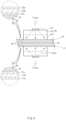
- FIG. 4 is a schematic view illustrating an example of a laser unit for performing a first sealing operation.
- An apparatus for manufacturing a pouch-type secondary battery according to an embodiment of the present invention may include the laser unit 60 that performs the first sealing operation (S10).
- the laser unit 60 may fuse the lead film 40 to the sealing portion 25 of the pouch 20, more specifically, to the first region 25a.
- a pouch body 21 and a pouch cover 22, which constitute the pouch 20, may be made of laminate sheets that include inner resin layers 21c and 22c, respectively.
- the pouch body 21 and the pouch cover 22 may respectively include: outer resin layers 21a and 22a constituting a portion of the exterior of the pouch 20; inner resin layers 21c and 22c for sealing; and metal layers 21b and 22b positioned between the outer resin layers 21a and 22a and the inner resin layers 21c and 22c.
- the outer resin layers 21a and 22a may include polyethylene terephthalate (PET) materials
- the metal layers 21b and 22b may include aluminium (AL) materials
- the inner resin layers 21c and 22c may include polypropylene (PP) materials.
- the laser unit 60 may irradiate with the laser beam the first region 25a of the sealing portion 25 of the pouch 20, and may compress the first region 25b.
- the inner resin layers 21c and 22c of the first region 25a of the pouch 20 may be melted and thermally fused to the lead film 40.
- the lead film 40 also has a resin material (e.g., polypropylene), and thus, a portion of the lead film 40 may be melted by the laser beam emitted from the laser unit 60.
- the thermal fusion between the lead film 40 and the inner resin layers 21c and 22c may be more reliably made.
- the laser unit 60 may include a light source 61, a compression part 62, and an optical part 63.
- the light source 61 may emit laser having a beam shape.
- the light source 61 may be a laser diode.
- the laser beam emitted from the light source 61 may be an infrared laser beam, and more specifically, an infrared laser beam having a wavelength of 808 nm to 980 nm.
- the light source 61 may be provided in plurality. Some of the plurality of light sources 61 may be positioned above the pouch 20 and referred to as upper light sources, and the others of the plurality of light sources 61 may be positioned below the sealing portion 25 and referred to as lower light sources.
- the laser beams emitted from the upper light sources 61 may heat the lead film 40 attached to the upper side of the electrode lead 32 and the first region 25a of the pouch cover 22.
- the laser beams emitted from the lower light sources 61 may heat the lead film 40 attached to the lower side of the electrode lead 32 and the first region 25a of the pouch body 21.
- the compression part 62 may compress the first region 25a.
- the compression part 62 may have a transparent or translucent material through which the laser beam emitted from the light source 61 is transmitted.
- the compression part 62 may include a quartz material having high strength. Accordingly, the compression part 62 may allow the laser beam to be transmitted therethrough while sufficiently firmly compressing the first region 25a.
- the temperature of the compression part 62 of the laser unit 60 when compressing the first region 25a may be lower than the temperature of a heating bar 50 that compresses the sealing portion 25 during the second sealing operation. This is because the laser beam emitted from the light source 61 is transmitted through the compression part 62, as opposed to heating the same. Thus, energy loss may be reduced.
- a pair of compression parts 62 may be provided.
- the pair of compression parts 62 facing each other with the first region 25a therebetween may move in directions to become closer to each other and compress the first region 25a. It is apparent that the manufacturing apparatus includes a raising/lowering mechanism that raises and lowers the compression parts 62.
- FIG. 4 illustrates that the light source 61 and the optical part 63 move together with the compression parts 62, but this is not limited thereto. It is possible for the compression parts 62 to move solely.
- a compression part 62 positioned above the pouch 20 may compress downward the first region 25a of the pouch cover 22 and may be referred to as an upper compression part.
- a compression part 62 positioned below the pouch 20 may compress upward the first region 25a of the pouch body 21 and may be referred to as a lower compression part.
- the laser beams emitted from the upper light source 61 may pass through the upper compression part 62 and then thermally fuse the lead film 40 attached to the upper side of the electrode lead 32 and the inner resin layer 22c of the pouch cover 22.
- the laser beams emitted from the lower light source may pass through the upper compression part and then thermally fuse the lead film 40 attached to the lower side of the electrode lead 32 and the inner resin layer 21c of the pouch body 21.
- the optical part 63 may be positioned between the light source 61 and the compression part 62 along the path of the laser beams.
- the optical part 63 may refract and/or reflect the laser beam emitted from the light source 61 and guide the same to the compression part 62.
- the optical part 63 may include at least one of a lens and a reflector.
- the optical part 63 may be formed integrally with the compression part 62 or may be provided as a separate member. Like the compression parts 62, at least a pair of optical parts 63 may be provided.
- the laser beams emitted from the light source 61 may be superposed with each other after passing through the optical part 63 and the compression part 62, and may be simultaneously emitted to the entire region which is present in the pouch body 21 and compressed by the compression part 62. Also, the region may be heated from 200 degrees Celsius to 250 degrees Celsius by the laser beam.
- the first sealing operation (S10) may be initiated in a state in which the pouch 20 is aligned so that the first region 25a of the sealing portion 25 is positioned between the at least one pair of the compression parts 62.
- the first sealing operation (S10) may include: a heating process of irradiating the first region 25a of the sealing portion 25 with the laser beam to heat the lead film 40, thereby melting the inner resin layers 21c and 22c of the first region 25a; and a bonding process of compressing the first region 25a, thereby bonding the lead film 40 and the melted resin layers 21c and 22c.
- the heating process may be performed, as the laser beam emitted from the light source 61 is guided to the compression part 62 by the optical part 63, transmitted through the compression part 62, and then emitted to the first region 25a.
- the inner resin layers 21c and 22c of the first region 25a may be melted by the laser beam emitted to the first region 25a.
- the inner resin layers 21c and 22c of the first region 25a may be reliably melted even if the electrode lead 32 is in a cold state.
- a separate lead heater (not shown) is not necessary.
- the bonding process may be performed as the compression part 62 compresses the first region 25a.
- the pair of compression parts 62 facing each other may move in directions to become closer to each other and compress the first region 25a.
- the inner resin layers 21c and 22c of the first region 25a melted by the heating process may be bonded to the lead film 40.
- the heating process and the bonding process may be simultaneously performed. That is, the light source 61 may emit the laser beam in a state in which the compression parts 62 compress the first region 25a.
- FIG. 5 is a schematic view illustrating another example of a laser unit for performing a first sealing operation.
- a laser unit 60' does not include a separate optical part, and a compression part 62' may serve as an optical part.
- the compression part 62' itself may function as a reflector or a lens.
- a light source 61 may directly emit a laser beam toward the compression part 62', and the laser beam may be refracted or reflected within the compression part 62' and then emitted to a first region 25a. Accordingly, the laser unit 60' has a compact size, and the structure thereof is simplified.
- FIG. 6 is a schematic view illustrating a sealing tool for performing a second sealing operation.
- An apparatus for manufacturing a pouch-type secondary battery according to an embodiment of the present invention may include a sealing tool 50 that performs the second sealing operation (S20).
- the sealing tool 50 may seal a sealing portion 25 by thermally fusing a pouch body 21 and a pouch cover 22.
- the sealing tool 50 may include at least a pair of heating bars 50 which are disposed facing each other with a pouch 20 therebetween (for convenience, the same reference numeral '50' is used for the sealing tool and the heating bars). It is apparent that the sealing tool 50 includes a heater for heating a heating bar 50 and a raising/lowering mechanism for raising and lowering the heating bar 50.
- At least the pair of the heating bars 50 in a heated state may move in directions to become closer to each other and compress the sealing portion 25 of the pouch 20.
- an inner resin layer 21c of the sealing portion 25 of the pouch body 21 and an inner resin layer 22c of the sealing portion 25 of the pouch cover 22 may be melted and thermally fused to each other.
- the heating bars 50 may compress the first region 25a as well as a second region 25b together.
- FIG. 7 is a flowchart illustrating a method for manufacturing a pouch-type secondary battery according to another embodiment of the present invention.
- a first sealing operation (S10) is identical to the first sealing operation (S10) of the above-described embodiment, and thus, the description thereof may be applied thereto.
- a second sealing operation (S20') may seal only a second region 25b of a sealing portion 25 of a pouch 20 except for a first region 25a. That is, a heating bar 50 may compress only the second region 25b except for the first region 25a.
- FIG. 7 illustrates that the first sealing operation (S10) and the second sealing operation (S20) are performed in this order, but the embodiment is not limited thereto.
- the first sealing operation (S10) may be performed after the second sealing operation (S20').
- Pouch-type secondary battery 20 Pouch 21: Pouch body 22: Pouch cover 23: Accommodation portion 24: Facing surface 25: Sealing portion 25a: First region 25b: Second region 30: Electrode assembly 31: Tab 32: Electrode lead 40: Lead film 50: Sealing tool 60: Laser unit 61: Light source 62: Compression part 63: Optical part
Landscapes
- Engineering & Computer Science (AREA)
- Physics & Mathematics (AREA)
- Chemical Kinetics & Catalysis (AREA)
- General Chemical & Material Sciences (AREA)
- Electrochemistry (AREA)
- Chemical & Material Sciences (AREA)
- Mechanical Engineering (AREA)
- Optics & Photonics (AREA)
- Toxicology (AREA)
- Health & Medical Sciences (AREA)
- Electromagnetism (AREA)
- Manufacturing & Machinery (AREA)
- Sealing Battery Cases Or Jackets (AREA)
Abstract
Description
- The present application claims the benefit of the priority of
Korean Patent Application No. 10-2020-0156017, filed on November 19, 2020 - The present invention relates to a method and apparatus for manufacturing a secondary battery and, more specifically, to a method and apparatus for manufacturing a pouch-type secondary battery.
- Recently, the price of energy sources is increasing due to the depletion of fossil fuels, interest in environmental pollution is growing, and demands for eco-friendly alternative energy sources have become an indispensable factor for the future life. Accordingly, research on technologies for generating various powers such as photovoltaic, wind, and tidal powers is continuing, and power storage devices such as batteries for more efficiently using the generated electric energy are also drawing much attention.
- Furthermore, as technical development and demands for electronic mobile devices and electric vehicles using batteries increase, demands for batteries as energy sources are rapidly increasing. Accordingly, lots of research on the batteries capable of coping with these various demands are being carried out.
- In particular, in terms of materials, there are high demands for lithium secondary batteries, such as lithium ion batteries and lithium ion polymer batteries, having advantages such as the high energy density and discharge voltage and the output stability.
- Depending on the shape of a battery case, secondary batteries may be classified as a cylindrical or prismatic battery in which an electrode assembly is embedded in a cylindrical or prismatic metal can and a pouch-type battery in which an electrode assembly is embedded in a pouch made of an aluminum laminate sheet.
-
FIG. 1 is a perspective view illustrating an example of a pouch-type secondary battery. - Referring to
FIG. 1 , a pouch-typesecondary battery 10 may include anelectrode assembly 30 in which a plurality of electrodes and separators are alternately stacked and apouch 20 which accommodates theelectrode assembly 30. Theelectrode assembly 30 may be provided with a plurality oftab 31 which extend from the plurality of electrodes and are fused to each other and anelectrode lead 32 which is bonded to the plurality oftabs 31 fused to each other. Theelectrode lead 32 may protrude outward from thepouch 20 and may be easily electrically connected to a power supply target (e.g., a motor or the like). - The
pouch 20 may include: apouch body 21 having anaccommodation portion 23 which has a recessed shape and to which theelectrode assembly 30 is mounted; and apouch cover 22 bonded to thepouch body 21 to seal theaccommodation portion 23. Before theelectrode assembly 30 is accommodated, thepouch body 21 and thepouch cover 22 may be integrally connected to or separated from each other. Also, it is possible that a sub accommodation portion (not shown) that has a recessed shape corresponding to theaccommodation portion 23 is formed in thepouch cover 22. - Also, the
pouch body 21 may include a facingsurface 24 that is positioned in the outside of theaccommodation portion 23 and faces thepouch cover 22, and at least a portion of the facingsurface 24 may be bonded to thepouch cover 22 by thermal fusion. That is, a sealing portion of thepouch 20 may be sealed as at least a portion of the facingsurface 24 is bonded to thepouch cover 22. - A
lead film 40 may be attached to each of both surfaces of theelectrode lead 32 not only to prevent a short circuit from occurring in theelectrode lead 32 while the sealing portion of thepouch 20 is sealed, but also to ensure sealing between theelectrode lead 32 and thepouch 20. Thus, a region, which is present in a sealing portion of thepouch 20 and adjacent to thelead film 40, may have a complicated shape when compared to the other regions and may have different thickness. Accordingly, in a manufacturing method according to the related art, in which a sealing portion of thepouch 20 is compressed and sealed by a heating bar, it is difficult to ensure uniform sealing quality, and a time required to seal is lengthened. - Also, the manufacturing method according to the related art includes heating the
electrode lead 32 prior to sealing the sealing portion of thepouch 20. This is to prevent heat of the heating bar, which seals the sealing portion of thepouch 20, from being conducted to acold electrode lead 32. However, a separate lead heater is required due to the above reason, and accordingly, costs of a manufacturing apparatus is increased, and temperature control becomes complicated. - Patent document
KR 10-2012-0056316 A (published on June 04, 2012 - An object of the present invention for solving the above problems is to provide a method and apparatus for manufacturing a pouch-type secondary battery, which can reduce a sealing time and enhance sealing quality.
- A method for manufacturing a pouch-type secondary battery of the present invention includes: a first sealing operation of irradiating with a laser beam a region which is present in a sealing portion of a pouch and corresponds to a lead film and compressing the same; and a second sealing operation of sealing the sealing portion of the pouch.
- In more detail, a method for manufacturing a pouch-type secondary battery according to an embodiment of the present invention may include: a first sealing operation of fusing a lead film, which is attached to an electrode lead of an electrode assembly, to a sealing portion of a pouch in which the electrode assembly is accommodated; and a second sealing operation of sealing the sealing portion of the pouch. The first sealing operation may include: a heating process of irradiating with a laser beam a region which is present in the sealing portion of the pouch and corresponds to the lead film, thereby heating the lead film and melting a resin layer of the region; and a bonding process of compressing the region, thereby bonding the lead film and the melted resin layer.
- The first sealing operation and the second sealing operation may be sequentially conducted.
- The region sealed in the first sealing operation may be included in the sealing portion sealed in the second sealing operation.
- A length of the region with respect to a width direction of the lead film may be greater than or equal to a width of the lead film.
- The heating process and the bonding process may be simultaneously performed.
- The laser beam may be an infrared laser beam having a wavelength of 808 nm to 980 nm.
- A laser unit performing the first sealing operation may include: a light source configured to emit a laser beam; and a compression part compressing the region which is present in the sealing portion of the pouch and corresponds to the lead film, the compression part having a transparent or translucent material through which the laser beam is transmitted.
- The light source may emit the laser beam in a state in which the compression part compresses the region.
- The sealing tool may include a heating bar that compresses the sealing portion. A temperature of the compression part when the region is compressed may be lower than a temperature of the heating bar when the sealing portion is compressed.
- The region sealed in the first sealing operation may be excluded from the sealing portion sealed in the second sealing operation.
- An apparatus for manufacturing a pouch-type secondary battery according to an embodiment of the present invention may include: a laser unit configured to fuse a lead film, which is attached to an electrode lead of an electrode assembly, to a sealing portion of a pouch in which the electrode assembly is accommodated; and a sealing tool configured to seal the sealing portion of the pouch after the lead film is fused to the sealing portion. The laser unit may include: a light source configured to emit a laser beam; and a compression part configured to compress a region which is present in the sealing portion of the pouch and corresponds to the lead film, the compression part having a transparent or translucent material through which the laser beam is transmitted.
- The apparatus may further include an optical part configured to guide the laser beam, which is emitted from the light source, to the compression part.
- The compression part may have a quartz material.
- The compression part may refract or reflect the laser beam emitted from the light source.
- According to a preferred embodiment of the present invention, a first sealing operation may be provided, in which a region, which is present in a sealing portion of a pouch and corresponds to a lead film, is irradiated with a laser beam and compressed. Accordingly, compared to a sealing method according to the related art, sealing quality in a region near a lead film having a complicated shape may be enhanced, and the time consumed in sealing may be reduced.
- Also, only the region describe above is irradiated by a laser beam. Thus, a laser unit has a compact size, and equipment costs are reduced.
- Also, the irradiation time and intensity of the laser beam may be adjusted. Thus, a separate lead heater for preheating the electrode lead is not necessary.
- Also, when a second sealing operation seals regions including the above-described region, the sealing of the region is more strengthened.
- Also, when the second sealing operation seals regions excluding the above-described region, the sealing quality of the region is maintained high.
- Also, a length of the region with respect to a width direction of the lead film may be greater than or equal to a width of the lead film. Accordingly, the lead film may be reliably thermally fused to the sealing portion.
- Also, a heating process and a bonding process of the first sealing operation may be simultaneously performed. Accordingly, a resin melted in the heating process may be reliably thermally fused to the lead film.
- Also, a compression part of the laser unit may compress the region and also allow the laser beam to be transmitted therethrough. Also, the compression part itself may serve as an optical part. Accordingly, the configuration of the laser unit becomes simple and compact.
- Also, the compression part may include a quartz material. Accordingly, the compression part may sufficiently firmly compress the region while allowing the laser beam to be transmitted therethrough.
-
-
FIG. 1 is a perspective view illustrating an example of a pouch-type secondary battery. -
FIG. 2 is a plan view of a pouch-type secondary battery which is formed according to a method for manufacturing a pouch-type secondary battery according to the present invention. -
FIG. 3 is a flowchart illustrating a method for manufacturing a pouch-type secondary battery according to an embodiment of the present invention. -
FIG. 4 is a schematic view illustrating an example of a laser unit for performing a first sealing operation. -
FIG. 5 is a schematic view illustrating another example of a laser unit for performing a first sealing operation. -
FIG. 6 is a schematic view illustrating a sealing tool for performing a second sealing operation. -
FIG. 7 is a flowchart illustrating a method for manufacturing a pouch-type secondary battery according to another embodiment of the present invention. - Hereinafter, preferred embodiments of the present invention will be described in detail with reference to the accompanying drawings so as to be easily carried out by a person skilled in the art to which the present invention pertains. However, the present invention may be embodied in various different forms, and is neither limited nor restricted to the following embodiments.
- In order to clearly describe the present invention, parts irrelevant to the description are omitted, and descriptions related to well-known functions or configurations are ruled out so as not to unnecessarily obscure subject matters of the present invention. In the specification, when reference numerals are given to components in each of the drawings, the same or similar components will be designated by the same or similar reference numerals throughout the specification.
- Also, terms or words used in this specification and claims should not be restrictively interpreted as ordinary meanings or dictionary-based meanings, but should be interpreted as meanings and concepts conforming to the technical ideas of the present invention on the basis of the principle that an inventor can properly define the concept of a term to describe his or her invention in the best ways.
-
FIG. 2 is a plan view of a pouch-type secondary battery which is formed according to a method for manufacturing a pouch-type secondary battery according to an embodiment of the present invention. - Referring to
FIGS. 1 and2 , apouch 20 may include a sealingportion 25. The sealingportion 25 may form a closed loop that extends along the circumferential direction of thepouch 20. - When sealing of the
pouch 20 is completed, the sealingportion 25 may represent a portion sealed in thepouch 20. Also, before sealing of thepouch 20 is completed, the sealingportion 25 may represent a portion to be sealed in each of apouch body 21 and apouch cover 22. - In more detail, the sealing
portion 25 may include afirst region 25a corresponding to alead film 40 and asecond region 25b except for thefirst region 25a. Thefirst region 25a and thesecond region 25b may be sealed through different methods, and this will be described later in detail. - The
second region 25b may be sealed by thermally fusing a facingsurface 24 of thepouch body 21 and thepouch cover 22. - The
first region 25a may be sealed by thermal fusion with thelead film 40. In more detail, alead film 40 attached to one surface of anelectrode lead 32 may be thermally fused to thepouch cover 22, and alead film 40 attached to the other surface of theelectrode lead 32 may be thermally fused to the facingsurface 24 of thepouch body 21. - A length L of the
first region 25a with respect to the width direction of thelead film 40 may be greater than or equal to a width W of thelead film 40. That is, thefirst region 25a may include not only a region directly facing thelead film 40 but also a region adjacent thereto. - In more detail, when the length L of the
first region 25a is equal to the width W of thelead film 40, the entirefirst region 25a may be thermally fused to thelead film 40 and sealed. On the other hand, when the length L of thefirst region 25a is greater than the width W of thelead film 40, ends of thefirst region 25a out of thelead film 40 may be sealed as the facingsurface 24 of thepouch body 21 is thermally fused with thepouch cover 22. -
FIG. 3 is a flowchart illustrating a method for manufacturing a pouch-type secondary battery according to an embodiment of the present invention. - Referring to
FIG. 3 , the method for manufacturing a pouch-type secondary battery according to the embodiment may include a first sealing operation (S10) of fusing alead film 40 to a sealingportion 25 of apouch 20 through a laser beam and a second sealing operation (S20) of sealing the sealingportion 25 of thepouch 20. - The first sealing operation (S10) may be pre-sealing, and the second sealing operation (S20) may be main-sealing. That is, the first sealing operation (S10) and the second sealing operation (S20) may be sequentially conducted.
- The first sealing operation (S10) and the
second sealing operation 20 may be conducted in different stages, and an operation of injecting an electrolyte into anaccommodation portion 23 of thepouch 20 may be conducted between the first sealing operation (S10) and the second sealing operation (S20). - In more detail, the first sealing operation (S10) may thermally fuse a
first region 25a and thelead film 40. The first sealing operation (S10) may be performed by a laser unit 60 (seeFIG. 5 ) which will be described later. - In more detail, the first sealing operation (S10) may include: a heating process of irradiating with a laser beam the
first region 25a which is present in the sealingportion 25 of thepouch 20 and corresponds to thelead film 40, thereby heating thelead film 40 and melting resin layers 21c and 22c (seeFIG. 4 ) of thefirst region 25a; and a bonding process of compressing thefirst region 25a, thereby bonding thelead film 40 and the melted resin layers 21c and 22c. This will be described later in detail. - The second sealing operation (S20) may seal the
entire sealing portion 25, that is, both thefirst region 25a and asecond region 25b. The second sealing operation (S20) may be performed in a different way from the first sealing operation (S10) . The second sealing operation (S20) may be performed by a sealing tool 50 (seeFIG. 4 ) which will be described later. -
FIG. 4 is a schematic view illustrating an example of a laser unit for performing a first sealing operation. - An apparatus for manufacturing a pouch-type secondary battery according to an embodiment of the present invention (hereinafter, referred to as a 'manufacturing apparatus') may include the
laser unit 60 that performs the first sealing operation (S10). Thelaser unit 60 may fuse thelead film 40 to the sealingportion 25 of thepouch 20, more specifically, to thefirst region 25a. - A
pouch body 21 and apouch cover 22, which constitute thepouch 20, may be made of laminate sheets that include inner resin layers 21c and 22c, respectively. In more detail, thepouch body 21 and thepouch cover 22 may respectively include:outer resin layers pouch 20; inner resin layers 21c and 22c for sealing; andmetal layers outer resin layers outer resin layers - The
laser unit 60 may irradiate with the laser beam thefirst region 25a of the sealingportion 25 of thepouch 20, and may compress thefirst region 25b. Thus, the inner resin layers 21c and 22c of thefirst region 25a of thepouch 20 may be melted and thermally fused to thelead film 40. Also, thelead film 40 also has a resin material (e.g., polypropylene), and thus, a portion of thelead film 40 may be melted by the laser beam emitted from thelaser unit 60. Thus, the thermal fusion between thelead film 40 and the inner resin layers 21c and 22c may be more reliably made. - In more detail, the
laser unit 60 may include alight source 61, acompression part 62, and an optical part 63. - The
light source 61 may emit laser having a beam shape. For example, thelight source 61 may be a laser diode. The laser beam emitted from thelight source 61 may be an infrared laser beam, and more specifically, an infrared laser beam having a wavelength of 808 nm to 980 nm. - The
light source 61 may be provided in plurality. Some of the plurality oflight sources 61 may be positioned above thepouch 20 and referred to as upper light sources, and the others of the plurality oflight sources 61 may be positioned below the sealingportion 25 and referred to as lower light sources. - The laser beams emitted from the upper
light sources 61 may heat thelead film 40 attached to the upper side of theelectrode lead 32 and thefirst region 25a of thepouch cover 22. The laser beams emitted from thelower light sources 61 may heat thelead film 40 attached to the lower side of theelectrode lead 32 and thefirst region 25a of thepouch body 21. - The
compression part 62 may compress thefirst region 25a. Thecompression part 62 may have a transparent or translucent material through which the laser beam emitted from thelight source 61 is transmitted. For example, thecompression part 62 may include a quartz material having high strength. Accordingly, thecompression part 62 may allow the laser beam to be transmitted therethrough while sufficiently firmly compressing thefirst region 25a. - The temperature of the
compression part 62 of thelaser unit 60 when compressing thefirst region 25a may be lower than the temperature of aheating bar 50 that compresses the sealingportion 25 during the second sealing operation. This is because the laser beam emitted from thelight source 61 is transmitted through thecompression part 62, as opposed to heating the same. Thus, energy loss may be reduced. - A pair of
compression parts 62 may be provided. The pair ofcompression parts 62 facing each other with thefirst region 25a therebetween may move in directions to become closer to each other and compress thefirst region 25a. It is apparent that the manufacturing apparatus includes a raising/lowering mechanism that raises and lowers thecompression parts 62. -
FIG. 4 illustrates that thelight source 61 and the optical part 63 move together with thecompression parts 62, but this is not limited thereto. It is possible for thecompression parts 62 to move solely. - In more detail, a
compression part 62 positioned above thepouch 20 may compress downward thefirst region 25a of thepouch cover 22 and may be referred to as an upper compression part. Acompression part 62 positioned below thepouch 20 may compress upward thefirst region 25a of thepouch body 21 and may be referred to as a lower compression part. - The laser beams emitted from the upper
light source 61 may pass through theupper compression part 62 and then thermally fuse thelead film 40 attached to the upper side of theelectrode lead 32 and theinner resin layer 22c of thepouch cover 22. The laser beams emitted from the lower light source may pass through the upper compression part and then thermally fuse thelead film 40 attached to the lower side of theelectrode lead 32 and theinner resin layer 21c of thepouch body 21. - The optical part 63 may be positioned between the
light source 61 and thecompression part 62 along the path of the laser beams. The optical part 63 may refract and/or reflect the laser beam emitted from thelight source 61 and guide the same to thecompression part 62. For example, the optical part 63 may include at least one of a lens and a reflector. The optical part 63 may be formed integrally with thecompression part 62 or may be provided as a separate member. Like thecompression parts 62, at least a pair of optical parts 63 may be provided. - The laser beams emitted from the
light source 61 may be superposed with each other after passing through the optical part 63 and thecompression part 62, and may be simultaneously emitted to the entire region which is present in thepouch body 21 and compressed by thecompression part 62. Also, the region may be heated from 200 degrees Celsius to 250 degrees Celsius by the laser beam. - Hereinafter, an operation of the
laser unit 60 during the first sealing operation (S10) will be described in detail. - The first sealing operation (S10) may be initiated in a state in which the
pouch 20 is aligned so that thefirst region 25a of the sealingportion 25 is positioned between the at least one pair of thecompression parts 62. - The first sealing operation (S10) may include: a heating process of irradiating the
first region 25a of the sealingportion 25 with the laser beam to heat thelead film 40, thereby melting the inner resin layers 21c and 22c of thefirst region 25a; and a bonding process of compressing thefirst region 25a, thereby bonding thelead film 40 and the melted resin layers 21c and 22c. - The heating process may be performed, as the laser beam emitted from the
light source 61 is guided to thecompression part 62 by the optical part 63, transmitted through thecompression part 62, and then emitted to thefirst region 25a. The inner resin layers 21c and 22c of thefirst region 25a may be melted by the laser beam emitted to thefirst region 25a. - Also, since the irradiation time or intensity of the laser beam may be adjusted, the inner resin layers 21c and 22c of the
first region 25a may be reliably melted even if theelectrode lead 32 is in a cold state. Thus, since theelectrode lead 32 does not need to be pre-heated, a separate lead heater (not shown) is not necessary. - The bonding process may be performed as the
compression part 62 compresses thefirst region 25a. In more detail, the pair ofcompression parts 62 facing each other may move in directions to become closer to each other and compress thefirst region 25a. Thus, the inner resin layers 21c and 22c of thefirst region 25a melted by the heating process may be bonded to thelead film 40. - Since the
first region 25a is irradiated with the laser beam in a compressed state, the heating process and the bonding process may be simultaneously performed. That is, thelight source 61 may emit the laser beam in a state in which thecompression parts 62 compress thefirst region 25a. -
FIG. 5 is a schematic view illustrating another example of a laser unit for performing a first sealing operation. - A laser unit 60' according to the embodiment does not include a separate optical part, and a compression part 62' may serve as an optical part. For example, the compression part 62' itself may function as a reflector or a lens. Thus, a
light source 61 may directly emit a laser beam toward the compression part 62', and the laser beam may be refracted or reflected within the compression part 62' and then emitted to afirst region 25a. Accordingly, the laser unit 60' has a compact size, and the structure thereof is simplified. -
FIG. 6 is a schematic view illustrating a sealing tool for performing a second sealing operation. - An apparatus for manufacturing a pouch-type secondary battery according to an embodiment of the present invention (hereinafter, referred to as a 'manufacturing apparatus') may include a
sealing tool 50 that performs the second sealing operation (S20). The sealingtool 50 may seal a sealingportion 25 by thermally fusing apouch body 21 and apouch cover 22. - The sealing
tool 50 may include at least a pair of heating bars 50 which are disposed facing each other with apouch 20 therebetween (for convenience, the same reference numeral '50' is used for the sealing tool and the heating bars). It is apparent that the sealingtool 50 includes a heater for heating aheating bar 50 and a raising/lowering mechanism for raising and lowering theheating bar 50. - At least the pair of the heating bars 50 in a heated state may move in directions to become closer to each other and compress the sealing
portion 25 of thepouch 20. Thus, aninner resin layer 21c of the sealingportion 25 of thepouch body 21 and aninner resin layer 22c of the sealingportion 25 of thepouch cover 22 may be melted and thermally fused to each other. - The heating bars 50 may compress the
first region 25a as well as asecond region 25b together. -
FIG. 7 is a flowchart illustrating a method for manufacturing a pouch-type secondary battery according to another embodiment of the present invention. - In the embodiment, a first sealing operation (S10) is identical to the first sealing operation (S10) of the above-described embodiment, and thus, the description thereof may be applied thereto.
- Referring to
FIG. 7 , a second sealing operation (S20') according to the embodiment may seal only asecond region 25b of a sealingportion 25 of apouch 20 except for afirst region 25a. That is, aheating bar 50 may compress only thesecond region 25b except for thefirst region 25a. - Accordingly, inner resin layers 21c and 22c of the
first region 25a, which have been sealed by alaser unit 60, are prevented from being melted again or deformed, and thus, the sealing quality of thefirst region 25a may be maintained high. - Also,
FIG. 7 illustrates that the first sealing operation (S10) and the second sealing operation (S20) are performed in this order, but the embodiment is not limited thereto. The first sealing operation (S10) may be performed after the second sealing operation (S20'). - The technical ideas of the present invention have been described merely for illustrative purposes, and those skilled in the art will appreciate that various changes and modifications are possible without departing from the essential features of the present invention.
- Thus, the embodiments of the present invention are to be considered illustrative and not restrictive, and the technical spirit of the present invention is not limited to the foregoing embodiments.
- The protective scope of the present invention is defined by the appended claims, and all technical ideas within their equivalents should be interpreted as being included in the scope of the present invention.
-
10: Pouch-type secondary battery 20: Pouch 21: Pouch body 22: Pouch cover 23: Accommodation portion 24: Facing surface 25: Sealing portion 25a: First region 25b: Second region 30: Electrode assembly 31: Tab 32: Electrode lead 40: Lead film 50: Sealing tool 60: Laser unit 61: Light source 62: Compression part 63: Optical part
Claims (14)
- A method for manufacturing a pouch-type secondary battery, the method comprising:a first sealing operation of fusing a lead film, which is attached to an electrode lead of an electrode assembly, to a sealing portion of a pouch in which the electrode assembly is accommodated; anda second sealing operation of sealing the sealing portion of the pouch,wherein the first sealing operation comprises:a heating process of irradiating with a laser beam a region which is present in the sealing portion of the pouch and corresponds to the lead film, thereby heating the lead film and melting a resin layer of the region; anda bonding process of compressing the region, thereby bonding the lead film and the melted resin layer.
- The method of claim 1, wherein the first sealing operation and the second sealing operation are sequentially conducted.
- The method of claim 2, wherein the region sealed in the first sealing operation is included in the sealing portion sealed in the second sealing operation.
- The method of claim 1, wherein a length of the region with respect to a width direction of the lead film is greater than or equal to a width of the lead film.
- The method of claim 1, wherein the heating process and the bonding process are simultaneously performed.
- The method of claim 1, wherein the laser beam is an infrared laser beam having a wavelength of 808 nm to 980 nm.
- The method of claim 1, wherein a laser unit performing the first sealing operation comprises:a light source configured to emit a laser beam; anda compression part compressing the region which is present in the sealing portion of the pouch and corresponds to the lead film, the compression part having a transparent or translucent material through which the laser beam is transmitted.
- The method of claim 7, wherein the light source emits the laser beam in a state in which the compression part compresses the region.
- The method of claim 7, wherein a sealing tool comprises a heating bar that compresses the sealing portion, and
a temperature of the compression part when the region is compressed is lower than a temperature of the heating bar when the sealing portion is compressed. - The method of claim 1, wherein the region sealed in the first sealing operation is excluded from the sealing portion sealed in the second sealing operation.
- An apparatus for manufacturing a pouch-type secondary battery, the apparatus comprising:a laser unit configured to fuse a lead film, which is attached to an electrode lead of an electrode assembly, to a sealing portion of a pouch in which the electrode assembly is accommodated; anda sealing tool configured to seal the sealing portion of the pouch after the lead film is fused to the sealing portion,wherein the laser unit comprises:a light source configured to emit a laser beam; anda compression part configured to compress a region which is present in the sealing portion of the pouch and corresponds to the lead film, the compression part having a transparent or translucent material through which the laser beam is transmitted.
- The apparatus of claim 11, further comprising an optical part configured to guide the laser beam, which is emitted from the light source, to the compression part.
- The apparatus of claim 11, wherein the compression part has a quartz material.
- The apparatus of claim 11, wherein the compression part refracts or reflects the laser beam emitted from the light source.
Applications Claiming Priority (2)
| Application Number | Priority Date | Filing Date | Title |
|---|---|---|---|
| KR1020200156017A KR102760616B1 (en) | 2020-11-19 | 2020-11-19 | Manufacturing method and manufacturing apparatus of pouch type secondary battery |
| PCT/KR2021/015811 WO2022108194A1 (en) | 2020-11-19 | 2021-11-03 | Method and apparatus for manufacturing pouch-type secondary battery |
Publications (3)
| Publication Number | Publication Date |
|---|---|
| EP4250442A1 true EP4250442A1 (en) | 2023-09-27 |
| EP4250442A4 EP4250442A4 (en) | 2024-05-01 |
| EP4250442B1 EP4250442B1 (en) | 2026-04-15 |
Family
ID=81709210
Family Applications (1)
| Application Number | Title | Priority Date | Filing Date |
|---|---|---|---|
| EP21894965.9A Active EP4250442B1 (en) | 2020-11-19 | 2021-11-03 | Method and apparatus for manufacturing pouch-type secondary battery |
Country Status (5)
| Country | Link |
|---|---|
| US (1) | US20240250353A1 (en) |
| EP (1) | EP4250442B1 (en) |
| KR (1) | KR102760616B1 (en) |
| CN (1) | CN116097506B (en) |
| WO (1) | WO2022108194A1 (en) |
Families Citing this family (3)
| Publication number | Priority date | Publication date | Assignee | Title |
|---|---|---|---|---|
| KR20210156516A (en) | 2020-06-18 | 2021-12-27 | 주식회사 엘지에너지솔루션 | Sealing apparatus of pouch type secondary battery and manufacturing method for pouch type secondary battery |
| KR20240028053A (en) * | 2022-08-24 | 2024-03-05 | 주식회사 엘지에너지솔루션 | Sealing apparatus for pouch type secondary battery |
| HUP2500332A1 (en) * | 2023-01-30 | 2025-12-28 | Sk On Co | Lead tab alignment device, battery manufacturing system comprising same, and method for manufacturing battery cell by battery manufacturing system |
Family Cites Families (16)
| Publication number | Priority date | Publication date | Assignee | Title |
|---|---|---|---|---|
| ATE310603T1 (en) * | 1998-10-22 | 2005-12-15 | Ibs Filtran Kunststoff Metall | LASER WELDING PROCESS FOR AUTOMATIC TRANSMISSION OIL FILTER |
| JP4498639B2 (en) * | 2001-06-20 | 2010-07-07 | 大日本印刷株式会社 | Battery lead wire film and battery packaging material using the same |
| KR101082960B1 (en) * | 2007-03-26 | 2011-11-11 | 주식회사 엘지화학 | Secondary Battery with Excellent Durability |
| JP2009119807A (en) * | 2007-11-19 | 2009-06-04 | Dainippon Printing Co Ltd | LASER FUSABLE LAMINATE, LASER FUSION METHOD, AND PACKAGE |
| KR101216423B1 (en) | 2010-11-24 | 2012-12-28 | 주식회사 엘지화학 | Process of Improved Productivity for Preparation of Secondary Battery |
| KR101471765B1 (en) * | 2012-06-14 | 2014-12-10 | 주식회사 엘지화학 | Sealing method of pouch-type secondary battery, pouch-type secondary battery, and method for manufacturing the same |
| KR101666381B1 (en) * | 2014-02-14 | 2016-10-14 | 주식회사 엘지화학 | Pouch-type Secondary Battery Having Sealing Part with concave parts |
| KR102084150B1 (en) * | 2016-02-25 | 2020-03-03 | 주식회사 엘지화학 | Battery cell and fabricating method thereof |
| KR102114242B1 (en) * | 2016-03-29 | 2020-05-25 | 주식회사 엘지화학 | Pouch-type secondary battery and preparing method for pouch-type secondary battery |
| CN105914389B (en) * | 2016-06-17 | 2018-04-24 | 温州职业技术学院 | A kind of laser accurate welding method of Soft Roll aluminum hull battery core edge sealing |
| CN206412408U (en) * | 2016-12-19 | 2017-08-15 | 珠海银隆新能源有限公司 | Lithium ion battery and its battery core |
| CN107891223A (en) * | 2017-11-24 | 2018-04-10 | 苏州市信德威激光科技有限公司 | A kind of device and process using laser welding aluminum plastic film |
| US20200176725A1 (en) * | 2018-12-04 | 2020-06-04 | GM Global Technology Operations LLC | Pouch-type battery cells and methods for manufacturing the same |
| KR102771680B1 (en) * | 2019-01-21 | 2025-02-25 | 주식회사 엘지에너지솔루션 | Horn And The Apparatus For Welding |
| CN110379991A (en) * | 2019-07-26 | 2019-10-25 | 广东烨晨智能科技有限公司 | Battery pole ear encapsulating structure, battery core package structure and the lithium battery using it |
| CN210897500U (en) * | 2019-11-01 | 2020-06-30 | 昆山聚创新能源科技有限公司 | Soft package battery packaging device |
-
2020
- 2020-11-19 KR KR1020200156017A patent/KR102760616B1/en active Active
-
2021
- 2021-11-03 CN CN202180062778.3A patent/CN116097506B/en active Active
- 2021-11-03 EP EP21894965.9A patent/EP4250442B1/en active Active
- 2021-11-03 US US18/028,259 patent/US20240250353A1/en active Pending
- 2021-11-03 WO PCT/KR2021/015811 patent/WO2022108194A1/en not_active Ceased
Also Published As
| Publication number | Publication date |
|---|---|
| KR102760616B1 (en) | 2025-02-03 |
| EP4250442A4 (en) | 2024-05-01 |
| KR20220068815A (en) | 2022-05-26 |
| WO2022108194A1 (en) | 2022-05-27 |
| CN116097506B (en) | 2026-02-10 |
| EP4250442B1 (en) | 2026-04-15 |
| US20240250353A1 (en) | 2024-07-25 |
| CN116097506A (en) | 2023-05-09 |
Similar Documents
| Publication | Publication Date | Title |
|---|---|---|
| EP4250442B1 (en) | Method and apparatus for manufacturing pouch-type secondary battery | |
| KR101216423B1 (en) | Process of Improved Productivity for Preparation of Secondary Battery | |
| JP4929606B2 (en) | Sealed power storage device and manufacturing method thereof | |
| CN102881938B (en) | Form the method for the solid electrozhemical element of encapsulation | |
| KR20130101174A (en) | Electrode drying device for secondary battery of novel structure | |
| JP2012125829A (en) | Laser jointing method and jointing part | |
| JP6183540B2 (en) | Separator bonding method for electric device and separator bonding apparatus for electric device | |
| KR20200107099A (en) | The Apparatus And The Method For Manufacturing Cell | |
| JP2019084540A (en) | Method of manufacturing sealed battery | |
| CN115298883B (en) | Pouch battery cutting device and pouch battery manufacturing method | |
| KR20170028148A (en) | Cell lead laser welding apparatus and method thereof | |
| JP2019530177A (en) | Method of manufacturing a membrane stack for a battery cell | |
| JP2019061834A (en) | Manufacturing method of storage module and storage module | |
| KR20260018958A (en) | Battery cell and manufacturing method thereof | |
| CN104051679B (en) | The manufacture method of electrochemical cell and electrochemical cell | |
| CN111276751A (en) | Pouch-type battery cell and method for manufacturing same | |
| CN110679006B (en) | Method and battery cell for manufacturing electrode assembly for battery cell | |
| US20230415265A1 (en) | Laser welding apparatus and method of laser welding | |
| KR101514654B1 (en) | Sealing Apparatus easy to discharge gas for Battery cell | |
| KR102940420B1 (en) | Battery cell bending apparatus and mehtod | |
| EP4403337B1 (en) | Sealing device for pouch-type secondary battery | |
| KR102931482B1 (en) | Battery cell and manufacturing method thereof | |
| KR102898889B1 (en) | Welding devices and methods using multiple laser beams | |
| JP6683066B2 (en) | Electrode welding method | |
| JP2024169874A (en) | Battery manufacturing method |
Legal Events
| Date | Code | Title | Description |
|---|---|---|---|
| STAA | Information on the status of an ep patent application or granted ep patent |
Free format text: STATUS: THE INTERNATIONAL PUBLICATION HAS BEEN MADE |
|
| PUAI | Public reference made under article 153(3) epc to a published international application that has entered the european phase |
Free format text: ORIGINAL CODE: 0009012 |
|
| STAA | Information on the status of an ep patent application or granted ep patent |
Free format text: STATUS: REQUEST FOR EXAMINATION WAS MADE |
|
| 17P | Request for examination filed |
Effective date: 20230321 |
|
| AK | Designated contracting states |
Kind code of ref document: A1 Designated state(s): AL AT BE BG CH CY CZ DE DK EE ES FI FR GB GR HR HU IE IS IT LI LT LU LV MC MK MT NL NO PL PT RO RS SE SI SK SM TR |
|
| DAV | Request for validation of the european patent (deleted) | ||
| DAX | Request for extension of the european patent (deleted) | ||
| A4 | Supplementary search report drawn up and despatched |
Effective date: 20240403 |
|
| RIC1 | Information provided on ipc code assigned before grant |
Ipc: B29L 31/34 20060101ALN20240326BHEP Ipc: H01M 50/10 20210101ALI20240326BHEP Ipc: B29C 65/18 20060101ALI20240326BHEP Ipc: B29L 31/00 20060101ALI20240326BHEP Ipc: B29C 65/16 20060101ALI20240326BHEP Ipc: H01M 50/543 20210101ALI20240326BHEP Ipc: H01M 50/183 20210101ALI20240326BHEP Ipc: H01M 50/172 20210101ALI20240326BHEP Ipc: H01M 50/116 20210101AFI20240326BHEP |
|
| STAA | Information on the status of an ep patent application or granted ep patent |
Free format text: STATUS: EXAMINATION IS IN PROGRESS |
|
| 17Q | First examination report despatched |
Effective date: 20250521 |
|
| GRAP | Despatch of communication of intention to grant a patent |
Free format text: ORIGINAL CODE: EPIDOSNIGR1 |
|
| STAA | Information on the status of an ep patent application or granted ep patent |
Free format text: STATUS: GRANT OF PATENT IS INTENDED |
|
| RIC1 | Information provided on ipc code assigned before grant |
Ipc: H01M 50/116 20210101AFI20251103BHEP Ipc: H01M 50/172 20210101ALI20251103BHEP Ipc: H01M 50/183 20210101ALI20251103BHEP Ipc: H01M 50/543 20210101ALI20251103BHEP Ipc: B29C 65/16 20060101ALI20251103BHEP Ipc: B29L 31/00 20060101ALI20251103BHEP Ipc: B29C 65/18 20060101ALI20251103BHEP Ipc: H01M 50/10 20210101ALI20251103BHEP Ipc: B29C 65/00 20060101ALI20251103BHEP Ipc: H01M 10/04 20060101ALI20251103BHEP Ipc: H01M 50/105 20210101ALI20251103BHEP Ipc: H01M 50/126 20210101ALI20251103BHEP Ipc: H01M 50/176 20210101ALI20251103BHEP Ipc: H01M 50/184 20210101ALI20251103BHEP Ipc: H01M 50/193 20210101ALI20251103BHEP Ipc: H01M 50/55 20210101ALI20251103BHEP Ipc: H01M 50/557 20210101ALI20251103BHEP Ipc: B29L 31/34 20060101ALN20251103BHEP |
|
| RIC1 | Information provided on ipc code assigned before grant |
Ipc: H01M 50/116 20210101AFI20251107BHEP Ipc: H01M 50/172 20210101ALI20251107BHEP Ipc: H01M 50/183 20210101ALI20251107BHEP Ipc: H01M 50/543 20210101ALI20251107BHEP Ipc: B29C 65/16 20060101ALI20251107BHEP Ipc: B29C 65/18 20060101ALI20251107BHEP Ipc: H01M 50/10 20210101ALI20251107BHEP Ipc: B29C 65/00 20060101ALI20251107BHEP Ipc: H01M 10/04 20060101ALI20251107BHEP Ipc: H01M 50/105 20210101ALI20251107BHEP Ipc: H01M 50/126 20210101ALI20251107BHEP Ipc: H01M 50/176 20210101ALI20251107BHEP Ipc: H01M 50/184 20210101ALI20251107BHEP Ipc: H01M 50/193 20210101ALI20251107BHEP Ipc: H01M 50/55 20210101ALI20251107BHEP Ipc: H01M 50/557 20210101ALI20251107BHEP Ipc: B29L 31/34 20060101ALN20251107BHEP Ipc: B29L 31/00 20060101ALN20251107BHEP |
|
| INTG | Intention to grant announced |
Effective date: 20251205 |
|
| GRAS | Grant fee paid |
Free format text: ORIGINAL CODE: EPIDOSNIGR3 |
|
| GRAA | (expected) grant |
Free format text: ORIGINAL CODE: 0009210 |
|
| STAA | Information on the status of an ep patent application or granted ep patent |
Free format text: STATUS: THE PATENT HAS BEEN GRANTED |
|
| AK | Designated contracting states |
Kind code of ref document: B1 Designated state(s): AL AT BE BG CH CY CZ DE DK EE ES FI FR GB GR HR HU IE IS IT LI LT LU LV MC MK MT NL NO PL PT RO RS SE SI SK SM TR |
|
| REG | Reference to a national code |
Ref country code: CH Ref legal event code: F10 Free format text: ST27 STATUS EVENT CODE: U-0-0-F10-F00 (AS PROVIDED BY THE NATIONAL OFFICE) Effective date: 20260415 |
|
| REG | Reference to a national code |
Ref country code: DE Ref legal event code: R096 Ref document number: 602021052330 Country of ref document: DE |