EP4250431A1 - Electrode for lithium secondary battery to which adhesive coating part is added, and method for manufacturing same - Google Patents
Electrode for lithium secondary battery to which adhesive coating part is added, and method for manufacturing same Download PDFInfo
- Publication number
- EP4250431A1 EP4250431A1 EP22881361.4A EP22881361A EP4250431A1 EP 4250431 A1 EP4250431 A1 EP 4250431A1 EP 22881361 A EP22881361 A EP 22881361A EP 4250431 A1 EP4250431 A1 EP 4250431A1
- Authority
- EP
- European Patent Office
- Prior art keywords
- electrode
- mixture layer
- adhesive coating
- coating portion
- electrode mixture
- Prior art date
- Legal status (The legal status is an assumption and is not a legal conclusion. Google has not performed a legal analysis and makes no representation as to the accuracy of the status listed.)
- Granted
Links
Images


Classifications
-
- H—ELECTRICITY
- H01—ELECTRIC ELEMENTS
- H01M—PROCESSES OR MEANS, e.g. BATTERIES, FOR THE DIRECT CONVERSION OF CHEMICAL ENERGY INTO ELECTRICAL ENERGY
- H01M4/00—Electrodes
- H01M4/02—Electrodes composed of, or comprising, active material
- H01M4/36—Selection of substances as active materials, active masses, active liquids
- H01M4/362—Composites
- H01M4/364—Composites as mixtures
-
- H—ELECTRICITY
- H01—ELECTRIC ELEMENTS
- H01M—PROCESSES OR MEANS, e.g. BATTERIES, FOR THE DIRECT CONVERSION OF CHEMICAL ENERGY INTO ELECTRICAL ENERGY
- H01M10/00—Secondary cells; Manufacture thereof
- H01M10/42—Methods or arrangements for servicing or maintenance of secondary cells or secondary half-cells
- H01M10/4235—Safety or regulating additives or arrangements in electrodes, separators or electrolyte
-
- H—ELECTRICITY
- H01—ELECTRIC ELEMENTS
- H01M—PROCESSES OR MEANS, e.g. BATTERIES, FOR THE DIRECT CONVERSION OF CHEMICAL ENERGY INTO ELECTRICAL ENERGY
- H01M10/00—Secondary cells; Manufacture thereof
- H01M10/05—Accumulators with non-aqueous electrolyte
- H01M10/052—Li-accumulators
-
- H—ELECTRICITY
- H01—ELECTRIC ELEMENTS
- H01M—PROCESSES OR MEANS, e.g. BATTERIES, FOR THE DIRECT CONVERSION OF CHEMICAL ENERGY INTO ELECTRICAL ENERGY
- H01M10/00—Secondary cells; Manufacture thereof
- H01M10/05—Accumulators with non-aqueous electrolyte
- H01M10/058—Construction or manufacture
-
- H—ELECTRICITY
- H01—ELECTRIC ELEMENTS
- H01M—PROCESSES OR MEANS, e.g. BATTERIES, FOR THE DIRECT CONVERSION OF CHEMICAL ENERGY INTO ELECTRICAL ENERGY
- H01M4/00—Electrodes
- H01M4/02—Electrodes composed of, or comprising, active material
- H01M4/04—Processes of manufacture in general
- H01M4/0402—Methods of deposition of the material
- H01M4/0404—Methods of deposition of the material by coating on electrode collectors
-
- H—ELECTRICITY
- H01—ELECTRIC ELEMENTS
- H01M—PROCESSES OR MEANS, e.g. BATTERIES, FOR THE DIRECT CONVERSION OF CHEMICAL ENERGY INTO ELECTRICAL ENERGY
- H01M4/00—Electrodes
- H01M4/02—Electrodes composed of, or comprising, active material
- H01M4/13—Electrodes for accumulators with non-aqueous electrolyte, e.g. for lithium-accumulators; Processes of manufacture thereof
-
- H—ELECTRICITY
- H01—ELECTRIC ELEMENTS
- H01M—PROCESSES OR MEANS, e.g. BATTERIES, FOR THE DIRECT CONVERSION OF CHEMICAL ENERGY INTO ELECTRICAL ENERGY
- H01M50/00—Constructional details or processes of manufacture of the non-active parts of electrochemical cells other than fuel cells, e.g. hybrid cells
- H01M50/40—Separators; Membranes; Diaphragms; Spacing elements inside cells
- H01M50/403—Manufacturing processes of separators, membranes or diaphragms
-
- H—ELECTRICITY
- H01—ELECTRIC ELEMENTS
- H01M—PROCESSES OR MEANS, e.g. BATTERIES, FOR THE DIRECT CONVERSION OF CHEMICAL ENERGY INTO ELECTRICAL ENERGY
- H01M50/00—Constructional details or processes of manufacture of the non-active parts of electrochemical cells other than fuel cells, e.g. hybrid cells
- H01M50/40—Separators; Membranes; Diaphragms; Spacing elements inside cells
- H01M50/46—Separators, membranes or diaphragms characterised by their combination with electrodes
- H01M50/461—Separators, membranes or diaphragms characterised by their combination with electrodes with adhesive layers between electrodes and separators
-
- H—ELECTRICITY
- H01—ELECTRIC ELEMENTS
- H01M—PROCESSES OR MEANS, e.g. BATTERIES, FOR THE DIRECT CONVERSION OF CHEMICAL ENERGY INTO ELECTRICAL ENERGY
- H01M50/00—Constructional details or processes of manufacture of the non-active parts of electrochemical cells other than fuel cells, e.g. hybrid cells
- H01M50/50—Current conducting connections for cells or batteries
- H01M50/531—Electrode connections inside a battery casing
-
- H—ELECTRICITY
- H01—ELECTRIC ELEMENTS
- H01M—PROCESSES OR MEANS, e.g. BATTERIES, FOR THE DIRECT CONVERSION OF CHEMICAL ENERGY INTO ELECTRICAL ENERGY
- H01M50/00—Constructional details or processes of manufacture of the non-active parts of electrochemical cells other than fuel cells, e.g. hybrid cells
- H01M50/50—Current conducting connections for cells or batteries
- H01M50/531—Electrode connections inside a battery casing
- H01M50/538—Connection of several leads or tabs of wound or folded electrode stacks
-
- Y—GENERAL TAGGING OF NEW TECHNOLOGICAL DEVELOPMENTS; GENERAL TAGGING OF CROSS-SECTIONAL TECHNOLOGIES SPANNING OVER SEVERAL SECTIONS OF THE IPC; TECHNICAL SUBJECTS COVERED BY FORMER USPC CROSS-REFERENCE ART COLLECTIONS [XRACs] AND DIGESTS
- Y02—TECHNOLOGIES OR APPLICATIONS FOR MITIGATION OR ADAPTATION AGAINST CLIMATE CHANGE
- Y02E—REDUCTION OF GREENHOUSE GAS [GHG] EMISSIONS, RELATED TO ENERGY GENERATION, TRANSMISSION OR DISTRIBUTION
- Y02E60/00—Enabling technologies; Technologies with a potential or indirect contribution to GHG emissions mitigation
- Y02E60/10—Energy storage using batteries
-
- Y—GENERAL TAGGING OF NEW TECHNOLOGICAL DEVELOPMENTS; GENERAL TAGGING OF CROSS-SECTIONAL TECHNOLOGIES SPANNING OVER SEVERAL SECTIONS OF THE IPC; TECHNICAL SUBJECTS COVERED BY FORMER USPC CROSS-REFERENCE ART COLLECTIONS [XRACs] AND DIGESTS
- Y02—TECHNOLOGIES OR APPLICATIONS FOR MITIGATION OR ADAPTATION AGAINST CLIMATE CHANGE
- Y02P—CLIMATE CHANGE MITIGATION TECHNOLOGIES IN THE PRODUCTION OR PROCESSING OF GOODS
- Y02P70/00—Climate change mitigation technologies in the production process for final industrial or consumer products
- Y02P70/50—Manufacturing or production processes characterised by the final manufactured product
Definitions
- the present invention relates to an electrode for a lithium secondary battery having an adhesive coating portion added thereto and a method of manufacturing the same. More particularly, the present invention relates to an electrode for a lithium secondary battery having an adhesive coating portion added thereto such that the electrode is integrally formed with a separator, whereby bending of the separator is prevented, and a method of manufacturing the same.
- a lithium secondary battery which can be repeatedly charged and discharged and which has high energy density, has attracted attention as a new energy source that has environmentally friendly characteristics, since the lithium secondary battery not only remarkably reduces the use of fossil fuels but also does not generate by-products as the result of the use of energy.
- the lithium secondary battery is manufactured by receiving an electrode assembly including a positive electrode, a negative electrode, and a separator in a battery case together with an electrolyte and sealing the battery case.
- An electrode including the positive electrode and the negative electrode may be manufactured by applying an electrode mixture layer to a portion of an electrode current collector excluding an electrode tab, and lamination may be performed in the state in which a separator is disposed at an outer surface of the electrode to manufacture an electrode assembly.
- the separator may be separated from the electrode and may bent or rolled during transfer, stacking, and assembly of the electrode assembly.
- the separator shrinks due to heat that is generated, whereby the positive electrode and the negative electrode come into direct contact with each other, and therefore a short circuit possibility is increased.
- Patent Document 1 discloses a jelly-roll type electrode assembly, wherein a non-coating portion having no positive electrode mixture layer is provided on an outer surface of an electrode foil at the outermost circumferential portion of a positive electrode, an adhesive tape is adhered to a portion of the non-coating portion, and the adhesive tape is also adhered to a separator protruding farther upwards and downwards from the positive electrode.
- Patent Document 1 the adhesive tape is attached so as to connect a portion of the electrode foil and a portion of the separator to each other, whereby the position of the separator is fixed.
- a portion of a peripheral portion of the separator is fixed to the positive electrode, whereby it is possible to prevent internal short circuit due to shrinkage of the separator during heating.
- Patent Document 1 a structure in which the non-coating portion is formed at the outermost side or the innermost side of the jelly-roll type electrode assembly is used, whereby application to a stacked type electrode assembly is difficult.
- the separator cannot be fixed at a temperature equal to or higher than the melting point of the adhesive tape, whereby internal short circuit may occur due to contact between the positive electrode and a negative electrode.
- Patent Document 1 Japanese Registered Patent Publication No. 3932096 (2007.03.23 )
- the present invention has been made in view of the above problems, and it is an object of the present invention to provide an electrode for a lithium secondary battery having an adhesive coating portion added thereto such that the state in which the electrode and a separator is stably maintained during a process of manufacturing the electrode, whereby insulation between a positive electrode and a negative electrode is secured.
- An electrode for a lithium secondary battery according to the present invention to accomplish the above objects includes an electrode mixture layer disposed on at least one of a first surface and a second surface of an electrode current collector, wherein the electrode current collector includes an electrode tab, which is a non-coating portion extending from an outer periphery of the electrode mixture layer as a portion other than a portion at which the electrode mixture layer is disposed, and an adhesive coating portion is disposed at at least a portion of an upper surface of the electrode tab and an upper surface of the electrode mixture layer.
- the adhesive coating portion may be disposed at at least a portion of the upper surface of the electrode tab.
- the adhesive coating portion may be disposed at an upper surface of an outer periphery of one side of the electrode mixture layer adjacent to the electrode tab.
- the adhesive coating portion may be disposed at an upper surface of an outer periphery of the electrode mixture layer opposite an outer periphery of one side of the electrode mixture layer at which the electrode tab is formed.
- the adhesive coating portion may be disposed at an upper surface of the electrode tab and an upper surface of an outer periphery of one side of the electrode mixture layer adjacent to the electrode tab.
- the adhesive coating portion may be disposed at an upper surface of the electrode tab, an upper surface of an outer periphery of one side of the electrode mixture layer adjacent to the electrode tab, and an upper surface of an outer periphery of the electrode mixture layer opposite the outer periphery of the one side of the electrode mixture layer.
- the adhesive coating portion may include a non-electric conductive adhesive.
- the non-electric conductive adhesive may be made of a polymer material having a glass transition temperature (Tg) of 100°C or lower.
- the adhesive coating portion may be disposed at at least one of the first surface and the second surface, and the electrode may include a separator attached to the adhesive coating portion on the at least one of the first surface and the second surface to which the adhesive coating portion is disposed.
- the present invention provides a method of manufacturing the electrode for a lithium secondary battery. Specifically, the method includes (a) forming an electrode mixture layer on at least one surface of an electrode current collector, (b) adding an adhesive coating portion to at least a portion of an upper surface of an electrode tab extending from an outer periphery of the electrode mixture layer and an upper surface of the electrode mixture layer, (c) disposing a separator on the electrode mixture layer and the adhesive coating portion of step (b), and (d) pressing the separator.
- Step (d) may include a heating process.
- the adhesive coating portion may be formed on at least one of a positive electrode and a negative electrode.
- the present invention provides an electrode assembly including the electrode for a lithium secondary battery, wherein the electrode assembly is a stacked type electrode assembly, a stacked and folded type electrode assembly, a laminated and stacked type electrode assembly, or a jelly-roll type electrode assembly.
- the present invention may provide various combinations of the above solving means.
- an electrode for a lithium secondary battery according to the present invention, it is possible to secure the force of adhesion between the electrode and a separator by addition of an adhesive coating portion, whereby it is possible to prevent bending of the separator. Consequently, it is possible to secure insulation between a positive electrode and a negative electrode, and therefore it is possible to improve safety of a lithium secondary battery.
- An electrode according to the present invention may be configured to have a structure in which an electrode tab protrudes from an outer periphery of one side of an electrode current collector having a rectangular shape when viewed in plan and in which an electrode mixture layer is formed on the electrode current collector.
- the electrode according to the present invention may be configured to have a structure in which an electrode tab may be attached to a long sheet type electrode current collector and in which an electrode mixture layer is formed on the electrode current collector.
- the electrode mixture layer is formed on at least one of a first surface, which is an upper surface, and a second surface, which is a lower surface, of the electrode current collector.
- the electrode current collector includes an electrode tab, which is a non-coating portion extending from an outer periphery of the electrode mixture layer as a portion other than a portion at which the electrode mixture layer is formed, and an adhesive coating portion is added to at least a portion of an upper surface of the electrode tab and an upper surface of the electrode mixture layer.
- the non-coating portion means a portion at which the electrode mixture layer is not formed.
- the adhesive coating portion is made of a material that allows a separator to be adhered thereto while having an insulation property. Even when the temperature of the adhesive coating portion reaches a temperature at which an adhesive function of the adhesive coating portion is lost and the separator shrinks, therefore, the adhesive coating portion remains added to the electrode, whereby it is possible to prevent contact with another electrode.
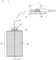
- FIG. 1 is a plan view and a partial enlarged sectional view of an electrode according to a first embodiment.
- an electrode current collector 110 includes an electrode main body 101 having an electrode mixture layer 120 formed thereon and an electrode tab 130, which is a non-coating portion extending from an outer periphery of the electrode mixture layer 120.
- An adhesive coating portion 140 is added to a portion of an upper surface of the electrode tab 130 at a position adjacent to the electrode mixture layer 120.
- the force of adhesion between a separator and the electrode may be increased through the adhesive coating portion 140, whereby the force of coupling between the electrode and the separator may be increased and the electrode and the separator may be integrally coupled to each other.
- Internal short circuit may occur between a positive electrode and a negative electrode as follows: internal short circuit may occur due to contact between a positive electrode mixture layer and a negative electrode mixture layer, contact between the positive electrode mixture layer and a negative electrode current collector, contact between a positive electrode current collector and the negative electrode mixture layer, or contact between the positive electrode current collector and the negative electrode current collector.
- the positive electrode current collector positive electrode tab
- the negative electrode mixture layer come into contact with each other, the largest amount of heat is generated.
- the adhesive coating portion 140 When the adhesive coating portion 140 is added to the upper surface of the electrode tab, as shown in FIG. 1 , it is possible to secure the force of adhesion between the electrode tab and the separator. In addition, even when the temperature of the adhesive coating portion 140 reaches a temperature at which an adhesive function of the adhesive coating portion is lost, it is possible to prevent contact between the positive electrode tab and the negative electrode mixture layer, since the adhesive coating portion 140 is added to an outer surface of the electrode tab.
- the electrode tab 130 may be connected to an electrode lead and may extend outwards from a battery case so as to be used as an electrode terminal.
- the adhesive coating portion 140 is added to a portion of the electrode tab 130 adjacent to the electrode mixture layer 120; however, a non-coating portion is exposed from an end of the electrode tab 130 opposite the electrode mixture layer 120 such that the end of the electrode tab is coupled to the electrode lead.
- the thickness H2 of the adhesive coating portion 140 may be equal to or greater than the thickness H1 of the electrode mixture layer 120 such that the adhesive coating portion and the separator can be easily attached to each other.
- lamination may be possible even though the thickness H2 of the adhesive coating portion is less than the thickness H1 of the electrode mixture layer.
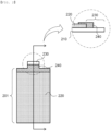
- FIG. 2 is a plan view and a partial enlarged sectional view of an electrode according to a second embodiment.
- an electrode current collector 210 includes an electrode main body 201 having an electrode mixture layer 220 formed thereon and an electrode tab 230, which is a non-coating portion extending from an outer periphery of the electrode mixture layer 220.
- the electrode tab 230 is formed as the result of a portion of an outer periphery of one side of the electrode main body 201 further extending outwards, and is coupled to an electrode lead.
- An adhesive coating portion 240 is added to an upper surface of the electrode tab 230 and an upper surface of an outer periphery of one side of the electrode mixture layer 220 adjacent to the electrode tab 230.
- the adhesive coating portion is added along the outer periphery of one side of the electrode mixture layer, as described above, it is possible to more widely secure the adhesive interface between a separator and the adhesive coating portion.
- the adhesive coating portion 240 is added to only the remaining portion of the electrode tab excluding an outer end thereof, and the adhesive coating portion 240 is not applied to the end of the electrode tab 230 that functions as the electrode tab.
- the end of the electrode tab constitutes a weld portion for coupling with the electrode lead.
- the area of a negative electrode is generally formed so as to be greater than the area of a positive electrode.
- lamination may be performed in the state in which the negative electrode is not present on the surface opposite the positive electrode.
- an end region of the negative electrode may be overcharged, whereby lithium precipitation may occur, and therefore lithium dendrites may be formed.
- the lithium dendrites may grow toward the positive electrode through the separator, whereby internal short circuit may occur.
- the adhesive coating portion is formed on the positive electrode so as to further extend in a direction from the outer periphery of the positive electrode mixture layer to a positive electrode tab. In this case, it is possible to prevent the occurrence of short circuit due to contact between lithium dendrites growing toward the positive electrode and the positive electrode tab.
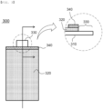
- FIG. 3 is a plan view and a partial enlarged sectional view of an electrode according to a third embodiment.
- the electrode 300 is identical to the electrodes shown in FIGs. 1 and 2 in terms of the structures of an electrode mixture layer 320 formed on an electrode current collector 310 and an electrode tab 330.
- An adhesive coating portion 340 is formed on only an upper surface of the electrode mixture layer 320. Specifically, the adhesive coating portion is formed on only an upper surface of an outer periphery of one side of the electrode mixture layer 320 adjacent to the electrode tab 330.
- a separator and the electrode may be stably coupled to each other via the adhesive coating portion at the outer periphery of one side of the electrode mixture layer adjacent to the electrode tab.
- FIG. 4 is a plan view and a partial enlarged sectional view of an electrode according to a fourth embodiment.
- the electrode 400 is identical to the electrodes shown in FIGs. 1 to 3 in terms of the structures of an electrode mixture layer 420 formed on an electrode current collector 410 and an electrode tab 430.
- An adhesive coating portion 440 is formed on an upper surface of an outer periphery of the electrode mixture layer 420 opposite an outer periphery of one side of the electrode mixture layer at which the electrode tab 430 is formed.
- FIG. 5 is a plan view and a partial enlarged sectional view of an electrode according to a fifth embodiment.
- the electrode 500 is identical to the electrodes shown in FIGs. 1 to 4 in terms of the structures of an electrode mixture layer 520 formed on an electrode current collector 510 and an electrode tab 530.
- An adhesive coating portion 540 is formed on an upper surface of the electrode tab 530, an upper surface of an outer periphery of one side of the electrode mixture layer 520 adjacent to the electrode tab 530, and an upper surface of an outer periphery of the electrode mixture layer 520 opposite the outer periphery of the one side of the electrode mixture layer 520.
- FIG. 5 shows that the adhesive coating portion 540 of the electrode 500 is formed on outer peripheries of opposite sides of the electrode mixture layer in an overall width direction W thereof.
- the adhesive coating portion may be formed on outer peripheries of opposite sides of the electrode mixture layer in an overall length direction L thereof.
- the adhesive coating portion may be formed on the outer peripheries of the opposite sides of the electrode mixture layer in the overall length direction L thereof and an upper surface of the electrode tab.
- FIG. 6 is a plan view and a partial enlarged sectional view of an electrode according to a sixth embodiment.
- the electrode 600 is identical to the electrodes shown in FIGs. 1 to 5 in terms of the structures of an electrode mixture layer 620 formed on an electrode current collector and an electrode tab 630.
- An adhesive coating portion 640 is formed along the entirety of an outer periphery of an upper surface of the electrode mixture layer 620, which has a rectangular shape when viewed in plan. Additionally, the adhesive coating portion may be formed on the entirety of the outer periphery of the upper surface of the electrode mixture layer and an upper surface of the electrode tab 630.
- the adhesive interface between the adhesive coating portion 640 and a separator is widely formed, whereby the separator and the electrode may be stably coupled to each other.
- FIG. 7 is a partial perspective view of electrodes according to a seventh embodiment and an eighth embodiment.
- the electrode 700 is an electrode according to a first embodiment
- the electrode 800 is an electrode according to an eighth embodiment.
- Each of the electrodes shown in FIG. 7 includes an inclined portion 722 or 822 formed at a portion of an outer periphery of an electrode mixture layer 720 or 820 to which an electrode tab 730 or 830 is connected, wherein an outer surface of the inclined portion in a thickness direction thereof is inclined.
- An adhesive coating portion 740 is shown as being applied to only a portion of an upper surface of the inclined portion 722 of the electrode mixture layer 720 adjacent to the electrode tab 730. Unlike this, the adhesive coating portion may be added so as to extend up to an upper part of the electrode tab 730.
- the adhesive coating portion 840 of FIG. 7 is shown as being applied along an outer periphery of an upper surface of the inclined portion 822 of the electrode mixture layer 820 adjacent to the electrode tab 830. Unlike this, the adhesive coating portion 840 may be added so as to extend up to an upper part of the electrode tab 830.
- the thickness of the adhesive coating portion 740 or 840 added to the inclined portion 722 or 822 is gradually increased toward the outer periphery of the electrode mixture layer 720 or 820, and the maximum thickness of the adhesive coating portion 740 or 840 is formed so as to be equal to or greater than the thickness of the electrode mixture layer 720 or 820.
- the separator and the adhesive coating portion may be attached to each other in tight contact with each other.
- the maximum thickness of the adhesive coating portion 740 or 840 may be formed so as to be less than the thickness of the electrode mixture layer 720 or 820. Even in this case, the adhesive coating portion and the separator may be attached to each other through lamination.
- the adhesive coating portion may be added to at least one of the first surface and the second surface of the electrode current collector, and a separator may be attached to the adhesive coating portion on at least one of the first surface and the second surface of the electrode current collector, to which the adhesive coating portion is added.
- the electrode may be a positive electrode and/or a negative electrode, wherein the separator may be attached to a portion of an outer surface of the positive electrode to which the adhesive coating portion is added, the separator may be attached to a portion of an outer surface of the negative electrode to which the adhesive coating portion is added, or the separator may be attached to the portion of the outer surface of each of the positive electrode and the negative electrode to which the adhesive coating portion is added.
- the adhesive coating portion includes an adhesive.
- the adhesive may include a polymer material having a glass transition temperature (Tg) of 100°C or lower.
- Tg glass transition temperature
- the adhesive may be polyacrylate, polyacrylic acid, polymethacrylate, polymethyl methacrylate, polyvinyl alcohol, polyvinyl chloride, polyvinylidene fluoride, polyvinylidene fluoridehexafluoropropylene, polyethylene, polypropylene, polybutadiene, polyisoprene, styrene butadiene rubber, polyvinyl acetate, polyester, polysiloxane, polydimethylsiloxane, polyethylene terephthalate, polyethylene oxide, polypropylene oxide, polyacrylonitrile, polyvinyl acetal, polyvinyl propionate, ethyl cellulose, carboxymethyl cellulose, polyperfluoropropylene, natural rubber, or a derivative or copolymer thereof.
- the adhesive coating portion is a portion adhered to the separator.
- the adhesive included in the adhesive coating portion may be a non-electric conductive adhesive.
- the kind of the adhesive included in the adhesive coating portion and the composition ratio of the adhesive may be adjusted to adjust the glass transition temperature of the adhesive.
- the area of the adhesive coating portion may be adjusted, and time and temperature necessary to attach the separator to the adhesive coating portion may also be adjusted. It is possible to adjust adhesive force of the adhesive coating portion by adjusting the composition, area, pressing time, and pressing temperature of the adhesive coating portion, as described above.
- FIG. 8 is a view showing a process of manufacturing an electrode for a lithium secondary battery.
- An electrode mixture layer 220 is formed on at least one surface of an electrode current collector 210. Unlike what is shown in FIG. 8 , however, the electrode mixture layer 220 may be formed on each of opposite surfaces of the electrode current collector 210. In addition, the electrode mixture layer 220 may be formed so as to have a uniform thickness, or the electrode mixture layer may include an inclined portion formed at an outer periphery thereof adjacent to an electrode tab 230 such that an outer surface of the inclined portion in a thickness direction thereof is inclined, as in the electrode mixture layers 720 and 820 shown in FIG. 7 .
- An adhesive coating portion 240 is added to a portion of an upper surface of the electrode tab 230 and an upper surface of an outer periphery of one side of the electrode mixture layer 220 adjacent to the electrode tab 230.
- the adhesive coating portion 240 may be added to only the remaining portion of the electrode tab excluding an outer end thereof, and the outer end of the electrode tab to which the adhesive coating portion is not added may be coupled to an electrode lead, whereby electrical connection may be achieved.
- a separator 910 is disposed above the electrode mixture layer 220 and on the adhesive coating portion 240.
- a left end of the separator 910 extends farther than the electrode mixture layer 220.
- a right end of the separator 910 extends to an outer end of the adhesive coating portion 240 or extends farther than the outer end of the adhesive coating portion 240.
- the electrode and the separator are pressed using a pair of pressing rolls 900 disposed above and under the electrode and the separator, respectively, such that the electrode and the separator are attached to each other.
- the adhesive coating portion includes a non-electric conductive adhesive made of a polymer material having a glass transition temperature (Tg) of 100°C or lower. Pressing may be performed in the state in which the pressing rolls 900 are heated such that the temperature of the pressing rolls is higher than the glass transition temperature of the non-electric conductive adhesive, whereby it is possible to secure the force of coupling between the adhesive coating portion 240 and the separator 910.
- Tg glass transition temperature
- the electrode manufactured using the above method forms an integrated structure together with the separator, and therefore it is possible to prevent separation of the separator from the electrode, thereby preventing bending or rolling of the separator. In addition, it is possible to secure insulation between a positive electrode and a negative electrode.
- the electrode manufactured as described above may be used as an electrode for a lithium secondary battery and may constitute a stacked type electrode assembly, a stacked and folded type electrode assembly, a laminated and stacked type electrode assembly, or a jelly-roll type electrode assembly.
- the above electrode may be received in a battery case to constitute a unit battery, and a battery module or a battery pack including the unit battery may be provided.
Landscapes
- Chemical & Material Sciences (AREA)
- Chemical Kinetics & Catalysis (AREA)
- Electrochemistry (AREA)
- General Chemical & Material Sciences (AREA)
- Engineering & Computer Science (AREA)
- Manufacturing & Machinery (AREA)
- Composite Materials (AREA)
- Materials Engineering (AREA)
- Battery Electrode And Active Subsutance (AREA)
- Connection Of Batteries Or Terminals (AREA)
- Secondary Cells (AREA)
Abstract
Description
- This application claims the benefit of priority to
Korean Patent Application No. 2021-0136064 filed on October 13, 2021 - The present invention relates to an electrode for a lithium secondary battery having an adhesive coating portion added thereto and a method of manufacturing the same. More particularly, the present invention relates to an electrode for a lithium secondary battery having an adhesive coating portion added thereto such that the electrode is integrally formed with a separator, whereby bending of the separator is prevented, and a method of manufacturing the same.
- A lithium secondary battery, which can be repeatedly charged and discharged and which has high energy density, has attracted attention as a new energy source that has environmentally friendly characteristics, since the lithium secondary battery not only remarkably reduces the use of fossil fuels but also does not generate by-products as the result of the use of energy.
- The lithium secondary battery is manufactured by receiving an electrode assembly including a positive electrode, a negative electrode, and a separator in a battery case together with an electrolyte and sealing the battery case.
- An electrode including the positive electrode and the negative electrode may be manufactured by applying an electrode mixture layer to a portion of an electrode current collector excluding an electrode tab, and lamination may be performed in the state in which a separator is disposed at an outer surface of the electrode to manufacture an electrode assembly.
- If the force of adhesion between the electrode and the separator that are laminated is small, the separator may be separated from the electrode and may bent or rolled during transfer, stacking, and assembly of the electrode assembly.
- When the separator is bent, as described above, the positive electrode and the negative electrode come into contact with each other, whereby internal short circuit may occur.
- Meanwhile, when the lithium secondary battery is exposed to a high temperature or is abnormally operated, such as internal/external short circuit, overcharging, or overdischarging, the separator shrinks due to heat that is generated, whereby the positive electrode and the negative electrode come into direct contact with each other, and therefore a short circuit possibility is increased.
- Hence, various research to prevent internal short circuit, thereby securing safety of a battery cell, has been conducted.
- Patent Document 1 discloses a jelly-roll type electrode assembly, wherein a non-coating portion having no positive electrode mixture layer is provided on an outer surface of an electrode foil at the outermost circumferential portion of a positive electrode, an adhesive tape is adhered to a portion of the non-coating portion, and the adhesive tape is also adhered to a separator protruding farther upwards and downwards from the positive electrode.
- That is, in Patent Document 1, the adhesive tape is attached so as to connect a portion of the electrode foil and a portion of the separator to each other, whereby the position of the separator is fixed. In the above electrode assembly, a portion of a peripheral portion of the separator is fixed to the positive electrode, whereby it is possible to prevent internal short circuit due to shrinkage of the separator during heating.
- In Patent Document 1, however, a structure in which the non-coating portion is formed at the outermost side or the innermost side of the jelly-roll type electrode assembly is used, whereby application to a stacked type electrode assembly is difficult. In addition, since the separator cannot be fixed at a temperature equal to or higher than the melting point of the adhesive tape, whereby internal short circuit may occur due to contact between the positive electrode and a negative electrode.
- Therefore, there is a need to provide a method capable of preventing bending of a separator that may occur in a stacked type electrode assembly and preventing short circuit even though the separator shrinks.
- (Patent Document 1)
Japanese Registered Patent Publication No. 3932096 (2007.03.23 - The present invention has been made in view of the above problems, and it is an object of the present invention to provide an electrode for a lithium secondary battery having an adhesive coating portion added thereto such that the state in which the electrode and a separator is stably maintained during a process of manufacturing the electrode, whereby insulation between a positive electrode and a negative electrode is secured.
- It is another object of the present invention to provide a method of manufacturing the electrode for a lithium secondary battery.
- An electrode for a lithium secondary battery according to the present invention to accomplish the above objects includes an electrode mixture layer disposed on at least one of a first surface and a second surface of an electrode current collector, wherein the electrode current collector includes an electrode tab, which is a non-coating portion extending from an outer periphery of the electrode mixture layer as a portion other than a portion at which the electrode mixture layer is disposed, and an adhesive coating portion is disposed at at least a portion of an upper surface of the electrode tab and an upper surface of the electrode mixture layer.
- The adhesive coating portion may be disposed at at least a portion of the upper surface of the electrode tab.
- The adhesive coating portion may be disposed at an upper surface of an outer periphery of one side of the electrode mixture layer adjacent to the electrode tab.
- The adhesive coating portion may be disposed at an upper surface of an outer periphery of the electrode mixture layer opposite an outer periphery of one side of the electrode mixture layer at which the electrode tab is formed.
- The adhesive coating portion may be disposed at an upper surface of the electrode tab and an upper surface of an outer periphery of one side of the electrode mixture layer adjacent to the electrode tab.
- The adhesive coating portion may be disposed at an upper surface of the electrode tab, an upper surface of an outer periphery of one side of the electrode mixture layer adjacent to the electrode tab, and an upper surface of an outer periphery of the electrode mixture layer opposite the outer periphery of the one side of the electrode mixture layer.
- The adhesive coating portion may include a non-electric conductive adhesive.
- The non-electric conductive adhesive may be made of a polymer material having a glass transition temperature (Tg) of 100°C or lower.
- The adhesive coating portion may be disposed at at least one of the first surface and the second surface, and the electrode may include a separator attached to the adhesive coating portion on the at least one of the first surface and the second surface to which the adhesive coating portion is disposed.
- The present invention provides a method of manufacturing the electrode for a lithium secondary battery. Specifically, the method includes (a) forming an electrode mixture layer on at least one surface of an electrode current collector, (b) adding an adhesive coating portion to at least a portion of an upper surface of an electrode tab extending from an outer periphery of the electrode mixture layer and an upper surface of the electrode mixture layer, (c) disposing a separator on the electrode mixture layer and the adhesive coating portion of step (b), and (d) pressing the separator.
- Step (d) may include a heating process.
- The adhesive coating portion may be formed on at least one of a positive electrode and a negative electrode.
- The present invention provides an electrode assembly including the electrode for a lithium secondary battery, wherein the electrode assembly is a stacked type electrode assembly, a stacked and folded type electrode assembly, a laminated and stacked type electrode assembly, or a jelly-roll type electrode assembly.
- In addition, the present invention may provide various combinations of the above solving means.
- As is apparent from the above description, in an electrode for a lithium secondary battery according to the present invention, it is possible to secure the force of adhesion between the electrode and a separator by addition of an adhesive coating portion, whereby it is possible to prevent bending of the separator. Consequently, it is possible to secure insulation between a positive electrode and a negative electrode, and therefore it is possible to improve safety of a lithium secondary battery.
- In addition, it is possible to adjust the adhesive force by adjusting the glass transition temperature of an adhesive constituting the adhesive coating portion, the coating area, and temperature and/or time of a heating process.
- In addition, it is possible to inhibit shrinkage of the separator even at a high temperature, and therefore it is possible to prevent formation of a contact area between the positive electrode and the negative electrode when a battery cell is exposed to the high temperature.
- Meanwhile, when the adhesive coating portion is applied over an electrode mixture layer and an electrode tab, it is possible to prevent generation of lithium precipitates even though an end of an outer periphery of the negative electrode is shorter than an end of an outer periphery of the positive electrode.
-
-
FIG. 1 is a plan view and a partial enlarged sectional view of an electrode according to a first embodiment. -
FIG. 2 is a plan view and a partial enlarged sectional view of an electrode according to a second embodiment. -
FIG. 3 is a plan view and a partial enlarged sectional view of an electrode according to a third embodiment. -
FIG. 4 is a plan view and a partial enlarged sectional view of an electrode according to a fourth embodiment. -
FIG. 5 is a plan view and a partial enlarged sectional view of an electrode according to a fifth embodiment. -
FIG. 6 is a plan view and a partial enlarged sectional view of an electrode according to a sixth embodiment. -
FIG. 7 is a partial perspective view of electrodes according to a seventh embodiment and an eighth embodiment. -
FIG. 8 is a view showing a process of manufacturing an electrode for a lithium secondary battery. - Now, preferred embodiments of the present invention will be described in detail with reference to the accompanying drawings such that the preferred embodiments of the present invention can be easily implemented by a person having ordinary skill in the art to which the present invention pertains. In describing the principle of operation of the preferred embodiments of the present invention in detail, however, a detailed description of known functions and configurations incorporated herein will be omitted when the same may obscure the subject matter of the present invention.
- In addition, the same reference numbers will be used throughout the drawings to refer to parts that perform similar functions or operations. In the case in which one part is said to be connected to another part throughout the specification, not only may the one part be directly connected to the other part, but also, the one part may be indirectly connected to the other part via a further part. In addition, that a certain element is included does not mean that other elements are excluded, but means that such elements may be further included unless mentioned otherwise.
- In addition, a description to embody elements through limitation or addition may be applied to all inventions, unless particularly restricted, and does not limit a specific invention.
- Also, in the description of the invention and the claims of the present application, singular forms are intended to include plural forms unless mentioned otherwise.
- Also, in the description of the invention and the claims of the present application, "or" includes "and" unless mentioned otherwise. Therefore, "including A or B" means three cases, namely, the case including A, the case including B, and the case including A and B.
- Hereinafter, embodiments of the present invention will be described in detail with reference to the accompanying drawings.
- An electrode according to the present invention may be configured to have a structure in which an electrode tab protrudes from an outer periphery of one side of an electrode current collector having a rectangular shape when viewed in plan and in which an electrode mixture layer is formed on the electrode current collector. In addition, the electrode according to the present invention may be configured to have a structure in which an electrode tab may be attached to a long sheet type electrode current collector and in which an electrode mixture layer is formed on the electrode current collector.
- The electrode mixture layer is formed on at least one of a first surface, which is an upper surface, and a second surface, which is a lower surface, of the electrode current collector.
- The electrode current collector includes an electrode tab, which is a non-coating portion extending from an outer periphery of the electrode mixture layer as a portion other than a portion at which the electrode mixture layer is formed, and an adhesive coating portion is added to at least a portion of an upper surface of the electrode tab and an upper surface of the electrode mixture layer. The non-coating portion means a portion at which the electrode mixture layer is not formed.
- The adhesive coating portion is made of a material that allows a separator to be adhered thereto while having an insulation property. Even when the temperature of the adhesive coating portion reaches a temperature at which an adhesive function of the adhesive coating portion is lost and the separator shrinks, therefore, the adhesive coating portion remains added to the electrode, whereby it is possible to prevent contact with another electrode.
-
FIG. 1 is a plan view and a partial enlarged sectional view of an electrode according to a first embodiment. - Referring to
FIG. 1 , an electrodecurrent collector 110 includes an electrodemain body 101 having anelectrode mixture layer 120 formed thereon and anelectrode tab 130, which is a non-coating portion extending from an outer periphery of theelectrode mixture layer 120. - An
adhesive coating portion 140 is added to a portion of an upper surface of theelectrode tab 130 at a position adjacent to theelectrode mixture layer 120. - The force of adhesion between a separator and the electrode may be increased through the
adhesive coating portion 140, whereby the force of coupling between the electrode and the separator may be increased and the electrode and the separator may be integrally coupled to each other. - Internal short circuit may occur between a positive electrode and a negative electrode as follows: internal short circuit may occur due to contact between a positive electrode mixture layer and a negative electrode mixture layer, contact between the positive electrode mixture layer and a negative electrode current collector, contact between a positive electrode current collector and the negative electrode mixture layer, or contact between the positive electrode current collector and the negative electrode current collector. When the positive electrode current collector (positive electrode tab) and the negative electrode mixture layer come into contact with each other, the largest amount of heat is generated.
- When the
adhesive coating portion 140 is added to the upper surface of the electrode tab, as shown inFIG. 1 , it is possible to secure the force of adhesion between the electrode tab and the separator. In addition, even when the temperature of theadhesive coating portion 140 reaches a temperature at which an adhesive function of the adhesive coating portion is lost, it is possible to prevent contact between the positive electrode tab and the negative electrode mixture layer, since theadhesive coating portion 140 is added to an outer surface of the electrode tab. - The
electrode tab 130 may be connected to an electrode lead and may extend outwards from a battery case so as to be used as an electrode terminal. - Consequently, the
adhesive coating portion 140 is added to a portion of theelectrode tab 130 adjacent to theelectrode mixture layer 120; however, a non-coating portion is exposed from an end of theelectrode tab 130 opposite theelectrode mixture layer 120 such that the end of the electrode tab is coupled to the electrode lead. - The thickness H2 of the
adhesive coating portion 140 may be equal to or greater than the thickness H1 of theelectrode mixture layer 120 such that the adhesive coating portion and the separator can be easily attached to each other. - Alternatively, when the shape of a pressing roll configured to perform lamination is changed or a pressing method is adjusted, lamination may be possible even though the thickness H2 of the adhesive coating portion is less than the thickness H1 of the electrode mixture layer.
-
FIG. 2 is a plan view and a partial enlarged sectional view of an electrode according to a second embodiment. - Referring to
FIG. 2 , an electrodecurrent collector 210 includes an electrodemain body 201 having anelectrode mixture layer 220 formed thereon and anelectrode tab 230, which is a non-coating portion extending from an outer periphery of theelectrode mixture layer 220. - The
electrode tab 230 is formed as the result of a portion of an outer periphery of one side of the electrodemain body 201 further extending outwards, and is coupled to an electrode lead. - An
adhesive coating portion 240 is added to an upper surface of theelectrode tab 230 and an upper surface of an outer periphery of one side of theelectrode mixture layer 220 adjacent to theelectrode tab 230. When the adhesive coating portion is added along the outer periphery of one side of the electrode mixture layer, as described above, it is possible to more widely secure the adhesive interface between a separator and the adhesive coating portion. - The
adhesive coating portion 240 is added to only the remaining portion of the electrode tab excluding an outer end thereof, and theadhesive coating portion 240 is not applied to the end of theelectrode tab 230 that functions as the electrode tab. The end of the electrode tab constitutes a weld portion for coupling with the electrode lead. - Meanwhile, when an electrode assembly is manufactured, the area of a negative electrode is generally formed so as to be greater than the area of a positive electrode. When the positive electrode and the negative electrode are misaligned with each other during a lamination process, lamination may be performed in the state in which the negative electrode is not present on the surface opposite the positive electrode.
- In this case, an end region of the negative electrode may be overcharged, whereby lithium precipitation may occur, and therefore lithium dendrites may be formed. The lithium dendrites may grow toward the positive electrode through the separator, whereby internal short circuit may occur. In the present invention, as shown in
FIG. 2 , the adhesive coating portion is formed on the positive electrode so as to further extend in a direction from the outer periphery of the positive electrode mixture layer to a positive electrode tab. In this case, it is possible to prevent the occurrence of short circuit due to contact between lithium dendrites growing toward the positive electrode and the positive electrode tab. -
FIG. 3 is a plan view and a partial enlarged sectional view of an electrode according to a third embodiment. - Referring to
FIG. 3 , theelectrode 300 is identical to the electrodes shown inFIGs. 1 and2 in terms of the structures of anelectrode mixture layer 320 formed on an electrodecurrent collector 310 and anelectrode tab 330. - An
adhesive coating portion 340 is formed on only an upper surface of theelectrode mixture layer 320. Specifically, the adhesive coating portion is formed on only an upper surface of an outer periphery of one side of theelectrode mixture layer 320 adjacent to theelectrode tab 330. - Consequently, a separator and the electrode may be stably coupled to each other via the adhesive coating portion at the outer periphery of one side of the electrode mixture layer adjacent to the electrode tab.
-
FIG. 4 is a plan view and a partial enlarged sectional view of an electrode according to a fourth embodiment. - Referring to
FIG. 4 , theelectrode 400 is identical to the electrodes shown inFIGs. 1 to 3 in terms of the structures of anelectrode mixture layer 420 formed on an electrodecurrent collector 410 and anelectrode tab 430. - An
adhesive coating portion 440 is formed on an upper surface of an outer periphery of theelectrode mixture layer 420 opposite an outer periphery of one side of the electrode mixture layer at which theelectrode tab 430 is formed. -
FIG. 5 is a plan view and a partial enlarged sectional view of an electrode according to a fifth embodiment. - Referring to
FIG. 5 , theelectrode 500 is identical to the electrodes shown inFIGs. 1 to 4 in terms of the structures of anelectrode mixture layer 520 formed on an electrodecurrent collector 510 and anelectrode tab 530. - An
adhesive coating portion 540 is formed on an upper surface of theelectrode tab 530, an upper surface of an outer periphery of one side of theelectrode mixture layer 520 adjacent to theelectrode tab 530, and an upper surface of an outer periphery of theelectrode mixture layer 520 opposite the outer periphery of the one side of theelectrode mixture layer 520. -
FIG. 5 shows that theadhesive coating portion 540 of theelectrode 500 is formed on outer peripheries of opposite sides of the electrode mixture layer in an overall width direction W thereof. Alternatively, the adhesive coating portion may be formed on outer peripheries of opposite sides of the electrode mixture layer in an overall length direction L thereof. Also, in the present invention, the adhesive coating portion may be formed on the outer peripheries of the opposite sides of the electrode mixture layer in the overall length direction L thereof and an upper surface of the electrode tab. -
FIG. 6 is a plan view and a partial enlarged sectional view of an electrode according to a sixth embodiment. - Referring to
FIG. 6 , theelectrode 600 is identical to the electrodes shown inFIGs. 1 to 5 in terms of the structures of anelectrode mixture layer 620 formed on an electrode current collector and anelectrode tab 630. - An
adhesive coating portion 640 is formed along the entirety of an outer periphery of an upper surface of theelectrode mixture layer 620, which has a rectangular shape when viewed in plan. Additionally, the adhesive coating portion may be formed on the entirety of the outer periphery of the upper surface of the electrode mixture layer and an upper surface of theelectrode tab 630. - In the
electrode 600 having the adhesive coating portion, formed as described above, added thereto, the adhesive interface between theadhesive coating portion 640 and a separator is widely formed, whereby the separator and the electrode may be stably coupled to each other. -
FIG. 7 is a partial perspective view of electrodes according to a seventh embodiment and an eighth embodiment. - Referring to
FIG. 7 , theelectrode 700 is an electrode according to a first embodiment, and theelectrode 800 is an electrode according to an eighth embodiment. - Each of the electrodes shown in
FIG. 7 includes aninclined portion electrode mixture layer electrode tab adhesive coating portion 740 is shown as being applied to only a portion of an upper surface of theinclined portion 722 of theelectrode mixture layer 720 adjacent to theelectrode tab 730. Unlike this, the adhesive coating portion may be added so as to extend up to an upper part of theelectrode tab 730. - Consequently, it is possible to secure the force of adhesion between the separator and the electrode through the adhesive coating portion at a region of the electrode adjacent to the electrode tab, at which a largest amount of heat is generated.
- The
adhesive coating portion 840 ofFIG. 7 is shown as being applied along an outer periphery of an upper surface of theinclined portion 822 of theelectrode mixture layer 820 adjacent to theelectrode tab 830. Unlike this, theadhesive coating portion 840 may be added so as to extend up to an upper part of theelectrode tab 830. - Consequently, it is possible to secure the force of adhesion between the separator and the electrode through the adhesive coating portion at the outer periphery of the
electrode mixture layer 820 adjacent to theelectrode tab 830. - The thickness of the
adhesive coating portion inclined portion electrode mixture layer adhesive coating portion electrode mixture layer - Alternatively, the maximum thickness of the
adhesive coating portion electrode mixture layer - In each of the electrodes according to the first to eighth embodiments of the present invention, the adhesive coating portion may be added to at least one of the first surface and the second surface of the electrode current collector, and a separator may be attached to the adhesive coating portion on at least one of the first surface and the second surface of the electrode current collector, to which the adhesive coating portion is added.
- The electrode may be a positive electrode and/or a negative electrode, wherein the separator may be attached to a portion of an outer surface of the positive electrode to which the adhesive coating portion is added, the separator may be attached to a portion of an outer surface of the negative electrode to which the adhesive coating portion is added, or the separator may be attached to the portion of the outer surface of each of the positive electrode and the negative electrode to which the adhesive coating portion is added.
- As a result, an integrated structure in which the electrode and the separator are coupled to each other via the adhesive coating portion is formed, and therefore it is possible to prevent separation of the separator from the electrode, thereby preventing bending or rolling of the separator.
- The adhesive coating portion includes an adhesive.
- The adhesive may include a polymer material having a glass transition temperature (Tg) of 100°C or lower. For example, the adhesive may be polyacrylate, polyacrylic acid, polymethacrylate, polymethyl methacrylate, polyvinyl alcohol, polyvinyl chloride, polyvinylidene fluoride, polyvinylidene fluoridehexafluoropropylene, polyethylene, polypropylene, polybutadiene, polyisoprene, styrene butadiene rubber, polyvinyl acetate, polyester, polysiloxane, polydimethylsiloxane, polyethylene terephthalate, polyethylene oxide, polypropylene oxide, polyacrylonitrile, polyvinyl acetal, polyvinyl propionate, ethyl cellulose, carboxymethyl cellulose, polyperfluoropropylene, natural rubber, or a derivative or copolymer thereof.
- The adhesive coating portion is a portion adhered to the separator. In order to secure insulation between different electrodes, the adhesive included in the adhesive coating portion may be a non-electric conductive adhesive.
- In the present invention, the kind of the adhesive included in the adhesive coating portion and the composition ratio of the adhesive may be adjusted to adjust the glass transition temperature of the adhesive. In addition, the area of the adhesive coating portion may be adjusted, and time and temperature necessary to attach the separator to the adhesive coating portion may also be adjusted. It is possible to adjust adhesive force of the adhesive coating portion by adjusting the composition, area, pressing time, and pressing temperature of the adhesive coating portion, as described above.
-
FIG. 8 is a view showing a process of manufacturing an electrode for a lithium secondary battery. - An
electrode mixture layer 220 is formed on at least one surface of an electrodecurrent collector 210. Unlike what is shown inFIG. 8 , however, theelectrode mixture layer 220 may be formed on each of opposite surfaces of the electrodecurrent collector 210. In addition, theelectrode mixture layer 220 may be formed so as to have a uniform thickness, or the electrode mixture layer may include an inclined portion formed at an outer periphery thereof adjacent to anelectrode tab 230 such that an outer surface of the inclined portion in a thickness direction thereof is inclined, as in the electrode mixture layers 720 and 820 shown inFIG. 7 . - An
adhesive coating portion 240 is added to a portion of an upper surface of theelectrode tab 230 and an upper surface of an outer periphery of one side of theelectrode mixture layer 220 adjacent to theelectrode tab 230. - The
adhesive coating portion 240 may be added to only the remaining portion of the electrode tab excluding an outer end thereof, and the outer end of the electrode tab to which the adhesive coating portion is not added may be coupled to an electrode lead, whereby electrical connection may be achieved. - A
separator 910 is disposed above theelectrode mixture layer 220 and on theadhesive coating portion 240. A left end of theseparator 910 extends farther than theelectrode mixture layer 220. A right end of theseparator 910 extends to an outer end of theadhesive coating portion 240 or extends farther than the outer end of theadhesive coating portion 240. - In the state in which the electrode and the separator are disposed so as to overlap each other, as described above, the electrode and the separator are pressed using a pair of
pressing rolls 900 disposed above and under the electrode and the separator, respectively, such that the electrode and the separator are attached to each other. - The adhesive coating portion includes a non-electric conductive adhesive made of a polymer material having a glass transition temperature (Tg) of 100°C or lower. Pressing may be performed in the state in which the
pressing rolls 900 are heated such that the temperature of the pressing rolls is higher than the glass transition temperature of the non-electric conductive adhesive, whereby it is possible to secure the force of coupling between theadhesive coating portion 240 and theseparator 910. - The electrode manufactured using the above method forms an integrated structure together with the separator, and therefore it is possible to prevent separation of the separator from the electrode, thereby preventing bending or rolling of the separator. In addition, it is possible to secure insulation between a positive electrode and a negative electrode.
- The electrode manufactured as described above may be used as an electrode for a lithium secondary battery and may constitute a stacked type electrode assembly, a stacked and folded type electrode assembly, a laminated and stacked type electrode assembly, or a jelly-roll type electrode assembly.
- In addition, the above electrode may be received in a battery case to constitute a unit battery, and a battery module or a battery pack including the unit battery may be provided.
- Those skilled in the art to which the present invention pertains will appreciate that various applications and modifications are possible within the category of the present invention based on the above description.
-
- 101, 201: Electrode main bodies
- 110, 210, 310, 410, 510: Electrode current collectors
- 120, 220, 320, 420, 520, 620, 720, 820: Electrode mixture layers
- 130, 230, 330, 430, 530, 630, 730, 830: Electrode tabs
- 140, 240, 340, 440, 540, 640, 740, 840: Adhesive coating portions
- 722, 822: Inclined portions
- 300, 400, 500, 600, 700, 800: Electrodes
- 900: Pressing roll
- 910: Separator
- Hl: Thickness of electrode mixture layer
- H2: Thickness of adhesive coating portion
- L: Overall length direction
- W: Overall width direction
Claims (13)
- An electrode for a lithium secondary battery, the electrode comprising:an electrode mixture layer disposed on at least one of a first surface and a second surface of an electrode current collector, whereinthe electrode current collector comprises an electrode tab, which is a non-coating portion extending from an outer periphery of the electrode mixture layer as a portion other than a portion at which the electrode mixture layer is disposed, andan adhesive coating portion is disposed at at least a portion of an upper surface of the electrode tab and an upper surface of the electrode mixture layer.
- The electrode according to claim 1, wherein the adhesive coating portion is disposed at at least a portion of the upper surface of the electrode tab.
- The electrode according to claim 1, wherein the adhesive coating portion is disposed at an upper surface of an outer periphery of one side of the electrode mixture layer adjacent to the electrode tab.
- The electrode according to claim 1, wherein the adhesive coating portion is disposed at an upper surface of an outer periphery of the electrode mixture layer opposite an outer periphery of one side of the electrode mixture layer at which the electrode tab is formed.
- The electrode according to claim 1, wherein the adhesive coating portion is disposed at an upper surface of the electrode tab and an upper surface of an outer periphery of one side of the electrode mixture layer adjacent to the electrode tab.
- The electrode according to claim 1, wherein the adhesive coating portion is disposed at an upper surface of the electrode tab, an upper surface of an outer periphery of one side of the electrode mixture layer adjacent to the electrode tab, and an upper surface of an outer periphery of the electrode mixture layer opposite the outer periphery of the one side of the electrode mixture layer.
- The electrode according to claim 1, wherein the adhesive coating portion comprises a non-electric conductive adhesive.
- The electrode according to claim 7, wherein the non-electric conductive adhesive is made of a polymer material having a glass transition temperature (Tg) of 100°C or lower.
- The electrode according to claim 1, whereinthe adhesive coating portion is disposed at at least one of the first surface and the second surface, andthe electrode comprises a separator attached to the adhesive coating portion on the at least one of the first surface and the second surface to which the adhesive coating portion is disposed.
- A method of manufacturing the electrode according to any one of claims 1 to 9, the method comprising:(a) forming an electrode mixture layer on at least one surface of an electrode current collector;(b) adding an adhesive coating portion to at least a portion of an upper surface of an electrode tab extending from an outer periphery of the electrode mixture layer and an upper surface of the electrode mixture layer;(c) disposing a separator on the electrode mixture layer and the adhesive coating portion of step (b); and(d) pressing the separator.
- The method according to claim 10, wherein step (d) comprises a heating process.
- The method according to claim 10, wherein the adhesive coating portion is formed on at least one of a positive electrode and a negative electrode.
- An electrode assembly comprising the electrode according to any one of claims 1 to 9, wherein the electrode assembly is a stacked type electrode assembly, a stacked and folded type electrode assembly, a laminated and stacked type electrode assembly, or a jelly-roll type electrode assembly.
Applications Claiming Priority (2)
| Application Number | Priority Date | Filing Date | Title |
|---|---|---|---|
| KR1020210136064A KR102951733B1 (en) | 2021-10-13 | 2021-10-13 | Electrode for Lithium Secondary Battery with Adhesive Coating and Method for Manufacturing the Same |
| PCT/KR2022/015466 WO2023063734A1 (en) | 2021-10-13 | 2022-10-13 | Electrode for lithium secondary battery to which adhesive coating part is added, and method for manufacturing same |
Publications (3)
| Publication Number | Publication Date |
|---|---|
| EP4250431A1 true EP4250431A1 (en) | 2023-09-27 |
| EP4250431A4 EP4250431A4 (en) | 2025-04-09 |
| EP4250431B1 EP4250431B1 (en) | 2026-04-01 |
Family
ID=85987546
Family Applications (1)
| Application Number | Title | Priority Date | Filing Date |
|---|---|---|---|
| EP22881361.4A Active EP4250431B1 (en) | 2021-10-13 | 2022-10-13 | Electrode for lithium secondary battery having adhesive coating portion added thereto and method of manufacturing the same |
Country Status (6)
| Country | Link |
|---|---|
| US (1) | US20230411597A1 (en) |
| EP (1) | EP4250431B1 (en) |
| JP (1) | JP7841759B2 (en) |
| KR (1) | KR102951733B1 (en) |
| CN (1) | CN116670916A (en) |
| WO (1) | WO2023063734A1 (en) |
Families Citing this family (2)
| Publication number | Priority date | Publication date | Assignee | Title |
|---|---|---|---|---|
| CN121336316A (en) * | 2023-06-08 | 2026-01-13 | 株式会社Lg化学 | Electrode assemblies and electrochemical elements including them |
| EP4726821A1 (en) * | 2024-10-11 | 2026-04-15 | LG Energy Solution, Ltd. | A system and a method for manufacturing a secondary battery assembly |
Family Cites Families (20)
| Publication number | Priority date | Publication date | Assignee | Title |
|---|---|---|---|---|
| JP3932096B2 (en) | 2001-12-04 | 2007-06-20 | 日立マクセル株式会社 | Non-aqueous secondary battery |
| KR100601555B1 (en) * | 2004-06-14 | 2006-07-19 | 삼성에스디아이 주식회사 | Wound electrode assembly and lithium secondary battery using same |
| US20060216609A1 (en) * | 2005-03-23 | 2006-09-28 | Hitachi Maxell, Ltd. | Non-aqueous electrolyte battery and method for producing the same |
| JP5427046B2 (en) * | 2010-01-14 | 2014-02-26 | 日立マクセル株式会社 | Non-aqueous electrolyte battery and manufacturing method thereof |
| JP5419811B2 (en) * | 2010-06-30 | 2014-02-19 | 日立マクセル株式会社 | Non-aqueous secondary battery |
| KR101161147B1 (en) * | 2010-07-08 | 2012-06-29 | 주식회사 엘지화학 | Device for Attachment of Electrode Tape |
| JP5701688B2 (en) * | 2011-01-31 | 2015-04-15 | 三洋電機株式会社 | Multilayer battery and method for manufacturing the same |
| JP2012221913A (en) | 2011-04-14 | 2012-11-12 | Nissan Motor Co Ltd | Method for manufacturing electrodes and laser cutting device |
| CN104755575B (en) * | 2012-11-05 | 2018-02-09 | 日东电工株式会社 | Adhesive tape for electrochemical device |
| KR101586530B1 (en) * | 2013-03-11 | 2016-01-21 | 주식회사 엘지화학 | Cathode comprising insulating layer on cathode tab and secondary battery comprising the same |
| KR20150057716A (en) * | 2013-11-20 | 2015-05-28 | 삼성에스디아이 주식회사 | Rechargeable battery |
| JP6413254B2 (en) * | 2014-02-13 | 2018-10-31 | 日産自動車株式会社 | Method for manufacturing electrode for secondary battery |
| JP6487669B2 (en) * | 2014-11-05 | 2019-03-20 | 昭和電工パッケージング株式会社 | Power storage device |
| JP6608596B2 (en) * | 2015-02-18 | 2019-11-20 | 日立オートモティブシステムズ株式会社 | Rectangular secondary battery and manufacturing method thereof |
| KR101977639B1 (en) * | 2016-02-16 | 2019-05-14 | 주식회사 엘지화학 | Electrode assembly and manufacturing method of thereof |
| JP6684000B2 (en) * | 2016-07-27 | 2020-04-22 | ビークルエナジージャパン株式会社 | Prismatic secondary battery |
| JP6930822B2 (en) * | 2016-08-31 | 2021-09-01 | 三洋電機株式会社 | Secondary battery electrodes and secondary batteries |
| JP7024723B2 (en) * | 2016-11-04 | 2022-02-24 | 株式会社Gsユアサ | A method for manufacturing an electrode for a power storage element, a power storage element, and an electrode for a power storage element. |
| JP7411347B2 (en) | 2019-03-19 | 2024-01-11 | Ntn株式会社 | Lubricating oil supply unit and bearing device |
| CN111916645B (en) * | 2020-07-01 | 2021-11-30 | 江苏塔菲尔新能源科技股份有限公司 | Pole piece, preparation method of pole piece and battery |
-
2021
- 2021-10-13 KR KR1020210136064A patent/KR102951733B1/en active Active
-
2022
- 2022-10-13 US US18/035,626 patent/US20230411597A1/en active Pending
- 2022-10-13 WO PCT/KR2022/015466 patent/WO2023063734A1/en not_active Ceased
- 2022-10-13 CN CN202280008597.7A patent/CN116670916A/en active Pending
- 2022-10-13 EP EP22881361.4A patent/EP4250431B1/en active Active
- 2022-10-13 JP JP2023534032A patent/JP7841759B2/en active Active
Also Published As
| Publication number | Publication date |
|---|---|
| KR20230052713A (en) | 2023-04-20 |
| WO2023063734A1 (en) | 2023-04-20 |
| JP2023551957A (en) | 2023-12-13 |
| EP4250431A4 (en) | 2025-04-09 |
| CN116670916A (en) | 2023-08-29 |
| US20230411597A1 (en) | 2023-12-21 |
| KR102951733B1 (en) | 2026-04-14 |
| EP4250431B1 (en) | 2026-04-01 |
| JP7841759B2 (en) | 2026-04-07 |
Similar Documents
| Publication | Publication Date | Title |
|---|---|---|
| CN110476273B (en) | Secondary battery and method of manufacturing the same | |
| EP2500972B1 (en) | Lithium secondary battery having multi-directional lead-tab structure | |
| CN1326281C (en) | Winding battery unit, winding method thereof and lithium secondary battery containing it | |
| JP6788107B2 (en) | Manufacturing method of electrode unit for battery cell and electrode unit | |
| EP2293367B1 (en) | Rechargeable secondary battery having improved safety against puncture and collapse | |
| EP3905417A1 (en) | Method for manufacturing electrode assembly, and electrode and secondary battery manufactured thereby | |
| US11349182B2 (en) | Electrode assembly | |
| US8889286B2 (en) | Secondary battery and method of fabricating secondary battery | |
| CN114583097A (en) | Pole piece, winding battery cell and battery | |
| CN112204800A (en) | All-solid-state battery using lithium metal as negative electrode | |
| EP4250431B1 (en) | Electrode for lithium secondary battery having adhesive coating portion added thereto and method of manufacturing the same | |
| EP4080644A1 (en) | Electrode assembly comprising disconnection prevention layer, and preparation method thereof | |
| JP7570755B2 (en) | Battery cell including electrode tab with stress relief portion formed thereon | |
| CN115398738A (en) | Electrode assembly having shape-fixing frame and lithium secondary battery including the same | |
| US12051774B2 (en) | Folding type electrode assembly and method of manufacturing the same | |
| KR20140022531A (en) | Electrode assembly and fabricating method of electrochemical cell containing the electrode assembly, electrochemical cell | |
| CN114600289B (en) | Electrode assembly and method for manufacturing the same | |
| EP4175054A1 (en) | Electrode having excellent weldability between electrode lead and electrode tab and manufacturing method therefor | |
| EP3944404A1 (en) | Secondary battery pouch | |
| KR102869017B1 (en) | Lithium ion secondary battery and manufacturing method of the same | |
| JP2000077055A (en) | Lithium secondary battery | |
| CN116868391A (en) | Electrode assembly and battery cell including the electrode assembly | |
| CN224067852U (en) | Battery cell and battery | |
| EP3598554B1 (en) | Electrode assembly and method for manufacturing electrode assembly | |
| EP4716002A1 (en) | Battery cell |
Legal Events
| Date | Code | Title | Description |
|---|---|---|---|
| STAA | Information on the status of an ep patent application or granted ep patent |
Free format text: STATUS: THE INTERNATIONAL PUBLICATION HAS BEEN MADE |
|
| PUAI | Public reference made under article 153(3) epc to a published international application that has entered the european phase |
Free format text: ORIGINAL CODE: 0009012 |
|
| STAA | Information on the status of an ep patent application or granted ep patent |
Free format text: STATUS: REQUEST FOR EXAMINATION WAS MADE |
|
| 17P | Request for examination filed |
Effective date: 20230620 |
|
| AK | Designated contracting states |
Kind code of ref document: A1 Designated state(s): AL AT BE BG CH CY CZ DE DK EE ES FI FR GB GR HR HU IE IS IT LI LT LU LV MC ME MK MT NL NO PL PT RO RS SE SI SK SM TR |
|
| DAV | Request for validation of the european patent (deleted) | ||
| DAX | Request for extension of the european patent (deleted) | ||
| A4 | Supplementary search report drawn up and despatched |
Effective date: 20250312 |
|
| RIC1 | Information provided on ipc code assigned before grant |
Ipc: H01M 4/04 20060101ALI20250306BHEP Ipc: H01M 10/052 20100101ALI20250306BHEP Ipc: H01M 10/058 20100101ALI20250306BHEP Ipc: H01M 50/46 20210101ALI20250306BHEP Ipc: H01M 50/531 20210101ALI20250306BHEP Ipc: H01M 10/42 20060101AFI20250306BHEP |
|
| GRAP | Despatch of communication of intention to grant a patent |
Free format text: ORIGINAL CODE: EPIDOSNIGR1 |
|
| STAA | Information on the status of an ep patent application or granted ep patent |
Free format text: STATUS: GRANT OF PATENT IS INTENDED |
|
| INTG | Intention to grant announced |
Effective date: 20251016 |
|
| P01 | Opt-out of the competence of the unified patent court (upc) registered |
Free format text: CASE NUMBER: UPC_APP_0012166_4250431/2025 Effective date: 20251105 |
|
| GRAS | Grant fee paid |
Free format text: ORIGINAL CODE: EPIDOSNIGR3 |
|
| GRAA | (expected) grant |
Free format text: ORIGINAL CODE: 0009210 |
|
| STAA | Information on the status of an ep patent application or granted ep patent |
Free format text: STATUS: THE PATENT HAS BEEN GRANTED |
|
| AK | Designated contracting states |
Kind code of ref document: B1 Designated state(s): AL AT BE BG CH CY CZ DE DK EE ES FI FR GB GR HR HU IE IS IT LI LT LU LV MC ME MK MT NL NO PL PT RO RS SE SI SK SM TR |
|
| REG | Reference to a national code |
Ref country code: CH Ref legal event code: F10 Free format text: ST27 STATUS EVENT CODE: U-0-0-F10-F00 (AS PROVIDED BY THE NATIONAL OFFICE) Effective date: 20260401 Ref country code: GB Ref legal event code: FG4D |
|
| REG | Reference to a national code |
Ref country code: IE Ref legal event code: FG4D |
|
| REG | Reference to a national code |
Ref country code: DE Ref legal event code: R096 Ref document number: 602022033730 Country of ref document: DE |