EP4250290A1 - Improved subband block based harmonic transposition - Google Patents
Improved subband block based harmonic transposition Download PDFInfo
- Publication number
- EP4250290A1 EP4250290A1 EP23190357.6A EP23190357A EP4250290A1 EP 4250290 A1 EP4250290 A1 EP 4250290A1 EP 23190357 A EP23190357 A EP 23190357A EP 4250290 A1 EP4250290 A1 EP 4250290A1
- Authority
- EP
- European Patent Office
- Prior art keywords
- subband
- samples
- analysis
- signal
- input
- Prior art date
- Legal status (The legal status is an assumption and is not a legal conclusion. Google has not performed a legal analysis and makes no representation as to the accuracy of the status listed.)
- Pending
Links
- 230000017105 transposition Effects 0.000 title claims abstract description 138
- 238000012545 processing Methods 0.000 claims abstract description 180
- 230000015572 biosynthetic process Effects 0.000 claims abstract description 157
- 238000003786 synthesis reaction Methods 0.000 claims abstract description 157
- 238000000034 method Methods 0.000 claims abstract description 59
- YBJHBAHKTGYVGT-ZKWXMUAHSA-N (+)-Biotin Chemical compound N1C(=O)N[C@@H]2[C@H](CCCCC(=O)O)SC[C@@H]21 YBJHBAHKTGYVGT-ZKWXMUAHSA-N 0.000 claims abstract description 30
- FEPMHVLSLDOMQC-UHFFFAOYSA-N virginiamycin-S1 Natural products CC1OC(=O)C(C=2C=CC=CC=2)NC(=O)C2CC(=O)CCN2C(=O)C(CC=2C=CC=CC=2)N(C)C(=O)C2CCCN2C(=O)C(CC)NC(=O)C1NC(=O)C1=NC=CC=C1O FEPMHVLSLDOMQC-UHFFFAOYSA-N 0.000 claims abstract description 30
- 230000005236 sound signal Effects 0.000 claims description 19
- 238000011144 upstream manufacturing Methods 0.000 claims description 9
- 238000004590 computer program Methods 0.000 claims description 4
- 230000003595 spectral effect Effects 0.000 abstract description 9
- 230000000694 effects Effects 0.000 abstract description 3
- 230000002035 prolonged effect Effects 0.000 abstract description 2
- 239000000523 sample Substances 0.000 description 191
- 230000001052 transient effect Effects 0.000 description 41
- 230000004048 modification Effects 0.000 description 14
- 238000012986 modification Methods 0.000 description 14
- 230000004044 response Effects 0.000 description 13
- 238000005070 sampling Methods 0.000 description 11
- 238000012937 correction Methods 0.000 description 9
- 230000003044 adaptive effect Effects 0.000 description 5
- 230000009286 beneficial effect Effects 0.000 description 5
- RVRCFVVLDHTFFA-UHFFFAOYSA-N heptasodium;tungsten;nonatriacontahydrate Chemical compound O.O.O.O.O.O.O.O.O.O.O.O.O.O.O.O.O.O.O.O.O.O.O.O.O.O.O.O.O.O.O.O.O.O.O.O.O.O.O.[Na+].[Na+].[Na+].[Na+].[Na+].[Na+].[Na+].[W].[W].[W].[W].[W].[W].[W].[W].[W].[W].[W] RVRCFVVLDHTFFA-UHFFFAOYSA-N 0.000 description 4
- 238000013507 mapping Methods 0.000 description 4
- 238000013461 design Methods 0.000 description 3
- 238000012952 Resampling Methods 0.000 description 2
- 238000004364 calculation method Methods 0.000 description 2
- 238000006243 chemical reaction Methods 0.000 description 2
- 230000008569 process Effects 0.000 description 2
- 230000001629 suppression Effects 0.000 description 2
- NAWXUBYGYWOOIX-SFHVURJKSA-N (2s)-2-[[4-[2-(2,4-diaminoquinazolin-6-yl)ethyl]benzoyl]amino]-4-methylidenepentanedioic acid Chemical compound C1=CC2=NC(N)=NC(N)=C2C=C1CCC1=CC=C(C(=O)N[C@@H](CC(=C)C(O)=O)C(O)=O)C=C1 NAWXUBYGYWOOIX-SFHVURJKSA-N 0.000 description 1
- 230000008901 benefit Effects 0.000 description 1
- 230000001419 dependent effect Effects 0.000 description 1
- 238000002592 echocardiography Methods 0.000 description 1
- 230000006872 improvement Effects 0.000 description 1
- 239000000463 material Substances 0.000 description 1
- 230000003287 optical effect Effects 0.000 description 1
- 230000009467 reduction Effects 0.000 description 1
- 238000007493 shaping process Methods 0.000 description 1
- 238000010408 sweeping Methods 0.000 description 1
Images


Classifications
-
- G—PHYSICS
- G10—MUSICAL INSTRUMENTS; ACOUSTICS
- G10L—SPEECH ANALYSIS TECHNIQUES OR SPEECH SYNTHESIS; SPEECH RECOGNITION; SPEECH OR VOICE PROCESSING TECHNIQUES; SPEECH OR AUDIO CODING OR DECODING
- G10L19/00—Speech or audio signals analysis-synthesis techniques for redundancy reduction, e.g. in vocoders; Coding or decoding of speech or audio signals, using source filter models or psychoacoustic analysis
- G10L19/02—Speech or audio signals analysis-synthesis techniques for redundancy reduction, e.g. in vocoders; Coding or decoding of speech or audio signals, using source filter models or psychoacoustic analysis using spectral analysis, e.g. transform vocoders or subband vocoders
- G10L19/0204—Speech or audio signals analysis-synthesis techniques for redundancy reduction, e.g. in vocoders; Coding or decoding of speech or audio signals, using source filter models or psychoacoustic analysis using spectral analysis, e.g. transform vocoders or subband vocoders using subband decomposition
-
- G—PHYSICS
- G10—MUSICAL INSTRUMENTS; ACOUSTICS
- G10L—SPEECH ANALYSIS TECHNIQUES OR SPEECH SYNTHESIS; SPEECH RECOGNITION; SPEECH OR VOICE PROCESSING TECHNIQUES; SPEECH OR AUDIO CODING OR DECODING
- G10L21/00—Speech or voice signal processing techniques to produce another audible or non-audible signal, e.g. visual or tactile, in order to modify its quality or its intelligibility
- G10L21/02—Speech enhancement, e.g. noise reduction or echo cancellation
- G10L21/038—Speech enhancement, e.g. noise reduction or echo cancellation using band spreading techniques
-
- G—PHYSICS
- G10—MUSICAL INSTRUMENTS; ACOUSTICS
- G10L—SPEECH ANALYSIS TECHNIQUES OR SPEECH SYNTHESIS; SPEECH RECOGNITION; SPEECH OR VOICE PROCESSING TECHNIQUES; SPEECH OR AUDIO CODING OR DECODING
- G10L19/00—Speech or audio signals analysis-synthesis techniques for redundancy reduction, e.g. in vocoders; Coding or decoding of speech or audio signals, using source filter models or psychoacoustic analysis
- G10L19/02—Speech or audio signals analysis-synthesis techniques for redundancy reduction, e.g. in vocoders; Coding or decoding of speech or audio signals, using source filter models or psychoacoustic analysis using spectral analysis, e.g. transform vocoders or subband vocoders
- G10L19/022—Blocking, i.e. grouping of samples in time; Choice of analysis windows; Overlap factoring
-
- G—PHYSICS
- G10—MUSICAL INSTRUMENTS; ACOUSTICS
- G10L—SPEECH ANALYSIS TECHNIQUES OR SPEECH SYNTHESIS; SPEECH RECOGNITION; SPEECH OR VOICE PROCESSING TECHNIQUES; SPEECH OR AUDIO CODING OR DECODING
- G10L19/00—Speech or audio signals analysis-synthesis techniques for redundancy reduction, e.g. in vocoders; Coding or decoding of speech or audio signals, using source filter models or psychoacoustic analysis
- G10L19/02—Speech or audio signals analysis-synthesis techniques for redundancy reduction, e.g. in vocoders; Coding or decoding of speech or audio signals, using source filter models or psychoacoustic analysis using spectral analysis, e.g. transform vocoders or subband vocoders
- G10L19/032—Quantisation or dequantisation of spectral components
-
- G—PHYSICS
- G10—MUSICAL INSTRUMENTS; ACOUSTICS
- G10L—SPEECH ANALYSIS TECHNIQUES OR SPEECH SYNTHESIS; SPEECH RECOGNITION; SPEECH OR VOICE PROCESSING TECHNIQUES; SPEECH OR AUDIO CODING OR DECODING
- G10L21/00—Speech or voice signal processing techniques to produce another audible or non-audible signal, e.g. visual or tactile, in order to modify its quality or its intelligibility
- G10L21/02—Speech enhancement, e.g. noise reduction or echo cancellation
-
- G—PHYSICS
- G10—MUSICAL INSTRUMENTS; ACOUSTICS
- G10L—SPEECH ANALYSIS TECHNIQUES OR SPEECH SYNTHESIS; SPEECH RECOGNITION; SPEECH OR VOICE PROCESSING TECHNIQUES; SPEECH OR AUDIO CODING OR DECODING
- G10L21/00—Speech or voice signal processing techniques to produce another audible or non-audible signal, e.g. visual or tactile, in order to modify its quality or its intelligibility
- G10L21/04—Time compression or expansion
-
- G—PHYSICS
- G10—MUSICAL INSTRUMENTS; ACOUSTICS
- G10L—SPEECH ANALYSIS TECHNIQUES OR SPEECH SYNTHESIS; SPEECH RECOGNITION; SPEECH OR VOICE PROCESSING TECHNIQUES; SPEECH OR AUDIO CODING OR DECODING
- G10L25/00—Speech or voice analysis techniques not restricted to a single one of groups G10L15/00 - G10L21/00
- G10L25/03—Speech or voice analysis techniques not restricted to a single one of groups G10L15/00 - G10L21/00 characterised by the type of extracted parameters
- G10L25/18—Speech or voice analysis techniques not restricted to a single one of groups G10L15/00 - G10L21/00 characterised by the type of extracted parameters the extracted parameters being spectral information of each sub-band
Definitions
- the present document relates to audio source coding systems which make use of a harmonic transposition method for high frequency reconstruction (HFR), as well as to digital effect processors, e.g. exciters, where generation of harmonic distortion add brightness to the processed signal, and to time stretchers where a signal duration is prolonged with maintained spectral content.
- HFR high frequency reconstruction
- digital effect processors e.g. exciters
- WO 98/57436 the concept of transposition was established as a method to recreate a high frequency band from a lower frequency band of an audio signal. A substantial saving in bitrate can be obtained by using this concept in audio coding.
- a low bandwidth signal is presented to a core waveform coder and the higher frequencies are regenerated using transposition and additional side information of very low bitrate describing the target spectral shape at the decoder side.
- the harmonic transposition defined in WO 98/57436 performs well for complex musical material in a situation with low cross over frequency.
- a harmonic transposition is that a sinusoid with frequency ⁇ is mapped to a sinusoid with frequency Q ⁇ ⁇ where Q ⁇ > 1 is an integer defining the order of the transposition.
- a single sideband modulation (SSB) based HFR maps a sinusoid with frequency ⁇ to a sinusoid with frequency ⁇ + ⁇ ⁇ where ⁇ ⁇ is a fixed frequency shift. Given a core signal with low bandwidth, a dissonant ringing artifact will typically result from the SSB transposition.
- harmonic transposition based HFR are generally preferred over SSB based HFR.
- high quality harmonic transposition based HFR methods typically employ complex modulated filterbanks with a fine frequency resolution and a high degree of oversampling in order to reach the required audio quality.
- the fine frequency resolution is usually employed to avoid unwanted intermodulation distortion arising from the nonlinear treatment or processing of the different subband signals which may be regarded as sums of a plurality of sinusoids.
- the high quality harmonic transposition based HFR methods aim at having at most one sinusoid in each subband. As a result, intermodulation distortion caused by the nonlinear processing may be avoided.
- a high degree of oversampling in time may be beneficial in order to avoid an alias type of distortion, which may be caused by the filterbanks and the nonlinear processing.
- a certain degree of oversampling in frequency may be necessary to avoid pre-echoes for transient signals caused by the nonlinear processing of the subband signals.
- harmonic transposition based HFR methods generally make use of two blocks of filterbank based processing.
- a first portion of the harmonic transposition based HFR typically employs an analysis/synthesis filterbank with a high frequency resolution and with time and/or frequency oversampling in order to generate a high frequency signal component from a low frequency signal component.
- a second portion of harmonic transposition based HFR typically employs a filterbank with a relatively coarse frequency resolution, e.g. a QMF filterbank, which is used to apply spectral side information or HFR information to the high frequency component, i.e. to perform the so-called HFR processing, in order to generate a high frequency component having the desired spectral shape.
- the second portion of filterbanks is also used to combine the low frequency signal component with the modified high frequency signal component in order to provide the decoded audio signal.
- harmonic transposition based HFR may be relatively high. Consequently, there is a need to provide harmonic transposition based HFR methods with reduced computational complexity, which at the same time provides good audio quality for various types of audio signals (e.g. transient and stationary audio signals).
- so-called subband block based harmonic transposition may be used to suppress intermodulation products caused by the nonlinear processing of the subband signals. I.e. by performing a block based nonlinear processing of the subband signals of a harmonic transposer, the intermodulation products within the subbands may be suppressed or reduced.
- harmonic transposition which makes use of an analysis/synthesis filterbank with a relatively coarse frequency resolution and/or a relatively low degree of oversampling may be applied.
- a QMF filterbank may be applied.
- the block based nonlinear processing of a subband block based harmonic transposition system comprises the processing of a time block of complex subband samples.
- the processing of a block of complex subband samples may comprise a common phase modification of the complex subband samples and the superposition of several modified samples to form an output subband sample.
- This block based processing has the net effect of suppressing or reducing intermodulation products which would otherwise occur for input subband signals comprising of several sinusoids.
- harmonic transposition based on block based subband processing may have reduced computational complexity compared with high quality harmonic transposers, i.e. harmonic transposers having a fine frequency resolution and using sample based processing.
- harmonic transposers having a fine frequency resolution and using sample based processing.
- the audio quality obtained for transient audio signals is generally reduced compared to the audio quality which may be achieved with high quality sample based harmonic transposers, i.e. harmonic transposers using a fine frequency resolution. It has been identified that the reduced quality for transient signals may be due to the time smearing caused by the block processing.
- each transposition order Q ⁇ of block based harmonic transposition requires a different analysis and synthesis filter bank framework.
- the quality improvement may be obtained by means of a fixed or signal adaptive modification of the nonlinear block processing.
- the reduction of computational complexity may be achieved by efficiently implementing several orders of subband block based transposition in the framework of a single analysis and synthesis filterbank pair.
- one single analysis/synthesis filterbank e.g. a QMF filterbank, may be used for several orders of harmonic transposition Q ⁇ .
- the same analysis/synthesis filterbank pair may be applied for the harmonic transposition (i.e. the first portion of harmonic transposition based HFR) and the HFR processing (i.e. the second portion of harmonic transposition based HFR), such that the complete harmonic transposition based HFR may rely on one single analysis/synthesis filterbank.
- only one single analysis filterbank may be used at the input side to generate a plurality of analysis subband signals which are subsequently submitted to harmonic transposition processing and HFR processing.
- only one single synthesis filterbank may be used to generate the decoded signal at the output side.
- the system may comprise an analysis filterbank configured to provide an analysis subband signal from the input signal.
- the analysis subband may be associated with a frequency band of the input signal.
- the analysis subband signal may comprise a plurality of complex valued analysis samples, each having a phase and a magnitude.
- the analysis filterbank may be one of a quadrature mirror filterbank, a windowed discrete Fourier transform or a wavelet transform.
- the analysis filterbank may be a 64 point quadrature mirror filterbank. As such, the analysis filterbank may have a coarse frequency resolution.
- the system may comprise a subband processing unit configured to determine a synthesis subband signal from the analysis subband signal using a subband transposition factor Q and a subband stretch factor S . At least one of Q or S may be greater than one.
- the subband processing unit may comprise a block extractor configured to derive a frame of L input samples from the plurality of complex valued analysis samples.
- the frame length L may be greater than one, however, in certain embodiments the frame length L may be equal to one.
- the block extractor may be configured to apply a block hop size of p samples to the plurality of analysis samples, prior to deriving a next frame of L input samples. As a result of repeatedly applying the block hop size to the plurality of analysis samples, a suite of frames of input samples may be generated.
- the frame length L and/or the block hop size p may be arbitrary numbers and do not necessarily need to be integer values.
- the block extractor may be configured to interpolate two or more analysis samples to derive an input sample of a frame of L input samples.
- the block extractor may be configured to downsample the plurality of analysis samples in order to yield an input sample of a frame of L input samples.
- the block extractor may be configured to downsample the plurality of analysis samples by the subband transposition factor Q. As such, the block extractor may contribute to the harmonic transposition and/or time stretch by performing a downsampling operation.
- the system may comprise a nonlinear frame processing unit configured to determine a frame of processed samples from a frame of input samples. The determination may be repeated for a suite of frames of input samples, thereby generating a suite of frames of processed samples. The determination may be performed by determining for each processed sample of the frame, the phase of the processed sample by offsetting the phase of the corresponding input sample.
- the nonlinear frame processing unit may be configured to determine the phase of the processed sample by offsetting the phase of the corresponding input sample by a phase offset value which is based on a predetermined input sample from the frame of input samples, the transposition factor Q and the subband stretch factor S.
- the phase offset value may be based on the predetermined input sample multiplied by ( QS- 1).
- the phase offset value may be given by the predetermined input sample multiplied by ( QS-1 ) plus a phase correction parameter ⁇ .
- the phase correction parameter ⁇ may be determined experimentally for a plurality of input signals having particular acoustic properties.
- the predetermined input sample is the same for each processed sample of the frame.
- the predetermined input sample may be the center sample of the frame of input samples.
- the determination may be performed by determining for each processed sample of the frame, the magnitude of the processed sample based on the magnitude of the corresponding input sample and the magnitude of the predetermined input sample.
- the nonlinear frame processing unit may be configured to determine the magnitude of the processed sample as a mean value of the magnitude of the corresponding input sample and the magnitude of the predetermined input sample.
- the magnitude of the processed sample may be determined as the geometric mean value of the magnitude of the corresponding input sample and the magnitude of the predetermined input sample. More specifically, the geometric mean value may be determined as the magnitude of the corresponding input sample raised to the power of (1 - ⁇ ), multiplied by the magnitude of the predetermined input sample raised to the power of ⁇ .
- the geometrical magnitude weighting parameter is ⁇ ⁇ (0,1].
- the geometrical magnitude weighting parameter ⁇ may be a function of the subband transposition factor Q and the subband stretch factor S .
- the predetermined input sample used for the determination of the magnitude of the processed sample may be different from the predetermined input sample used for the determination of the phase of the processed sample.
- both predetermined input samples are the same.
- the nonlinear frame processing unit may be used to control the degree of harmonic transposition and/or time stretch of the system. It can be shown that as a result of the determination of the magnitude of the processed sample from the magnitude of the corresponding input sample and from the magnitude of a predetermined input sample, the performance of the system for transient and/or voiced input signals may be improved.
- the system in particular the subband processing unit, may comprise an overlap and add unit configured to determine the synthesis subband signal by overlapping and adding the samples of a suite of frames of processed samples.
- the overlap and add unit may apply a hop size to succeeding frames of processed samples. This hop size may be equal to the block hop size p multiplied by the subband stretch factor S .
- the overlap and add unit may be used to control the degree of time stretching and/or of harmonic transposition of the system.
- the system may comprise a windowing unit upstream of the overlap and add unit.
- the windowing unit may be configured to apply a window function to the frame of processed samples.
- the window function may be applied to a suite of frames of processed samples prior to the overlap and add operation.
- the window function may have a length which corresponds to the frame length L.
- the window function may be one of a Gaussian window, cosine window, raised cosine window, Hamming window, Hann window, rectangular window, Bartlett window, and/or Blackman window.
- the window function comprises a plurality of window samples and the overlapped and added window samples of a plurality of window functions shifted with a hope size of Sp may provide a suite of samples at a significantly constant value K .
- the system may comprise a synthesis filterbank configured to generate the time stretched and/or frequency transposed signal from the synthesis subband signal.
- the synthesis subband may be associated with a frequency band of the time stretched and/or frequency transposed signal.
- the synthesis filterbank may be a corresponding inverse filterbank or transform to the filterbank or transform of the analysis filterbank.
- the synthesis filterbank may be an inverse 64 point quadrature mirror filterbank.
- the analysis filterbank is configured to generate a plurality of analysis subband signals; the subband processing unit is configured to determine a plurality of synthesis subband signals from the plurality of analysis subband signals; and the synthesis filterbank is configured to generate the time stretched and/or frequency transposed signal from the plurality of synthesis subband signals.
- the system may be configured to generate a signal which is time stretched by a physical time stretch factor S ⁇ and/or frequency transposed by a physical frequency transposition factor Q ⁇ .
- the analysis subband index n associated with the analysis subband signal and the synthesis subband index m associated with the synthesis subband signal may be related by n ⁇ ⁇ S ⁇ A 1 Q ⁇ m . If ⁇ S ⁇ A 1 Q ⁇ m is a non-integer value, n may be selected as the nearest, i.e. the nearest smaller or larger, integer value to the term ⁇ S ⁇ A 1 Q ⁇ m .
- the system may comprise a control data reception unit configured to receive control data reflecting momentary acoustic properties of the input signal.
- momentary acoustic properties may e.g. be reflected by the classification of the input signal into different acoustic property classes.
- classes may comprise a transient property class for a transient signal and/or a stationary property class for a stationary signal.
- the system may comprise a signal classifier or may receive the control data from a signal classifier.
- the signal classifier may be configured to analyze the momentary acoustic properties of the input signal and/or configured to set the control data reflecting the momentary acoustic properties.
- the subband processing unit may be configured to determine the synthesis subband signal by taking into account the control data.
- the block extractor may be configured to set the frame length L according to the control data.
- a short frame length L is set if the control data reflects a transient signal; and/or a long frame length L is set if the control data reflects a stationary signal.
- the frame length L may be shortened for transient signal portions, compared to the frame length L used for stationary signal portions.
- the momentary acoustic properties of the input signal may be taken into account within the subband processing unit. As a result, the performance of the system for transient and/or voiced signals may be improved.
- the analysis filterbank is typically configured to provide a plurality of analysis subband signals.
- the analysis filterbank may be configured to provide a second analysis subband signal from the input signal.
- This second analysis subband signal is typically associated with a different frequency band of the input signal than the analysis subband signal.
- the second analysis subband signal may comprise a plurality of complex valued second analysis samples.
- the subband processing unit may comprise a second block extractor configured to derive a suite of second input samples by applying the block hop size p to the plurality of second analysis samples.
- each second input sample corresponds to a frame of input samples. This correspondence may refer to timing and/or sample aspects.
- a second input sample and the corresponding frame of input samples may relate to same time instances of the input signal.
- the subband processing unit may comprise a second nonlinear frame processing unit configured to determine a frame of second processed samples from a frame of input samples and from the corresponding second input sample.
- the determining of the frame of second processed samples may be performed by determining for each second processed sample of the frame, the phase of the second processed sample by offsetting the phase of the corresponding input sample by a phase offset value which is based on the corresponding second input sample, the transposition factor Q and the subband stretch factor S.
- the phase offset may be performed as outlined in the present document, wherein the second processed sample takes the place of the predetermined input sample.
- the determining of the frame of second processed samples may be performed by determining for each second processed sample of the frame the magnitude of the second processed sample based on the magnitude of the corresponding input sample and the magnitude of the corresponding second input sample.
- the magnitude may be determined as outlined in the present document, wherein the second processed sample takes the place of the predetermined input sample.
- the second nonlinear frame processing unit may be used to derive a frame or a suite of frames of processed samples from frames taken from two different analysis subband signals.
- a particular synthesis subband signal may be derived from two or more different analysis subband signals.
- this may be beneficial in the case where a single analysis and synthesis filterbank pair is used for a plurality of orders of harmonic transposition and/or degrees of time-stretch.
- the relation between the frequency resolution of the analysis and synthesis filterbank may be taken into account.
- the synthesis subband signal may be determined based on the frame of processed samples, i.e. the synthesis subband signal may be determined from a single analysis subband signal corresponding to the integer index n .
- the synthesis subband signal may be determined based on the frame of second processed samples, i.e. the synthesis subband signal may be determined from two analysis subband signals corresponding to the nearest integer index value n and a neighboring integer index value.
- the second analysis subband signal may be correspond to the analysis subband index n + 1 or n - 1.
- a system configured to generate a time stretched and/or frequency transposed signal from an input signal.
- This system is particularly adapted to generate the time stretched and/or frequency transposed signal under the influence of a control signal, and to thereby take into account the momentary acoustic properties of the input signal. This may be particularly relevant for improving the transient response of the system.
- the system may comprise a control data reception unit configured to receive control data reflecting momentary acoustic properties of the input signal.
- the system may comprise an analysis filterbank configured to provide an analysis subband signal from the input signal; wherein the analysis subband signal comprises a plurality of complex valued analysis samples, each having a phase and a magnitude.
- the system may comprise a subband processing unit configured to determine a synthesis subband signal from the analysis subband signal using a subband transposition factor Q, a subband stretch factor S and the control data. Typically, at least one of Q or S is greater than one.
- the subband processing unit may comprise a block extractor configured to derive a frame of L input samples from the plurality of complex valued analysis samples.
- the frame length L may be greater than one.
- the block extractor may be configured to set the frame length L according to the control data.
- the block extractor may also be configured to apply a block hop size of p samples to the plurality of analysis samples, prior to deriving a next frame of L input samples; thereby generating a suite of frames of input samples.
- the subband processing unit may comprise a nonlinear frame processing unit configured to determine a frame of processed samples from a frame of input samples. This may be performed by determining for each processed sample of the frame the phase of the processed sample by offsetting the phase of the corresponding input sample; and by determining for each processed sample of the frame the magnitude of the processed sample based on the magnitude of the corresponding input sample.
- the system may comprise an overlap and add unit configured to determine the synthesis subband signal by overlapping and adding the samples of a suite of frames of processed samples; and a synthesis filterbank configured to generate the time stretched and/or frequency transposed signal from the synthesis subband signal.
- a system configured to generate a time stretched and/or frequency transposed signal from an input signal.
- This system may be particularly well adapted for performing a plurality of time stretch and/or frequency transposition operations within a single analysis / synthesis filterbank pair.
- the system may comprise an analysis filterbank configured to provide a first and a second analysis subband signal from the input signal, wherein the first and the second analysis subband signal each comprise a plurality of complex valued analysis samples, referred to as the first and second analysis samples, respectively, each analysis sample having a phase and a magnitude.
- the first and the second analysis subband signal correspond to different frequency bands of the input signal.
- the system may further comprise a subband processing unit configured to determine a synthesis subband signal from the first and second analysis subband signal using a subband transposition factor Q and a subband stretch factor S. Typically, at least one of Q or S is greater than one.
- the subband processing unit may comprise a first block extractor configured to derive a frame of L first input samples from the plurality of first analysis samples; the frame length L being greater than one.
- the first block extractor may be configured to apply a block hop size of p samples to the plurality of first analysis samples, prior to deriving a next frame of L first input samples; thereby generating a suite of frames of first input samples.
- the subband processing unit may comprise a second block extractor configured to derive a suite of second input samples by applying the block hop size p to the plurality of second analysis samples; wherein each second input sample corresponds to a frame of first input samples.
- the first and second block extractor may have any of the features outlined in the present document.
- the subband processing unit may comprise a nonlinear frame processing unit configured to determine a frame of processed samples from a frame of first input samples and from the corresponding second input sample. This may be performed by determining for each processed sample of the frame the phase of the processed sample by offsetting the phase of the corresponding first input sample; and/or by determining for each processed sample of the frame the magnitude of the processed sample based on the magnitude of the corresponding first input sample and the magnitude of the corresponding second input sample.
- the nonlinear frame processing unit may be configured to determine the phase of the processed sample by offsetting the phase of the corresponding first input sample by a phase offset value which is based on the corresponding second input sample, the transposition factor Q and the subband stretch factor S .
- the subband processing unit may comprise an overlap and add unit configured to determine the synthesis subband signal by overlapping and adding the samples of a suite of frames of processed samples, wherein the overlap and add unit may apply a hop size to succeeding frames of processed samples.
- the hop size may be equal to the block hop size p multiplied by the subband stretch factor S .
- the system may comprise a synthesis filterbank configured to generate the time stretched and/or frequency transposed signal from the synthesis subband signal.
- the different components of the systems described in the present document may comprise any or all of the features outlined with regards to these components in the present document. This is in particular applicable to the analysis and synthesis filterbank, the subband processing unit, the nonlinear processing unit, the block extractors, the overlap and add unit, and/or the window unit described at different parts within this document.
- the systems outlined in the present document may comprise a plurality of subband processing units. Each subband processing unit may be configured to determine an intermediate synthesis subband signal using a different subband transposition factor Q and/or a different subband stretch factor S .
- the systems may further comprise a merging unit downstream of the plurality of subband processing units and upstream of the synthesis filterbank configured to merge corresponding intermediate synthesis subband signals to the synthesis subband signal.
- the systems may be used to perform a plurality of time stretch and/or harmonic transposition operations while using only a single analysis / synthesis filterbank pair.
- the systems may comprise a core decoder upstream of the analysis filterbank configured to decode a bitstream into the input signal.
- the systems may also comprise an HFR processing unit downstream of the merging unit (if such a merging unit is present) and upstream of the synthesis filterbank.
- the HFR processing unit may be configured to apply spectral band information derived from the bitstream to the synthesis subband signal.
- a set-top box for decoding a received signal comprising at least a low frequency component of an audio signal.
- the set-top box may comprise a system according to any of the aspects and features outlined in the present document for generating a high frequency component of the audio signal from the low frequency component of the audio signal.
- a method for generating a time stretched and/or frequency transposed signal from an input signal is described.
- This method is particularly well adapted to enhance the transient response of a time stretch and/or frequency transposition operation.
- the method may comprise the step of providing an analysis subband signal from the input signal, wherein the analysis subband signal comprises a plurality of complex valued analysis samples, each having a phase and a magnitude.
- the method may comprise the step of determining a synthesis subband signal from the analysis subband signal using a subband transposition factor Q and a subband stretch factor S .
- Q or S is greater than one.
- the method may comprise the step of deriving a frame of L input samples from the plurality of complex valued analysis samples, wherein the frame length L is typically greater than one.
- a block hop size of p samples may be applied to the plurality of analysis samples, prior to deriving a next frame of L input samples; thereby generating a suite of frames of input samples.
- the method may comprise the step of determining a frame of processed samples from a frame of input samples.
- This may be performed by determining for each processed sample of the frame the phase of the processed sample by offsetting the phase of the corresponding input sample.
- the magnitude of the processed sample may be determined based on the magnitude of the corresponding input sample and the magnitude of a predetermined input sample.
- the method may further comprise the step of determining the synthesis subband signal by overlapping and adding the samples of a suite of frames of processed samples. Eventually the time stretched and/or frequency transposed signal may be generated from the synthesis subband signal.
- a method for generating a time stretched and/or frequency transposed signal from an input signal is described. This method is particularly well adapted for improving the performance of the time stretch and/or frequency transposition operation in conjunction with transient input signals.
- the method may comprise the step of receiving control data reflecting momentary acoustic properties of the input signal.
- the method may further comprise the step of providing an analysis subband signal from the input signal, wherein the analysis subband signal comprises a plurality of complex valued analysis samples, each having a phase and a magnitude.
- a synthesis subband signal may be determined from the analysis subband signal using a subband transposition factor Q, a subband stretch factor S and the control data.
- Q or S is greater than one.
- the method may comprise the step of deriving a frame of L input samples from the plurality of complex valued analysis samples, wherein the frame length L is typically greater than one and wherein the frame length L is set according to the control data.
- the method may comprise the step of applying a block hop size of p samples to the plurality of analysis samples, prior to deriving a next frame of L input samples, in order to thereby generate a suite of frames of input samples.
- a frame of processed samples may be determined from a frame of input samples, by determining for each processed sample of the frame the phase of the processed sample by offsetting the phase of the corresponding input sample, and the magnitude of the processed sample based on the magnitude of the corresponding input sample.
- the synthesis subband signal may be determined by overlapping and adding the samples of a suite of frames of processed samples, and the time stretched and/or frequency transposed signal may be generated from the synthesis subband signal.
- a method for generating a time stretched and/or frequency transposed signal from an input signal is described.
- This method may be particularly well adapted for performing a plurality of time stretch and/or frequency transposition operations using a single pair of analysis / synthesis filterbanks.
- the method is well adapted for the processing of transient input signals.
- the method may comprise the step of providing a first and a second analysis subband signal from the input signal, wherein the first and the second analysis subband signal each comprise a plurality of complex valued analysis samples, referred to as the first and second analysis samples, respectively, each analysis sample having a phase and a magnitude.
- the method may comprise the step of determining a synthesis subband signal from the first and second analysis subband signal using a subband transposition factor Q and a subband stretch factor S, wherein at least one of Q or S is typically greater than one.
- the method may comprise the step of deriving a frame of L first input samples from the plurality of first analysis samples, wherein the frame length L is typically greater than one.
- a block hop size of p samples may be applied to the plurality of first analysis samples, prior to deriving a next frame of L first input samples, in order to thereby generate a suite of frames of first input samples.
- the method may further comprise the step of deriving a suite of second input samples by applying the block hop size p to the plurality of second analysis samples, wherein each second input sample corresponds to a frame of first input samples.
- the method proceeds in determining a frame of processed samples from a frame of first input samples and from the corresponding second input sample. This may be performed by determining for each processed sample of the frame the phase of the processed sample by offsetting the phase of the corresponding first input sample, and the magnitude of the processed sample based on the magnitude of the corresponding first input sample and the magnitude of the corresponding second input sample. Subsequently, the synthesis subband signal may be determined by overlapping and adding the samples of a suite of frames of processed samples. Eventually, the time stretched and/or frequency transposed signal may be generated from the synthesis subband signal.
- a software program is described.
- the software program may be adapted for execution on a processor and for performing the method steps and/or for implementing the aspects and features outlined in the present document when carried out on a computing device.
- the storage medium may comprise a software program adapted for execution on a processor and for performing the method steps and/or for implementing the aspects and features outlined in the present document when carried out on a computing device.
- the computer program product may comprise executable instructions for performing the method steps and/or for implementing the aspects and features outlined in the present document when executed on a computer.
- Fig. 1 illustrates the principle of an example subband block based transposition, time stretch, or a combination of transposition and time stretch.
- the input time domain signal is fed to an analysis filterbank 101 which provides a multitude or a plurality of complex valued subband signals.
- This plurality of subband signals is fed to the subband processing unit 102, whose operation can be influenced by the control data 104.
- Each output subband of the subband processing unit 102 can either be obtained from the processing of one or from two input subbands, or even from a superposition of the result of several such processed subbands.
- the multitude or plurality of complex valued output subbands is fed to the synthesis filterbank 103, which in turn outputs a modified time domain signal.
- the control data 104 is instrumental to improve the quality of the modified time domain signal for certain signal types.
- the control data 104 may be associated with the time domain signal.
- the control data 104 may be associated with or may depend on the type of time domain signal which is fed into the analysis filterbank 101.
- the control data 104 may indicate if the time domain signal, or a momentary excerpt of the time domain signal, is a stationary signal or if the time domain signal is a transient signal.
- Fig. 2 illustrates the operation of an example nonlinear subband block processing 102 with one subband input.
- the aim of the subband block processing is to implement the corresponding transposition, time stretch, or a combination of transposition and time stretch of the complex valued source subband signal in order to produce the target subband signal.
- the block extractor 201 samples a finite frame of samples from the complex valued input signal.
- the frame may be defined by an input pointer position and the subband transposition factor.
- This frame undergoes nonlinear processing in the nonlinear processing unit 202 and is subsequently windowed by a finite length window in 203.
- the window 203 may be e.g. a Gaussian window, a cosine window, a Hamming window, a Hann window, a rectangular window, a Bartlett window, a Blackman window, etc.
- the resulting samples are added to previously output samples in the overlap and add unit 204 where the output frame position may be defined by an output pointer position.
- the input pointer is incremented by a fixed amount, also referred to as a block hop size
- the output pointer is incremented by the subband stretch factor times the same amount, i.e. by the block hop size multiplied by the subband stretch factor.
- the control data 104 may have an impact to any of the processing blocks 201, 202, 203, 204 of the block based nonlinear processing 102.
- the control data 104 may control the length of the blocks extracted in the block extractor 201.
- the block length is reduced when the control data 104 indicates that the time domain signal is a transient signal, whereas the block length is increased or maintained at the longer length when the control data 104 indicates that the time domain signal is a stationary signal.
- the control data 104 may impact the nonlinear processing unit 202, e.g. a parameter used within the nonlinear processing unit 202, and/or the windowing unit 203, e.g. the window used in the windowing unit 203.
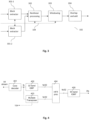
- Fig. 3 illustrates the operation of an example nonlinear subband block processing 102 with two subband inputs.
- the aim of the subband block processing is to implement the according transposition, time stretch, or a combination of transposition and time stretch of the combination of the two complex valued source subband signals in order to produce the target subband signal.
- the block extractor 301-1 samples a finite frame of samples from the first complex valued source subband and the block extractor 301-2 samples a finite frame of samples from the second complex valued source subband.
- one of the block extractors 301-1 and 301-2 may produce a single subband sample, i.e. one of the block extractors 301-1, 301-2 may apply a block length of one sample.
- the frames may be defined by a common input pointer position and the subband transposition factor.
- the two frames extracted in block extractors 301-1, 301-2, respectively, undergo nonlinear processing in unit 302.
- the nonlinear processing unit 302 typically generates a single output frame from the two input frames. Subsequently, the output frame is windowed by a finite length window in unit 203. The above process is repeated for a suite of frames which are generated from a suite of frames extracted from two subband signals using a block hop size.
- the suite of output frames is overlapped and added in an overlap and add unit 204.
- An iteration of this chain of operations will produce an output signal with duration being the subband stretch factor times the longest of the two input subband signals (up to the length of the synthesis window).
- the output signal will have complex frequencies transposed by the subband transposition factor.
- control data 104 may be used to modify the operation of the different blocks of the nonlinear processing 102, e.g. the operation of the block extractors 301-1, 301-2. Furthermore, it should be noted that the above operations are typically performed for all of the analysis subband signals provided by the analysis filterbank 101 and for all of the synthesis subband signals which are input into the synthesis filterbank 103.
- the two main configuration parameters of the overall harmonic transposer and/or time stretcher are the two main configuration parameters of the overall harmonic transposer and/or time stretcher.
- the filterbanks 101 and 103 can be of any complex exponential modulated type such as QMF or a windowed DFT or a wavelet transform.
- the analysis filterbank 101 and the synthesis filterbank 103 can be evenly or oddly stacked in the modulation and can be defined from a wide range of prototype filters and/or windows. Whereas all these second order choices affect the details in the subsequent design such as phase corrections and subband mapping management, the main system design parameters for the subband processing can typically be derived from the knowledge of the two quotients ⁇ t S / ⁇ t A and ⁇ f S / ⁇ f A of the following four filter bank parameters, all measured in physical units. In the above quotients,
- an input signal to the analysis filterbank 101 of physical duration D corresponds to a number D / ⁇ t A of analysis subband samples at the input to the subband processing unit 102. These D / ⁇ t A samples will be stretched to S ⁇ D / ⁇ t A samples by the subband processing unit 102 which applies the subband stretch factor S .
- n of the subband processing unit 102 for a given target or synthesis subband index m should obey n ⁇ ⁇ S ⁇ A ⁇ 1 Q ⁇ m .
- the subband index mapping may depend on the details of the filterbank parameters. In particular, if the fraction of the frequency spacing of the synthesis filterbank 103 and the analysis filterbank 101 is different from the physical transposition factor Q ⁇ , one or two source subbands may be assigned to a given target subband.
- the first and second source subbands are given by either ( n ( m ) ,n ( m ) + 1) or ( n ( m )+1, n ( m )).
- x ( k ) be the input signal to the block extractor 201
- p be the input block stride.
- I.e. x ( k ) is a complex valued analysis subband signal of an analysis subband with index n .
- the phase correction parameter ⁇ depends on the filterbank details and the source and target subband indices. In an embodiment, the phase correction parameter ⁇ may be determined experimentally by sweeping a set of input sinusoids. Furthermore, the phase correction parameter ⁇ may be derived by studying the phase difference of adjacent target subband complex sinusoids or by optimizing the performance for a Dirac pulse type of input signal.
- the phase modification factor T should be an integer such that the coefficients T - 1 and 1 are integers in the linear combination of phases in the first line of formula (5). With this assumption, i.e. with the assumption that the phase modification factor T is an integer, the result of the nonlinear modification is well defined even though phases are ambiguous by addition of arbitrary integer multiples of 2 ⁇ .
- formula (5) specifies that the phase of an output frame sample is determined by offsetting the phase of a corresponding input frame sample by a constant offset value.
- This constant offset value may depend on the modification factor T , which itself depends on the subband stretch factor and/or the subband transposition factor.
- the constant offset value may depend on the phase of a particular input frame sample from the input frame. This particular input frame sample is kept fixed for the determination of the phase of all the output frame samples of a given block. In the case of formula (5), the phase of the center sample of the input frame is used as the phase of the particular input frame sample.
- the constant offset value may depend on a phase correction parameter ⁇ which may e.g. be determined experimentally.
- the second line of formula (5) specifies that the magnitude of a sample of the output frame may depend on the magnitude of the corresponding sample of the input frame. Furthermore, the magnitude of a sample of the output frame may depend on the magnitude of a particular input frame sample. This particular input frame sample may be used for the determination of the magnitude of all the output frame samples. In the case of formula (5), the center sample of the input frame is used as the particular input frame sample. In an embodiment, the magnitude of a sample of the output frame may correspond to the geometrical mean of the magnitude of the corresponding sample of the input frame and the particular input frame sample.
- the overlap and add unit 204 applies a block stride of Sp, i.e. a time stride which is S times higher than the input block stride p . Due to this difference in time strides of formula (4) and (7) the duration of the output signal z ( k ) is S times the duration of the input signal x ( k ) , i.e. the synthesis subband signal has been stretched by the subband stretch factor S compared to the analysis subband signal. It should be noted that this observation typically applies if the length L of the window is negligible in comparison to the signal duration.
- the subband processing 102 may be further enhanced by applying control data 104.
- two configurations of the subband processing 102 sharing the same value of K in formula (11) and employing different block lengths may be used to implement a signal adaptive subband processing.
- the conceptual starting point in designing a signal adaptive configuration switching subband processing unit may be to imagine the two configurations running in parallel with a selector switch at their outputs, wherein the position of the selector switch depends on the control data 104.
- the sharing of K -value ensures that the switch is seamless in the case of a single complex sinusoid input.
- the hard switch on a subband signal level is automatically windowed by the surrounding filterbank framework 101, 103 so as to not introduce any switching artifacts on the final output signals. It can be shown that as a result of the overlap and add process in formula (7) an output identical to that of the conceptual switched system described above can be reproduced at the computational cost of the system of the configuration with the longest block, when the block sizes are sufficiently different, and the update rate of the control data is not too fast. Hence there is no penalty in computational complexity associated with a signal adaptive operation. According to the discussion above, the configuration with the shorter block length is more suitable for transient and low pitched periodical signals, whereas the configuration with longer block length is more suitable for stationary signals.
- a signal classifier may be used to classify excerpts of an audio signal into a transient class and a non-transient class, and to pass this classification information as control data 104 to the signal adaptive configuration switching subband processing unit 102.
- the subband processing unit 102 may use the control data 104 to set certain processing parameters, e.g. the block length of the block extractors.
- the first block extractor 301-1 uses a block length of L
- the second block extractor 301-2 uses a block length of 1.
- the rest of the processing in 203 and 204 is identical to the processing described in the context of the single input case. In other words, it is suggested to replace the particular frame sample of formula (5) by the single subband sample extracted from the respective other analysis subband signal.
- the ratio of the frequency spacing ⁇ f S of the synthesis filterbank 103 and the frequency spacing ⁇ f A of the analysis filterbank 101 is different from the desired physical transposition factor Q ⁇ , it may be beneficial to determine the samples of a synthesis subband with index m from two analysis subbands with index n , n +1, respectively.
- the corresponding index n may be given by the integer value obtained by truncating the analysis index value n given by formula (3).
- One of the analysis subband signals e.g. the analysis subband signal corresponding to index n , is fed into the first block extractor 301-1 and the other analysis subband signal, e.g.
- the one corresponding to index n +1 is fed into the second block extractor 301-2.
- a synthesis subband signal corresponding to index m is determined in accordance to the processing outlined above.
- the assignment of the adjacent analysis subband signals to the two block extractors 301-1 and 302-1 may by based on the remainder that is obtained when truncating the index value of formula (3), i.e. the difference of the exact index value given by formula (3) and the truncated integer value n obtained from formula (3). If the remainder is greater than 0.5, then the analysis subband signal corresponding to index n may be assigned to the second block extractor 301-2, otherwise this analysis subband signal may be assigned to the first block extractor 301-1.
- Fig. 4 illustrates an example scenario for the application of subband block based transposition using several orders of transposition in a HFR enhanced audio codec.
- a transmitted bit-stream is received at the core decoder 401, which provides a low bandwidth decoded core signal at a sampling frequency fs .
- This low bandwidth decoded core signal may also be referred to as the low frequency component of the audio signal.
- the signal at low sampling frequency fs may be re-sampled to the output sampling frequency 2 fs by means of a complex modulated 32 band QMF analysis bank 402 followed by a 64 band QMF synthesis bank (Inverse QMF) 405.
- Inverse QMF Inverse QMF
- the high frequency content of the output signal is obtained by feeding the higher subbands of the 64 band QMF synthesis bank 405 with the output bands from the multiple transposer unit 403, subject to spectral shaping and modification performed by the HFR processing unit 404.
- the multiple transposer 403 takes as input the decoded core signal and outputs a multitude of subband signals which represent the 64 QMF band analysis of a superposition or combination of several transposed signal components.
- the signal at the output of the multiple transposer 403 should correspond to the transposed synthesis subband signals which may be fed into a synthesis filterbank 103, which in the case of Fig. 4 is represented by the inverse QMF filterbank 405.
- a multiple transposer 403 Possible implementations of a multiple transposer 403 are outlined in the context of Figs. 5 and 6 .
- the HFR processing can sometimes compensate for poor transient response of the multiple transposer 403 but a consistently high quality can typically only be reached if the transient response of the multiple transposer itself is satisfactory.
- a transposer control signal 104 can affect the operation of the multiple transposer 403, and thereby ensure a satisfactory transient response of the multiple transposer 403.
- the above geometric weighting scheme may contribute to improving the transient response of the harmonic transposer 403.
- Fig. 5 illustrates an example scenario for the operation of a multiple order subband block based transposition unit 403 applying a separate analysis filter bank 502-2, 502-3, 502-4 per transposition order.
- the merging unit 504 selects and combines the relevant subbands from each transposition factor branch into a single multitude of QMF subbands to be fed into the HFR processing unit.
- the exemplary system includes a sampling rate converter 501-3 which converts the input sampling rate down by a factor 3/2 from fs to 2fs/3.
- the exemplary system includes a sampling rate converter 501-4 which converts the input sampling rate down by a factor two from fs to fs / 2 .
- the subband processing units 504-2 to 503-4 all perform pure subband signal stretches and employ the single input nonlinear subband block processing described in the context of Fig 2 .
- the control signal 104 may simultaneously affect the operation of all three subband processing units.
- the control signal 104 may be used to simultaneously switch between long block length processing and short block length processing depending on the type (transient or non-transient) of the excerpt of the input signal.
- Fig. 6 illustrates an example scenario for the efficient operation of a multiple order subband block based transposition applying a single 64 band QMF analysis filter bank.
- the use of three separate QMF analysis banks and two sampling rate converters in Fig. 5 results in a rather high computational complexity, as well as some implementation disadvantages for frame based processing due to the sampling rate conversion 501-3, i.e. a fractional sampling rate conversion. It is therefore suggested to replace the two transposition branches comprising units 501-3 ⁇ 502-3 ⁇ 503-3 and 501-4 ⁇ 502-4 ⁇ 503-4 by the subband processing units 603-3 and 603-4, respectively, whereas the branch 502-2 ⁇ 503-2 is kept unchanged compared to Fig 5 .
- formula (3) does not necessarily provide an integer valued index n for a target subband with index m .
- target subbands with index m for which formula (3) provides an integer value for index n , may be determined from the single source subband with index n (using formula (5)).
- a sufficiently high quality of harmonic transposition may be achieved by using subband processing units 603-3 and 603-4 which both make use of nonlinear subband block processing with two subband inputs as outlined in the context of Fig. 3 .
- the control signal 104 may simultaneously affect the operation of all three subband processing units.
- Fig. 7 illustrates an example transient response for a subband block based time stretch of a factor two.
- the top panel depicts the input signal, which is a castanet attack sampled at 16 kHz.
- a system based on the structure of Fig. 1 is designed with a 64 band QMF analysis filterbank 101 and a 64 band QMF synthesis filterbank 103.
- the window w is a raised cosine, e.g. a cosine raised to the power of 2.
- the transient response is significantly better in the latter case.
- harmonic transposition based HFR makes use of block based nonlinear subband processing.
- signal dependent control data is proposed to adapt the nonlinear subband processing to the type, e.g. transient or non-transient, of the signal.
- a geometrical weighting parameter is suggested in order to improve the transient response of harmonic transposition using block based nonlinear subband processing.
- a low complexity method and system for harmonic transposition based HFR is described which makes use of a single analysis / synthesis filterbank pair for harmonic transposition and HFR processing.
- the outlined methods and systems may be employed in various decoding devices, e.g. in multimedia receivers, video/audio settop boxes, mobile devices, audio players, video players, etc.
- the methods and systems for transposition and/or high frequency reconstruction and/or time stretching described in the present document may be implemented as software, firmware and/or hardware. Certain components may e.g. be implemented as software running on a digital signal processor or microprocessor. Other components may e.g. be implemented as hardware and or as application specific integrated circuits.
- the signals encountered in the described methods and systems may be stored on media such as random access memory or optical storage media. They may be transferred via networks, such as radio networks, satellite networks, wireless networks or wireline networks, e.g. the internet. Typical devices making use of the methods and systems described in the present document are portable electronic devices or other consumer equipment which are used to store and/or render audio signals.
- the methods and system may also be used on computer systems, e.g. internet web servers, which store and provide audio signals, e.g. music signals, for download.
- EEEs enumerated example embodiments
Landscapes
- Engineering & Computer Science (AREA)
- Physics & Mathematics (AREA)
- Acoustics & Sound (AREA)
- Multimedia (AREA)
- Health & Medical Sciences (AREA)
- Audiology, Speech & Language Pathology (AREA)
- Human Computer Interaction (AREA)
- Signal Processing (AREA)
- Computational Linguistics (AREA)
- Spectroscopy & Molecular Physics (AREA)
- Quality & Reliability (AREA)
- Compression, Expansion, Code Conversion, And Decoders (AREA)
- Vibration Dampers (AREA)
- Production Of Liquid Hydrocarbon Mixture For Refining Petroleum (AREA)
- Braking Arrangements (AREA)
- Superconductors And Manufacturing Methods Therefor (AREA)
- Superheterodyne Receivers (AREA)
Applications Claiming Priority (7)
| Application Number | Priority Date | Filing Date | Title |
|---|---|---|---|
| US29624110P | 2010-01-19 | 2010-01-19 | |
| US33154510P | 2010-05-05 | 2010-05-05 | |
| EP20206463.0A EP3806096B1 (en) | 2010-01-19 | 2011-01-05 | Improved subband block based harmonic transposition |
| EP22189432.2A EP4120263B1 (en) | 2010-01-19 | 2011-01-05 | Improved subband block based harmonic transposition |
| EP19175682.4A EP3564955B1 (en) | 2010-01-19 | 2011-01-05 | Improved subband block based harmonic transposition |
| EP11700033.1A EP2526550B1 (en) | 2010-01-19 | 2011-01-05 | Improved subband block based harmonic transposition |
| PCT/EP2011/050114 WO2011089029A1 (en) | 2010-01-19 | 2011-01-05 | Improved subband block based harmonic transposition |
Related Parent Applications (4)
| Application Number | Title | Priority Date | Filing Date |
|---|---|---|---|
| EP19175682.4A Division EP3564955B1 (en) | 2010-01-19 | 2011-01-05 | Improved subband block based harmonic transposition |
| EP22189432.2A Division EP4120263B1 (en) | 2010-01-19 | 2011-01-05 | Improved subband block based harmonic transposition |
| EP11700033.1A Division EP2526550B1 (en) | 2010-01-19 | 2011-01-05 | Improved subband block based harmonic transposition |
| EP20206463.0A Division EP3806096B1 (en) | 2010-01-19 | 2011-01-05 | Improved subband block based harmonic transposition |
Publications (1)
| Publication Number | Publication Date |
|---|---|
| EP4250290A1 true EP4250290A1 (en) | 2023-09-27 |
Family
ID=43531026
Family Applications (7)
| Application Number | Title | Priority Date | Filing Date |
|---|---|---|---|
| EP20206463.0A Active EP3806096B1 (en) | 2010-01-19 | 2011-01-05 | Improved subband block based harmonic transposition |
| EP19175681.6A Active EP3564954B1 (en) | 2010-01-19 | 2011-01-05 | Improved subband block based harmonic transposition |
| EP19175682.4A Active EP3564955B1 (en) | 2010-01-19 | 2011-01-05 | Improved subband block based harmonic transposition |
| EP22189432.2A Active EP4120263B1 (en) | 2010-01-19 | 2011-01-05 | Improved subband block based harmonic transposition |
| EP11700033.1A Active EP2526550B1 (en) | 2010-01-19 | 2011-01-05 | Improved subband block based harmonic transposition |
| EP23190357.6A Pending EP4250290A1 (en) | 2010-01-19 | 2011-01-05 | Improved subband block based harmonic transposition |
| EP22189443.9A Active EP4120264B1 (en) | 2010-01-19 | 2011-01-05 | Improved subband block based harmonic transposition |
Family Applications Before (5)
| Application Number | Title | Priority Date | Filing Date |
|---|---|---|---|
| EP20206463.0A Active EP3806096B1 (en) | 2010-01-19 | 2011-01-05 | Improved subband block based harmonic transposition |
| EP19175681.6A Active EP3564954B1 (en) | 2010-01-19 | 2011-01-05 | Improved subband block based harmonic transposition |
| EP19175682.4A Active EP3564955B1 (en) | 2010-01-19 | 2011-01-05 | Improved subband block based harmonic transposition |
| EP22189432.2A Active EP4120263B1 (en) | 2010-01-19 | 2011-01-05 | Improved subband block based harmonic transposition |
| EP11700033.1A Active EP2526550B1 (en) | 2010-01-19 | 2011-01-05 | Improved subband block based harmonic transposition |
Family Applications After (1)
| Application Number | Title | Priority Date | Filing Date |
|---|---|---|---|
| EP22189443.9A Active EP4120264B1 (en) | 2010-01-19 | 2011-01-05 | Improved subband block based harmonic transposition |
Country Status (17)
| Country | Link |
|---|---|
| US (10) | US8898067B2 (ko) |
| EP (7) | EP3806096B1 (ko) |
| JP (8) | JP5329717B2 (ko) |
| KR (13) | KR101783818B1 (ko) |
| CN (4) | CN104318929B (ko) |
| AU (1) | AU2011208899B2 (ko) |
| BR (6) | BR122019025143B1 (ko) |
| CA (9) | CA3038582C (ko) |
| CL (1) | CL2012001990A1 (ko) |
| ES (6) | ES2836756T3 (ko) |
| MX (1) | MX2012007942A (ko) |
| MY (2) | MY164396A (ko) |
| PL (6) | PL3806096T3 (ko) |
| RU (3) | RU2518682C2 (ko) |
| SG (3) | SG182269A1 (ko) |
| UA (1) | UA102347C2 (ko) |
| WO (1) | WO2011089029A1 (ko) |
Families Citing this family (16)
| Publication number | Priority date | Publication date | Assignee | Title |
|---|---|---|---|---|
| MY164396A (en) | 2010-01-19 | 2017-12-15 | Dolby Int Ab | Subband block based harmonic transposition |
| US8958510B1 (en) * | 2010-06-10 | 2015-02-17 | Fredric J. Harris | Selectable bandwidth filter |
| SG10201506914PA (en) | 2010-09-16 | 2015-10-29 | Dolby Int Ab | Cross product enhanced subband block based harmonic transposition |
| EP2682941A1 (de) * | 2012-07-02 | 2014-01-08 | Technische Universität Ilmenau | Vorrichtung, Verfahren und Computerprogramm für frei wählbare Frequenzverschiebungen in der Subband-Domäne |
| JP2014041240A (ja) * | 2012-08-22 | 2014-03-06 | Pioneer Electronic Corp | タイムスケーリング方法、ピッチシフト方法、オーディオデータ処理装置およびプログラム |
| CN106847297B (zh) * | 2013-01-29 | 2020-07-07 | 华为技术有限公司 | 高频带信号的预测方法、编/解码设备 |
| WO2015036348A1 (en) * | 2013-09-12 | 2015-03-19 | Dolby International Ab | Time- alignment of qmf based processing data |
| US9306606B2 (en) * | 2014-06-10 | 2016-04-05 | The Boeing Company | Nonlinear filtering using polyphase filter banks |
| EP2963648A1 (en) * | 2014-07-01 | 2016-01-06 | Fraunhofer-Gesellschaft zur Förderung der angewandten Forschung e.V. | Audio processor and method for processing an audio signal using vertical phase correction |
| US10129659B2 (en) | 2015-05-08 | 2018-11-13 | Doly International AB | Dialog enhancement complemented with frequency transposition |
| BR112018005391B1 (pt) * | 2015-09-22 | 2023-11-21 | Koninklijke Philips N.V | Aparelho para processamento de sinais de áudio, método de processamento de sinais de áudio, e dispositivo |
| TW202341126A (zh) * | 2017-03-23 | 2023-10-16 | 瑞典商都比國際公司 | 用於音訊信號之高頻重建的諧波轉置器的回溯相容整合 |
| EP3616196A4 (en) * | 2017-04-28 | 2021-01-20 | DTS, Inc. | AUDIO ENCODER WINDOW AND TRANSFORMATION IMPLEMENTATIONS |
| WO2019199701A1 (en) | 2018-04-09 | 2019-10-17 | Dolby Laboratories Licensing Corporation | Hdr image representations using neural network mappings |
| CN114242088A (zh) * | 2018-04-25 | 2022-03-25 | 杜比国际公司 | 具有减少后处理延迟的高频重建技术的集成 |
| MX2020011206A (es) * | 2018-04-25 | 2020-11-13 | Dolby Int Ab | Integracion de tecnicas de reconstruccion de alta frecuencia con retraso post-procesamiento reducido. |
Citations (2)
| Publication number | Priority date | Publication date | Assignee | Title |
|---|---|---|---|---|
| WO1998057436A2 (en) | 1997-06-10 | 1998-12-17 | Lars Gustaf Liljeryd | Source coding enhancement using spectral-band replication |
| WO2002052545A1 (en) | 2000-12-22 | 2002-07-04 | Coding Technologies Sweden Ab | Enhancing source coding systems by adaptive transposition |
Family Cites Families (41)
| Publication number | Priority date | Publication date | Assignee | Title |
|---|---|---|---|---|
| KR100261253B1 (ko) | 1997-04-02 | 2000-07-01 | 윤종용 | 비트율 조절이 가능한 오디오 부호화/복호화 방법및 장치 |
| RU2256293C2 (ru) | 1997-06-10 | 2005-07-10 | Коудинг Технолоджиз Аб | Усовершенствование исходного кодирования с использованием дублирования спектральной полосы |
| JP3442974B2 (ja) | 1997-07-30 | 2003-09-02 | 本田技研工業株式会社 | 吸収式冷凍機の精留装置 |
| US6266003B1 (en) * | 1998-08-28 | 2001-07-24 | Sigma Audio Research Limited | Method and apparatus for signal processing for time-scale and/or pitch modification of audio signals |
| AUPP829899A0 (en) * | 1999-01-27 | 1999-02-18 | Motorola Australia Pty Ltd | Method and apparatus for time-warping a digitised waveform to have an approximately fixed period |
| JP3848181B2 (ja) * | 2002-03-07 | 2006-11-22 | キヤノン株式会社 | 音声合成装置及びその方法、プログラム |
| US20030187663A1 (en) * | 2002-03-28 | 2003-10-02 | Truman Michael Mead | Broadband frequency translation for high frequency regeneration |
| US7447631B2 (en) * | 2002-06-17 | 2008-11-04 | Dolby Laboratories Licensing Corporation | Audio coding system using spectral hole filling |
| TWI288915B (en) * | 2002-06-17 | 2007-10-21 | Dolby Lab Licensing Corp | Improved audio coding system using characteristics of a decoded signal to adapt synthesized spectral components |
| JP4227772B2 (ja) * | 2002-07-19 | 2009-02-18 | 日本電気株式会社 | オーディオ復号装置と復号方法およびプログラム |
| CA2399159A1 (en) * | 2002-08-16 | 2004-02-16 | Dspfactory Ltd. | Convergence improvement for oversampled subband adaptive filters |
| ATE318405T1 (de) | 2002-09-19 | 2006-03-15 | Matsushita Electric Ind Co Ltd | Audiodecodierungsvorrichtung und -verfahren |
| RU2271578C2 (ru) * | 2003-01-31 | 2006-03-10 | Ооо "Центр Речевых Технологий" | Способ распознавания речевых команд управления |
| US7318035B2 (en) | 2003-05-08 | 2008-01-08 | Dolby Laboratories Licensing Corporation | Audio coding systems and methods using spectral component coupling and spectral component regeneration |
| PL1683133T3 (pl) * | 2003-10-30 | 2007-07-31 | Koninl Philips Electronics Nv | Kodowanie lub dekodowanie sygnału audio |
| CA2454296A1 (en) * | 2003-12-29 | 2005-06-29 | Nokia Corporation | Method and device for speech enhancement in the presence of background noise |
| US7272567B2 (en) * | 2004-03-25 | 2007-09-18 | Zoran Fejzo | Scalable lossless audio codec and authoring tool |
| JP2006070768A (ja) | 2004-09-01 | 2006-03-16 | Honda Motor Co Ltd | 蒸発燃料処理装置 |
| RU2500043C2 (ru) | 2004-11-05 | 2013-11-27 | Панасоник Корпорэйшн | Кодер, декодер, способ кодирования и способ декодирования |
| US7472041B2 (en) | 2005-08-26 | 2008-12-30 | Step Communications Corporation | Method and apparatus for accommodating device and/or signal mismatch in a sensor array |
| US7917561B2 (en) | 2005-09-16 | 2011-03-29 | Coding Technologies Ab | Partially complex modulated filter bank |
| JP4760278B2 (ja) | 2005-10-04 | 2011-08-31 | 株式会社ケンウッド | 補間装置、オーディオ再生装置、補間方法および補間プログラム |
| US20070083365A1 (en) * | 2005-10-06 | 2007-04-12 | Dts, Inc. | Neural network classifier for separating audio sources from a monophonic audio signal |
| JP4693584B2 (ja) * | 2005-10-18 | 2011-06-01 | 三洋電機株式会社 | アクセス制御装置 |
| TWI311856B (en) | 2006-01-04 | 2009-07-01 | Quanta Comp Inc | Synthesis subband filtering method and apparatus |
| KR100754220B1 (ko) | 2006-03-07 | 2007-09-03 | 삼성전자주식회사 | Mpeg 서라운드를 위한 바이노럴 디코더 및 그 디코딩방법 |
| US8150065B2 (en) | 2006-05-25 | 2012-04-03 | Audience, Inc. | System and method for processing an audio signal |
| CN101617360B (zh) * | 2006-09-29 | 2012-08-22 | 韩国电子通信研究院 | 用于编码和解码具有各种声道的多对象音频信号的设备和方法 |
| ES2834024T3 (es) | 2006-10-25 | 2021-06-16 | Fraunhofer Ges Forschung | Aparato y procedimiento para la generación de muestras de audio en el dominio temporal |
| JP5141180B2 (ja) * | 2006-11-09 | 2013-02-13 | ソニー株式会社 | 周波数帯域拡大装置及び周波数帯域拡大方法、再生装置及び再生方法、並びに、プログラム及び記録媒体 |
| JP5103880B2 (ja) * | 2006-11-24 | 2012-12-19 | 富士通株式会社 | 復号化装置および復号化方法 |
| JP2009116245A (ja) * | 2007-11-09 | 2009-05-28 | Yamaha Corp | 音声強調装置 |
| DE102008015702B4 (de) * | 2008-01-31 | 2010-03-11 | Fraunhofer-Gesellschaft zur Förderung der angewandten Forschung e.V. | Vorrichtung und Verfahren zur Bandbreitenerweiterung eines Audiosignals |
| AU2009267529B2 (en) * | 2008-07-11 | 2011-03-03 | Fraunhofer-Gesellschaft Zur Foerderung Der Angewandten Forschung E.V. | Apparatus and method for calculating bandwidth extension data using a spectral tilt controlling framing |
| JP5255699B2 (ja) * | 2008-07-11 | 2013-08-07 | フラウンホーファー−ゲゼルシャフト・ツール・フェルデルング・デル・アンゲヴァンテン・フォルシュング・アインゲトラーゲネル・フェライン | 帯域幅拡張信号の生成装置及び生成方法 |
| BR122019023684B1 (pt) | 2009-01-16 | 2020-05-05 | Dolby Int Ab | sistema para gerar um componente de frequência alta de um sinal de áudio e método para realizar reconstrução de frequência alta de um componente de frequência alta |
| EP2239732A1 (en) * | 2009-04-09 | 2010-10-13 | Fraunhofer-Gesellschaft zur Förderung der Angewandten Forschung e.V. | Apparatus and method for generating a synthesis audio signal and for encoding an audio signal |
| TWI643187B (zh) * | 2009-05-27 | 2018-12-01 | 瑞典商杜比國際公司 | 從訊號的低頻成份產生該訊號之高頻成份的系統與方法,及其機上盒、電腦程式產品、軟體程式及儲存媒體 |
| MY164396A (en) | 2010-01-19 | 2017-12-15 | Dolby Int Ab | Subband block based harmonic transposition |
| JP2013153596A (ja) * | 2012-01-25 | 2013-08-08 | Hitachi Ulsi Systems Co Ltd | 充放電監視装置およびバッテリパック |
| CN105700923A (zh) | 2016-01-08 | 2016-06-22 | 深圳市创想天空科技股份有限公司 | 安装应用程序的方法及系统 |
-
2011
- 2011-01-05 MY MYPI2012002842A patent/MY164396A/en unknown
- 2011-01-05 KR KR1020177013777A patent/KR101783818B1/ko active IP Right Grant
- 2011-01-05 KR KR1020207037531A patent/KR102343135B1/ko active IP Right Grant
- 2011-01-05 SG SG2012045795A patent/SG182269A1/en unknown
- 2011-01-05 MX MX2012007942A patent/MX2012007942A/es active IP Right Grant
- 2011-01-05 AU AU2011208899A patent/AU2011208899B2/en active Active
- 2011-01-05 KR KR1020177027021A patent/KR101858948B1/ko active IP Right Grant
- 2011-01-05 CN CN201410461154.0A patent/CN104318929B/zh active Active
- 2011-01-05 KR KR1020137023416A patent/KR101663578B1/ko active IP Right Grant
- 2011-01-05 KR KR1020197025724A patent/KR102091677B1/ko active IP Right Grant
- 2011-01-05 CA CA3038582A patent/CA3038582C/en active Active
- 2011-01-05 CA CA2945730A patent/CA2945730C/en active Active
- 2011-01-05 UA UAA201208556A patent/UA102347C2/ru unknown
- 2011-01-05 BR BR122019025143-6A patent/BR122019025143B1/pt active IP Right Grant
- 2011-01-05 EP EP20206463.0A patent/EP3806096B1/en active Active
- 2011-01-05 BR BR112012017651-0A patent/BR112012017651B1/pt active IP Right Grant
- 2011-01-05 KR KR1020227043442A patent/KR20230003596A/ko active IP Right Grant
- 2011-01-05 CA CA3107943A patent/CA3107943C/en active Active
- 2011-01-05 ES ES19175681T patent/ES2836756T3/es active Active
- 2011-01-05 CA CA2784564A patent/CA2784564C/en active Active
- 2011-01-05 ES ES22189443T patent/ES2955433T3/es active Active
- 2011-01-05 PL PL20206463.0T patent/PL3806096T3/pl unknown
- 2011-01-05 EP EP19175681.6A patent/EP3564954B1/en active Active
- 2011-01-05 EP EP19175682.4A patent/EP3564955B1/en active Active
- 2011-01-05 PL PL22189443.9T patent/PL4120264T3/pl unknown
- 2011-01-05 CN CN201410461177.1A patent/CN104318930B/zh active Active
- 2011-01-05 ES ES20206463T patent/ES2930203T3/es active Active
- 2011-01-05 JP JP2012547509A patent/JP5329717B2/ja active Active
- 2011-01-05 EP EP22189432.2A patent/EP4120263B1/en active Active
- 2011-01-05 CN CN201180006569.3A patent/CN102741921B/zh active Active
- 2011-01-05 CA CA3008914A patent/CA3008914C/en active Active
- 2011-01-05 BR BR122019025134-7A patent/BR122019025134B1/pt active IP Right Grant
- 2011-01-05 PL PL19175682T patent/PL3564955T3/pl unknown
- 2011-01-05 CA CA3200142A patent/CA3200142C/en active Active
- 2011-01-05 ES ES22189432T patent/ES2955432T3/es active Active
- 2011-01-05 CA CA3225485A patent/CA3225485A1/en active Pending
- 2011-01-05 RU RU2012128847/08A patent/RU2518682C2/ru active
- 2011-01-05 PL PL11700033T patent/PL2526550T3/pl unknown
- 2011-01-05 CN CN201410460670.1A patent/CN104318928B/zh active Active
- 2011-01-05 EP EP11700033.1A patent/EP2526550B1/en active Active
- 2011-01-05 KR KR1020207007483A patent/KR102198688B1/ko active IP Right Grant
- 2011-01-05 CA CA3074099A patent/CA3074099C/en active Active
- 2011-01-05 KR KR1020167027183A patent/KR101740912B1/ko active IP Right Grant
- 2011-01-05 KR KR1020217041623A patent/KR102478321B1/ko active IP Right Grant
- 2011-01-05 SG SG10201408425QA patent/SG10201408425QA/en unknown
- 2011-01-05 BR BR122020020536-9A patent/BR122020020536B1/pt active IP Right Grant
- 2011-01-05 CA CA3166284A patent/CA3166284C/en active Active
- 2011-01-05 EP EP23190357.6A patent/EP4250290A1/en active Pending
- 2011-01-05 ES ES11700033T patent/ES2734179T3/es active Active
- 2011-01-05 SG SG10202101744YA patent/SG10202101744YA/en unknown
- 2011-01-05 BR BR122019025154-1A patent/BR122019025154B1/pt active IP Right Grant
- 2011-01-05 ES ES19175682T patent/ES2841924T3/es active Active
- 2011-01-05 KR KR1020127018729A patent/KR101343795B1/ko active IP Right Grant
- 2011-01-05 WO PCT/EP2011/050114 patent/WO2011089029A1/en active Application Filing
- 2011-01-05 KR KR1020187013166A patent/KR101902863B1/ko active IP Right Grant
- 2011-01-05 BR BR122019025131-2A patent/BR122019025131B1/pt active IP Right Grant
- 2011-01-05 KR KR1020197008506A patent/KR102020334B1/ko active IP Right Grant
- 2011-01-05 US US13/514,896 patent/US8898067B2/en active Active
- 2011-01-05 KR KR1020187027030A patent/KR101964179B1/ko active IP Right Grant
- 2011-01-05 EP EP22189443.9A patent/EP4120264B1/en active Active
- 2011-01-05 PL PL22189432.2T patent/PL4120263T3/pl unknown
- 2011-01-05 PL PL19175681T patent/PL3564954T3/pl unknown
-
2012
- 2012-07-18 CL CL2012001990A patent/CL2012001990A1/es unknown
-
2013
- 2013-07-24 JP JP2013153596A patent/JP5792234B2/ja active Active
-
2014
- 2014-01-13 RU RU2014100648A patent/RU2644527C2/ru active
- 2014-10-13 US US14/512,833 patent/US9431025B2/en active Active
-
2015
- 2015-08-05 JP JP2015154976A patent/JP6189376B2/ja active Active
-
2016
- 2016-08-02 US US15/226,272 patent/US9741362B2/en active Active
-
2017
- 2017-07-10 US US15/644,983 patent/US9858945B2/en active Active
- 2017-08-02 JP JP2017149826A patent/JP6426244B2/ja active Active
- 2017-11-27 US US15/822,305 patent/US10109296B2/en active Active
-
2018
- 2018-01-12 RU RU2018101155A patent/RU2665298C1/ru active
- 2018-09-19 US US16/135,284 patent/US10699728B2/en active Active
- 2018-10-24 JP JP2018200065A patent/JP6644856B2/ja active Active
-
2020
- 2020-01-08 JP JP2020001199A patent/JP6834034B2/ja active Active
- 2020-06-23 US US16/908,745 patent/US11341984B2/en active Active
- 2020-08-24 MY MYPI2020004336A patent/MY197452A/en unknown
-
2021
- 2021-02-03 JP JP2021015546A patent/JP7160968B2/ja active Active
-
2022
- 2022-05-23 US US17/751,214 patent/US11646047B2/en active Active
- 2022-10-13 JP JP2022164642A patent/JP7475410B2/ja active Active
-
2023
- 2023-03-30 US US18/192,982 patent/US11935555B2/en active Active
- 2023-12-20 US US18/390,953 patent/US20240127845A1/en active Pending
Patent Citations (2)
| Publication number | Priority date | Publication date | Assignee | Title |
|---|---|---|---|---|
| WO1998057436A2 (en) | 1997-06-10 | 1998-12-17 | Lars Gustaf Liljeryd | Source coding enhancement using spectral-band replication |
| WO2002052545A1 (en) | 2000-12-22 | 2002-07-04 | Coding Technologies Sweden Ab | Enhancing source coding systems by adaptive transposition |
Non-Patent Citations (3)
| Title |
|---|
| FREDERIK NAGEL ET AL: "A HARMONIC BANDWIDTH EXTENSION METHOD FOR AUDIO CODECS", INTERNATIONAL CONFERENCE ON ACOUSTICS, SPEECH AND SIGNAL PROCESSING 2009, TAIPEI, 19 April 2009 (2009-04-19), pages 145 - 148, XP002527507 * |
| PER EKSTRAND ET AL: "WD text for USAC CE on Harmonic Transposer", 91. MPEG MEETING; 18-1-2010 - 22-1-2010; KYOTO; (MOTION PICTURE EXPERT GROUP OR ISO/IEC JTC1/SC29/WG11),, 16 January 2010 (2010-01-16), XP030045756 * |
| ZHOU HUAN ET AL: "Core Experiment on the eSBR module of USAC", 90. MPEG MEETING; 26-10-2009 - 30-10-2009; XIAN; (MOTION PICTURE EXPERT GROUP OR ISO/IEC JTC1/SC29/WG11),, no. M16933, 23 October 2009 (2009-10-23), XP030045523 * |
Also Published As
Similar Documents
| Publication | Publication Date | Title |
|---|---|---|
| US11935555B2 (en) | Subband block based harmonic transposition | |
| AU2022231727B2 (en) | Improved Subband Block Based Harmonic Transposition | |
| AU2019240701B2 (en) | Improved Subband Block Based Harmonic Transposition |
Legal Events
| Date | Code | Title | Description |
|---|---|---|---|
| PUAI | Public reference made under article 153(3) epc to a published international application that has entered the european phase |
Free format text: ORIGINAL CODE: 0009012 |
|
| STAA | Information on the status of an ep patent application or granted ep patent |
Free format text: STATUS: THE APPLICATION HAS BEEN PUBLISHED |
|
| AC | Divisional application: reference to earlier application |
Ref document number: 2526550 Country of ref document: EP Kind code of ref document: P Ref document number: 3564955 Country of ref document: EP Kind code of ref document: P Ref document number: 3806096 Country of ref document: EP Kind code of ref document: P Ref document number: 4120263 Country of ref document: EP Kind code of ref document: P |
|
| AK | Designated contracting states |
Kind code of ref document: A1 Designated state(s): AL AT BE BG CH CY CZ DE DK EE ES FI FR GB GR HR HU IE IS IT LI LT LU LV MC MK MT NL NO PL PT RO RS SE SI SK SM TR |
|
| P01 | Opt-out of the competence of the unified patent court (upc) registered |
Effective date: 20231113 |
|
| REG | Reference to a national code |
Ref country code: HK Ref legal event code: DE Ref document number: 40094424 Country of ref document: HK |
|
| STAA | Information on the status of an ep patent application or granted ep patent |
Free format text: STATUS: REQUEST FOR EXAMINATION WAS MADE |
|
| GRAP | Despatch of communication of intention to grant a patent |
Free format text: ORIGINAL CODE: EPIDOSNIGR1 |
|
| STAA | Information on the status of an ep patent application or granted ep patent |
Free format text: STATUS: GRANT OF PATENT IS INTENDED |
|
| 17P | Request for examination filed |
Effective date: 20240319 |
|
| RBV | Designated contracting states (corrected) |
Designated state(s): AL AT BE BG CH CY CZ DE DK EE ES FI FR GB GR HR HU IE IS IT LI LT LU LV MC MK MT NL NO PL PT RO RS SE SI SK SM TR |
|
| INTG | Intention to grant announced |
Effective date: 20240418 |