EP4250175A1 - Printing apparatus and method of printing - Google Patents
Printing apparatus and method of printing Download PDFInfo
- Publication number
- EP4250175A1 EP4250175A1 EP23163802.4A EP23163802A EP4250175A1 EP 4250175 A1 EP4250175 A1 EP 4250175A1 EP 23163802 A EP23163802 A EP 23163802A EP 4250175 A1 EP4250175 A1 EP 4250175A1
- Authority
- EP
- European Patent Office
- Prior art keywords
- medium
- carriage
- printing
- transport
- head
- Prior art date
- Legal status (The legal status is an assumption and is not a legal conclusion. Google has not performed a legal analysis and makes no representation as to the accuracy of the status listed.)
- Granted
Links
Images





Classifications
-
- B—PERFORMING OPERATIONS; TRANSPORTING
- B41—PRINTING; LINING MACHINES; TYPEWRITERS; STAMPS
- B41J—TYPEWRITERS; SELECTIVE PRINTING MECHANISMS, i.e. MECHANISMS PRINTING OTHERWISE THAN FROM A FORME; CORRECTION OF TYPOGRAPHICAL ERRORS
- B41J11/00—Devices or arrangements of selective printing mechanisms, e.g. ink-jet printers or thermal printers, for supporting or handling copy material in sheet or web form
-
- B—PERFORMING OPERATIONS; TRANSPORTING
- B41—PRINTING; LINING MACHINES; TYPEWRITERS; STAMPS
- B41J—TYPEWRITERS; SELECTIVE PRINTING MECHANISMS, i.e. MECHANISMS PRINTING OTHERWISE THAN FROM A FORME; CORRECTION OF TYPOGRAPHICAL ERRORS
- B41J25/00—Actions or mechanisms not otherwise provided for
- B41J25/001—Mechanisms for bodily moving print heads or carriages parallel to the paper surface
- B41J25/006—Mechanisms for bodily moving print heads or carriages parallel to the paper surface for oscillating, e.g. page-width print heads provided with counter-balancing means or shock absorbers
-
- G—PHYSICS
- G06—COMPUTING OR CALCULATING; COUNTING
- G06K—GRAPHICAL DATA READING; PRESENTATION OF DATA; RECORD CARRIERS; HANDLING RECORD CARRIERS
- G06K15/00—Arrangements for producing a permanent visual presentation of the output data, e.g. computer output printers
- G06K15/02—Arrangements for producing a permanent visual presentation of the output data, e.g. computer output printers using printers
- G06K15/16—Means for paper feeding or form feeding
-
- B—PERFORMING OPERATIONS; TRANSPORTING
- B41—PRINTING; LINING MACHINES; TYPEWRITERS; STAMPS
- B41J—TYPEWRITERS; SELECTIVE PRINTING MECHANISMS, i.e. MECHANISMS PRINTING OTHERWISE THAN FROM A FORME; CORRECTION OF TYPOGRAPHICAL ERRORS
- B41J11/00—Devices or arrangements of selective printing mechanisms, e.g. ink-jet printers or thermal printers, for supporting or handling copy material in sheet or web form
- B41J11/008—Controlling printhead for accurately positioning print image on printing material, e.g. with the intention to control the width of margins
-
- B—PERFORMING OPERATIONS; TRANSPORTING
- B41—PRINTING; LINING MACHINES; TYPEWRITERS; STAMPS
- B41J—TYPEWRITERS; SELECTIVE PRINTING MECHANISMS, i.e. MECHANISMS PRINTING OTHERWISE THAN FROM A FORME; CORRECTION OF TYPOGRAPHICAL ERRORS
- B41J11/00—Devices or arrangements of selective printing mechanisms, e.g. ink-jet printers or thermal printers, for supporting or handling copy material in sheet or web form
- B41J11/36—Blanking or long feeds; Feeding to a particular line, e.g. by rotation of platen or feed roller
- B41J11/42—Controlling printing material conveyance for accurate alignment of the printing material with the printhead; Print registering
-
- B—PERFORMING OPERATIONS; TRANSPORTING
- B41—PRINTING; LINING MACHINES; TYPEWRITERS; STAMPS
- B41J—TYPEWRITERS; SELECTIVE PRINTING MECHANISMS, i.e. MECHANISMS PRINTING OTHERWISE THAN FROM A FORME; CORRECTION OF TYPOGRAPHICAL ERRORS
- B41J25/00—Actions or mechanisms not otherwise provided for
- B41J25/001—Mechanisms for bodily moving print heads or carriages parallel to the paper surface
-
- B—PERFORMING OPERATIONS; TRANSPORTING
- B41—PRINTING; LINING MACHINES; TYPEWRITERS; STAMPS
- B41J—TYPEWRITERS; SELECTIVE PRINTING MECHANISMS, i.e. MECHANISMS PRINTING OTHERWISE THAN FROM A FORME; CORRECTION OF TYPOGRAPHICAL ERRORS
- B41J15/00—Devices or arrangements of selective printing mechanisms, e.g. ink-jet printers or thermal printers, specially adapted for supporting or handling copy material in continuous form, e.g. webs
- B41J15/04—Supporting, feeding, or guiding devices; Mountings for web rolls or spindles
-
- B—PERFORMING OPERATIONS; TRANSPORTING
- B41—PRINTING; LINING MACHINES; TYPEWRITERS; STAMPS
- B41J—TYPEWRITERS; SELECTIVE PRINTING MECHANISMS, i.e. MECHANISMS PRINTING OTHERWISE THAN FROM A FORME; CORRECTION OF TYPOGRAPHICAL ERRORS
- B41J2/00—Typewriters or selective printing mechanisms characterised by the printing or marking process for which they are designed
- B41J2/005—Typewriters or selective printing mechanisms characterised by the printing or marking process for which they are designed characterised by bringing liquid or particles selectively into contact with a printing material
- B41J2/01—Ink jet
- B41J2/21—Ink jet for multi-colour printing
- B41J2/2132—Print quality control characterised by dot disposition, e.g. for reducing white stripes or banding
Definitions
- the present disclosure relates to a printing apparatus and a method of printing.
- a printing apparatus in JP-A-2012-152957 , includes a head for discharging a liquid onto a medium, a carriage on which the head is mounted, and a transport unit that transports the medium. During a period in which the transport of the medium by the transport unit is stopped, the head discharges the liquid onto the medium while moving together with the carriage. During a period in which the carriage stops, the transport unit transports the medium.
- a printing apparatus that solves the problem described above includes a transport unit configured to intermittently transport a medium, a support portion configured to support the medium, a head configured to perform printing by discharging a liquid onto the medium supported by the support portion, during a period in which the transport of the medium by the transport unit is stopped, a carriage at which the head is mounted and that is configured to move relative to the medium, and a control unit, wherein the control unit causes the head to discharge the liquid onto a printing region while moving the carriage, the printing region being a region, of the medium, supported by the support portion, and starts the transport of the medium by the transport unit after the discharge of the liquid by the head is completed and before the carriage stops.
- a method of printing that solves the problem described above includes causing a head to discharge a liquid onto a printing region while moving a carriage, the printing region being a region, of a medium, supported by a support portion, and starting transport of the medium by a transport unit after the discharge of the liquid by the head is completed and before the carriage stops.
- the printing apparatus is, for example, an ink jet-type printer that prints an image of characters, photographs, and the like on a medium such as a sheet and fabric by discharging ink, which is an example of a liquid.
- the printing apparatus is, for example, a label printer.
- a printing apparatus 11 includes a housing 12.
- the printing apparatus 11 includes a feeding unit 13 that feeds a medium 99.
- the feeding unit 13 is configured to feed the medium 99.
- the feeding unit 13 is accommodated in the housing 12, for example.
- the feeding unit 13 includes a feeding shaft 14.
- the feeding shaft 14 rotatably holds a roll body 100 around which the medium 99 is wound.
- the feeding shaft 14 holds the medium 99 before printing.
- the feeding shaft 14 may be driven to rotate by a motor, or may be driven to rotate as a result of the medium 99 being pulled.
- the printing apparatus 11 includes a winding unit 15.
- the winding unit 15 is configured to take up the medium 99.
- the winding unit 15 is accommodated in the housing 22, for example.
- the winding unit 15 includes a winding shaft 16.
- the winding shaft 16 rotatably holds the roll body 100.
- the winding shaft 16 holds the medium 99 after the printing.
- the winding shaft 16 rotates, the winding unit 15 takes up the medium 99.
- the winding shaft 16 is driven to rotate by a motor, for example.
- the printing apparatus 11 includes a support portion 17.
- the support portion 17 supports the medium 99.
- the support portion 17 is accommodated in the housing 12, for example.
- the support portion 17 support the medium 99 from below, for example.
- the support portion 17 supports the medium 99 in a process from when the medium 99 is fed from the feeding unit 13 until when the medium 99 is taken up by the winding unit 15.
- the support portion 17 includes a support face 18.
- the support face 18 is a surface that comes into contact with the medium 99 at the support portion 17.
- the support face 18 faces upward at the support portion 17, for example.
- a region supported by the support portion 17 is a printing region PA.
- the printing is performed on the printing region PA of the medium 99.
- the printing region PA is a region, of the medium 99, that overlaps with the support portion 17 when the support portion 17 is viewed from a position facing the support face 18. In other words, when the support portion 17 is viewed in plan view, the printing region PA overlaps with the support face 18.
- the printing region PA is, for example, the entire region of the medium 99 supported by the support portion 17.
- the printing region PA is not limited to the entire region of the medium 99 supported by the support portion 17, but may be a portion of the region supported by the support portion 17.
- the printing region PA refers to the maximum region on which the printing apparatus 11 can perform the printing, of the region supported by the support portion 17.
- the support portion 17 includes one or a plurality of through-holes 19.
- the through-hole 19 opens to the support face 18.
- the through-hole 19 is covered by the medium 99 positioned on the support face 18, for example.
- the printing apparatus 11 includes a sucking unit 21.
- the sucking unit 21 is configured to cause the medium 99 to be sucked to the support portion 17.
- the sucking unit 21 sucks the medium 99 against the support portion 17, for example, by suctioning the medium 99 through the support portion 17.
- the sucking unit 21 includes a suction pump, for example.
- the sucking unit 21 suctions the medium 99 through the through-hole 19. As a result, the medium 99 is sucked to the support face 18.
- the sucking unit 21 may cause the medium 99 to be sucked to the support portion 17 by generating static electricity, for example.
- the sucking unit 21 can change the sucking force thereof, for example, by controlling the suction force.
- the sucking unit 21 changes the sucking force, for example, in accordance with the transport of the medium 99. For example, when the medium 99 is being transported, the sucking force of the sucking unit 21 is reduced compared to when the transport of the medium 99 is stopped.
- the sucking unit 21 causes the sucking force thereof to be relatively small. By causing the sucking force of the sucking unit 21 to be relatively small when the medium 99 is being transported, the medium 99 can easily move on the support portion 17.
- the sucking unit 21 causes the sucking force thereof to be relatively large. By causing the sucking force of the sucking unit 21 to be relatively large when the transport of the medium 99 is stopped, the position of the medium 99 is less likely to be displaced on the support portion 17.
- the printing apparatus 12 includes a transport unit 22.
- the transport unit 22 is configured to transport the medium 99.
- the transport unit 22 is accommodated in the housing 12, for example.
- the transport unit 22 transports the medium 99 from the feeding unit 13 toward the winding unit 15.
- the transport unit 22 transports the medium 99 on the support portion 17 in a transport direction A1.
- the transport direction A1 indicates a direction in which the medium 99 moves on the support portion 17.
- the transport unit 22 transports a portion, of the medium 99, that has passed over the support portion 17 toward below the support portion 17. In other words, the printed medium 99 is transported by the transport unit 22 from the support portion 17 toward below the support portion 17.
- the transport unit 22 transports the medium 99 intermittently. In other words, the transport unit 22 repeatedly starts and stops the transport. The transport unit 22 stops the transport of the medium 99, when the printing on the medium 99 is being performed. The transport unit 22 starts the transport of the medium 99, when the printing on the medium 99 is not being performed, for example, when the printing on the medium 99 is completed. In the printing apparatus 11, the printing of the medium 99 and the transport of the medium 99 are alternately repeated. Note that, here, the completion of the printing on the medium 99 refers to a timing at which the printing is completed during a period in which the medium 99 is stopped between two transport cycles in the intermittent transport of the medium 99, on a region on which a printing unit 25, which will be described below, is to perform the printing.
- the transport unit 22 includes at least one transport roller 23.
- the transport roller 23 is positioned in the housing 12, for example.
- the transport roller 23 rotates and thus transports the medium 99.
- the medium 99 is wound over the transport roller 23.
- the transport rollers 23 may sandwich the medium 99.
- the medium 99 is transported as a result of the transport roller 23 rotating.
- the transport roller 23 includes a roller that is driven to rotate by a motor, for example.
- the transport roller 23 is positioned below the support face 18, for example.
- the printing apparatus 11 includes a drying unit 24.
- the drying unit 24 is configured to dry the medium 99 on which the printing has been already performed.
- the drying unit 24 dries the medium 99 in a process of the medium 99 being transported from the support portion 17 to the winding unit 15.
- the drying unit 24 is positioned in the housing 12, for example.
- the drying unit 24 is positioned directly below the support portion 17, for example.
- the drying unit 24 includes a heater that heats the medium 99, for example.
- the drying unit 24 may include a fan that blows gas onto the medium 99. In this way, the drying unit 24 dries the medium 99.
- the printing apparatus 11 includes the printing unit 25.
- the printing unit 25 is configured to perform the printing on the medium 99.
- the printing unit 25 performs the printing on the medium 99 by discharging a liquid onto the medium 99.
- the printing unit 25 performs the printing on the printing region PA.
- the printing unit 25 is accommodated in the housing 12, for example.
- the printing unit 25 includes a carriage 26 and a head 27. The carriage 26 and the head 27 are positioned above the support portion 17, for example.
- the head 27 is mounted on the carriage 26.
- the carriage 26 is configured to move relative to the medium 99.
- the carriage 26 moves relative to the printing region PA.
- the carriage 26 moves through a region facing the support portion 17. When the support portion 17 is viewed in plan view, the carriage 26 moves so as to pass over the printing region PA.
- the carriage 26 moves through a region above the support portion 17, for example.
- the carriage 26 is configured to move in the transport direction A1, for example. Specifically, the carriage 26 reciprocates in the transport direction A1. In other words, the carriage 26 moves in the transport direction A1 and in the opposite direction thereto. Thus, the carriage 26 moves in a direction in which the medium 99 moves on the support portion 17. Conversely, the transport unit 22 transports the medium 99 on the support portion 17 in a direction in which the carriage 26 moves.
- the carriage 26 may be configured to move in an intersecting direction B1.
- the intersecting direction B1 is a direction different from the transport direction A1.
- the intersecting direction B1 is a direction intersecting the transport direction A1 in the plane along the support face 18.
- the intersecting direction B1 indicates the width direction of the medium 99 to be transported.
- the carriage 26 may be configured to move only in the transport direction A1, or may be configured to move in both the transport direction A1 and the intersecting direction B1.
- the printing apparatus 11 is a so-called lateral printer.
- the carriage 26 may be configured to move only in the intersecting direction B1.
- the printing apparatus 11 is a so-called serial printer.
- the carriage 26 moves at least in the transport direction A1.
- the intersecting direction B1 indicates a direction in which the carriage 26 provides a line feed as opposed to a direction in which the carriage 26 moves relative to the medium 99.
- the intersecting direction B1 indicates a direction in which the carriage 26 or the head 27 provides the line feed as opposed to a direction in which the head 27 moves while discharging the liquid onto the medium 99.
- the carriage 26 or the head 27 may move along outward and return paths in the intersecting direction B1. In other words, the carriage 26 or the head 27 may move to one side and to the other side, which is the opposite direction from the one side, in the intersecting direction B1, for example.
- the position of the carriage 26 is changed between a plurality of positions. For example, by the carriage 26 moving in the transport direction A1, the position of the carriage 26 is changed between a first position P1, a second position P2, and a home position P3.
- the first position P1 and the second position P2 are positions through which the carriage 26 passes during the printing.
- the first position P1 is a position upstream from the support portion 17 in the transport direction A1.
- the second position P2 is a position downstream from the support portion 17 in the transport direction A1.
- the carriage 26 reciprocates between the first position P1 and the second position P2 during the printing, for example. In a process of the carriage 26 changing its position from the first position P1 to the second position P2, and in a process of the carriage 26 changing its position from the second position P2 to the first position P1, the carriage 26 passes over the support portion 17.
- One of the first position P1 and the second position P2 is a start position that is a start position of the printing.
- the other of the first position P1 and the second position P2 is a return position that is a return position of the printing.
- the carriage 26 stands by at the start position before the printing is started. When the printing is started, the carriage 26 moves from the start position to the return position. When the carriage 26 reaches the return position, the carriage 26 turns back from the return position toward the start position.
- a movement from the start position side to the return position side may be referred to as an outward movement, and a movement from the return position side to the start position side may be referred to as a return movement.
- the home position P3 is a position at which the carriage 26 stands by.
- the carriage 26 normally stands by at the home position P3.
- the home position P3 is, for example, a position upstream from the support portion 17 in the transport direction A1.
- the home position P3 is a position upstream from the first position P1 in the transport direction A1.
- the carriage 26 moves from the home position P3 to the start position before the printing is started.
- the head 27 includes at least one nozzle.
- the head 27 discharges the liquid from the nozzle.
- the head 27 discharges the liquid onto the medium 99 supported by the support portion 17.
- the head 27 discharges the liquid onto the printing region PA.
- the head 27 discharges the liquid onto the medium 99 while the transport of the medium 99 by the transport unit 22 is stopped. As a result, an image is printed on the medium 99.
- the head 27 moves relative to the support portion 17 together with the carriage 26.
- the head 27 discharges the liquid onto the medium 99 while moving together with the carriage 26.
- the head 27 discharges the liquid onto the medium 99 while moving together with the carriage 26 in one direction.
- the head 27 discharges the liquid onto the medium 99, for example, while moving together with the carriage 26 in the transport direction A1 or in the opposite direction thereto.
- the head 27 discharges the liquid onto the medium 99 while moving together with the carriage 26 in the intersecting direction B1 or in the opposite direction thereto.
- the width of the head 27 is the same as the width of the medium 99, or longer than the width of the medium 99, for example.
- the head 27 is, for example, a line head capable of simultaneously discharging the liquid across the entire width of the medium 99.
- the head 27 can discharge the liquid onto the entire region of the printing region PA simply by moving together with the carriage 26 once in the transport direction A1 or in the opposite direction thereto.
- the head 27 can perform the printing on the entire region of the printing region PA without causing the carriage 26 to move in the intersecting direction B1.
- the width of the head 27 may be shorter than the width of the medium 99.
- the head 27 discharge the liquid across the entire width of the medium 99 by moving in both the transport direction A1 and the intersecting direction B1.
- the head 27 performs the printing across the entire width of the medium, for example, by repeating the movement accompanied by the discharge of the liquid, and the provision of the line feed, that is, by alternately repeating the movement in the transport direction A1 and the movement in the intersecting direction B1.
- the head 27 performs the printing on the entire region of the printing region PA, by the carriage 26 reciprocating in the transport direction A1 and providing the line feed in the intersecting direction B1.
- the printing unit 25 performs the printing with a predetermined number of passes.
- the number of passes refers to a number of times the head 27 moves in order to complete the printing on a predetermined region.
- the number of passes is, for example, the number of movements of the carriage 26 accompanied by the discharge of the liquid by the head 27.
- the printing unit 25 performs the printing on the printing region PA in a single pass, for example. In this case, the printing by the head 27 is completed by the carriage 26 passing over the printing region PA once.
- the printing unit 25 may perform the printing on the printing region PA in multiple passes. In this case, the printing by the head 27 is completed by the carriage 26 passing over the printing region PA a plurality of times.
- the printing unit 25 performs unidirectional printing on the medium 99, for example.
- the unidirectional printing is a printing method in which the movement direction of the carriage 26 accompanied by the discharge of the liquid onto the medium 99 is a single direction.
- the printing unit 25 discharges the liquid onto the medium 99 as the printing unit 25 moves in the transport direction A1 or in the opposite direction thereto.
- the unidirectional printing is a printing method in which the discharge of the liquid by the head 27 is performed while the carriage 26 is moving on the outward path or on the return path, when the carriage 26 reciprocates relative to the medium 99.
- the printing unit 25 may perform bidirectional printing on the medium 99.
- the bidirectional printing is a printing method in which a movement direction of the carriage 26 accompanied by the discharge of the liquid onto the medium 99 is a plurality of directions.
- the printing unit 25 discharges the liquid as the printing unit 25 moves in the transport direction A1 and the opposite direction thereto, for example.
- the bidirectional printing is a printing method in which the discharge of the liquid by the head 27 is performed while the carriage 26 is moving on both the outward path and on the return path when the carriage 26 reciprocates relative to the medium 99.
- the printing apparatus 11 includes a control unit 28.
- the control unit 28 comprehensively controls the printing apparatus 11.
- the control unit 28 controls the sucking unit 21, the transport unit 22, the printing unit 25, and the like, for example.
- the control unit 28 controls the transport of the medium 99 and the printing on the medium 99.
- the control unit 28 alternately executes the transport of the medium 99 and the printing on the medium 99.
- the control unit 28 may be constituted by one or a plurality of processors that are configured to execute various types of processing in accordance with a computer program.
- the control unit 28 may be constituted by one or a plurality of dedicated hardware circuits, such as application specific integrated circuits, that are configured to execute at least a portion of various types of processing.
- the control unit 28 may be constituted by a circuit including a combination of a processor and a hardware circuit.
- the processor includes a CPU and a memory such as a RAM and a ROM.
- the memory stores program codes or commands configured to cause the CPU to execute processing.
- the memory that is, a computer-readable medium, includes any readable medium that can be accessed by a general purpose or special purpose computer.
- the control unit 28 controls the transport unit 22 in order to control the starting and stopping of the transport. As a result, the transport unit 22 controls the transport timing of the medium 99.
- the control unit 28 controls the printing unit 25 to control the starting and stopping of the movement by the carriage 26.
- the control unit 28 controls the printing unit 25 to control the discharge of the liquid by the head 27 in accordance with the movement of the carriage 26. In other words, the control unit 28 controls the movement timing of the carriage 26 and the discharge timing of the head 27.
- the control unit 28 performs the unidirectional printing on the medium 99 by controlling the transport unit 22, the carriage 26, and the head 27.
- the control unit 28 causes the head 27 to discharge the liquid.
- the control unit 28 causes the carriage 26 to stand by at the start position, for example, at the first position P1. After that, the control unit 28 moves the carriage 26 from the start position to the return position. In other words, the control unit 28 moves the carriage 26 from the first position P1 to the second position P2. As a result, the carriage 26 and the head 27 move on the outward path. At this time, the control unit 28 starts the movement of the carriage 26 in a state in which the medium 99 is stopped.
- control unit 28 causes the head 27 to discharge the liquid as the carriage 26 moves over the printing area PA. As a result, an image is printed on the printing region PA.
- the control unit 28 causes the head 27 to discharge the liquid while moving the carriage 26 relative to the printing region PA.
- the control unit 28 starts the transport of the medium 99 by the transport unit 22 after the discharge of the liquid by the head 27 is completed and before the carriage 26 stops.
- the control unit 28 starts the transport of the medium 99 by the transport unit 22, for example, after the discharge of the liquid by the head 27 is completed, and before the carriage 26 reaches the second position P2.
- the control unit 28 executes the movement of the carriage 26 in parallel with the transport of the medium 99.
- productivity of the printing apparatus 11 is improved compared to a case where the transport of the medium 99 is started after the carriage 26 stops.
- the control unit 28 improves the productivity of the printing apparatus 11 by causing the movement period of the carriage 26 and the transport period of the medium 99 to coincide with each other.
- the control unit 28 may start the transport of the medium 99 by the transport unit 22, for example, after the head 27 has passed over the printing region PA and before the carriage 26 stops. Specifically, the control unit 28 may start the transport of the medium 99 by the transport unit 22 after a state is obtained in which the head 27 no longer overlaps with the printing region PA when the support portion 17 is viewed in plan view, and before the carriage 26 reaches the second position P2.
- the medium 99 When the transport of the medium 99 is started immediately after the printing is completed, the medium 99 may be transported in a state in which the head 27 is positioned over the support portion 17. In other words, the medium 99 may be transported in a state in which the head 27 overlaps with the printing region PA. In this case, the head 27 may come into contact with the medium 99. Particularly, since the sucking force of the sucking unit 21 is reduced when the medium 99 is being transported, the medium 99 is more likely to be lifted from the support portion 17. Further, a portion, of the medium 99, onto which the liquid has been discharged swells. Thus, if the transport of the medium 99 is started in the state in which the head 27 overlaps with the printing region PA, a printed portion of the medium 99 is more likely to come into contact with the head 27. In contrast, by starting the transport of the medium 99 after the head has passed over the support portion 17, the risk of the printed portion of the medium 99 coming into contact with the head 27 is reduced.
- the control unit 28 may start the transport of the medium 99 by the transport unit 22, for example, after the liquid last discharged from the head 27 has landed on the medium 99 and before the carriage 26 stops. For example, by counting the time elapsed from when the liquid was discharged from the head 27, the control unit 28 detects the landing of the liquid on the medium 99. Therefore, the control unit 28 may start the transport of the medium 99 by the transport unit 22 after a predetermined time period has elapsed from when the liquid was last discharged from the head 27, and before the carriage 26 stops. If the transport of the medium 99 by the transport unit 22 is started before the liquid discharged from the head 27 lands on the medium 99, the landing position of the liquid may be displaced.
- the productivity of the printing apparatus 11 is improved while suppressing deterioration in the printing quality.
- the transport of the medium 99 by the transport unit 22 may be started after the liquid last discharged from the head 27 has landed on the medium 99, after the head 27 has passed over the landing position of the liquid last discharged from the head 27, and before the carriage 26 stops. In this way, in addition to the effect described above, the risk of the printed medium 99 coming into contact with the head 27 is reduced.
- the liquid last discharged from the head 27 refers to the liquid discharged by the head 27 immediately before the transport of the medium 99 is started.
- the transport of the medium 99 and the printing on the medium 99 are alternately executed.
- the discharge of the liquid executed immediately before the transport of the medium 99 is started is the last discharge of the liquid, in one print cycle.
- the control unit 28 may start the transport of the medium 99 by the transport unit 22 after the head 27 has passed over the image printed on the medium 99 and before the carriage 26 stops. Specifically, the control unit 28 may start the transport of the medium 99 by the transport unit 22 after a state is obtained in which the head 27 no longer overlaps with the image printed on the medium 99 when the support portion 17 is viewed in plan view, and before the carriage 26 stops. In this way, for example, when the printing is performed only on a portion of the printing region PA, the timing of starting the transport of the medium 99 can be brought forward compared to a case where the transport of the medium 99 by the transport unit 22 is started after the head 27 has passed over the printing region PA. Therefore, the productivity of the printing apparatus 11 is improved.
- the control unit 28 stops the carriage 26 at the return position. Specifically, the control unit 28 stops the carriage 26 that has reached the second position P2. At this time, the transport of the medium 99 is continued. Since the medium 99 is transported toward below the support portion 17, the medium 99 is less likely to come into contact with the head 27, which has passed over the printing region PA.
- the control unit 28 starts the movement of the carriage 26 positioned at the return position, for example, at the second position P2. Specifically, the control unit 28 returns the carriage 26 from the return position to the start position. In other words, the control unit 28 moves the carriage 26 from the second position P2 to the first position P1. As a result, the carriage 26 and the head 27 move on the return path.
- the control unit 28 starts the movement of the carriage 26 before the transport of the medium 99 by the transport unit 22 is completed. In other words, the control unit 28 starts the movement of the carriage 26 in a state in which the medium 99 is being transported.
- the control unit 28 executes the movement of the carriage 26 in parallel with the transport of the medium 99. At this time, while the medium 99 moves in the transport direction A1, the carriage 26 moves in the direction opposite to the transport direction A1.
- the productivity of the printing apparatus 11 is improved compared to a case where the movement of the carriage 26 is started after the transport of the medium 99 is completed.
- the control unit 28 improves the productivity of the printing apparatus 11 by causing the movement period of the carriage 26 and the transport period of the medium 99 to coincide with each other.
- the control unit 28 moves the carriage 26 so that the image printed on the medium 99 and the head 27 do not overlap with each other over the support portion 17 when the support portion 17 is viewed in plan view.
- the control unit 28 starts the movement of the carriage 26 so that the printed portion of the medium 99 has passed over the support portion 17 by the time when the head 27 reaches the support portion 17.
- the control unit 28 controls the timing of starting the movement of the carriage 26, for example, based on the time elapsed from when the transport of the medium 99 was started, or the rotation amount of the transport roller 23.
- the control unit 28 starts the movement of the carriage 26 after a predetermined time period has elapsed from when the transport of the medium 99 was started, or after the medium 99 has been transported by a predetermined amount.
- the control unit 28 stops transporting the medium 99 after the printed portion of the medium 99 has passed over the support portion 17. At this time, the movement of the carriage 26 is continued. After the carriage 26 has reached the start position, the control unit 28 starts the printing on the next printing region PA. In other words, the control unit 28 starts the discharge of the liquid by the head 27 after the transport of the medium 99 by the transport unit 22 is completed. In the bidirectional printing, the control unit 28 performs the printing on the next printing region PA in the course of the carriage 26 returning from the return position to the start position.
- control unit 28 causes the head 27 to discharge the liquid when the carriage 26 moves on the return path.
- the control unit 28 causes the carriage 26 to stand by at the start position, for example, at the second position P2. After that, the control unit 28 moves the carriage 26 from the start position to the return position. In other words, the control unit 28 moves the carriage 26 from the second position P2 to the first position P1. As a result, the carriage 26 and the head 27 move on the return path. At this time, the control unit 28 starts the movement of the carriage 26 in a state in which the medium 99 is stopped.
- control unit 28 causes the head 27 to discharge the liquid as the carriage 26 moves over the printing area PA. As a result, an image is printed on the printing region PA.
- the control unit 28 causes the head 27 to discharge the liquid while moving the carriage 26 relative to the printing region PA.
- the control unit 28 starts the transport of the medium 99 by the transport unit 22 after the discharge of the liquid by the head 27 is completed and before the carriage 26 stops.
- the control unit 28 starts the transport of the medium 99 by the transport unit 22, for example, after the discharge of the liquid by the head 27 is completed, and before the carriage 26 reaches the first position P1.
- the control unit 28 executes the movement of the carriage 26 in parallel with the transport of the medium 99.
- the carriage 26 moves in the opposite direction to the transport direction A1
- productivity of the printing apparatus 11 is improved compared to a case where the transport of the medium 99 is started after the carriage 26 stops.
- the control unit 28 improves the productivity of the printing apparatus 11 by causing the movement period of the carriage 26 and the transport period of the medium 99 to coincide with each other.
- the control unit 28 may start the transport of the medium 99 by the transport unit 22, for example, after the head 27 has passed over the printing region PA and before the carriage 26 stops. Specifically, the control unit 28 may start the transport of the medium 99 by the transport unit 22 after the state is obtained in which the head 27 no longer overlaps with the printing region PA when the support portion 17 is viewed in plan view, and before the carriage 26 reaches the first position P1. By starting the transport of the medium 99 after the head has passed over the support portion 17, the risk of the printed portion of the medium 99 coming into contact with the head 27 is reduced.
- the control unit 28 may start the transport of the medium 99 by the transport unit 22, for example, after the liquid last discharged from the head 27 has landed on the medium 99 and before the carriage 26 stops.
- the control unit 28 may start the transport of the medium 99 by the transport unit 22 after the head 27 has passed over the image printed on the medium 99 and before the carriage 26 stops. Specifically, the control unit 28 may start the transport of the medium 99 by the transport unit 22 after a state is obtained in which the head 27 no longer overlaps with the image printed on the medium 99 when the support portion 17 is viewed in plan view, and before the carriage 26 stops. In this way, for example, when the printing is performed only on a portion of the printing region PA, the timing of starting the transport of the medium 99 can be brought forward compared to a case where the transport of the medium 99 by the transport unit 22 is started after the head 27 has passed over the printing region PA. Therefore, the productivity of the printing apparatus 11 is improved.
- the control unit 28 stops the carriage 26 at the return position. Specifically, the control unit 28 stops the carriage 26 that has reached the first position P1. At this time, the transport of the medium 99 is continued. Since the medium 99 is transported toward the support portion 17 from below the support portion 17, the medium 99 is less likely to come into contact with the head 27, which has passed over the printing region PA.
- the control unit 28 starts the movement of the carriage 26 positioned at the return position, for example, at the first position P1. Specifically, the control unit 28 returns the carriage 26 from the return position to the start position. In other words, the control unit 28 moves the carriage 26 from the first position P1 to the second position P2. As a result, the carriage 26 and the head 27 move on the outward path.
- the control unit 28 starts the movement of the carriage 26 before the transport of the medium 99 by the transport unit 22 is completed. In other words, the control unit 28 starts the movement of the carriage 26 in a state in which the medium 99 is being transported.
- the control unit 28 executes the movement of the carriage 26 in parallel with the transport of the medium 99. At this time, while the medium 99 moves in the transport direction A1, the carriage 26 moves in the transport direction A1.
- the productivity of the printing apparatus 11 is improved compared to the case where the movement of the carriage 26 is started after the transport of the medium 99 is completed.
- the control unit 28 improves the productivity of the printing apparatus 11 by causing the movement period of the carriage 26 and the transport period of the medium 99 to coincide with each other.
- the control unit 28 moves the carriage 26 so that the image printed on the medium 99 and the head 27 do not overlap with each other over the support portion 17 when the support portion 17 is viewed in plan view.
- the control unit 28 moves the carriage 26 so that the head 27 does not catch up with the printed portion of the medium 99. This is because, when the head 27 catches up with the printed portion of the medium 99, the head 27 may come into contact with the printed portion.
- the control unit 28 moves the carriage 26 so that the printed portion of the medium 99 and the head 27 do not overlap with each other over the support portion 178, for example, by controlling the timing of starting the movement of the carriage 26, or by controlling the movement velocity of the carriage 26.
- the control unit 28 stops the transport of the medium 99 after the printed portion of the medium 99 has passed over the support portion 17. At this time, the movement of the carriage 26 is continued. After the carriage 26 has reached the start position, the control unit 28 starts the printing on the next printing region PA. In other words, the control unit 28 starts the discharge of the liquid by the head 27 after the transport of the medium 99 by the transport unit 22 is completed. In the bidirectional printing, the control unit 28 performs the printing on the next printing region PA during a period in which the carriage 26 returns from the return position to the start position.
- the timing of starting the transport of the medium 99 can be brought forward compared to the case where the transport of the medium 99 by the transport unit 22 is started after the head 27 has passed over the printing region PA. As a result, the productivity of the printing apparatus 11 is improved.
- This exemplary embodiment can be modified and implemented as described below.
- This exemplary embodiment and modified examples described below can be combined and implemented within a range in which a technical contradiction does not arise.
- the printing unit 25 may perform the printing on the printing region PA by moving in the transport direction A1 and the intersecting direction B1.
- the width of the head 27 is shorter than the width of the medium 99.
- the printing unit 25 performs the printing on the printing region PA, for example, by repeating the movement in the transport direction A1 and the provision of the line feed in the intersecting direction B1.
- the carriage 26 moves in the transport direction A1 relative to the medium 99 a plurality of times in the one print cycle.
- the carriage 26 moves from the first position P1, which is the start position, to the second position P2, which is the end position, by repeating the movement in the transport direction A1 and the movement in the intersecting direction B1.
- the end position is a position at which the carriage 26 is ultimately positioned when the one print cycle is completed.
- the end position is positioned upstream from the support portion 17 in the transport direction A1, for example.
- the end position is a position different from the start position in the intersecting direction B1.
- the head 27 discharges the liquid when the head 27 moves together with the carriage 26 in the transport direction A1 or in the opposite direction thereto.
- the head 27 performs the printing on the medium 99 by moving in the transport direction A1 a plurality of times while shifting its position in the intersecting direction B1.
- the printing apparatus 11 performs the printing on a region corresponding to one raster on the medium 99 in a single pass, using the unidirectional printing method.
- the region corresponding to one raster is a region in which the head 27 and the medium 99 overlap with each other when the head 27 is moved once in the transport direction A1.
- the movement amount of the carriage 26 moving in the intersecting direction B1 decreases, and the number of movements of the carriage 26 increases.
- the carriage 26 may move in the intersecting direction B1 after completing its movement on the outward path in the transport direction A1, or may move in the intersecting direction B1 after completing its movement on the return path in the transport direction A1.
- the printing apparatus 11 may perform the bidirectional printing on the medium 99.
- the control unit 28 starts the transport of the medium 99 by the transport unit 22 after the head 27 has completed the printing and before the carriage 26 reaches the end position.
- the carriage 26 has already made the last movement in the direction parallel to the transport direction A1. Therefore, the control unit 28 starts the transport of the medium 99 by the transport unit 22 after the head 27, which is moving together with the carriage 26 in the last movement, has passed over the printing region PA, and before the carriage 26 reaches the end position.
- the control unit 28 starts the movement of the carriage 26 before the transport of the medium 99 by the transport unit 22 is completed.
- the control unit 28 moves the carriage 26 positioned at the end position, before the transport of the medium 99 by the transport unit 22 is completed. For example, after the carriage 26 reaches the end position, the control unit 28 moves the carriage 26 in the opposite direction to the intersecting direction B1, while the medium 99 is being transported. As a result, the carriage 26 returns to the start position.
- the printing apparatus 11 may be a serial printer.
- the printing unit 25 performs the printing on the printing region PA by moving in the intersecting direction B1.
- the printing unit 25 performs the printing on the printing region PA by reciprocating in the intersecting direction B1.
- the carriage 26 moves from the first position P1, which is the start position, to the second position P2, which is the end position, for example, by moving from one side to the other side in the intersecting direction B1.
- the head 27 discharges the liquid when moving to the one side in the intersecting direction B1 together with the carriage 26, or when moving to the other side, which is in the opposite direction.
- the printing apparatus 11 performs the printing on the medium 99 in a single pass, using the unidirectional printing method.
- the transport amount of the medium 99 by the transport unit 22 each time the medium 99 is transported decreases, and the number of times the medium 99 is transported by the transport unit 22 increases. As a result, the number of movements of the carriage 26 increases.
- the printing apparatus 11 may perform the bidirectional printing on the medium 99.
- the control unit 28 starts the transport of the medium 99 by the transport unit 22 after the printing by the head 27 is completed and before the carriage 26 stops.
- the transport of the medium 99 by the transport unit 22 is started after the head 27, which is moving together with the carriage 26 in the intersecting direction B1, has passed over the printing region PA, and before the carriage 26 stops.
- the control unit 28 starts the movement of the carriage 26 before the transport of the medium 99 by the transport unit 22 is completed.
- the control unit 28 moves the carriage 26 positioned at the return position before the transport of the medium 99 by the transport unit 22 is completed.
- the control unit 28 moves the carriage 26 so that the head 27 does not overlap with the image printed on the medium 99 over the support portion 17.
- the control unit 28 moves the carriage 26 to the other side in the intersecting direction B1, in a state in which the medium 99 is being transported.
- the control unit 28 starts the movement of the carriage 26 so that, by the time when the head 27 reaches the support portion 17, the medium 99 is transported by an amount equivalent to the length of the head 27 in the transport direction A1.
- the head 27, which is moving together with the carriage 26 to the other side in the intersecting direction B1 does not overlap with the printed portion of the medium 99 over the support portion 17.
- the control unit 28 may move the carriage 26 before the transport of the medium 99 is completed. For example, after the transport of the medium 99 is completed, the control unit 28 starts the discharge of the liquid by the head 27 while continuing to move the carriage 26. As a result, a time required before starting the printing is shortened compared to a case where the movement of the carriage 26 is started after the transport of the medium 99 is completed. Therefore, the productivity of the printing apparatus 11 is improved.
- the liquid discharged by the head 27 is not limited to ink, and may be, for example, a liquid material including particles of a functional material dispersed or mixed in liquid.
- the head 27 may discharge a liquid material including a material such as an electrode material or a pixel material used in manufacturing a liquid crystal display, an electroluminescent (EL) display, a surface emitting display, and the like in a dispersed or dissolved form.
- a liquid material including a material such as an electrode material or a pixel material used in manufacturing a liquid crystal display, an electroluminescent (EL) display, a surface emitting display, and the like in a dispersed or dissolved form.
- EL electroluminescent
Landscapes
- Engineering & Computer Science (AREA)
- General Engineering & Computer Science (AREA)
- Physics & Mathematics (AREA)
- General Physics & Mathematics (AREA)
- Theoretical Computer Science (AREA)
- Ink Jet (AREA)
Abstract
Description
- The present application is based on, and claims priority from
JP Application Serial Number 2022-049653, filed March 25, 2022 - The present disclosure relates to a printing apparatus and a method of printing.
- In
JP-A-2012-152957 - With such a printing apparatus, there is demand for improvements in productivity.
- A printing apparatus that solves the problem described above includes a transport unit configured to intermittently transport a medium, a support portion configured to support the medium, a head configured to perform printing by discharging a liquid onto the medium supported by the support portion, during a period in which the transport of the medium by the transport unit is stopped, a carriage at which the head is mounted and that is configured to move relative to the medium, and a control unit, wherein the control unit causes the head to discharge the liquid onto a printing region while moving the carriage, the printing region being a region, of the medium, supported by the support portion, and starts the transport of the medium by the transport unit after the discharge of the liquid by the head is completed and before the carriage stops.
- A method of printing that solves the problem described above includes causing a head to discharge a liquid onto a printing region while moving a carriage, the printing region being a region, of a medium, supported by a support portion, and starting transport of the medium by a transport unit after the discharge of the liquid by the head is completed and before the carriage stops.
-
-
FIG. 1 is a side view illustrating an exemplary embodiment of a printing apparatus. -
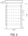
FIG. 2 is a plan view of a support portion as viewed from above. -
FIG. 3 is a side view when a carriage stands by at a first position in unidirectional printing in which printing is performed on an outward path. -
FIG. 4 is a side view when the printing is being performed in the unidirectional printing in which the printing is performed on the outward path. -
FIG. 5 is a side view of a state after the printing in the unidirectional printing in which the printing is performed on the outward path. -
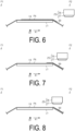
FIG. 6 is a side view when the carriage is positioned at a second position in the unidirectional printing in which the printing is performed on the outward path. -
FIG. 7 is a side view when the carriage starts to move from the second position in the unidirectional printing in which the printing is performed on the outward path. -
FIG. 8 is a side view when the carriage returns from the second position to the first position in the unidirectional printing in which the printing is performed on the outward path. -
FIG. 9 is a side view when the carriage stands by at the second position in unidirectional printing in which the printing is performed on a return path. -
FIG. 10 is a side view when the printing is being performed in the unidirectional printing in which the printing is performed on the return path. -
FIG. 11 is a side view of a state after the printing in the unidirectional printing in which the printing is performed on the return path. -
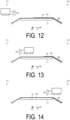
FIG. 12 is a side view when the carriage is positioned at the first position in the unidirectional printing in which the printing is performed on the return path. -
FIG. 13 is a side view when the carriage starts to move from the first position in the unidirectional printing in which the printing is performed on the return path. -
FIG. 14 is a side view when the carriage returns from the first position to the second position in the unidirectional printing in which the printing is performed on the return path. -
FIG. 15 is a plan view illustrating a modified example of the printing apparatus. -
FIG. 16 is a plan view illustrating a modified example different from the modified example illustrated inFIG. 15 . - An exemplary embodiment of a printing apparatus will be described below with reference to the accompanying drawings. The printing apparatus is, for example, an ink jet-type printer that prints an image of characters, photographs, and the like on a medium such as a sheet and fabric by discharging ink, which is an example of a liquid. The printing apparatus is, for example, a label printer.
- As illustrated in
FIG. 1 , aprinting apparatus 11 includes ahousing 12. - The
printing apparatus 11 includes afeeding unit 13 that feeds amedium 99. Thefeeding unit 13 is configured to feed themedium 99. Thefeeding unit 13 is accommodated in thehousing 12, for example. Thefeeding unit 13 includes afeeding shaft 14. Thefeeding shaft 14 rotatably holds aroll body 100 around which themedium 99 is wound. Thefeeding shaft 14 holds themedium 99 before printing. As thefeeding shaft 14 rotates, themedium 99 is fed from thefeeding unit 13. Thefeeding shaft 14 may be driven to rotate by a motor, or may be driven to rotate as a result of themedium 99 being pulled. - The
printing apparatus 11 includes awinding unit 15. Thewinding unit 15 is configured to take up themedium 99. Thewinding unit 15 is accommodated in thehousing 22, for example. Thewinding unit 15 includes awinding shaft 16. Similarly to thefeeding shaft 14, thewinding shaft 16 rotatably holds theroll body 100. Thewinding shaft 16 holds themedium 99 after the printing. As thewinding shaft 16 rotates, thewinding unit 15 takes up themedium 99. The windingshaft 16 is driven to rotate by a motor, for example. - The
printing apparatus 11 includes asupport portion 17. Thesupport portion 17 supports themedium 99. Thesupport portion 17 is accommodated in thehousing 12, for example. Thesupport portion 17 support themedium 99 from below, for example. Thesupport portion 17 supports themedium 99 in a process from when themedium 99 is fed from thefeeding unit 13 until when themedium 99 is taken up by thewinding unit 15. - As illustrated in
FIG. 2 , thesupport portion 17 includes asupport face 18. Thesupport face 18 is a surface that comes into contact with themedium 99 at thesupport portion 17. Thesupport face 18 faces upward at thesupport portion 17, for example. When thesupport portion 17 is viewed from a position facing thesupport face 18, that is, when thesupport portion 17 is viewed from above, the support face 18 overlaps with themedium 99. - Of the
medium 99, a region supported by thesupport portion 17 is a printing region PA. In theprinting apparatus 11, the printing is performed on the printing region PA of themedium 99. The printing region PA is a region, of themedium 99, that overlaps with thesupport portion 17 when thesupport portion 17 is viewed from a position facing thesupport face 18. In other words, when thesupport portion 17 is viewed in plan view, the printing region PA overlaps with thesupport face 18. The printing region PA is, for example, the entire region of the medium 99 supported by thesupport portion 17. The printing region PA is not limited to the entire region of the medium 99 supported by thesupport portion 17, but may be a portion of the region supported by thesupport portion 17. The printing region PA refers to the maximum region on which theprinting apparatus 11 can perform the printing, of the region supported by thesupport portion 17. - The
support portion 17 includes one or a plurality of through-holes 19. The through-hole 19 opens to thesupport face 18. The through-hole 19 is covered by the medium 99 positioned on thesupport face 18, for example. - As illustrated in
FIG. 1 , theprinting apparatus 11 includes a suckingunit 21. The suckingunit 21 is configured to cause the medium 99 to be sucked to thesupport portion 17. The suckingunit 21 sucks the medium 99 against thesupport portion 17, for example, by suctioning the medium 99 through thesupport portion 17. The suckingunit 21 includes a suction pump, for example. The suckingunit 21 suctions the medium 99 through the through-hole 19. As a result, the medium 99 is sucked to thesupport face 18. The suckingunit 21 may cause the medium 99 to be sucked to thesupport portion 17 by generating static electricity, for example. - The sucking
unit 21 can change the sucking force thereof, for example, by controlling the suction force. The suckingunit 21 changes the sucking force, for example, in accordance with the transport of the medium 99. For example, when the medium 99 is being transported, the sucking force of the suckingunit 21 is reduced compared to when the transport of the medium 99 is stopped. When the medium 99 is being transported, the suckingunit 21 causes the sucking force thereof to be relatively small. By causing the sucking force of the suckingunit 21 to be relatively small when the medium 99 is being transported, the medium 99 can easily move on thesupport portion 17. When the printing is performed on the medium 99, that is, when the transport of the medium 99 is stopped, the suckingunit 21 causes the sucking force thereof to be relatively large. By causing the sucking force of the suckingunit 21 to be relatively large when the transport of the medium 99 is stopped, the position of the medium 99 is less likely to be displaced on thesupport portion 17. - The
printing apparatus 12 includes atransport unit 22. Thetransport unit 22 is configured to transport the medium 99. Thetransport unit 22 is accommodated in thehousing 12, for example. Thetransport unit 22 transports the medium 99 from thefeeding unit 13 toward the windingunit 15. Thetransport unit 22 transports the medium 99 on thesupport portion 17 in a transport direction A1. The transport direction A1 indicates a direction in which the medium 99 moves on thesupport portion 17. - The
transport unit 22 transports a portion, of the medium 99, that has passed over thesupport portion 17 toward below thesupport portion 17. In other words, the printedmedium 99 is transported by thetransport unit 22 from thesupport portion 17 toward below thesupport portion 17. - The
transport unit 22 transports the medium 99 intermittently. In other words, thetransport unit 22 repeatedly starts and stops the transport. Thetransport unit 22 stops the transport of the medium 99, when the printing on the medium 99 is being performed. Thetransport unit 22 starts the transport of the medium 99, when the printing on the medium 99 is not being performed, for example, when the printing on the medium 99 is completed. In theprinting apparatus 11, the printing of the medium 99 and the transport of the medium 99 are alternately repeated. Note that, here, the completion of the printing on the medium 99 refers to a timing at which the printing is completed during a period in which the medium 99 is stopped between two transport cycles in the intermittent transport of the medium 99, on a region on which aprinting unit 25, which will be described below, is to perform the printing. - The
transport unit 22 includes at least onetransport roller 23. Thetransport roller 23 is positioned in thehousing 12, for example. Thetransport roller 23 rotates and thus transports the medium 99. The medium 99 is wound over thetransport roller 23. Thetransport rollers 23 may sandwich the medium 99. The medium 99 is transported as a result of thetransport roller 23 rotating. Thetransport roller 23 includes a roller that is driven to rotate by a motor, for example. Thetransport roller 23 is positioned below thesupport face 18, for example. - The
printing apparatus 11 includes a dryingunit 24. The dryingunit 24 is configured to dry the medium 99 on which the printing has been already performed. The dryingunit 24 dries the medium 99 in a process of the medium 99 being transported from thesupport portion 17 to the windingunit 15. The dryingunit 24 is positioned in thehousing 12, for example. The dryingunit 24 is positioned directly below thesupport portion 17, for example. The dryingunit 24 includes a heater that heats the medium 99, for example. The dryingunit 24 may include a fan that blows gas onto the medium 99. In this way, the dryingunit 24 dries the medium 99. - The
printing apparatus 11 includes theprinting unit 25. Theprinting unit 25 is configured to perform the printing on the medium 99. Theprinting unit 25 performs the printing on the medium 99 by discharging a liquid onto the medium 99. Theprinting unit 25 performs the printing on the printing region PA. Theprinting unit 25 is accommodated in thehousing 12, for example. Theprinting unit 25 includes acarriage 26 and ahead 27. Thecarriage 26 and thehead 27 are positioned above thesupport portion 17, for example. - The
head 27 is mounted on thecarriage 26. Thecarriage 26 is configured to move relative to the medium 99. Thecarriage 26 moves relative to the printing region PA. Thecarriage 26 moves through a region facing thesupport portion 17. When thesupport portion 17 is viewed in plan view, thecarriage 26 moves so as to pass over the printing region PA. Thecarriage 26 moves through a region above thesupport portion 17, for example. - The
carriage 26 is configured to move in the transport direction A1, for example. Specifically, thecarriage 26 reciprocates in the transport direction A1. In other words, thecarriage 26 moves in the transport direction A1 and in the opposite direction thereto. Thus, thecarriage 26 moves in a direction in which the medium 99 moves on thesupport portion 17. Conversely, thetransport unit 22 transports the medium 99 on thesupport portion 17 in a direction in which thecarriage 26 moves. - The
carriage 26 may be configured to move in an intersecting direction B1. The intersecting direction B1 is a direction different from the transport direction A1. Specifically, the intersecting direction B1 is a direction intersecting the transport direction A1 in the plane along thesupport face 18. The intersecting direction B1 indicates the width direction of the medium 99 to be transported. - The
carriage 26 may be configured to move only in the transport direction A1, or may be configured to move in both the transport direction A1 and the intersecting direction B1. In other words, theprinting apparatus 11 is a so-called lateral printer. Thecarriage 26 may be configured to move only in the intersecting direction B1. In this case, theprinting apparatus 11 is a so-called serial printer. - In this example, the
carriage 26 moves at least in the transport direction A1. Thus, in this example, the intersecting direction B1 indicates a direction in which thecarriage 26 provides a line feed as opposed to a direction in which thecarriage 26 moves relative to the medium 99. In other words, the intersecting direction B1 indicates a direction in which thecarriage 26 or thehead 27 provides the line feed as opposed to a direction in which thehead 27 moves while discharging the liquid onto the medium 99. Thecarriage 26 or thehead 27 may move along outward and return paths in the intersecting direction B1. In other words, thecarriage 26 or thehead 27 may move to one side and to the other side, which is the opposite direction from the one side, in the intersecting direction B1, for example. - By the
carriage 26 moving, the position of thecarriage 26 is changed between a plurality of positions. For example, by thecarriage 26 moving in the transport direction A1, the position of thecarriage 26 is changed between a first position P1, a second position P2, and a home position P3. - The first position P1 and the second position P2 are positions through which the
carriage 26 passes during the printing. The first position P1 is a position upstream from thesupport portion 17 in the transport direction A1. The second position P2 is a position downstream from thesupport portion 17 in the transport direction A1. Thecarriage 26 reciprocates between the first position P1 and the second position P2 during the printing, for example. In a process of thecarriage 26 changing its position from the first position P1 to the second position P2, and in a process of thecarriage 26 changing its position from the second position P2 to the first position P1, thecarriage 26 passes over thesupport portion 17. - One of the first position P1 and the second position P2 is a start position that is a start position of the printing. The other of the first position P1 and the second position P2 is a return position that is a return position of the printing. The
carriage 26 stands by at the start position before the printing is started. When the printing is started, thecarriage 26 moves from the start position to the return position. When thecarriage 26 reaches the return position, thecarriage 26 turns back from the return position toward the start position. With respect to thecarriage 26, a movement from the start position side to the return position side may be referred to as an outward movement, and a movement from the return position side to the start position side may be referred to as a return movement. - The home position P3 is a position at which the
carriage 26 stands by. Thecarriage 26 normally stands by at the home position P3. For example, when theprinting unit 25 is not performing the printing on the medium 99, thecarriage 26 is positioned at the home position P3. The home position P3 is, for example, a position upstream from thesupport portion 17 in the transport direction A1. Specifically, the home position P3 is a position upstream from the first position P1 in the transport direction A1. Thecarriage 26 moves from the home position P3 to the start position before the printing is started. - The
head 27 includes at least one nozzle. Thehead 27 discharges the liquid from the nozzle. Thehead 27 discharges the liquid onto the medium 99 supported by thesupport portion 17. Specifically, thehead 27 discharges the liquid onto the printing region PA. Thehead 27 discharges the liquid onto the medium 99 while the transport of the medium 99 by thetransport unit 22 is stopped. As a result, an image is printed on the medium 99. - The
head 27 moves relative to thesupport portion 17 together with thecarriage 26. Thehead 27 discharges the liquid onto the medium 99 while moving together with thecarriage 26. Specifically, thehead 27 discharges the liquid onto the medium 99 while moving together with thecarriage 26 in one direction. Thehead 27 discharges the liquid onto the medium 99, for example, while moving together with thecarriage 26 in the transport direction A1 or in the opposite direction thereto. When theprinting apparatus 11 is a serial printer, thehead 27 discharges the liquid onto the medium 99 while moving together with thecarriage 26 in the intersecting direction B1 or in the opposite direction thereto. - The width of the
head 27 is the same as the width of the medium 99, or longer than the width of the medium 99, for example. In other words, thehead 27 is, for example, a line head capable of simultaneously discharging the liquid across the entire width of the medium 99. As a result, thehead 27 can discharge the liquid onto the entire region of the printing region PA simply by moving together with thecarriage 26 once in the transport direction A1 or in the opposite direction thereto. In other words, thehead 27 can perform the printing on the entire region of the printing region PA without causing thecarriage 26 to move in the intersecting direction B1. - The width of the
head 27 may be shorter than the width of the medium 99. In this case, thehead 27 discharge the liquid across the entire width of the medium 99 by moving in both the transport direction A1 and the intersecting direction B1. Thehead 27 performs the printing across the entire width of the medium, for example, by repeating the movement accompanied by the discharge of the liquid, and the provision of the line feed, that is, by alternately repeating the movement in the transport direction A1 and the movement in the intersecting direction B1. Thus, in this case, thehead 27 performs the printing on the entire region of the printing region PA, by thecarriage 26 reciprocating in the transport direction A1 and providing the line feed in the intersecting direction B1. - The
printing unit 25 performs the printing with a predetermined number of passes. The number of passes refers to a number of times thehead 27 moves in order to complete the printing on a predetermined region. The number of passes is, for example, the number of movements of thecarriage 26 accompanied by the discharge of the liquid by thehead 27. Theprinting unit 25 performs the printing on the printing region PA in a single pass, for example. In this case, the printing by thehead 27 is completed by thecarriage 26 passing over the printing region PA once. Theprinting unit 25 may perform the printing on the printing region PA in multiple passes. In this case, the printing by thehead 27 is completed by thecarriage 26 passing over the printing region PA a plurality of times. - The
printing unit 25 performs unidirectional printing on the medium 99, for example. The unidirectional printing is a printing method in which the movement direction of thecarriage 26 accompanied by the discharge of the liquid onto the medium 99 is a single direction. In the unidirectional printing, theprinting unit 25 discharges the liquid onto the medium 99 as theprinting unit 25 moves in the transport direction A1 or in the opposite direction thereto. In other words, the unidirectional printing is a printing method in which the discharge of the liquid by thehead 27 is performed while thecarriage 26 is moving on the outward path or on the return path, when thecarriage 26 reciprocates relative to the medium 99. - The
printing unit 25 may perform bidirectional printing on the medium 99. The bidirectional printing is a printing method in which a movement direction of thecarriage 26 accompanied by the discharge of the liquid onto the medium 99 is a plurality of directions. In the bidirectional printing, theprinting unit 25 discharges the liquid as theprinting unit 25 moves in the transport direction A1 and the opposite direction thereto, for example. In other words, the bidirectional printing is a printing method in which the discharge of the liquid by thehead 27 is performed while thecarriage 26 is moving on both the outward path and on the return path when thecarriage 26 reciprocates relative to the medium 99. - The
printing apparatus 11 includes acontrol unit 28. Thecontrol unit 28 comprehensively controls theprinting apparatus 11. Thecontrol unit 28 controls the suckingunit 21, thetransport unit 22, theprinting unit 25, and the like, for example. Thecontrol unit 28 controls the transport of the medium 99 and the printing on the medium 99. Thecontrol unit 28 alternately executes the transport of the medium 99 and the printing on the medium 99. - The
control unit 28 may be constituted by one or a plurality of processors that are configured to execute various types of processing in accordance with a computer program. Thecontrol unit 28 may be constituted by one or a plurality of dedicated hardware circuits, such as application specific integrated circuits, that are configured to execute at least a portion of various types of processing. Thecontrol unit 28 may be constituted by a circuit including a combination of a processor and a hardware circuit. The processor includes a CPU and a memory such as a RAM and a ROM. The memory stores program codes or commands configured to cause the CPU to execute processing. The memory, that is, a computer-readable medium, includes any readable medium that can be accessed by a general purpose or special purpose computer. - The
control unit 28 controls thetransport unit 22 in order to control the starting and stopping of the transport. As a result, thetransport unit 22 controls the transport timing of the medium 99. Thecontrol unit 28 controls theprinting unit 25 to control the starting and stopping of the movement by thecarriage 26. Thecontrol unit 28 controls theprinting unit 25 to control the discharge of the liquid by thehead 27 in accordance with the movement of thecarriage 26. In other words, thecontrol unit 28 controls the movement timing of thecarriage 26 and the discharge timing of thehead 27. - Next, with respect to the unidirectional printing, a case where the printing is performed on the outward path, and a case where the printing is performed on the return path will be described. The
control unit 28 performs the unidirectional printing on the medium 99 by controlling thetransport unit 22, thecarriage 26, and thehead 27. First, the case where the printing is performed on the outward path is described. Here, when thecarriage 26 moves on the outward path, thecontrol unit 28 causes thehead 27 to discharge the liquid. - As illustrated in
FIG. 3 , before the printing is started, thecontrol unit 28 causes thecarriage 26 to stand by at the start position, for example, at the first position P1. After that, thecontrol unit 28 moves thecarriage 26 from the start position to the return position. In other words, thecontrol unit 28 moves thecarriage 26 from the first position P1 to the second position P2. As a result, thecarriage 26 and thehead 27 move on the outward path. At this time, thecontrol unit 28 starts the movement of thecarriage 26 in a state in which the medium 99 is stopped. - As illustrated in
FIG. 4 , thecontrol unit 28 causes thehead 27 to discharge the liquid as thecarriage 26 moves over the printing area PA. As a result, an image is printed on the printing region PA. Thecontrol unit 28 causes thehead 27 to discharge the liquid while moving thecarriage 26 relative to the printing region PA. - As illustrated in
FIG. 5 andFIG. 6 , thecontrol unit 28 starts the transport of the medium 99 by thetransport unit 22 after the discharge of the liquid by thehead 27 is completed and before thecarriage 26 stops. Thecontrol unit 28 starts the transport of the medium 99 by thetransport unit 22, for example, after the discharge of the liquid by thehead 27 is completed, and before thecarriage 26 reaches the second position P2. In other words, thecontrol unit 28 executes the movement of thecarriage 26 in parallel with the transport of the medium 99. At this time, while thecarriage 26 moves in the transport direction A1, the medium 99 moves in the transport direction A1. As a result, productivity of theprinting apparatus 11 is improved compared to a case where the transport of the medium 99 is started after thecarriage 26 stops. Thecontrol unit 28 improves the productivity of theprinting apparatus 11 by causing the movement period of thecarriage 26 and the transport period of the medium 99 to coincide with each other. - The
control unit 28 may start the transport of the medium 99 by thetransport unit 22, for example, after thehead 27 has passed over the printing region PA and before thecarriage 26 stops. Specifically, thecontrol unit 28 may start the transport of the medium 99 by thetransport unit 22 after a state is obtained in which thehead 27 no longer overlaps with the printing region PA when thesupport portion 17 is viewed in plan view, and before thecarriage 26 reaches the second position P2. - When the transport of the medium 99 is started immediately after the printing is completed, the medium 99 may be transported in a state in which the
head 27 is positioned over thesupport portion 17. In other words, the medium 99 may be transported in a state in which thehead 27 overlaps with the printing region PA. In this case, thehead 27 may come into contact with the medium 99. Particularly, since the sucking force of the suckingunit 21 is reduced when the medium 99 is being transported, the medium 99 is more likely to be lifted from thesupport portion 17. Further, a portion, of the medium 99, onto which the liquid has been discharged swells. Thus, if the transport of the medium 99 is started in the state in which thehead 27 overlaps with the printing region PA, a printed portion of the medium 99 is more likely to come into contact with thehead 27. In contrast, by starting the transport of the medium 99 after the head has passed over thesupport portion 17, the risk of the printed portion of the medium 99 coming into contact with thehead 27 is reduced. - The
control unit 28 may start the transport of the medium 99 by thetransport unit 22, for example, after the liquid last discharged from thehead 27 has landed on the medium 99 and before thecarriage 26 stops. For example, by counting the time elapsed from when the liquid was discharged from thehead 27, thecontrol unit 28 detects the landing of the liquid on the medium 99. Therefore, thecontrol unit 28 may start the transport of the medium 99 by thetransport unit 22 after a predetermined time period has elapsed from when the liquid was last discharged from thehead 27, and before thecarriage 26 stops. If the transport of the medium 99 by thetransport unit 22 is started before the liquid discharged from thehead 27 lands on the medium 99, the landing position of the liquid may be displaced. In contrast, by starting the transport of the medium 99 after the liquid last discharged from thehead 27 has landed on the medium 99, the productivity of theprinting apparatus 11 is improved while suppressing deterioration in the printing quality. Furthermore, the transport of the medium 99 by thetransport unit 22 may be started after the liquid last discharged from thehead 27 has landed on the medium 99, after thehead 27 has passed over the landing position of the liquid last discharged from thehead 27, and before thecarriage 26 stops. In this way, in addition to the effect described above, the risk of the printedmedium 99 coming into contact with thehead 27 is reduced. - The liquid last discharged from the
head 27 refers to the liquid discharged by thehead 27 immediately before the transport of the medium 99 is started. In theprinting apparatus 11, the transport of the medium 99 and the printing on the medium 99 are alternately executed. Thus, the discharge of the liquid executed immediately before the transport of the medium 99 is started is the last discharge of the liquid, in one print cycle. - The
control unit 28 may start the transport of the medium 99 by thetransport unit 22 after thehead 27 has passed over the image printed on the medium 99 and before thecarriage 26 stops. Specifically, thecontrol unit 28 may start the transport of the medium 99 by thetransport unit 22 after a state is obtained in which thehead 27 no longer overlaps with the image printed on the medium 99 when thesupport portion 17 is viewed in plan view, and before thecarriage 26 stops. In this way, for example, when the printing is performed only on a portion of the printing region PA, the timing of starting the transport of the medium 99 can be brought forward compared to a case where the transport of the medium 99 by thetransport unit 22 is started after thehead 27 has passed over the printing region PA. Therefore, the productivity of theprinting apparatus 11 is improved. - As illustrated in
FIG. 6 , thecontrol unit 28 stops thecarriage 26 at the return position. Specifically, thecontrol unit 28 stops thecarriage 26 that has reached the second position P2. At this time, the transport of the medium 99 is continued. Since the medium 99 is transported toward below thesupport portion 17, the medium 99 is less likely to come into contact with thehead 27, which has passed over the printing region PA. - As illustrated in
FIG. 7 , thecontrol unit 28 starts the movement of thecarriage 26 positioned at the return position, for example, at the second position P2. Specifically, thecontrol unit 28 returns thecarriage 26 from the return position to the start position. In other words, thecontrol unit 28 moves thecarriage 26 from the second position P2 to the first position P1. As a result, thecarriage 26 and thehead 27 move on the return path. - The
control unit 28 starts the movement of thecarriage 26 before the transport of the medium 99 by thetransport unit 22 is completed. In other words, thecontrol unit 28 starts the movement of thecarriage 26 in a state in which the medium 99 is being transported. Thecontrol unit 28 executes the movement of thecarriage 26 in parallel with the transport of the medium 99. At this time, while the medium 99 moves in the transport direction A1, thecarriage 26 moves in the direction opposite to the transport direction A1. As a result, the productivity of theprinting apparatus 11 is improved compared to a case where the movement of thecarriage 26 is started after the transport of the medium 99 is completed. Thecontrol unit 28 improves the productivity of theprinting apparatus 11 by causing the movement period of thecarriage 26 and the transport period of the medium 99 to coincide with each other. - As illustrated in
FIG. 7 and FIG. 8 , thecontrol unit 28 moves thecarriage 26 so that the image printed on the medium 99 and thehead 27 do not overlap with each other over thesupport portion 17 when thesupport portion 17 is viewed in plan view. Thecontrol unit 28 starts the movement of thecarriage 26 so that the printed portion of the medium 99 has passed over thesupport portion 17 by the time when thehead 27 reaches thesupport portion 17. Thecontrol unit 28 controls the timing of starting the movement of thecarriage 26, for example, based on the time elapsed from when the transport of the medium 99 was started, or the rotation amount of thetransport roller 23. Thecontrol unit 28 starts the movement of thecarriage 26 after a predetermined time period has elapsed from when the transport of the medium 99 was started, or after the medium 99 has been transported by a predetermined amount. - As illustrated in
FIG. 8 , thecontrol unit 28 stops transporting the medium 99 after the printed portion of the medium 99 has passed over thesupport portion 17. At this time, the movement of thecarriage 26 is continued. After thecarriage 26 has reached the start position, thecontrol unit 28 starts the printing on the next printing region PA. In other words, thecontrol unit 28 starts the discharge of the liquid by thehead 27 after the transport of the medium 99 by thetransport unit 22 is completed. In the bidirectional printing, thecontrol unit 28 performs the printing on the next printing region PA in the course of thecarriage 26 returning from the return position to the start position. - Next, the case where the printing is performed on the return path will be described. Here, the
control unit 28 causes thehead 27 to discharge the liquid when thecarriage 26 moves on the return path. - As illustrated in
FIG. 9 , before the printing is started, thecontrol unit 28 causes thecarriage 26 to stand by at the start position, for example, at the second position P2. After that, thecontrol unit 28 moves thecarriage 26 from the start position to the return position. In other words, thecontrol unit 28 moves thecarriage 26 from the second position P2 to the first position P1. As a result, thecarriage 26 and thehead 27 move on the return path. At this time, thecontrol unit 28 starts the movement of thecarriage 26 in a state in which the medium 99 is stopped. - As illustrated in
FIG. 10 , thecontrol unit 28 causes thehead 27 to discharge the liquid as thecarriage 26 moves over the printing area PA. As a result, an image is printed on the printing region PA. Thecontrol unit 28 causes thehead 27 to discharge the liquid while moving thecarriage 26 relative to the printing region PA. - As illustrated in
FIG. 11 andFIG. 12 , thecontrol unit 28 starts the transport of the medium 99 by thetransport unit 22 after the discharge of the liquid by thehead 27 is completed and before thecarriage 26 stops. Thecontrol unit 28 starts the transport of the medium 99 by thetransport unit 22, for example, after the discharge of the liquid by thehead 27 is completed, and before thecarriage 26 reaches the first position P1. In other words, thecontrol unit 28 executes the movement of thecarriage 26 in parallel with the transport of the medium 99. At this time, while thecarriage 26 moves in the opposite direction to the transport direction A1, the medium 99 moves in the transport direction A1. As a result, productivity of theprinting apparatus 11 is improved compared to a case where the transport of the medium 99 is started after thecarriage 26 stops. Thecontrol unit 28 improves the productivity of theprinting apparatus 11 by causing the movement period of thecarriage 26 and the transport period of the medium 99 to coincide with each other. - The
control unit 28 may start the transport of the medium 99 by thetransport unit 22, for example, after thehead 27 has passed over the printing region PA and before thecarriage 26 stops. Specifically, thecontrol unit 28 may start the transport of the medium 99 by thetransport unit 22 after the state is obtained in which thehead 27 no longer overlaps with the printing region PA when thesupport portion 17 is viewed in plan view, and before thecarriage 26 reaches the first position P1. By starting the transport of the medium 99 after the head has passed over thesupport portion 17, the risk of the printed portion of the medium 99 coming into contact with thehead 27 is reduced. - The
control unit 28 may start the transport of the medium 99 by thetransport unit 22, for example, after the liquid last discharged from thehead 27 has landed on the medium 99 and before thecarriage 26 stops. By starting the transport of the medium 99 after the liquid last discharged from thehead 27 has landed on the medium 99, the productivity of theprinting apparatus 11 is improved while suppressing the deterioration in the printing quality. - The
control unit 28 may start the transport of the medium 99 by thetransport unit 22 after thehead 27 has passed over the image printed on the medium 99 and before thecarriage 26 stops. Specifically, thecontrol unit 28 may start the transport of the medium 99 by thetransport unit 22 after a state is obtained in which thehead 27 no longer overlaps with the image printed on the medium 99 when thesupport portion 17 is viewed in plan view, and before thecarriage 26 stops. In this way, for example, when the printing is performed only on a portion of the printing region PA, the timing of starting the transport of the medium 99 can be brought forward compared to a case where the transport of the medium 99 by thetransport unit 22 is started after thehead 27 has passed over the printing region PA. Therefore, the productivity of theprinting apparatus 11 is improved. - As illustrated in
FIG. 12 , thecontrol unit 28 stops thecarriage 26 at the return position. Specifically, thecontrol unit 28 stops thecarriage 26 that has reached the first position P1. At this time, the transport of the medium 99 is continued. Since the medium 99 is transported toward thesupport portion 17 from below thesupport portion 17, the medium 99 is less likely to come into contact with thehead 27, which has passed over the printing region PA. - As illustrated in
FIG. 13 , thecontrol unit 28 starts the movement of thecarriage 26 positioned at the return position, for example, at the first position P1. Specifically, thecontrol unit 28 returns thecarriage 26 from the return position to the start position. In other words, thecontrol unit 28 moves thecarriage 26 from the first position P1 to the second position P2. As a result, thecarriage 26 and thehead 27 move on the outward path. - The
control unit 28 starts the movement of thecarriage 26 before the transport of the medium 99 by thetransport unit 22 is completed. In other words, thecontrol unit 28 starts the movement of thecarriage 26 in a state in which the medium 99 is being transported. Thecontrol unit 28 executes the movement of thecarriage 26 in parallel with the transport of the medium 99. At this time, while the medium 99 moves in the transport direction A1, thecarriage 26 moves in the transport direction A1. As a result, the productivity of theprinting apparatus 11 is improved compared to the case where the movement of thecarriage 26 is started after the transport of the medium 99 is completed. Thecontrol unit 28 improves the productivity of theprinting apparatus 11 by causing the movement period of thecarriage 26 and the transport period of the medium 99 to coincide with each other. - The
control unit 28 moves thecarriage 26 so that the image printed on the medium 99 and thehead 27 do not overlap with each other over thesupport portion 17 when thesupport portion 17 is viewed in plan view. Thecontrol unit 28 moves thecarriage 26 so that thehead 27 does not catch up with the printed portion of the medium 99. This is because, when thehead 27 catches up with the printed portion of the medium 99, thehead 27 may come into contact with the printed portion. Thecontrol unit 28 moves thecarriage 26 so that the printed portion of the medium 99 and thehead 27 do not overlap with each other over the support portion 178, for example, by controlling the timing of starting the movement of thecarriage 26, or by controlling the movement velocity of thecarriage 26. - As illustrated in
FIG. 14 , thecontrol unit 28 stops the transport of the medium 99 after the printed portion of the medium 99 has passed over thesupport portion 17. At this time, the movement of thecarriage 26 is continued. After thecarriage 26 has reached the start position, thecontrol unit 28 starts the printing on the next printing region PA. In other words, thecontrol unit 28 starts the discharge of the liquid by thehead 27 after the transport of the medium 99 by thetransport unit 22 is completed. In the bidirectional printing, thecontrol unit 28 performs the printing on the next printing region PA during a period in which thecarriage 26 returns from the return position to the start position. - Next, operations and effects of the exemplary embodiment described above will be described.
- (1) The
control unit 28 causes thehead 27 to discharges the liquid while moving thecarriage 26 relative to the printing region PA. Thecontrol unit 28 starts the transport of the medium 99 by thetransport unit 22 after the discharge of the liquid by thehead 27 is completed and before thecarriage 26 stops. According to the configuration described above, the productivity of theprinting apparatus 11 is improved compared to the case where the transport of the medium 99 by thetransport unit 22 is started after thecarriage 26 stops. - (2) The
control unit 28 starts the movement of thecarriage 26 before the transport of the medium 99 by thetransport unit 22 is completed. Thecontrol unit 28 starts the discharge of the liquid by thehead 27 after the transport of the medium 99 by thetransport unit 22 is completed. According to the configuration described above, the productivity of theprinting apparatus 11 is improved compared to the case where the movement of thecarriage 26 is started after the transport of the medium 99 by thetransport unit 22 is completed. - (3) The
control unit 28 moves thecarriage 26 so that the image printed on the medium 99 and thehead 27 do not overlap with each other over thesupport portion 17 when thesupport portion 17 is viewed from a position facing thesupport portion 17.
The medium 99 may swell as a result of the liquid being discharged onto the medium 99. When the medium 99 swells, the medium 99 and thehead 27 are more likely to come into contact with each other. According to the configuration described above, since thecarriage 26 moves so that the image printed on the medium 99 and thehead 27 do not overlap with each other over thesupport portion 17, the risk of thehead 27 coming into contact with the medium 99 is reduced. - (4) The
control unit 28 performs the unidirectional printing on the medium 99 by controlling thehead 27 and thecarriage 26. Thecontrol unit 28 causes thehead 27 to discharge the liquid when thecarriage 26 moves on the outward path. According to the configuration described above, when thehead 27 discharges the liquid on the outward path in the unidirectional printing, the productivity of theprinting apparatus 11 is improved. - (5) The
control unit 28 performs the unidirectional printing on the medium 99 by controlling thehead 27 and thecarriage 26. Thecontrol unit 28 causes thehead 27 to discharge the liquid when thecarriage 26 moves on the return path. According to the configuration described above, when thehead 27 discharges the liquid on the return path in the unidirectional printing, the productivity of theprinting apparatus 11 is improved. - (6) The
transport unit 22 transports the medium 99 in the direction in which thecarriage 26 moves over thesupport portion 17. Thetransport unit 22 transports a portion, of the medium 99, that has passed over thesupport portion 17 toward below thesupport portion 17.
According to the configuration described above, the printed portion of the medium 99 is transported so as to be below thesupport portion 17. As a result, the risk of the image printed on the medium 99 coming into contact with thehead 27 is reduced. - (7) The
head 27 is a line head capable of simultaneously discharging the liquid across the entire width of the medium 99, and performs the printing on the printing region PA in a single pass. According to the configuration described above, the productivity of theprinting apparatus 11 is improved compared to a case where thehead 27 performs the printing in multiple passes. - (8) The
control unit 28 starts the transport of the medium 99 by thetransport unit 22 after thehead 27 has passed over the printing region PA and before thecarriage 26 stops.
According to the configuration described above, since the transport of the medium 99 by thetransport unit 22 is started after thehead 27 has passed over the printing region PA, the risk of the image printed on the medium 99 coming into contact with thehead 27 is reduced. - (9) The
control unit 28 starts the transport of the medium 99 by thetransport unit 22 after the liquid last discharged from thehead 27 has landed on the medium 99 and before thecarriage 26 stops.
When the transport of the medium 99 by thetransport unit 22 is started before the liquid discharged from thehead 27 lands on the medium 99, the printing quality may deteriorate. In this regard, according to the configuration described above, the productivity of theprinting apparatus 11 is improved while suppressing the deterioration in the printing quality. - (10) The
control unit 28 starts the transport of the medium 99 by thetransport unit 22 after the discharge of the liquid by thehead 27 is completed, after thehead 27 has passed over the image printed on the medium 99, and before thecarriage 26 stops. - According to the configuration described above, for example, when the printing is performed only on a portion of the printing region PA, the timing of starting the transport of the medium 99 can be brought forward compared to the case where the transport of the medium 99 by the
transport unit 22 is started after thehead 27 has passed over the printing region PA. As a result, the productivity of theprinting apparatus 11 is improved. - This exemplary embodiment can be modified and implemented as described below. This exemplary embodiment and modified examples described below can be combined and implemented within a range in which a technical contradiction does not arise.
- As illustrated in
FIG. 15 , theprinting unit 25 may perform the printing on the printing region PA by moving in the transport direction A1 and the intersecting direction B1. In this modified example, the width of thehead 27 is shorter than the width of the medium 99. Theprinting unit 25 performs the printing on the printing region PA, for example, by repeating the movement in the transport direction A1 and the provision of the line feed in the intersecting direction B1. - The
carriage 26 moves in the transport direction A1 relative to the medium 99 a plurality of times in the one print cycle. Thecarriage 26 moves from the first position P1, which is the start position, to the second position P2, which is the end position, by repeating the movement in the transport direction A1 and the movement in the intersecting direction B1. The end position is a position at which thecarriage 26 is ultimately positioned when the one print cycle is completed. The end position is positioned upstream from thesupport portion 17 in the transport direction A1, for example. The end position is a position different from the start position in the intersecting direction B1. - The
head 27 discharges the liquid when thehead 27 moves together with thecarriage 26 in the transport direction A1 or in the opposite direction thereto. Thehead 27 performs the printing on the medium 99 by moving in the transport direction A1 a plurality of times while shifting its position in the intersecting direction B1. In the example illustrated inFIG. 15 , theprinting apparatus 11 performs the printing on a region corresponding to one raster on the medium 99 in a single pass, using the unidirectional printing method. Here, the region corresponding to one raster is a region in which thehead 27 and the medium 99 overlap with each other when thehead 27 is moved once in the transport direction A1. When the printing is performed on the region corresponding to one raster in multiple passes, the movement amount of thecarriage 26 moving in the intersecting direction B1 decreases, and the number of movements of thecarriage 26 increases. Thecarriage 26 may move in the intersecting direction B1 after completing its movement on the outward path in the transport direction A1, or may move in the intersecting direction B1 after completing its movement on the return path in the transport direction A1. Theprinting apparatus 11 may perform the bidirectional printing on the medium 99. - The
control unit 28 starts the transport of the medium 99 by thetransport unit 22 after thehead 27 has completed the printing and before thecarriage 26 reaches the end position. In this modified example, at the time at which the printing by thehead 27 is completed, thecarriage 26 has already made the last movement in the direction parallel to the transport direction A1. Therefore, thecontrol unit 28 starts the transport of the medium 99 by thetransport unit 22 after thehead 27, which is moving together with thecarriage 26 in the last movement, has passed over the printing region PA, and before thecarriage 26 reaches the end position. - The
control unit 28 starts the movement of thecarriage 26 before the transport of the medium 99 by thetransport unit 22 is completed. Thecontrol unit 28 moves thecarriage 26 positioned at the end position, before the transport of the medium 99 by thetransport unit 22 is completed. For example, after thecarriage 26 reaches the end position, thecontrol unit 28 moves thecarriage 26 in the opposite direction to the intersecting direction B1, while the medium 99 is being transported. As a result, thecarriage 26 returns to the start position. - As illustrated in
FIG. 16 , theprinting apparatus 11 may be a serial printer. In this modified example, theprinting unit 25 performs the printing on the printing region PA by moving in the intersecting direction B1. Specifically, theprinting unit 25 performs the printing on the printing region PA by reciprocating in the intersecting direction B1. - The
carriage 26 moves from the first position P1, which is the start position, to the second position P2, which is the end position, for example, by moving from one side to the other side in the intersecting direction B1. For example, thehead 27 discharges the liquid when moving to the one side in the intersecting direction B1 together with thecarriage 26, or when moving to the other side, which is in the opposite direction. In the example illustrated inFIG. 16 , theprinting apparatus 11 performs the printing on the medium 99 in a single pass, using the unidirectional printing method. When the printing is performed using multiple passes, the transport amount of the medium 99 by thetransport unit 22 each time the medium 99 is transported decreases, and the number of times the medium 99 is transported by thetransport unit 22 increases. As a result, the number of movements of thecarriage 26 increases. Theprinting apparatus 11 may perform the bidirectional printing on the medium 99. - The
control unit 28 starts the transport of the medium 99 by thetransport unit 22 after the printing by thehead 27 is completed and before thecarriage 26 stops. For example, the transport of the medium 99 by thetransport unit 22 is started after thehead 27, which is moving together with thecarriage 26 in the intersecting direction B1, has passed over the printing region PA, and before thecarriage 26 stops. - The
control unit 28 starts the movement of thecarriage 26 before the transport of the medium 99 by thetransport unit 22 is completed. Thecontrol unit 28 moves thecarriage 26 positioned at the return position before the transport of the medium 99 by thetransport unit 22 is completed. At this time, thecontrol unit 28 moves thecarriage 26 so that thehead 27 does not overlap with the image printed on the medium 99 over thesupport portion 17. For example, after thecarriage 26 reaches the return position, thecontrol unit 28 moves thecarriage 26 to the other side in the intersecting direction B1, in a state in which the medium 99 is being transported. At this time, thecontrol unit 28 starts the movement of thecarriage 26 so that, by the time when thehead 27 reaches thesupport portion 17, the medium 99 is transported by an amount equivalent to the length of thehead 27 in the transport direction A1. As a result, thehead 27, which is moving together with thecarriage 26 to the other side in the intersecting direction B1, does not overlap with the printed portion of the medium 99 over thesupport portion 17. - When transporting the medium 99 before the printing is started, the
control unit 28 may move thecarriage 26 before the transport of the medium 99 is completed. For example, after the transport of the medium 99 is completed, thecontrol unit 28 starts the discharge of the liquid by thehead 27 while continuing to move thecarriage 26. As a result, a time required before starting the printing is shortened compared to a case where the movement of thecarriage 26 is started after the transport of the medium 99 is completed. Therefore, the productivity of theprinting apparatus 11 is improved. - The liquid discharged by the
head 27 is not limited to ink, and may be, for example, a liquid material including particles of a functional material dispersed or mixed in liquid. For example, thehead 27 may discharge a liquid material including a material such as an electrode material or a pixel material used in manufacturing a liquid crystal display, an electroluminescent (EL) display, a surface emitting display, and the like in a dispersed or dissolved form. - Technical ideas derived from the above-described exemplary embodiment and modified examples, and operations and advantages of the technical ideas will be described below.
- (A) A printing apparatus includes a transport unit configured to intermittently transport a medium, a support portion configured to support the medium, a head configured to perform printing by discharging a liquid onto the medium supported by the support portion, during a period in which the transport of the medium by the transport unit is stopped, a carriage at which the head is mounted and that is configured to move relative to the medium, and a control unit. The control unit causes the head to discharge the liquid onto a printing region while moving the carriage, the printing region being a region, of the medium, supported by the support portion, and starts the transport of the medium by the transport unit after the discharge of the liquid by the head is completed and before the carriage stops.
According to the configuration described above, the printing speed is improved compared to a case where the transport of the medium by the transport unit is started after the discharge of the liquid by the head is completed and after thecarriage 26 stops. Therefore, productivity of the printing apparatus is improved. - (B) In the printing apparatus described above, the control unit may start the movement of the carriage before the transport of the medium by the transport unit is completed, and may start the discharge of the liquid by the head after the transport of the medium by the transport unit is completed. According to the configuration described above, the printing speed is improved compared to a case where the movement of the carriage is started after the transport of the medium by the transport unit is completed. Therefore, the productivity of the printing apparatus is improved.
- (C) In the printing apparatus described above, the control unit may move the carriage such that an image printed on the medium and the head do not overlap with each other above the support portion, when the support portion is viewed from a position facing the support portion.
The medium may swell as a result of the liquid being discharged onto the medium. When the medium swells, the medium and the head are more likely to come into contact with each other. According to the configuration described above, since the carriage moves so that the image printed on the medium and the head do not overlap with each other over the support portion, the risk of the head coming into contact with the medium is reduced. - (D) In the printing apparatus described above, the control unit may perform unidirectional printing on the medium by controlling the head and the carriage, and may cause the head to discharge the liquid when the carriage moves on an outward path. According to the configuration described above, when the head discharges the liquid on the outward path in the unidirectional printing, the productivity of the printing apparatus is improved.
- (E) In the printing apparatus described above, the control unit may perform unidirectional printing on the medium by controlling the head and the carriage, and may cause the head to discharge the liquid when the carriage moves on a return path. According to the configuration described above, when the head discharges the liquid on the return path in the unidirectional printing, the productivity of the printing apparatus is improved.
- (F) In the printing apparatus described above, the head and the carriage may be positioned above the support portion, and the transport unit may transport the medium on the support portion in a direction in which the carriage moves, and may transport a portion, of the medium, that passed over the support portion toward below the support portion. According to the configuration described above, the printed portion of the medium is transported so as to be below the support portion. As a result, the risk of the printed portion of the medium coming into contact with the head is reduced.
- (G) In the printing apparatus described above, the head may be a line head configured to simultaneously discharge the liquid across an entire width of the medium, and may perform the printing on the printing region in a single pass. According to the configuration described above, the productivity of the printing apparatus is improved compared to a case where the head performs the printing in multiple passes.
- (H) In the printing apparatus described above, the control unit may start the transport of the medium by the transport unit after the discharge of the liquid by the head is completed, after the head passed over the printing region, and before the carriage stops. According to the configuration described above, since the transport of the medium by the transport unit is started after the head has passed over the printing region, the risk of the printed portion of the medium coming into contact with the head is reduced.
- (I) In the printing apparatus described above, the control unit may start the transport of the medium by the transport unit after the discharge of the liquid by the head is completed, after the liquid last discharged by the head landed on the medium, and before the carriage stops.
When the transport of the medium by the transport unit is started before the liquid discharged from the head lands on the medium, the printing quality may deteriorate. In this regard, according to the configuration described above, the productivity of the printing apparatus is improved while suppressing the deterioration in the printing quality. - (J) In the printing apparatus described above, the control unit may start the transport of the medium by the transport unit after the discharge of the liquid by the head is completed, after the head passed over an image printed on the medium, and before the carriage stops.
According to the configuration described above, for example, when the printing is performed only on a portion of the printing region, the timing of starting the transport of the medium can be brought forward compared to a case where the transport of the medium by the transport unit is started after the head passed over the printing region. As a result, the productivity of the printing apparatus is improved. - (K) A method of printing includes causing a head to discharge a liquid onto a printing region while moving a carriage, the printing region being a region, of a medium, supported by a support portion, and starting transport of the medium by a transport unit after the discharge of the liquid by the head is completed and before the carriage stops. According to the configuration described above, the same effects as those of the printing apparatus described above can be obtained.
- (L) A printing apparatus includes a transport unit configured to intermittently transport a medium, a support portion configured to support the medium, a head configured to perform printing by discharging a liquid onto the medium supported by the support portion, during a period in which the transport of the medium by the transport unit is stopped, a carriage at which the head is mounted and that is configured to move relative to the medium, and a control unit. The control unit starts the movement of the carriage before the transport of the medium by the transport unit is completed, and starts the discharge of the liquid by the head after the transport of the medium by the transport unit is completed. According to the configuration described above, the printing speed is improved compared to a case where the movement of the carriage is started after the transport of the medium by the transport unit is completed. Therefore, the productivity of the printing apparatus is improved.
- (M) In the printing apparatus described above, the control unit may move the carriage such that an image printed on the medium and the head do not overlap with each other above the support portion, when the support portion is viewed from a position facing the support portion.
The medium may swell as a result of the liquid being discharged onto the medium. When the medium swells, the medium and the head are more likely to come into contact with each other. According to the configuration described above, since the carriage moves so that the image printed on the medium and the head do not overlap with each other over the support portion, the risk of the head coming into contact with the medium is reduced. - (N) In the printing apparatus described above, the control unit may perform unidirectional printing on the medium by controlling the head and the carriage, and may cause the head to discharge the liquid when the carriage moves on an outward path. According to the configuration described above, when the head discharges the liquid on the outward path in the unidirectional printing, the productivity of the printing apparatus is improved.
- (O) In the printing apparatus described above, the control unit may perform unidirectional printing on the medium by controlling the head and the carriage, and may cause the head to discharge the liquid when the carriage moves on a return path. According to the configuration described above, when the head discharges the liquid on the return path in the unidirectional printing, the productivity of the printing apparatus is improved.
- (P) In the printing apparatus described above, the head and the carriage may be positioned above the support portion, and the transport unit may transport the medium on the support portion in a direction in which the carriage moves, and may transport a portion, of the medium, that passed over the support portion toward below the support portion. According to the configuration described above, the printed portion of the medium is transported so as to be below the support portion. As a result, the risk of the printed portion of the medium coming into contact with the head is reduced.
- (Q) In the printing apparatus described above, the head may be a line head configured to simultaneously discharge the liquid across an entire width of the medium, and may perform the printing on the printing region in a single pass, the printing region being the region, of the medium, supported by the support portion.
According to the configuration described above, the productivity of the printing apparatus is improved compared to a case where the head performs the printing in multiple passes. - (R) A method of printing includes starting movement of a carriage before transport of a medium by a transport unit is completed, and starting discharge of a liquid by a head mounted at the carriage after the transport of the medium by the transport unit is completed. According to the method described above, the same effects as those of the printing apparatus described above can be obtained.
Claims (11)
- A printing apparatus comprising:a transport unit configured to intermittently transport a medium;a support portion configured to support the medium;a head configured to perform printing by discharging a liquid onto the medium supported by the support portion, during a period in which the transport of the medium by the transport unit is stopped;a carriage at which the head is mounted and that is configured to move relative to the medium; anda control unit, whereinthe control unit:causes the head to discharge the liquid onto a printing region while moving the carriage, the printing region being a region, of the medium, supported by the support portion, andstarts the transport of the medium by the transport unit after the discharge of the liquid by the head is completed and before the carriage stops.
- The printing apparatus according to claim 1, wherein
the control unit:starts the movement of the carriage before the transport of the medium by the transport unit is completed andstarts the discharge of the liquid by the head after the transport of the medium by the transport unit is completed. - The printing apparatus according to claim 2, wherein
the control unit moves the carriage such that an image printed on the medium and the head do not overlap with each other above the support portion, when the support portion is viewed from a position facing the support portion. - The printing apparatus according to claim 1, wherein
the control unit:performs unidirectional printing on the medium by controlling the head and the carriage andcauses the head to discharge the liquid when the carriage moves on an outward path. - The printing apparatus according to claim 1, wherein
the control unit:performs unidirectional printing on the medium by controlling the head and the carriage andcauses the head to discharge the liquid when the carriage moves on a return path. - The printing apparatus according to claim 1, whereinthe head and the carriage are positioned above the support portion andthe transport unit:transports the medium on the support portion in a direction in which the carriage moves andtransports a portion, of the medium, that passed over the support portion toward below the support portion.
- The printing apparatus according to claim 1, wherein
the head:is a line head configured to simultaneously discharge the liquid across an entire width of the medium andperforms the printing on the printing region in a single pass. - The printing apparatus according to claim 1, wherein
the control unit starts the transport of the medium by the transport unit after the head passed over the printing region and before the carriage stops. - The printing apparatus according to claim 1, wherein
the control unit starts the transport of the medium by the transport unit after the liquid last discharged by the head landed on the medium and before the carriage stops. - The printing apparatus according to claim 1, wherein
the control unit starts the transport of the medium by the transport unit after the head passed over an image printed on the medium and before the carriage stops. - A method of printing comprising:causing a head to discharge a liquid onto a printing region while moving a carriage, the printing region being a region, of a medium, supported by a support portion; andstarting transport of the medium by a transport unit after the discharge of the liquid by the head is completed and before the carriage stops.
Applications Claiming Priority (1)
| Application Number | Priority Date | Filing Date | Title |
|---|---|---|---|
| JP2022049653A JP2023142650A (en) | 2022-03-25 | 2022-03-25 | Printing device and printing method |
Publications (2)
| Publication Number | Publication Date |
|---|---|
| EP4250175A1 true EP4250175A1 (en) | 2023-09-27 |
| EP4250175B1 EP4250175B1 (en) | 2025-10-29 |
Family
ID=85726112
Family Applications (1)
| Application Number | Title | Priority Date | Filing Date |
|---|---|---|---|
| EP23163802.4A Active EP4250175B1 (en) | 2022-03-25 | 2023-03-23 | Printing apparatus and method of printing |
Country Status (4)
| Country | Link |
|---|---|
| US (1) | US20230302830A1 (en) |
| EP (1) | EP4250175B1 (en) |
| JP (1) | JP2023142650A (en) |
| CN (1) | CN116803698A (en) |
Citations (5)
| Publication number | Priority date | Publication date | Assignee | Title |
|---|---|---|---|---|
| US5615959A (en) * | 1994-04-14 | 1997-04-01 | Seiko Epson Corporation | Serial printer using carriage for paper insertion |
| US6450611B1 (en) * | 2001-02-14 | 2002-09-17 | Lexmark International, Inc. | Ink jet swath prediction method |
| JP2012152957A (en) | 2011-01-24 | 2012-08-16 | Seiko Epson Corp | Recording method and recording apparatus |
| US20210078340A1 (en) * | 2019-09-13 | 2021-03-18 | Seiko Epson Corporation | Printing apparatus, control method of printing apparatus, and non-transitory computer-readable storage medium storing program |
| JP2022049653A (en) | 2020-09-16 | 2022-03-29 | カシオ計算機株式会社 | Information processing method, system, information processor, and program |
Family Cites Families (11)
| Publication number | Priority date | Publication date | Assignee | Title |
|---|---|---|---|---|
| US6665089B1 (en) * | 1998-04-10 | 2003-12-16 | Intermec Ip Corp. | Control system and method for a portable electronic printer |
| JP2010253795A (en) * | 2009-04-24 | 2010-11-11 | Seiko Epson Corp | Recording device |
| JP5803250B2 (en) * | 2011-05-06 | 2015-11-04 | セイコーエプソン株式会社 | Recording apparatus and control method thereof |
| JP6028900B2 (en) * | 2012-05-02 | 2016-11-24 | セイコーエプソン株式会社 | Liquid ejecting apparatus and air blowing method |
| JP6340834B2 (en) * | 2014-03-07 | 2018-06-13 | セイコーエプソン株式会社 | Printing apparatus, printing apparatus control method, and printing apparatus control program |
| JP5871027B2 (en) * | 2014-05-19 | 2016-03-01 | セイコーエプソン株式会社 | Recording device |
| KR102349482B1 (en) * | 2017-09-29 | 2022-01-11 | 삼성디스플레이 주식회사 | Equipment for manufacturing display panel and method of manufacuring display panel using the same |
| JP7131263B2 (en) * | 2018-09-28 | 2022-09-06 | ブラザー工業株式会社 | image forming system |
| JP7163738B2 (en) * | 2018-11-26 | 2022-11-01 | セイコーエプソン株式会社 | Recording device and recording device control method |
| US11027562B2 (en) * | 2019-04-10 | 2021-06-08 | Xerox Corporation | Positive pressure plenum system for transport belts in a printing device |
| JP7314629B2 (en) * | 2019-06-07 | 2023-07-26 | セイコーエプソン株式会社 | printer |
-
2022
- 2022-03-25 JP JP2022049653A patent/JP2023142650A/en active Pending
-
2023
- 2023-03-22 CN CN202310282711.1A patent/CN116803698A/en active Pending
- 2023-03-23 EP EP23163802.4A patent/EP4250175B1/en active Active
- 2023-03-24 US US18/189,470 patent/US20230302830A1/en active Pending
Patent Citations (5)
| Publication number | Priority date | Publication date | Assignee | Title |
|---|---|---|---|---|
| US5615959A (en) * | 1994-04-14 | 1997-04-01 | Seiko Epson Corporation | Serial printer using carriage for paper insertion |
| US6450611B1 (en) * | 2001-02-14 | 2002-09-17 | Lexmark International, Inc. | Ink jet swath prediction method |
| JP2012152957A (en) | 2011-01-24 | 2012-08-16 | Seiko Epson Corp | Recording method and recording apparatus |
| US20210078340A1 (en) * | 2019-09-13 | 2021-03-18 | Seiko Epson Corporation | Printing apparatus, control method of printing apparatus, and non-transitory computer-readable storage medium storing program |
| JP2022049653A (en) | 2020-09-16 | 2022-03-29 | カシオ計算機株式会社 | Information processing method, system, information processor, and program |
Also Published As
| Publication number | Publication date |
|---|---|
| US20230302830A1 (en) | 2023-09-28 |
| CN116803698A (en) | 2023-09-26 |
| EP4250175B1 (en) | 2025-10-29 |
| JP2023142650A (en) | 2023-10-05 |
Similar Documents
| Publication | Publication Date | Title |
|---|---|---|
| CN102815090B (en) | Recording equipment and control method thereof | |
| JP7494495B2 (en) | Image forming apparatus, control method for image forming apparatus, and control program for image forming apparatus | |
| JP2017074738A (en) | Printer | |
| CN110293756B (en) | recording device | |
| US20170001455A1 (en) | Print Control Apparatus and Printer | |
| US12350945B2 (en) | Printing apparatus and method of printing for intermittantly transporting a medium | |
| US20230302830A1 (en) | Printing apparatus and method of printing | |
| JP5281537B2 (en) | Head cleaning apparatus, head cleaning method, and ink jet recording apparatus | |
| JP6720576B2 (en) | Printer | |
| JP5585262B2 (en) | Recording apparatus and recording apparatus control method | |
| JP6724428B2 (en) | Printing device and printing method | |
| US20250074088A1 (en) | Printing device and printing method | |
| US10328714B2 (en) | Printing apparatus and printing method | |
| US10696072B2 (en) | Printing apparatus with a cutting unit and a blowing unit | |
| JP2011073841A (en) | Image forming device | |
| JP7252012B2 (en) | Coating device | |
| CN105966961B (en) | printing press | |
| JP7155965B2 (en) | Adhesive supply device and inkjet image forming device | |
| US11938746B2 (en) | Image forming device and manufacturing method of printed material | |
| JP2016203523A (en) | Printer | |
| US12600137B2 (en) | Liquid ejecting device | |
| US12269279B2 (en) | Printing device and printing device control method | |
| JP2011245779A (en) | Liquid droplet discharging device | |
| EP4541595A1 (en) | Printing device and printing method | |
| US20250360727A1 (en) | Printing device and method for controlling printing device |
Legal Events
| Date | Code | Title | Description |
|---|---|---|---|
| PUAI | Public reference made under article 153(3) epc to a published international application that has entered the european phase |
Free format text: ORIGINAL CODE: 0009012 |
|
| STAA | Information on the status of an ep patent application or granted ep patent |
Free format text: STATUS: THE APPLICATION HAS BEEN PUBLISHED |
|
| AK | Designated contracting states |
Kind code of ref document: A1 Designated state(s): AL AT BE BG CH CY CZ DE DK EE ES FI FR GB GR HR HU IE IS IT LI LT LU LV MC ME MK MT NL NO PL PT RO RS SE SI SK SM TR |
|
| STAA | Information on the status of an ep patent application or granted ep patent |
Free format text: STATUS: REQUEST FOR EXAMINATION WAS MADE |
|
| 17P | Request for examination filed |
Effective date: 20240223 |
|
| RBV | Designated contracting states (corrected) |
Designated state(s): AL AT BE BG CH CY CZ DE DK EE ES FI FR GB GR HR HU IE IS IT LI LT LU LV MC ME MK MT NL NO PL PT RO RS SE SI SK SM TR |
|
| STAA | Information on the status of an ep patent application or granted ep patent |
Free format text: STATUS: EXAMINATION IS IN PROGRESS |
|
| 17Q | First examination report despatched |
Effective date: 20241017 |
|
| GRAP | Despatch of communication of intention to grant a patent |
Free format text: ORIGINAL CODE: EPIDOSNIGR1 |
|
| STAA | Information on the status of an ep patent application or granted ep patent |
Free format text: STATUS: GRANT OF PATENT IS INTENDED |
|
| RIC1 | Information provided on ipc code assigned before grant |
Ipc: G06K 15/16 20060101AFI20250707BHEP Ipc: B41J 2/21 20060101ALI20250707BHEP Ipc: B41J 11/00 20060101ALI20250707BHEP Ipc: B41J 11/42 20060101ALI20250707BHEP Ipc: B41J 15/04 20060101ALI20250707BHEP Ipc: B41J 25/00 20060101ALI20250707BHEP |
|
| INTG | Intention to grant announced |
Effective date: 20250717 |
|
| GRAS | Grant fee paid |
Free format text: ORIGINAL CODE: EPIDOSNIGR3 |
|
| GRAA | (expected) grant |
Free format text: ORIGINAL CODE: 0009210 |
|
| STAA | Information on the status of an ep patent application or granted ep patent |
Free format text: STATUS: THE PATENT HAS BEEN GRANTED |
|
| AK | Designated contracting states |
Kind code of ref document: B1 Designated state(s): AL AT BE BG CH CY CZ DE DK EE ES FI FR GB GR HR HU IE IS IT LI LT LU LV MC ME MK MT NL NO PL PT RO RS SE SI SK SM TR |
|
| REG | Reference to a national code |
Ref country code: CH Ref legal event code: F10 Free format text: ST27 STATUS EVENT CODE: U-0-0-F10-F00 (AS PROVIDED BY THE NATIONAL OFFICE) Effective date: 20251029 Ref country code: GB Ref legal event code: FG4D |
|
| REG | Reference to a national code |
Ref country code: DE Ref legal event code: R096 Ref document number: 602023007887 Country of ref document: DE |
|
| REG | Reference to a national code |
Ref country code: IE Ref legal event code: FG4D |
|
| REG | Reference to a national code |
Ref country code: NL Ref legal event code: MP Effective date: 20251029 |
|
| PG25 | Lapsed in a contracting state [announced via postgrant information from national office to epo] |
Ref country code: ES Free format text: LAPSE BECAUSE OF FAILURE TO SUBMIT A TRANSLATION OF THE DESCRIPTION OR TO PAY THE FEE WITHIN THE PRESCRIBED TIME-LIMIT Effective date: 20251029 |
|
| REG | Reference to a national code |
Ref country code: LT Ref legal event code: MG9D |
|
| PG25 | Lapsed in a contracting state [announced via postgrant information from national office to epo] |
Ref country code: NO Free format text: LAPSE BECAUSE OF FAILURE TO SUBMIT A TRANSLATION OF THE DESCRIPTION OR TO PAY THE FEE WITHIN THE PRESCRIBED TIME-LIMIT Effective date: 20260129 |
|
| PGFP | Annual fee paid to national office [announced via postgrant information from national office to epo] |
Ref country code: DE Payment date: 20260320 Year of fee payment: 4 |
|
| PG25 | Lapsed in a contracting state [announced via postgrant information from national office to epo] |
Ref country code: HR Free format text: LAPSE BECAUSE OF FAILURE TO SUBMIT A TRANSLATION OF THE DESCRIPTION OR TO PAY THE FEE WITHIN THE PRESCRIBED TIME-LIMIT Effective date: 20251029 Ref country code: FI Free format text: LAPSE BECAUSE OF FAILURE TO SUBMIT A TRANSLATION OF THE DESCRIPTION OR TO PAY THE FEE WITHIN THE PRESCRIBED TIME-LIMIT Effective date: 20251029 Ref country code: AT Free format text: LAPSE BECAUSE OF FAILURE TO SUBMIT A TRANSLATION OF THE DESCRIPTION OR TO PAY THE FEE WITHIN THE PRESCRIBED TIME-LIMIT Effective date: 20251029 |
|
| PGFP | Annual fee paid to national office [announced via postgrant information from national office to epo] |
Ref country code: AT Payment date: 20260301 Year of fee payment: 4 |
|
| REG | Reference to a national code |
Ref country code: AT Ref legal event code: MK05 Ref document number: 1852418 Country of ref document: AT Kind code of ref document: T Effective date: 20251029 |
|
| PG25 | Lapsed in a contracting state [announced via postgrant information from national office to epo] |
Ref country code: NL Free format text: LAPSE BECAUSE OF FAILURE TO SUBMIT A TRANSLATION OF THE DESCRIPTION OR TO PAY THE FEE WITHIN THE PRESCRIBED TIME-LIMIT Effective date: 20251029 |
|
| PG25 | Lapsed in a contracting state [announced via postgrant information from national office to epo] |
Ref country code: RS Free format text: LAPSE BECAUSE OF FAILURE TO SUBMIT A TRANSLATION OF THE DESCRIPTION OR TO PAY THE FEE WITHIN THE PRESCRIBED TIME-LIMIT Effective date: 20260129 |
|
| PG25 | Lapsed in a contracting state [announced via postgrant information from national office to epo] |
Ref country code: IS Free format text: LAPSE BECAUSE OF FAILURE TO SUBMIT A TRANSLATION OF THE DESCRIPTION OR TO PAY THE FEE WITHIN THE PRESCRIBED TIME-LIMIT Effective date: 20260228 |
|
| PGFP | Annual fee paid to national office [announced via postgrant information from national office to epo] |
Ref country code: FR Payment date: 20260323 Year of fee payment: 4 |
|
| PG25 | Lapsed in a contracting state [announced via postgrant information from national office to epo] |
Ref country code: PT Free format text: LAPSE BECAUSE OF FAILURE TO SUBMIT A TRANSLATION OF THE DESCRIPTION OR TO PAY THE FEE WITHIN THE PRESCRIBED TIME-LIMIT Effective date: 20260302 |
|
| PG25 | Lapsed in a contracting state [announced via postgrant information from national office to epo] |
Ref country code: PL Free format text: LAPSE BECAUSE OF FAILURE TO SUBMIT A TRANSLATION OF THE DESCRIPTION OR TO PAY THE FEE WITHIN THE PRESCRIBED TIME-LIMIT Effective date: 20251029 |
|
| PG25 | Lapsed in a contracting state [announced via postgrant information from national office to epo] |
Ref country code: LV Free format text: LAPSE BECAUSE OF FAILURE TO SUBMIT A TRANSLATION OF THE DESCRIPTION OR TO PAY THE FEE WITHIN THE PRESCRIBED TIME-LIMIT Effective date: 20251029 |
|
| PG25 | Lapsed in a contracting state [announced via postgrant information from national office to epo] |
Ref country code: BG Free format text: LAPSE BECAUSE OF FAILURE TO SUBMIT A TRANSLATION OF THE DESCRIPTION OR TO PAY THE FEE WITHIN THE PRESCRIBED TIME-LIMIT Effective date: 20251029 |