EP4249941A1 - Alignment detection for a vehicle radar transceiver - Google Patents
Alignment detection for a vehicle radar transceiver Download PDFInfo
- Publication number
- EP4249941A1 EP4249941A1 EP22163817.4A EP22163817A EP4249941A1 EP 4249941 A1 EP4249941 A1 EP 4249941A1 EP 22163817 A EP22163817 A EP 22163817A EP 4249941 A1 EP4249941 A1 EP 4249941A1
- Authority
- EP
- European Patent Office
- Prior art keywords
- det
- angle
- radar
- sub
- measuring system
- Prior art date
- Legal status (The legal status is an assumption and is not a legal conclusion. Google has not performed a legal analysis and makes no representation as to the accuracy of the status listed.)
- Pending
Links
Images






Classifications
-
- G—PHYSICS
- G01—MEASURING; TESTING
- G01S—RADIO DIRECTION-FINDING; RADIO NAVIGATION; DETERMINING DISTANCE OR VELOCITY BY USE OF RADIO WAVES; LOCATING OR PRESENCE-DETECTING BY USE OF THE REFLECTION OR RERADIATION OF RADIO WAVES; ANALOGOUS ARRANGEMENTS USING OTHER WAVES
- G01S7/00—Details of systems according to groups G01S13/00, G01S15/00, G01S17/00
- G01S7/02—Details of systems according to groups G01S13/00, G01S15/00, G01S17/00 of systems according to group G01S13/00
- G01S7/40—Means for monitoring or calibrating
- G01S7/4004—Means for monitoring or calibrating of parts of a radar system
- G01S7/4026—Antenna boresight
- G01S7/403—Antenna boresight in azimuth, i.e. in the horizontal plane
-
- G—PHYSICS
- G01—MEASURING; TESTING
- G01S—RADIO DIRECTION-FINDING; RADIO NAVIGATION; DETERMINING DISTANCE OR VELOCITY BY USE OF RADIO WAVES; LOCATING OR PRESENCE-DETECTING BY USE OF THE REFLECTION OR RERADIATION OF RADIO WAVES; ANALOGOUS ARRANGEMENTS USING OTHER WAVES
- G01S7/00—Details of systems according to groups G01S13/00, G01S15/00, G01S17/00
- G01S7/02—Details of systems according to groups G01S13/00, G01S15/00, G01S17/00 of systems according to group G01S13/00
- G01S7/40—Means for monitoring or calibrating
- G01S7/4004—Means for monitoring or calibrating of parts of a radar system
- G01S7/4026—Antenna boresight
- G01S7/4034—Antenna boresight in elevation, i.e. in the vertical plane
-
- G—PHYSICS
- G01—MEASURING; TESTING
- G01S—RADIO DIRECTION-FINDING; RADIO NAVIGATION; DETERMINING DISTANCE OR VELOCITY BY USE OF RADIO WAVES; LOCATING OR PRESENCE-DETECTING BY USE OF THE REFLECTION OR RERADIATION OF RADIO WAVES; ANALOGOUS ARRANGEMENTS USING OTHER WAVES
- G01S13/00—Systems using the reflection or reradiation of radio waves, e.g. radar systems; Analogous systems using reflection or reradiation of waves whose nature or wavelength is irrelevant or unspecified
- G01S13/88—Radar or analogous systems specially adapted for specific applications
- G01S13/93—Radar or analogous systems specially adapted for specific applications for anti-collision purposes
- G01S13/931—Radar or analogous systems specially adapted for specific applications for anti-collision purposes of land vehicles
-
- G—PHYSICS
- G01—MEASURING; TESTING
- G01S—RADIO DIRECTION-FINDING; RADIO NAVIGATION; DETERMINING DISTANCE OR VELOCITY BY USE OF RADIO WAVES; LOCATING OR PRESENCE-DETECTING BY USE OF THE REFLECTION OR RERADIATION OF RADIO WAVES; ANALOGOUS ARRANGEMENTS USING OTHER WAVES
- G01S7/00—Details of systems according to groups G01S13/00, G01S15/00, G01S17/00
- G01S7/02—Details of systems according to groups G01S13/00, G01S15/00, G01S17/00 of systems according to group G01S13/00
- G01S7/40—Means for monitoring or calibrating
- G01S7/4052—Means for monitoring or calibrating by simulation of echoes
- G01S7/4082—Means for monitoring or calibrating by simulation of echoes using externally generated reference signals, e.g. via remote reflector or transponder
- G01S7/4091—Means for monitoring or calibrating by simulation of echoes using externally generated reference signals, e.g. via remote reflector or transponder during normal radar operation
-
- G—PHYSICS
- G01—MEASURING; TESTING
- G01S—RADIO DIRECTION-FINDING; RADIO NAVIGATION; DETERMINING DISTANCE OR VELOCITY BY USE OF RADIO WAVES; LOCATING OR PRESENCE-DETECTING BY USE OF THE REFLECTION OR RERADIATION OF RADIO WAVES; ANALOGOUS ARRANGEMENTS USING OTHER WAVES
- G01S13/00—Systems using the reflection or reradiation of radio waves, e.g. radar systems; Analogous systems using reflection or reradiation of waves whose nature or wavelength is irrelevant or unspecified
- G01S13/88—Radar or analogous systems specially adapted for specific applications
- G01S13/93—Radar or analogous systems specially adapted for specific applications for anti-collision purposes
- G01S13/931—Radar or analogous systems specially adapted for specific applications for anti-collision purposes of land vehicles
- G01S2013/9327—Sensor installation details
- G01S2013/93271—Sensor installation details in the front of the vehicles
Definitions
- the present disclosure relates to determining the alignment of a vehicle radar transceiver, the alignment being defined by means of a pitch angle, a yaw angle and a roll angle, of the radar transceiver with respect to a fixed coordinate system,
- one or more radar transceivers may be mounted on a vehicle in order to detect reflections from surrounding objects in order to implement safety functions such as collision prevention as well as automated/assisted driving.
- a radar transceiver it is required to obtain an azimuth angle in the form of a target bearing angle, a distance with respect to the object, and a relative speed between the vehicle and the object. It is sometimes also necessary to report the elevation angle to the target.
- the angle accuracy of a radar system depends on fundamental parameters like number of receive channels, component tolerances, assembly precision and installation conditions.
- a proper radar transceiver orientation when mounted in a vehicle is given when its x- and y- axis span a plane that is parallel to the vehicle's x-y-plane and its x-axis points along a specified mounting boresight direction.
- the full 3D misalignment is the triple of angles for which the radar sensor, or radar trasnsceiver, has to be rotated to get it from its proper orientation to the actual misaligned orientation.
- the first rotation is around its z-axis and is called yaw.
- the second rotation is around its Y axis and is called pitch and the third rotation is around its x-axis, it is called roll.
- Radar transceivers can furthermore be affected by various vehicle components such as different types of bumpers and vehicle front and rear section geometries. Radar transceivers are also affected by variations during manufacturing and assembly. Sensor systems therefore require calibration to produce accurate sensor output signals. This calibration is often performed during manufacture in a factory, which is time-consuming and drives cost. Optimal calibration parameters may also change over time, which necessitates a re-calibration, which may be inconvenient.
- the measuring system comprises a radar system that in turn comprises the radar transceiver and a control unit.
- the measuring system is adapted to transmit radar signals, receive reflected radar signals that have been reflected by at least one target object, and to determine a determined azimuth angle ⁇ det and a determined elevation angle ⁇ det to each target target object relative a reference plane R by means of the reflected radar signals.
- the measuring system is adapted to satisfy the equation by using a non-linear least square fit.
- the measuring system is adapted to satisfy the equation using Bayesian inference.
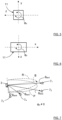
- FIG. 1 shows a top view of a vehicle 1 that comprises a radar system 2 that in turn comprises a vehicle radar transceiver 3 and a control unit 4.
- the radar transceiver 3 has a certain field of view (FOV) 9 and a front side 11 comprising a radar aperture.
- FOV field of view
- the radar transceiver 3 is positioned behind or inside a bumper 8 which serves as a radome for the radar transceiver 3.
- Figure 1 further shows a measuring system 12 for determining the alignment of the vehicle radar transceiver 3, where the alignment is defined by means of a pitch angle ⁇ p , a yaw angle ⁇ y and a roll angle ⁇ r of the radar transceiver 3 with respect to a fixed coordinate system x, y, z as shown in Figure 3-6 .
- Figure 3 shows a schematic perspective view of the radar transceiver 3 in a coordinate system x, y, z
- Figure 4 - Figure 6 show a schematic views of the radar transceiver 3 with its front side 11 in the coordinate system x, y, z, illustrating the pitch angle ⁇ p , the yaw angle ⁇ y and the roll angle ⁇ r of the radar transceiver 3.
- the measuring system 12 comprises the radar system 2 that in turn comprises the radar transceiver 3 and the control unit 4. According to some aspects, the measuring system 12 further comprises at least one target object 7, for example when the target object 7 is comprised in a predetermined test set-up.
- the measuring system 12 is adapted to transmit radar signals 5, to receive reflected radar signals 6 that have been reflected by the target object 7, and to determine a determined azimuth angle ⁇ det and a determined elevation angle ⁇ det to the target object 7 relative a reference plane R by means of the reflected radar signals 6.
- the radar transceiver 3 is adapted to transmit radar signals 5 and receive reflected radar signals 6 that have been reflected by a target object 7.
- the control unit 4 is adapted to control the radar transceiver 3, for example transmission timing, transmission frequency content, as well as the actual transmitted time waveform.
- the control unit 4 is according to some aspects also adapted to perform signal processing in order to extract target data related to the detected target objects, for example 2D FFT for obtaining a Range-Doppler matrix in a previously well-known manner.
- the control unit 4 is connected to an external computer device 20.
- the measuring system 12 comprises target objects 7 that have been determined to be moving.
- the present disclosure is based on the inventor's insight regarding how the pitch angle ⁇ p and the roll angle ⁇ r affect the determined azimuth angle ⁇ det and a determined elevation angle ⁇ det .
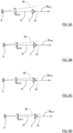
- Figure 8A - Figure 8D illustrates this by showing corresponding azimuth cuts for the different determined azimuth angles ⁇ 1det , ⁇ 2det , ⁇ 3det , ⁇ 4det of the target object 7 1 , 7 2 , 7 3 , 7 4 as illustrated in Figure 7 .
- Figure 8A shows a case where there is a first target object 7 1 at a first determined azimuth angle ⁇ det1 and at a first determined elevation angle ⁇ det1 .
- Figure 8B shows a case where there is a second target object 7 2 at a second determined azimuth angle ⁇ det2 and at a second determined elevation angle ⁇ det2 .
- Figure 8C shows a case where there is a third target object 7 3 at a third determined azimuth angle ⁇ det3 and at a third determined elevation angle ⁇ det3 .
- Figure 8D shows a case where there is a fourth target object 7 4 at a fourth determined azimuth angle ⁇ 4det and at a fourth determined elevation angle ⁇ det4 .
- Different determined values for determined azimuth angle ⁇ det and determined elevation angle ⁇ det can thus be used to determine the pitch alignment error and the roll alignment error by finding these angular values ⁇ p , ⁇ r that satisfy equation (1) above for at least one determined azimuth angles ⁇ det and at least one determined elevation angles ⁇ det .
- a plurality of detections are used.
- the boresight direction B lies in the reference plane R.
- the measuring system 12 is adapted to satisfy the equation by using a non-linear least square fit by means of nonlinear parameter optimization.
- the radar transceiver 3 is mounted behind the bumper 8.
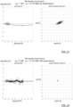
- the dots relate to expectation and the solid line relates to the result of the nonlinear parameter optimization, both as a function of azimuth angle and elevation angle.
- Figure 11 illustrates the estimated parameter values shown as a function of the number of iterations for the parameter optimization described above with reference to Figure 10 .
- the x-axis shows the number of iteration, and the y-axis shows the estimated parameter values.
- the dots relate to expectation and the solid line relates to the result of the nonlinear parameter optimization, both as a function of azimuth angle and elevation angle.
- Figure 13 illustrates the estimated parameter values shown as a function of the number of iterations for the parameter optimization described above with reference to Figure 12 .
- the x-axis shows the number of iteration, and the y-axis shows the estimated parameter values.
- the measuring system 12 is adapted to satisfy the equation by using Bayesian inference.
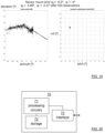
- Figures 14- Figure 19 visualize the mechanics of Bayesian inference where an observation of detected target objects is used to refine knowledge about the parameters that is present in the form of a distribution.
- a prior parameter distribution is updated with each observation to a posterior parameter distribution. As more and more observations of detected target objects get observed the posterior distribution gets sharper over time.
- the x-axis shows an azimuth angle and the y-axis shows an elevation angle for the observations.
- the x-axis shows a radar transceiver pitch misalignment angle
- the y-axis shows a radar transceiver roll misalignment angle.
- the result is very precise at this time, and thus an estimation for the parameters pitch misalignment angle ⁇ p and roll misalignment angle ⁇ r can be determined.
- the result is very precise at this time, and thus an estimation for the parameters pitch misalignment angle ⁇ p and roll misalignment angle ⁇ r can be determined.
- the control unit 4 having determined the pitch misalignment angle ⁇ p and the roll misalignment angle ⁇ r , these can be stored in a memory and used by the control unit 4 that is adapted to performed a compensation for following detections of target objects such that the determined pitch misalignment angle ⁇ p and the roll misalignment angle ⁇ r are compensated for.
- a control unit and a computer program can according to some aspects be used to determine the most likely misalignment values of pitch angle ⁇ p and roll angle ⁇ r .
- FIG 20 schematically illustrates, in terms of a number of functional units, the components of a control unit 70, corresponding to the control unit 4 described, according to an embodiment.
- Processing circuitry 71 is provided using any combination of one or more of a suitable central processing unit (CPU), multiprocessor, microcontroller, digital signal processor (DSP), dedicated hardware accelerator, etc., capable of executing software instructions stored in a computer program product, e.g. in the form of a storage medium 72.
- the processing circuitry 71 may further be provided as at least one application specific integrated circuit (ASIC), or field programmable gate array (FPGA).
- ASIC application specific integrated circuit
- FPGA field programmable gate array
- the processing circuitry 71 is configured to cause the control unit 70 to perform a set of operations, or steps. These operations, or steps, were discussed above in connection to the various measuring systems 12 and methods.
- the storage medium 72 may store the set of operations
- the processing circuitry 71 may be configured to retrieve the set of operations from the storage medium 72 to cause the control unit 70 to perform the set of operations.
- the set of operations may be provided as a set of executable instructions.
- the processing circuitry 71 is thereby arranged to execute methods and operations as herein disclosed.
- the storage medium 72 may also comprise persistent storage, which, for example, can be any single one or combination of magnetic memory, optical memory, solid state memory or even remotely mounted memory.
- the control unit 70 may further comprise a communications interface 73 for communications with at least one other unit.
- the interface 73 may comprise one or more transmitters and receivers, comprising analogue and digital components and a suitable number of ports for wired or wireless communication.
- the processing circuitry 71 is adapted to control the general operation of the control unit 70 e.g. by sending data and control signals to the external unit and the storage medium 72, by receiving data and reports from the external unit, and by retrieving data and instructions from the storage medium 72.
- Other components, as well as the related functionality, of the control unit 70 are omitted in order not to obscure the concepts presented herein.
- Figure 21 shows a computer program product 81 comprising computer executable instructions 82 arranged on a computer readable medium 83 to execute any of the methods disclosed herein.
- the present disclosure also relates to a method for determining the alignment of a vehicle radar transceiver 3, the alignment being defined by means of a pitch angle ⁇ p and a roll angle ⁇ r of the radar transceiver 3 with respect to a fixed coordinate system x, y, z.
- the method comprises transmitting S100 radar signals 5, receiving S200 reflected radar signals 6 that have been reflected by at least one target object 7, and determining S300 a determined azimuth angle ⁇ det and a determined elevation angle ⁇ det to each target object 7 relative a reference plane R using the reflected radar signals 6.
- the method comprises using target objects 7 that have been determined to be moving.
- the method comprises satisfying S510 the equation by using a non-linear least square fit.
- the method comprises satisfying S520 the equation by using Bayesian inference.
- the radar transceivers can be of any suitable kind, and can according to some aspects comprise suitable devices such as antennas, transmitters, receivers, control units etc.
- the control unit 4 may be constituted by one unit or by two or more distributed sub-units.
- the control unit 4 can according to some aspects be adapted to perform one or more of the steps described to be performed by the measuring system 12.
- the present disclosure can be applied to any suitable radar transceiver or radar transceivers comprised in the radar system 2.
- the present disclosure is for example useful in the cases where the radar transceiver 3 is not accessible to the person performing an alignment test, e.g. to put a tilt meter on it. Hence the person performing an alignment test requires a way to know that the radar transceiver 3 is aligned on the vehicle within the tolerance agreed by the radar manufacturer, which is provided by means of the present disclosure.
- alignment of the radar transceiver 3 is directed towards alignment of antennas 21 comprised in the radar transceiver 3, the antennas 21 being adapted to transmit radar signals and receive reflected radar signals in a well-known manner.
- a radar transceiver 3 is an integrated unit, where an adjustment or misalignment of the radar transceiver 3 directly affects the antennas 21 comprised in the radar transceiver 3.
- each target object 7 and the radar transceiver 3 are positioned in a common plane P at a distance h from a ground level G, this is an assumption that is made. This does not necessarily mean that this is the case in practice.
Landscapes
- Engineering & Computer Science (AREA)
- Radar, Positioning & Navigation (AREA)
- Remote Sensing (AREA)
- Physics & Mathematics (AREA)
- Computer Networks & Wireless Communication (AREA)
- General Physics & Mathematics (AREA)
- Electromagnetism (AREA)
- Radar Systems Or Details Thereof (AREA)
Abstract
Description
- The present disclosure relates to determining the alignment of a vehicle radar transceiver, the alignment being defined by means of a pitch angle, a yaw angle and a roll angle, of the radar transceiver with respect to a fixed coordinate system,
- Today, one or more radar transceivers may be mounted on a vehicle in order to detect reflections from surrounding objects in order to implement safety functions such as collision prevention as well as automated/assisted driving. In such a radar transceiver it is required to obtain an azimuth angle in the form of a target bearing angle, a distance with respect to the object, and a relative speed between the vehicle and the object. It is sometimes also necessary to report the elevation angle to the target.
- For most vehicle radar applications it is important to measure the azimuth angle with a relatively high degree of precision. The angle accuracy of a radar system depends on fundamental parameters like number of receive channels, component tolerances, assembly precision and installation conditions.
- A proper radar transceiver orientation when mounted in a vehicle is given when its x- and y- axis span a plane that is parallel to the vehicle's x-y-plane and its x-axis points along a specified mounting boresight direction. The full 3D misalignment is the triple of angles for which the radar sensor, or radar trasnsceiver, has to be rotated to get it from its proper orientation to the actual misaligned orientation. The first rotation is around its z-axis and is called yaw. The second rotation is around its Y axis and is called pitch and the third rotation is around its x-axis, it is called roll.
- To transform a target coordinate from a radar transceivers coordinate system to a vehicle coordinate system it is crucial to know the full position and orientation of the radar transceivers coordinate system in the vehicle coordinate system. Due to mounting tolerances or due to impact of an accident it is possible that the radar sensor is misaligned in the pitch angle and/or the roll angle also. In this case a correct transform of radar targets to other coordinate systems (e.g. car coordinate system) is not possible, if the pitch and roll misalignment is not known. Additionally it is not possible to estimate yaw misalignment correctly, if pitch and roll misalignment are not known.
- Radar transceivers can furthermore be affected by various vehicle components such as different types of bumpers and vehicle front and rear section geometries. Radar transceivers are also affected by variations during manufacturing and assembly. Sensor systems therefore require calibration to produce accurate sensor output signals. This calibration is often performed during manufacture in a factory, which is time-consuming and drives cost. Optimal calibration parameters may also change over time, which necessitates a re-calibration, which may be inconvenient.
- It is an object of the present disclosure to present an alternative and less complicated method and system for detecting alignment and possible misalignment of a radar transceiver.
- Said object is achieved by means of a measuring system for determining the alignment of a vehicle radar transceiver, the alignment being defined by means of a pitch angle ϕp and a roll angle ϕr of the radar transceiver with respect to a fixed coordinate system. The measuring system comprises a radar system that in turn comprises the radar transceiver and a control unit. The measuring system is adapted to transmit radar signals, receive reflected radar signals that have been reflected by at least one target object, and to determine a determined azimuth angle θdet and a determined elevation angle ψdet to each target target object relative a reference plane R by means of the reflected radar signals. The measuring system is further adapted to assume that each target object and the radar transceiver are positioned in a common plane P at a distance d from a ground level G, and to estimate the pitch angle αp and the roll angle αr of the radar transceiver with respect to a fixed coordinate system using the determined angles θdet, ψdet such that the equation

- This means that an accurate estimation of pitch angle αp the roll angle αr of the radar transceiver with respect to a fixed coordinate system can be obtained in a relatively uncomplicated manner. This estimation is based on the assumption that each target object and the radar transceiver are positioned in a common plane, and is based on the inventor's insight regarding how the pitch angle αp and the roll angle αr affect the determined azimuth angle θdet and a determined elevation angle ψdet.
- According to some aspects, the measuring system is adapted to satisfy the equation by using a non-linear least square fit.
- According to some aspects, the measuring system is adapted to satisfy the equation using Bayesian inference.
- This means that well-known methods can be used to provide the desired estimation. Many other numerical methods are of course applicable.
- This object is also achieved by means of methods and vehicles that are associated with the above advantages.
- The present disclosure will now be described more in detail with reference to the appended drawings, where:
- Figure 1
- shows a schematic top view of a vehicle and a measuring system;
- Figure 2
- shows a schematic side view of a radar transceiver and a target object;
- Figure 3
- shows a schematic perspective view of the radar transceiver in a coordinate system;
- Figure 4
- shows a schematic first view of the radar transceiver in the coordinate system;
- Figure 5
- shows a schematic second view of the radar transceiver in the coordinate system;
- Figure 6
- shows a schematic third view of the radar transceiver in the coordinate system;
- Figure 7
- shows a schematic side perspective view of a radar transceiver target objects;
- Figure 8A - 8D
- illustrate azimuth cuts for different determined azimuth angles;
- Figure 9
- shows a graphical representation of how determined azimuth angle and determined elevation angle relate to each other for a certain misalignment;
- Figure 10
- illustrates nonlinear parameter optimization for a cross traffic scenario with no mounting error;
- Figure 11
- illustrates nonlinear parameter optimization for a cross traffic scenario with no mounting error;
- Figure 12
- illustrates nonlinear parameter optimization for a cross traffic scenario with a mounting error;
- Figure 13
- illustrates nonlinear parameter optimization for a cross traffic scenario with a mounting error;
- Figure 14-16
- illustrate Bayesian inference for a cross traffic scenario with no mounting error;
- Figure 17-19
- illustrate Bayesian inference for a cross traffic scenario with a mounting error;
- Figure 20
- schematically illustrates a control unit;
- Figure 21
- shows an example computer program product; and
- Figure 22
- shows a flowchart for methods according to the present disclosure.
- Aspects of the present disclosure will now be described more fully with reference to the accompanying drawings. The different devices and methods disclosed herein can, however, be realized in many different forms and should not be construed as being limited to the aspects set forth herein. Like numbers in the drawings refer to like elements throughout.
- The terminology used herein is for describing aspects of the disclosure only and is not intended to limit the disclosure. As used herein, the singular forms "a", "an" and "the" are intended to include the plural forms as well, unless the context clearly indicates otherwise.
-
Figure 1 shows a top view of avehicle 1 that comprises aradar system 2 that in turn comprises avehicle radar transceiver 3 and acontrol unit 4. Theradar transceiver 3 has a certain field of view (FOV) 9 and afront side 11 comprising a radar aperture. - According to some aspects, the
radar transceiver 3 is positioned behind or inside abumper 8 which serves as a radome for theradar transceiver 3. -
Figure 1 further shows a measuringsystem 12 for determining the alignment of thevehicle radar transceiver 3, where the alignment is defined by means of a pitch angle ϕp, a yaw angle ϕy and a roll angle ϕr of theradar transceiver 3 with respect to a fixed coordinate system x, y, z as shown inFigure 3-6 .Figure 3 shows a schematic perspective view of theradar transceiver 3 in a coordinate system x, y, z, andFigure 4 - Figure 6 show a schematic views of theradar transceiver 3 with itsfront side 11 in the coordinate system x, y, z, illustrating the pitch angle ϕp, the yaw angle ϕy and the roll angle ϕr of theradar transceiver 3. - The measuring
system 12 comprises theradar system 2 that in turn comprises theradar transceiver 3 and thecontrol unit 4. According to some aspects, the measuringsystem 12 further comprises at least onetarget object 7, for example when thetarget object 7 is comprised in a predetermined test set-up. - With reference also to
Figure 2 , the measuringsystem 12 is adapted to transmitradar signals 5, to receive reflectedradar signals 6 that have been reflected by thetarget object 7, and to determine a determined azimuth angle θdet and a determined elevation angle ψdet to thetarget object 7 relative a reference plane R by means of the reflected radar signals 6. - For this purpose, the
radar transceiver 3 is adapted to transmitradar signals 5 and receive reflectedradar signals 6 that have been reflected by atarget object 7. Thecontrol unit 4 is adapted to control theradar transceiver 3, for example transmission timing, transmission frequency content, as well as the actual transmitted time waveform. Thecontrol unit 4 is according to some aspects also adapted to perform signal processing in order to extract target data related to the detected target objects, for example 2D FFT for obtaining a Range-Doppler matrix in a previously well-known manner. According to some aspects, thecontrol unit 4 is connected to anexternal computer device 20. - According to the present disclosure, the measuring
system 12 is further adapted to assume that thetarget object 7 and theradar transceiver 3 are positioned in a common plane P at a distance d from a ground level G, and to estimate the pitch angle αp and the roll angle αr of theradar transceiver 3 with respect to a fixed coordinate system x, y, z using on the determined angles θdet, ψdet such that the equation
- This means that an accurate estimation of pitch angle αp the roll angle αr of the
radar transceiver 3 with respect to a fixed coordinate system x, y, z can be obtained in a relatively uncomplicated manner. - According to some aspects, the measuring
system 12 comprises target objects 7 that have been determined to be moving. - The present disclosure is based on the inventor's insight regarding how the pitch angle αp and the roll angle αr affect the determined azimuth angle θdet and a determined elevation angle ψdet.
- This is illustrated in
Figure 7 where there is a certain error due to pitch misalignment such that ϕp ≠ 0. This means that, depending on the determined azimuth angle θdet1, θdet2, θdet3, θdet4 of thetarget object radar transceiver 3 are assumed to lie in the common plane P. -
Figure 8A - Figure 8D illustrates this by showing corresponding azimuth cuts for the different determined azimuth angles θ1det, θ2det, θ3det, θ4det of thetarget object Figure 7 . -
Figure 8A shows a case where there is afirst target object 71 at a first determined azimuth angle θdet1 and at a first determined elevation angle ψdet1. -
Figure 8B shows a case where there is asecond target object 72 at a second determined azimuth angle θdet2 and at a second determined elevation angle ψdet2. -
Figure 8C shows a case where there is athird target object 73 at a third determined azimuth angle θdet3 and at a third determined elevation angle ψdet3. -
Figure 8D shows a case where there is afourth target object 74 at a fourth determined azimuth angle θ4det and at a fourth determined elevation angle ψdet4. - The larger the determined azimuth angle becomes relative a boresight direction B, the smaller the determined elevation angle becomes due to the pitch misalignment that separates the common plane P from the reference plane R.
-
Figure 9 provides a graphical representation of how the determined azimuth angle and the determined elevation angle relates to each other for a pitch misalignment of ϕp = -6,5° and a roll misalignment of ϕr = -4,0°. For example, a target object 7' that is detected at determined azimuth angle θdet = 0,0° will approximately result in a determined elevation angle ψdet ≈ 6,5°, and a target object 7'' that is detected at determined elevation angle ψdet = 0,0 ° will approximately result in a determined azimuth angle θdet ≈ 59 °. - Different determined values for determined azimuth angle θdet and determined elevation angle ψdet can thus be used to determine the pitch alignment error and the roll alignment error by finding these angular values ϕp, ϕr that satisfy equation (1) above for at least one determined azimuth angles θdet and at least one determined elevation angles ψdet. Typically, a plurality of detections are used.
- According to some aspects, the boresight direction B lies in the reference plane R.
- Different numerical methods can be used to solve for the pitch misalignment angle ϕp and the roll misalignment angle ϕr. Examples of cases using different numerical methods will be disclosed in the following.
- According to some aspects, with reference to
Figure 10-13 , the measuringsystem 12 is adapted to satisfy the equation by using a non-linear least square fit by means of nonlinear parameter optimization. In the examples described, there is a cross traffic scenario with five crossing cars, and theradar transceiver 3 is mounted behind thebumper 8. -
Figure 10 illustrates a nonlinear parameter optimization without any mounting error, i.e., with a pitch misalignment of ϕp = 0° and a roll misalignment of ϕr = 0° where the resulting calculated pitch misalignment is ϕp = 0,42° and the resulting calculated roll misalignment is ϕr = -0,11°. The dots relate to expectation and the solid line relates to the result of the nonlinear parameter optimization, both as a function of azimuth angle and elevation angle. -
Figure 11 illustrates the estimated parameter values shown as a function of the number of iterations for the parameter optimization described above with reference toFigure 10 . The x-axis shows the number of iteration, and the y-axis shows the estimated parameter values. -
Figure 12 illustrates a nonlinear parameter optimization with a with a pitch misalignment of ϕp = -6.5° and a roll misalignment of ϕr = -4.0°, where the resulting calculated pitch misalignment is ϕp = -5,84° and the resulting calculated roll misalignment is ϕr = -3,68°. The dots relate to expectation and the solid line relates to the result of the nonlinear parameter optimization, both as a function of azimuth angle and elevation angle. -
Figure 13 illustrates the estimated parameter values shown as a function of the number of iterations for the parameter optimization described above with reference toFigure 12 . The x-axis shows the number of iteration, and the y-axis shows the estimated parameter values. - According to some aspects, with reference to
Figure 14-19 , the measuringsystem 12 is adapted to satisfy the equation by using Bayesian inference. In the examples described, there is a cross traffic scenario with five crossing cars, and theradar transceiver 3 is mounted behind thebumper 8. -
Figures 14- Figure 19 visualize the mechanics of Bayesian inference where an observation of detected target objects is used to refine knowledge about the parameters that is present in the form of a distribution. A prior parameter distribution is updated with each observation to a posterior parameter distribution. As more and more observations of detected target objects get observed the posterior distribution gets sharper over time. In each left-hand diagram, the x-axis shows an azimuth angle and the y-axis shows an elevation angle for the observations. In each right-hand diagram the x-axis shows a radar transceiver pitch misalignment angle, and the y-axis shows a radar transceiver roll misalignment angle. - In
Figure 14 - Figure 16 there is no mounting error, i.e., there is a pitch misalignment of ϕp = 0° and a roll misalignment of ϕr = 0°. - In
Figure 14 , after 0 observations, no observation of detected target objects has been captured, so the distribution of pitch and roll is the initial distribution. The resulting calculated pitch misalignment is ϕp = 0° and the resulting calculated roll misalignment is ϕr = 0°. -
Figure 15 shows the posterior distribution after 50 observations; the resulting calculated pitch misalignment is ϕp = 1,93° and the resulting calculated roll misalignment is ϕr = -0,79°. -
Figure 16 shows the posterior distribution after 500 observations; the resulting calculated pitch misalignment is ϕp = 0,38° and the resulting calculated roll misalignment is ϕr = -0,15°. The result is very precise at this time, and thus an estimation for the parameters pitch misalignment angle ϕp and roll misalignment angle ϕr can be determined. - In
Figure 17 - Figure 19 there is a mounting error; there is a pitch misalignment of ϕp = -6,5° and a roll misalignment of ϕr = -4°. - In
Figure 17 , after 0 observations, no observation of detected target objects has been captured, so the distribution of pitch and roll is the initial distribution. The resulting calculated pitch misalignment is ϕp = 0° and the resulting calculated roll misalignment is ϕr = 0°. -
Figure 18 shows the posterior distribution after 50 observations; the resulting calculated pitch misalignment is ϕp = -6,15° and the resulting calculated roll misalignment is ϕr = -3,13°. -
Figure 19 shows the posterior distribution after 500 observations; the resulting calculated pitch misalignment is ϕp = -5,89° and the resulting calculated roll misalignment is ϕr = -3,57°. The result is very precise at this time, and thus an estimation for the parameters pitch misalignment angle ϕp and roll misalignment angle ϕr can be determined. - Only one implementation example has been provided for each one of the numerical methods described above, there are of course many other ways to implement these methods.
- Furthermore, the numerical methods described above only present examples of how to derive the pitch misalignment angle ϕp and the roll misalignment angle ϕr, many other such numerical methods are of course conceivable and apparent for the skilled person.
- According to some aspects, having determined the pitch misalignment angle ϕp and the roll misalignment angle ϕr, these can be stored in a memory and used by the
control unit 4 that is adapted to performed a compensation for following detections of target objects such that the determined pitch misalignment angle ϕp and the roll misalignment angle ϕr are compensated for. - As described more in detail below, a control unit and a computer program can according to some aspects be used to determine the most likely misalignment values of pitch angle ϕp and roll angle ϕr.
-
Figure 20 schematically illustrates, in terms of a number of functional units, the components of acontrol unit 70, corresponding to thecontrol unit 4 described, according to an embodiment.Processing circuitry 71 is provided using any combination of one or more of a suitable central processing unit (CPU), multiprocessor, microcontroller, digital signal processor (DSP), dedicated hardware accelerator, etc., capable of executing software instructions stored in a computer program product, e.g. in the form of astorage medium 72. Theprocessing circuitry 71 may further be provided as at least one application specific integrated circuit (ASIC), or field programmable gate array (FPGA). - Particularly, the
processing circuitry 71 is configured to cause thecontrol unit 70 to perform a set of operations, or steps. These operations, or steps, were discussed above in connection to the various measuringsystems 12 and methods. For example, thestorage medium 72 may store the set of operations, and theprocessing circuitry 71 may be configured to retrieve the set of operations from thestorage medium 72 to cause thecontrol unit 70 to perform the set of operations. The set of operations may be provided as a set of executable instructions. Thus, theprocessing circuitry 71 is thereby arranged to execute methods and operations as herein disclosed. - The
storage medium 72 may also comprise persistent storage, which, for example, can be any single one or combination of magnetic memory, optical memory, solid state memory or even remotely mounted memory. - The
control unit 70 may further comprise acommunications interface 73 for communications with at least one other unit. As such, theinterface 73 may comprise one or more transmitters and receivers, comprising analogue and digital components and a suitable number of ports for wired or wireless communication. - The
processing circuitry 71 is adapted to control the general operation of thecontrol unit 70 e.g. by sending data and control signals to the external unit and thestorage medium 72, by receiving data and reports from the external unit, and by retrieving data and instructions from thestorage medium 72. Other components, as well as the related functionality, of thecontrol unit 70 are omitted in order not to obscure the concepts presented herein. -
Figure 21 shows acomputer program product 81 comprising computerexecutable instructions 82 arranged on a computer readable medium 83 to execute any of the methods disclosed herein. - With reference to
Figure 22 , the present disclosure also relates to a method for determining the alignment of avehicle radar transceiver 3, the alignment being defined by means of a pitch angle ϕp and a roll angle ϕr of theradar transceiver 3 with respect to a fixed coordinate system x, y, z. The method comprises transmitting S100 radar signals 5, receiving S200 reflectedradar signals 6 that have been reflected by at least onetarget object 7, and determining S300 a determined azimuth angle θdet and a determined elevation angle ψdet to eachtarget object 7 relative a reference plane R using the reflected radar signals 6. - The method further comprises assuming S400 that each
target object 7 and theradar transceiver 3 are positioned in a common plane P at a distance h from a ground level G; and estimating S500 the pitch angle αp and the roll angle αr of theradar transceiver 3 with respect to a fixed coordinate system x, y, z using the determined angles θdet, ψdet such that the equation
- According to some aspects, the method comprises using
target objects 7 that have been determined to be moving. - According to some aspects, the method comprises satisfying S510 the equation by using a non-linear least square fit.
- According to some aspects, the method comprises satisfying S520 the equation by using Bayesian inference.
- The present disclosure is not limited to the examples discussed, but may vary freely within the scope of the appended claims. For example, the radar transceivers can be of any suitable kind, and can according to some aspects comprise suitable devices such as antennas, transmitters, receivers, control units etc.
- The
control unit 4 may be constituted by one unit or by two or more distributed sub-units. Thecontrol unit 4 can according to some aspects be adapted to perform one or more of the steps described to be performed by the measuringsystem 12. - The present disclosure can be applied to any suitable radar transceiver or radar transceivers comprised in the
radar system 2. - The present disclosure is for example useful in the cases where the
radar transceiver 3 is not accessible to the person performing an alignment test, e.g. to put a tilt meter on it. Hence the person performing an alignment test requires a way to know that theradar transceiver 3 is aligned on the vehicle within the tolerance agreed by the radar manufacturer, which is provided by means of the present disclosure. - According to some aspects, alignment of the
radar transceiver 3 is directed towards alignment ofantennas 21 comprised in theradar transceiver 3, theantennas 21 being adapted to transmit radar signals and receive reflected radar signals in a well-known manner. According to some aspects, aradar transceiver 3 is an integrated unit, where an adjustment or misalignment of theradar transceiver 3 directly affects theantennas 21 comprised in theradar transceiver 3. - It should be noted that when it mentioned that each
target object 7 and theradar transceiver 3 are positioned in a common plane P at a distance h from a ground level G, this is an assumption that is made. This does not necessarily mean that this is the case in practice.
Claims (9)
- A method for determining the alignment of a vehicle radar transceiver (3), the alignment being defined by means of a pitch angle (ϕp) and a roll angle (ϕr) of the radar transceiver (3) with respect to a fixed coordinate system (x, y, z), where the method comprises:transmitting (S100) radar signals (5);receiving (S200) reflected radar signals (6) that have been reflected by at least one target object (7); anddetermining (S300) a determined azimuth angle (θdet) and a determined elevation angle (ψdet) to each target object (7) relative a reference plane (R) using the reflected radar signals (6) ;
wherein the method further comprises:assuming (S400) that each target object (7) and the radar transceiver (3) are positioned in a common plane (P) at a distance (h) from a ground level (G); andestimating (S500) the pitch angle (αp) and the roll angle (αr) of the radar transceiver (3) with respect to a fixed coordinate system (x, y, z) using the determined angles (θdet, ψdet) such that the equation
- The method according to claim 1, wherein the method comprises using target objects (7) that have been determined to be moving.
- The method according to any one of the claims 1 or 2, wherein the method comprises satisfying (S510) the equation by using a non-linear least square fit.
- The method according to any one of the claims 1 or 2, wherein the method comprises satisfying (S520) the equation by using Bayesian inference.
- A measuring system (12) for determining the alignment of a vehicle radar transceiver (3), the alignment being defined by means of a pitch angle (ϕp) and a roll angle (ϕr) of the radar transceiver (3) with respect to a fixed coordinate system (x, y, z), where the measuring system (12) comprises a radar system (2) that in turn comprises the radar transceiver (3) and a control unit (4), where the measuring system (12) is adapted to:- transmit radar signals (5),- receive reflected radar signals (6) that have been reflected by at least one target object (7), and to- determine a determined azimuth angle (θdet) and a determined elevation angle (ψdet) to each target target object (7) relative a reference plane (R) by means of the reflected radar signals (6);
characterized in that the measuring system (12) further is adapted to:- assume that each target object (7) and the radar transceiver (3) are positioned in a common plane (P) at a distance (d) from a ground level (G); and to- estimate the pitch angle (αp) and the roll angle (αr) of the radar transceiver (3) with respect to a fixed coordinate system (x, y, z) using the determined angles (θdet, ψdet) such that the equation
- The measuring system according to claim 5, wherein the measuring system (12) comprises target objects (7) that have been determined to be moving.
- The measuring system according to any one of the claims 5 or 6, wherein the measuring system (12) is adapted to satisfy the equation by using a non-linear least square fit.
- The measuring system according to any one of the claims 5 or 6, wherein the measuring system (12) is adapted to satisfy the equation using Bayesian inference.
- A vehicle (1) comprising the measuring system (12) according to any one of the claims 5-8.
Priority Applications (5)
| Application Number | Priority Date | Filing Date | Title |
|---|---|---|---|
| EP22163817.4A EP4249941A1 (en) | 2022-03-23 | 2022-03-23 | Alignment detection for a vehicle radar transceiver |
| US18/846,035 US20250189630A1 (en) | 2022-03-23 | 2023-03-17 | Alignment detection for a vehicle radar transceiver |
| JP2024554993A JP7742950B2 (en) | 2022-03-23 | 2023-03-17 | Alignment detection for vehicle radar transceivers |
| CN202380025938.6A CN118829899A (en) | 2022-03-23 | 2023-03-17 | Alignment detection for vehicle radar transceivers |
| PCT/EP2023/056866 WO2023180196A1 (en) | 2022-03-23 | 2023-03-17 | Alignment detection for a vehicle radar transceiver |
Applications Claiming Priority (1)
| Application Number | Priority Date | Filing Date | Title |
|---|---|---|---|
| EP22163817.4A EP4249941A1 (en) | 2022-03-23 | 2022-03-23 | Alignment detection for a vehicle radar transceiver |
Publications (1)
| Publication Number | Publication Date |
|---|---|
| EP4249941A1 true EP4249941A1 (en) | 2023-09-27 |
Family
ID=80930110
Family Applications (1)
| Application Number | Title | Priority Date | Filing Date |
|---|---|---|---|
| EP22163817.4A Pending EP4249941A1 (en) | 2022-03-23 | 2022-03-23 | Alignment detection for a vehicle radar transceiver |
Country Status (5)
| Country | Link |
|---|---|
| US (1) | US20250189630A1 (en) |
| EP (1) | EP4249941A1 (en) |
| JP (1) | JP7742950B2 (en) |
| CN (1) | CN118829899A (en) |
| WO (1) | WO2023180196A1 (en) |
Cited By (1)
| Publication number | Priority date | Publication date | Assignee | Title |
|---|---|---|---|---|
| US20250035436A1 (en) * | 2023-07-27 | 2025-01-30 | Aptiv Technologies Limited | NLS Using a Bounded Linear Initial Search Space and a Fixed Grid with Pre-Calculated Variables |
Families Citing this family (1)
| Publication number | Priority date | Publication date | Assignee | Title |
|---|---|---|---|---|
| KR20240145205A (en) * | 2023-03-27 | 2024-10-07 | 주식회사 에이치엘클레무브 | Angle Compensation Device and Method, and Radar Device including the same |
Citations (2)
| Publication number | Priority date | Publication date | Assignee | Title |
|---|---|---|---|---|
| DE102015012246A1 (en) * | 2015-09-18 | 2016-03-03 | Daimler Ag | Method for determining a mounting orientation of a radar sensor |
| WO2021070916A1 (en) * | 2019-10-09 | 2021-04-15 | 株式会社デンソー | Axial deviation estimating device |
Family Cites Families (3)
| Publication number | Priority date | Publication date | Assignee | Title |
|---|---|---|---|---|
| US20100076710A1 (en) * | 2008-09-19 | 2010-03-25 | Caterpillar Inc. | Machine sensor calibration system |
| DE102015118874A1 (en) * | 2015-11-04 | 2017-05-04 | Valeo Schalter Und Sensoren Gmbh | Method for operating a sensor system of a motor vehicle, driver assistance system and system for calibrating a sensor system of a motor vehicle |
| JP7252110B2 (en) * | 2019-10-09 | 2023-04-04 | 株式会社Soken | Axial misalignment estimator |
-
2022
- 2022-03-23 EP EP22163817.4A patent/EP4249941A1/en active Pending
-
2023
- 2023-03-17 JP JP2024554993A patent/JP7742950B2/en active Active
- 2023-03-17 CN CN202380025938.6A patent/CN118829899A/en active Pending
- 2023-03-17 WO PCT/EP2023/056866 patent/WO2023180196A1/en not_active Ceased
- 2023-03-17 US US18/846,035 patent/US20250189630A1/en active Pending
Patent Citations (3)
| Publication number | Priority date | Publication date | Assignee | Title |
|---|---|---|---|---|
| DE102015012246A1 (en) * | 2015-09-18 | 2016-03-03 | Daimler Ag | Method for determining a mounting orientation of a radar sensor |
| WO2021070916A1 (en) * | 2019-10-09 | 2021-04-15 | 株式会社デンソー | Axial deviation estimating device |
| US20220229168A1 (en) * | 2019-10-09 | 2022-07-21 | Denso Corporation | Axial deviation estimating device |
Cited By (2)
| Publication number | Priority date | Publication date | Assignee | Title |
|---|---|---|---|---|
| US20250035436A1 (en) * | 2023-07-27 | 2025-01-30 | Aptiv Technologies Limited | NLS Using a Bounded Linear Initial Search Space and a Fixed Grid with Pre-Calculated Variables |
| US12546589B2 (en) * | 2023-07-27 | 2026-02-10 | Aptiv Technologies AG | NLS using a bounded linear initial search space and a fixed grid with pre-calculated variables |
Also Published As
| Publication number | Publication date |
|---|---|
| JP2025509675A (en) | 2025-04-11 |
| US20250189630A1 (en) | 2025-06-12 |
| WO2023180196A1 (en) | 2023-09-28 |
| CN118829899A (en) | 2024-10-22 |
| JP7742950B2 (en) | 2025-09-22 |
Similar Documents
| Publication | Publication Date | Title |
|---|---|---|
| US12146982B2 (en) | Method for calibrating a MIMO radar sensor for motor vehicles | |
| US10809355B2 (en) | Apparatus and method for detecting alignment of sensor and calibrating antenna pattern response in an automotive detection system | |
| KR102179784B1 (en) | Method for calibrating sensors in automobiles for angle measurement, calculation devices, driver assistance systems, and automobiles | |
| JP7081046B2 (en) | How to detect angle measurement error in radar sensor | |
| US10422857B2 (en) | Device for ascertaining a misalignment of a detection unit fastened on a vehicle | |
| US20170261599A1 (en) | Method of automatic sensor pose estimation | |
| CN109425852B (en) | Calibration method and device for automobile and vehicle radar | |
| US20250189630A1 (en) | Alignment detection for a vehicle radar transceiver | |
| US10191148B2 (en) | Radar system for vehicle and method for measuring azimuth therein | |
| CN113030887B (en) | Installation angle offline calibration method and device based on millimeter wave radar | |
| JP2009281862A (en) | Axis adjusting method of radar device and axis adjusting device | |
| CN110940973B (en) | Angle measurement method and device for radar target detection | |
| US11378678B2 (en) | Method as well as system for determining the three-dimensional alignment of components of a radar system | |
| US12032060B2 (en) | Ambiguity mitigation based on common field of view of radar systems | |
| CN111289949B (en) | A blind spot monitoring radar test method and device | |
| US11313961B2 (en) | Method and device for identifying the height of an object | |
| CN112213700B (en) | Millimeter wave angle radar calibration method and millimeter wave angle radar system | |
| EP4249942A1 (en) | Alignment detection for a vehicle radar transceiver | |
| KR102825481B1 (en) | Radar alignment apparatus for vehicle and method thereof | |
| US12625232B2 (en) | Calibration process for vehicular radar sensing system | |
| EP4246175B1 (en) | Iterative calibration of dynamic and static vehicle data in a vehicle radar system | |
| EP4253994A1 (en) | Sensor calibration based on strings of detections | |
| CN215768988U (en) | Calibration auxiliary device and vehicle-mounted radar calibration system | |
| US20240111021A1 (en) | System and method for radar calibration | |
| CN116736246A (en) | Calibration methods, devices, electronic equipment and storage media for vehicle-mounted millimeter wave radar |
Legal Events
| Date | Code | Title | Description |
|---|---|---|---|
| PUAI | Public reference made under article 153(3) epc to a published international application that has entered the european phase |
Free format text: ORIGINAL CODE: 0009012 |
|
| STAA | Information on the status of an ep patent application or granted ep patent |
Free format text: STATUS: THE APPLICATION HAS BEEN PUBLISHED |
|
| AK | Designated contracting states |
Kind code of ref document: A1 Designated state(s): AL AT BE BG CH CY CZ DE DK EE ES FI FR GB GR HR HU IE IS IT LI LT LU LV MC MK MT NL NO PL PT RO RS SE SI SK SM TR |
|
| STAA | Information on the status of an ep patent application or granted ep patent |
Free format text: STATUS: REQUEST FOR EXAMINATION WAS MADE |
|
| RAP3 | Party data changed (applicant data changed or rights of an application transferred) |
Owner name: MAGNA ELECTRONICS SWEDEN AB |
|
| 17P | Request for examination filed |
Effective date: 20240325 |
|
| RBV | Designated contracting states (corrected) |
Designated state(s): AL AT BE BG CH CY CZ DE DK EE ES FI FR GB GR HR HU IE IS IT LI LT LU LV MC MK MT NL NO PL PT RO RS SE SI SK SM TR |
|
| RAP3 | Party data changed (applicant data changed or rights of an application transferred) |
Owner name: MAGNA ELECTRONICS SWEDEN AB |
|
| STAA | Information on the status of an ep patent application or granted ep patent |
Free format text: STATUS: EXAMINATION IS IN PROGRESS |
|
| 17Q | First examination report despatched |
Effective date: 20250515 |