EP4249845A2 - Systèmes et procédés d'inspection avec gaines de profil aérodynamique - Google Patents
Systèmes et procédés d'inspection avec gaines de profil aérodynamique Download PDFInfo
- Publication number
- EP4249845A2 EP4249845A2 EP23158302.2A EP23158302A EP4249845A2 EP 4249845 A2 EP4249845 A2 EP 4249845A2 EP 23158302 A EP23158302 A EP 23158302A EP 4249845 A2 EP4249845 A2 EP 4249845A2
- Authority
- EP
- European Patent Office
- Prior art keywords
- airfoil
- locators
- sheath
- various embodiments
- ibr
- Prior art date
- Legal status (The legal status is an assumption and is not a legal conclusion. Google has not performed a legal analysis and makes no representation as to the accuracy of the status listed.)
- Pending
Links
- 238000000034 method Methods 0.000 title claims abstract description 80
- 238000007689 inspection Methods 0.000 title description 48
- 238000010168 coupling process Methods 0.000 claims abstract description 24
- 238000005859 coupling reaction Methods 0.000 claims abstract description 24
- 230000008878 coupling Effects 0.000 claims abstract description 23
- 230000004044 response Effects 0.000 claims description 21
- 238000004519 manufacturing process Methods 0.000 claims description 9
- 238000013461 design Methods 0.000 claims description 4
- 238000003860 storage Methods 0.000 claims description 3
- 230000008569 process Effects 0.000 description 26
- 230000008439 repair process Effects 0.000 description 22
- 230000008901 benefit Effects 0.000 description 6
- 230000003287 optical effect Effects 0.000 description 4
- 230000000694 effects Effects 0.000 description 3
- 230000005355 Hall effect Effects 0.000 description 2
- 230000006870 function Effects 0.000 description 2
- 238000012986 modification Methods 0.000 description 2
- 230000004048 modification Effects 0.000 description 2
- 230000001902 propagating effect Effects 0.000 description 2
- 230000003068 static effect Effects 0.000 description 2
- 238000012935 Averaging Methods 0.000 description 1
- 230000001154 acute effect Effects 0.000 description 1
- 239000000853 adhesive Substances 0.000 description 1
- 230000001070 adhesive effect Effects 0.000 description 1
- 238000005266 casting Methods 0.000 description 1
- 238000004891 communication Methods 0.000 description 1
- 230000006835 compression Effects 0.000 description 1
- 238000007906 compression Methods 0.000 description 1
- 238000010586 diagram Methods 0.000 description 1
- 238000006073 displacement reaction Methods 0.000 description 1
- 239000000446 fuel Substances 0.000 description 1
- 230000001939 inductive effect Effects 0.000 description 1
- 238000003754 machining Methods 0.000 description 1
- 239000000463 material Substances 0.000 description 1
- 238000005259 measurement Methods 0.000 description 1
- 239000002674 ointment Substances 0.000 description 1
- 238000010248 power generation Methods 0.000 description 1
- 238000002360 preparation method Methods 0.000 description 1
- 238000004513 sizing Methods 0.000 description 1
- 239000007787 solid Substances 0.000 description 1
- 238000003466 welding Methods 0.000 description 1
Images


Classifications
-
- F—MECHANICAL ENGINEERING; LIGHTING; HEATING; WEAPONS; BLASTING
- F01—MACHINES OR ENGINES IN GENERAL; ENGINE PLANTS IN GENERAL; STEAM ENGINES
- F01D—NON-POSITIVE DISPLACEMENT MACHINES OR ENGINES, e.g. STEAM TURBINES
- F01D21/00—Shutting-down of machines or engines, e.g. in emergency; Regulating, controlling, or safety means not otherwise provided for
- F01D21/003—Arrangements for testing or measuring
-
- G—PHYSICS
- G06—COMPUTING; CALCULATING OR COUNTING
- G06F—ELECTRIC DIGITAL DATA PROCESSING
- G06F30/00—Computer-aided design [CAD]
- G06F30/20—Design optimisation, verification or simulation
- G06F30/25—Design optimisation, verification or simulation using particle-based methods
-
- B—PERFORMING OPERATIONS; TRANSPORTING
- B23—MACHINE TOOLS; METAL-WORKING NOT OTHERWISE PROVIDED FOR
- B23P—METAL-WORKING NOT OTHERWISE PROVIDED FOR; COMBINED OPERATIONS; UNIVERSAL MACHINE TOOLS
- B23P15/00—Making specific metal objects by operations not covered by a single other subclass or a group in this subclass
- B23P15/02—Making specific metal objects by operations not covered by a single other subclass or a group in this subclass turbine or like blades from one piece
-
- B—PERFORMING OPERATIONS; TRANSPORTING
- B25—HAND TOOLS; PORTABLE POWER-DRIVEN TOOLS; MANIPULATORS
- B25J—MANIPULATORS; CHAMBERS PROVIDED WITH MANIPULATION DEVICES
- B25J9/00—Programme-controlled manipulators
- B25J9/16—Programme controls
- B25J9/1679—Programme controls characterised by the tasks executed
- B25J9/1684—Tracking a line or surface by means of sensors
-
- F—MECHANICAL ENGINEERING; LIGHTING; HEATING; WEAPONS; BLASTING
- F01—MACHINES OR ENGINES IN GENERAL; ENGINE PLANTS IN GENERAL; STEAM ENGINES
- F01D—NON-POSITIVE DISPLACEMENT MACHINES OR ENGINES, e.g. STEAM TURBINES
- F01D5/00—Blades; Blade-carrying members; Heating, heat-insulating, cooling or antivibration means on the blades or the members
- F01D5/005—Repairing methods or devices
-
- F—MECHANICAL ENGINEERING; LIGHTING; HEATING; WEAPONS; BLASTING
- F01—MACHINES OR ENGINES IN GENERAL; ENGINE PLANTS IN GENERAL; STEAM ENGINES
- F01D—NON-POSITIVE DISPLACEMENT MACHINES OR ENGINES, e.g. STEAM TURBINES
- F01D5/00—Blades; Blade-carrying members; Heating, heat-insulating, cooling or antivibration means on the blades or the members
- F01D5/30—Fixing blades to rotors; Blade roots ; Blade spacers
-
- F—MECHANICAL ENGINEERING; LIGHTING; HEATING; WEAPONS; BLASTING
- F01—MACHINES OR ENGINES IN GENERAL; ENGINE PLANTS IN GENERAL; STEAM ENGINES
- F01D—NON-POSITIVE DISPLACEMENT MACHINES OR ENGINES, e.g. STEAM TURBINES
- F01D5/00—Blades; Blade-carrying members; Heating, heat-insulating, cooling or antivibration means on the blades or the members
- F01D5/34—Rotor-blade aggregates of unitary construction, e.g. formed of sheet laminae
-
- G—PHYSICS
- G01—MEASURING; TESTING
- G01B—MEASURING LENGTH, THICKNESS OR SIMILAR LINEAR DIMENSIONS; MEASURING ANGLES; MEASURING AREAS; MEASURING IRREGULARITIES OF SURFACES OR CONTOURS
- G01B11/00—Measuring arrangements characterised by the use of optical techniques
- G01B11/002—Measuring arrangements characterised by the use of optical techniques for measuring two or more coordinates
-
- G—PHYSICS
- G01—MEASURING; TESTING
- G01B—MEASURING LENGTH, THICKNESS OR SIMILAR LINEAR DIMENSIONS; MEASURING ANGLES; MEASURING AREAS; MEASURING IRREGULARITIES OF SURFACES OR CONTOURS
- G01B3/00—Measuring instruments characterised by the use of mechanical techniques
- G01B3/14—Templates for checking contours
-
- G—PHYSICS
- G06—COMPUTING; CALCULATING OR COUNTING
- G06T—IMAGE DATA PROCESSING OR GENERATION, IN GENERAL
- G06T7/00—Image analysis
- G06T7/0002—Inspection of images, e.g. flaw detection
- G06T7/0004—Industrial image inspection
- G06T7/0006—Industrial image inspection using a design-rule based approach
-
- F—MECHANICAL ENGINEERING; LIGHTING; HEATING; WEAPONS; BLASTING
- F01—MACHINES OR ENGINES IN GENERAL; ENGINE PLANTS IN GENERAL; STEAM ENGINES
- F01D—NON-POSITIVE DISPLACEMENT MACHINES OR ENGINES, e.g. STEAM TURBINES
- F01D25/00—Component parts, details, or accessories, not provided for in, or of interest apart from, other groups
- F01D25/28—Supporting or mounting arrangements, e.g. for turbine casing
- F01D25/285—Temporary support structures, e.g. for testing, assembling, installing, repairing; Assembly methods using such structures
-
- F—MECHANICAL ENGINEERING; LIGHTING; HEATING; WEAPONS; BLASTING
- F05—INDEXING SCHEMES RELATING TO ENGINES OR PUMPS IN VARIOUS SUBCLASSES OF CLASSES F01-F04
- F05B—INDEXING SCHEME RELATING TO WIND, SPRING, WEIGHT, INERTIA OR LIKE MOTORS, TO MACHINES OR ENGINES FOR LIQUIDS COVERED BY SUBCLASSES F03B, F03D AND F03G
- F05B2250/00—Geometry
- F05B2250/20—Geometry three-dimensional
- F05B2250/21—Geometry three-dimensional pyramidal
-
- F—MECHANICAL ENGINEERING; LIGHTING; HEATING; WEAPONS; BLASTING
- F05—INDEXING SCHEMES RELATING TO ENGINES OR PUMPS IN VARIOUS SUBCLASSES OF CLASSES F01-F04
- F05D—INDEXING SCHEME FOR ASPECTS RELATING TO NON-POSITIVE-DISPLACEMENT MACHINES OR ENGINES, GAS-TURBINES OR JET-PROPULSION PLANTS
- F05D2230/00—Manufacture
- F05D2230/72—Maintenance
-
- F—MECHANICAL ENGINEERING; LIGHTING; HEATING; WEAPONS; BLASTING
- F05—INDEXING SCHEMES RELATING TO ENGINES OR PUMPS IN VARIOUS SUBCLASSES OF CLASSES F01-F04
- F05D—INDEXING SCHEME FOR ASPECTS RELATING TO NON-POSITIVE-DISPLACEMENT MACHINES OR ENGINES, GAS-TURBINES OR JET-PROPULSION PLANTS
- F05D2230/00—Manufacture
- F05D2230/80—Repairing, retrofitting or upgrading methods
-
- F—MECHANICAL ENGINEERING; LIGHTING; HEATING; WEAPONS; BLASTING
- F05—INDEXING SCHEMES RELATING TO ENGINES OR PUMPS IN VARIOUS SUBCLASSES OF CLASSES F01-F04
- F05D—INDEXING SCHEME FOR ASPECTS RELATING TO NON-POSITIVE-DISPLACEMENT MACHINES OR ENGINES, GAS-TURBINES OR JET-PROPULSION PLANTS
- F05D2240/00—Components
- F05D2240/20—Rotors
- F05D2240/30—Characteristics of rotor blades, i.e. of any element transforming dynamic fluid energy to or from rotational energy and being attached to a rotor
- F05D2240/305—Characteristics of rotor blades, i.e. of any element transforming dynamic fluid energy to or from rotational energy and being attached to a rotor related to the pressure side of a rotor blade
-
- F—MECHANICAL ENGINEERING; LIGHTING; HEATING; WEAPONS; BLASTING
- F05—INDEXING SCHEMES RELATING TO ENGINES OR PUMPS IN VARIOUS SUBCLASSES OF CLASSES F01-F04
- F05D—INDEXING SCHEME FOR ASPECTS RELATING TO NON-POSITIVE-DISPLACEMENT MACHINES OR ENGINES, GAS-TURBINES OR JET-PROPULSION PLANTS
- F05D2240/00—Components
- F05D2240/20—Rotors
- F05D2240/30—Characteristics of rotor blades, i.e. of any element transforming dynamic fluid energy to or from rotational energy and being attached to a rotor
- F05D2240/306—Characteristics of rotor blades, i.e. of any element transforming dynamic fluid energy to or from rotational energy and being attached to a rotor related to the suction side of a rotor blade
-
- F—MECHANICAL ENGINEERING; LIGHTING; HEATING; WEAPONS; BLASTING
- F05—INDEXING SCHEMES RELATING TO ENGINES OR PUMPS IN VARIOUS SUBCLASSES OF CLASSES F01-F04
- F05D—INDEXING SCHEME FOR ASPECTS RELATING TO NON-POSITIVE-DISPLACEMENT MACHINES OR ENGINES, GAS-TURBINES OR JET-PROPULSION PLANTS
- F05D2260/00—Function
- F05D2260/83—Testing, e.g. methods, components or tools therefor
-
- F—MECHANICAL ENGINEERING; LIGHTING; HEATING; WEAPONS; BLASTING
- F05—INDEXING SCHEMES RELATING TO ENGINES OR PUMPS IN VARIOUS SUBCLASSES OF CLASSES F01-F04
- F05D—INDEXING SCHEME FOR ASPECTS RELATING TO NON-POSITIVE-DISPLACEMENT MACHINES OR ENGINES, GAS-TURBINES OR JET-PROPULSION PLANTS
- F05D2270/00—Control
- F05D2270/80—Devices generating input signals, e.g. transducers, sensors, cameras or strain gauges
- F05D2270/804—Optical devices
- F05D2270/8041—Cameras
-
- G—PHYSICS
- G05—CONTROLLING; REGULATING
- G05B—CONTROL OR REGULATING SYSTEMS IN GENERAL; FUNCTIONAL ELEMENTS OF SUCH SYSTEMS; MONITORING OR TESTING ARRANGEMENTS FOR SUCH SYSTEMS OR ELEMENTS
- G05B2219/00—Program-control systems
- G05B2219/30—Nc systems
- G05B2219/37—Measurements
- G05B2219/37449—Inspection path planner
-
- G—PHYSICS
- G05—CONTROLLING; REGULATING
- G05B—CONTROL OR REGULATING SYSTEMS IN GENERAL; FUNCTIONAL ELEMENTS OF SUCH SYSTEMS; MONITORING OR TESTING ARRANGEMENTS FOR SUCH SYSTEMS OR ELEMENTS
- G05B2219/00—Program-control systems
- G05B2219/30—Nc systems
- G05B2219/45—Nc applications
- G05B2219/45066—Inspection robot
-
- G—PHYSICS
- G06—COMPUTING; CALCULATING OR COUNTING
- G06F—ELECTRIC DIGITAL DATA PROCESSING
- G06F2119/00—Details relating to the type or aim of the analysis or the optimisation
- G06F2119/02—Reliability analysis or reliability optimisation; Failure analysis, e.g. worst case scenario performance, failure mode and effects analysis [FMEA]
-
- G—PHYSICS
- G06—COMPUTING; CALCULATING OR COUNTING
- G06T—IMAGE DATA PROCESSING OR GENERATION, IN GENERAL
- G06T2207/00—Indexing scheme for image analysis or image enhancement
- G06T2207/10—Image acquisition modality
- G06T2207/10028—Range image; Depth image; 3D point clouds
Definitions
- the present disclosure relates to inspection of a bladed rotor, and more specifically to preparation and inspection methods and systems for a bladed rotor of a gas turbine engine.
- Gas turbine engines typically include a compressor, a combustor section, and a turbine.
- the compressor and the turbine typically include a series of alternating rotors and stators.
- a rotor generally comprises a rotor disk and a plurality of blades.
- the rotor may be an integrally bladed rotor ("IBR") or a mechanically bladed rotor.
- the rotor disk and blades in the IBR are one piece (i.e., integral) with the blades spaced around the circumference of the rotor disk.
- Conventional IBRs may be formed using a variety of technical methods including integral casting, machining from a solid billet, or by welding or bonding the blades to the rotor disk. Inspection of IBRs may be difficult and often are performed manually or visually.
- a method comprising: coupling a sheath to an airfoil of an integrally bladed rotor, the sheath comprising a plurality of apertures disposed therein; and coupling a plurality of locators to the integrally bladed rotor, each locator in the plurality of locators disposed through a corresponding aperture in the plurality of apertures.
- the method further comprises decoupling the sheath from the airfoil.
- the method may further comprise: recoupling the sheath to a second airfoil; and coupling a second plurality of locators to the second airfoil, each locator in the second plurality of locators disposed through the corresponding aperture in the plurality of apertures.
- the method may further comprise coupling a third plurality of locators to each airfoil of the integrally bladed rotor through the plurality of apertures of the sheath.
- the plurality of locators include at least three locators.
- ach locator in the plurality of locators may include a pyramid shape.
- each locator in the plurality of locators is aligned and placed via the corresponding aperture in the plurality of apertures.
- three locators in the plurality of locators are coupled to one of a pressure side and a suction side of the airfoil.
- Two of the plurality of locators may be coupled to an opposite side of the airfoil from the three locators.
- a sixth locator may be coupled to a platform of the integrally bladed rotor.
- an article of manufacture including a tangible, non-transitory computer-readable storage medium having instructions stored thereon that, in response to execution by a processor, cause the processor to perform operations comprising: commanding, via the processor, a scanner to scan around a first airfoil of a bladed rotor; determining, via the processor, an apex of each locator in a plurality of locators associated with the first airfoil; and generating, via the processor, a first six point nest of the airfoil based on the apex of each locator in the plurality of locators.
- the operations further comprise generating, via the processor, a second six point nest of the airfoil based on the first six point nest.
- the second six point nest may include an origin corresponding to second origin of a product definition for a design of the bladed rotor being inspected.
- the plurality of locators may include at least three locators.
- the operations further comprise: commanding, via the processor, a motor to rotate a shaft coupled to the bladed rotor a fixed amount; commanding, via the processor, the scanner to scan around a second airfoil of the bladed rotor; determining, via the processor, a second apex of each locator in a second plurality of locators associated with the second airfoil; and generating, via the processor, a first six point nest of the second airfoil based on the second apex of each locator in the second plurality of locators.
- the operations may further comprise generating a second six point nest of the second airfoil based on the second apex of each locator in the second plurality of locators, the second six point nest of the second airfoil defining a second origin corresponding to a first origin of the second six point nest of the first airfoil.
- a sheath comprising: a first protrusion, a second protrusion and a third protrusion extending from a first surface, the first protrusion, the second protrusion, and the third protrusion configured to contact a pressure side or a suction side of an airfoil in response to coupling the sheath to the airfoil; a first edge roll and a second edge roll configured to contact a leading edge or a trailing edge of the airfoil in response to coupling the sheath to an airfoil; and a fourth protrusion configured to extend outward from the sheath and contact a platform of a rotor in response to couple the sheath to the airfoil.
- the sheath further comprises a plurality of apertures disposed in the sheath, each aperture in the plurality of apertures configured to align a locator on the platform of the rotor, the pressure side of the airfoil, or the suction side of the airfoil.
- Each aperture in the plurality of apertures may be disposed through an alignment protrusion extending from an external surface of the sheath.
- the sheath comprises a first half configured to couple to a second half, the first half comprising the first protrusion, the second protrusion and the third protrusion.
- references to "a,” “an” or “the” may include one or more than one and that reference to an item in the singular may also include the item in the plural. Further, all ranges may include upper and lower values and all ranges and ratio limits disclosed herein may be combined.
- tail refers to the direction associated with the tail (e.g., the back end) of an aircraft, or generally, to the direction of exhaust of the gas turbine.
- forward refers to the direction associated with the nose (e.g., the front end) of an aircraft, or generally, to the direction of flight or motion.
- Gas turbine engine 20 may be a two-spool turbofan that generally incorporates a fan section 22, a compressor section 24, a combustor section 26 and a turbine section 28.
- fan section 22 can drive air along a path of bypass airflow B while compressor section 24 can drive air along a core flow path C for compression and communication into combustor section 26 then expansion through turbine section 28.
- turbofan gas turbine engine 20 depicted as a turbofan gas turbine engine 20 herein, it should be understood that the concepts described herein are not limited to use with turbofans as the teachings may be applied to other types of turbine engines including three-spool architectures, single spool architecture or the like.
- Gas turbine engine 20 may generally comprise a low speed spool 30 and a high speed spool 32 mounted for rotation about an engine central longitudinal axis A-A' relative to an engine static structure 36 or engine case via several bearing systems 38, 38-1, and 38-2.
- Engine central longitudinal axis A-A' is oriented in the Z direction on the provided X-Y-Z axes.
- various bearing systems 38 at various locations may alternatively or additionally be provided, including for example, bearing system 38, bearing system 38-1, and bearing system 38-2.
- Low speed spool 30 may generally comprise an inner shaft 40 that interconnects a fan 42, a low pressure compressor 44 and a low pressure turbine 46.
- Inner shaft 40 may be connected to fan 42 through a geared architecture 48 that can drive fan 42 at a lower speed than low speed spool 30.
- Geared architecture 48 may comprise a gear assembly 60 enclosed within a gear housing 62.
- Gear assembly 60 couples inner shaft 40 to a rotating fan structure.
- High speed spool 32 may comprise an outer shaft 50 that interconnects a high pressure compressor 52 and high pressure turbine 54.
- a combustor 56 may be located between high pressure compressor 52 and high pressure turbine 54.
- a mid-turbine frame 57 of engine static structure 36 may be located generally between high pressure turbine 54 and low pressure turbine 46.
- Mid-turbine frame 57 may support one or more bearing systems 38 in turbine section 28.
- Inner shaft 40 and outer shaft 50 may be concentric and rotate via bearing systems 38 about the engine central longitudinal axis A-A', which is collinear with their longitudinal axes.
- A-A' the engine central longitudinal axis A-A'
- the core airflow may be compressed by low pressure compressor 44 then high pressure compressor 52, mixed and burned with fuel in combustor 56, then expanded over high pressure turbine 54 and low pressure turbine 46.
- Turbines 46, 54 rotationally drive the respective low speed spool 30 and high speed spool 32 in response to the expansion.
- high pressure compressor 52 of the compressor section 24 of gas turbine engine 20 is provided.
- the high pressure compressor 52 includes a plurality of blade stages 101 (i.e., rotor stages) and a plurality of vane stages 105 (i.e., stator stages).
- the blade stages 101 may each include an integrally bladed rotor ("IBR") 100, such that the blades 103 and rotor disks 102 are formed from a single integral component (i.e., a monolithic component formed of a single piece).
- the blades 103 extend radially outward from the rotor disk 102.
- the gas turbine engine 20 may further include an exit guide vane stage 106 that defines the aft end of the high pressure compressor 52.
- the low pressure compressor 44 may include a plurality of blade stages 101 and stator stages 105, each blade stage in the plurality of blade stages 101 including the IBR 100 and still be within the scope of this disclosure.
- the plurality of blade stages 101 form a stack of IBRs 110, which define, at least partially, a rotor module 111 of the high pressure compressor 52 of the gas turbine engine 20.
- an IBR 100 disclosed herein may comprise a knife edge 108 of a knife edge seal assembly 109.
- the knife edge 108 is disposed between adjacent rotor stages in the plurality of blade stages 101 and configured to interface with a vane assembly in the plurality of vane stages 105.
- the knife edge seal assembly 109 is configured to seal air flow from core flow path C from FIG. 1A during operation of the gas turbine engine 20 from FIG. 1A .
- a method 200 for repairing an IBR 100 from FIG. 1B from a compressor section (e.g., compressor section 24) of a gas turbine engine 20 from FIG. 1A is illustrated, in accordance with various embodiments.
- the method 200 may be performed for each IBR 100 in the compressor section 24 of the gas turbine engine 20.
- method 200 may be performed for IBRs 100 from several gas turbine engines (e.g., in accordance with gas turbine engine 20), which may facilitate various potential repair options as described further herein.
- the method 200 comprises inspecting, via an IBR inspection system, an IBR 100 (step 202). As described further herein, step 202 may be performed for numerous IBRs 100 prior to proceeding to step 204. In various embodiments, step 202 may be performed for a single IBR 100 prior to proceeding to step 204. The present disclosure is not limited in this regard.
- inspecting the IBR comprises scanning, via the IBR inspection system, the IBR 100.
- the IBR inspection system may comprise an optical scanner (e.g., structured light scanners, such as white light scanners, structured blue light scanners, or the like) and/or a coordinate-measuring machine.
- an optical scanner e.g., structured light scanners, such as white light scanners, structured blue light scanners, or the like
- a coordinate-measuring machine e.g., structured light scanners, such as white light scanners, structured blue light scanners, or the like
- a coordinate-measuring machine e.g., structured light scanners, such as white light scanners, structured blue light scanners, or the like
- a coordinate-measuring machine e.g., structured light scanners, such as white light scanners, structured blue light scanners, or the like
- a coordinate-measuring machine e.g., structured light scanners, such as white light scanners, structured blue light scanners,
- the method 200 further comprises analyzing, via an IBR analysis system, the IBR (step 204).
- a system level analysis of various repair options may be performed in step 204.
- the three-dimensional model produced from step 202 may be used as an input for blade level analysis (e.g., low-cycle fatigue, high cycle fatigue, Goodman diagram analysis, frequency, modal assurance criterion, etc.), stage level analysis (e.g., mistuning, aerodynamic performance, fatigue, strength, residual stress, surface finish, imbalance, solidity, area and speed rotor sizing, etc.), and/or module level analysis (e.g., aerodynamic performance, compressor stack stiffness, clocking, clearances, blade counts, axial gapping, imbalance, secondary flow influence, etc.).
- blade level analysis e.g., low-cycle fatigue, high cycle fatigue, Goodman diagram analysis, frequency, modal assurance criterion, etc.
- stage level analysis e.g., mistuning, aerodynamic performance, fatigue, strength, residual stress, surface finish,
- an optimal repair configuration (e.g., optimized for aerodynamic performance, optimized for cost of repair, etc.).
- the optimal repair configuration may be for an airfoil of a respective IBR 100, for the respective IBR 100 as a whole, or for stack of IBRs 110 from FIG. 1B .
- the present disclosure is not limited in this regard.
- the method 200 further comprises repairing, via an IBR repair system, the IBR (step 206).
- a repair model may be generated from the analyzing step 204 of method 200.
- a plurality of repair models may be generated based on various factors as outlined previously herein.
- a repair process may be determined based on the analyzing step 204.
- the repair performed in step 206 may be a partial repair.
- optimal repair configurations for remaining life of the IBR 100 may be determined as well. For example, typical repairs are determined based on the IBR 100 meeting manufacturing tolerances / specifications and meeting full life (e.g., 25,000 flight cycles, 50,000 flight cycles or the like). If the IBR 100 is set for only 10,000 additional flight cycles of when the IBR 100 is originally designed for 50,000 flight cycles, the analysis in step 204 may account for that and provide a partial repair option that meets full life to accomplish a faster and/or cheaper repair.
- the inspection system 300 comprises a controller 301, a support structure 302, a shaft 308, and a scanner 310.
- the control system 400 comprises the controller 301, the scanner 310, a memory 402, a motor 404, a database 406, and sensor(s) 408, sensor(s) 410, and inspection component 412.
- the inspection system 300 comprises a bladed rotor inspection device 305.
- the support structure 302 comprises a base 303, a first vertical support 304, a second vertical support 306.
- the base 303 may be annular in shape. Although illustrated as being annular, the present disclosure is not limited in this regard.
- the base 303 may be semi-annular in shape, a flat plate, or the like.
- the vertical supports 304, 306 extend vertically upward from the base 303 on opposite sides of the base (e.g., 180 degrees apart, or opposite sides if the base 303 where a square plate).
- the shaft 308 extends from the first vertical support 304 to the second vertical support 306.
- the shaft 308 may be rotatably coupled to the motor 404, which may be disposed within the first vertical support 304, in accordance with various embodiments.
- the shaft 308 may be restrained vertically and horizontally at the second vertical support 306 but free to rotate relative to the second vertical support about a central longitudinal axis of the shaft 308.
- a bearing assembly may be coupled to the second vertical support 306 to facilitate rotation of the shaft, in accordance with various embodiments.
- the IBR 100 to be inspected in accordance with the inspection step 202 of the method 200 via the inspection system 300 may be coupled to the shaft 308 (e.g., via a rigid coupling, or the like).
- the shaft 308 may be coupled to the IBR 100 to be inspected by any method known in the art and be within the scope of this disclosure.
- the scanner 310 is operably coupled to a track system 312.
- the track system 312 may comprise a curved track 314 and a vertical track 316.
- the vertical track 316 may slidingly coupled to the vertical track 316 (e.g., via rollers or the like).
- the scanner 310 may be slidingly coupled to the vertical track 316 (e.g., via a conveyor belt, linkages or the like).
- the scanner 310 is configured to extend from the track system 312 towards the IBR 100 during inspection of the IBR 100 in accordance with step 202 of method 200.
- the inspection system 300 may further comprise a robot arm, an actuator or the like.
- the inspection component 412 comprises rollers for the curved track, a conveyor belt for the vertical track, and/or a robotic arm coupled to the scanner 310.
- the inspection component 412 comprises only a robotic arm.
- the inspection component 412 comprises only the rollers for the curved track 314 and the conveyor belt or linkages for the vertical track 316. The present disclosure is not limited in this regard.
- the scanner 310 comprises a coordinate measuring machine (CMM) (e.g., a mechanical scanner, an optical scanner, a laser scanner, a white light scanner, or the like).
- CMM coordinate measuring machine
- the scanner 310 is a blue light scanner.
- the scanner 310 may be swapped with another scanner at any point during an inspection step 202 as described further herein.
- the inspection system 300 may be configured to swap the scanner 310 with a different scanner during the inspection step 202 of method 200 as described further herein.
- a "blue light scanner” as disclosed herein refers to a non-contact structure light scanner.
- the blue light scanner may have a scan range of between 100 x 75 mm 2 -400 x 300 mm 2 , in accordance with various embodiments.
- an accuracy of the blue light scanner may be between 0.005 and 0.015 mm.
- the blue light scanner be able to determine distances between adjacent points in the point cloud of between 0.04 and 0.16 mm as measured across three axes.
- a volume accuracy of the blue light scanner may be approximately 0.8 mm/m.
- a scan depth may be between approximately 100 and 400 mm.
- the blue light scanner may comprise a light source including a blue LED.
- the blue light scanner may be configured to emit an average wavelength between 400 and 450 nm, in accordance with various embodiments. Although described with various specifications herein, the blue light scanner is not limited in this regard, and one skilled in the art may recognize the parameters of the blue light scanner may extend outside the exemplary ranges. Use of a blue light scanner provides a high resolution point cloud for a three dimensional object.
- the controller 301 may be integrated into computer system of the inspection system 300. In various embodiments, the controller 301 may be configured as a central network element or hub to various systems and components of the control system 400. In various embodiments, controller 301 may comprise a processor. In various embodiments, controller 301 may be implemented as a single controller (e.g., via a single processor and associated memory). In various embodiments, controller 301 may be implemented as multiple processors (e.g., a main processor and local processors for various components). The controller 301 can be a general purpose processor, a digital signal processor (DSP), an application specific integrated circuit (ASIC), a field programable gate array (FPGA) or other programable logic device, discrete gate or transistor logic, discrete hardware components, or any combination thereof. The controller 301 may comprise a processor configured to implement various logical operations in response to execution of instructions, for example, instructions stored on a non-transitory, tangible, computer-readable medium (e.g., memory 402) configured to communicate with the controller 301.
- System program instructions and/or controller instructions may be loaded onto a non-transitory, tangible computer-readable medium having instructions stored thereon that, in response to execution by a controller, cause the controller to perform various operations.
- the term "non-transitory” is to be understood to remove only propagating transitory signals per se from the claim scope and does not relinquish rights to all standard computer-readable media that are not only propagating transitory signals per se. Stated another way, the meaning of the term “non-transitory computer-readable medium” and “non-transitory computer-readable storage medium” should be construed to exclude only those types of transitory computer-readable media which were found in In Re Nuijten to fall outside the scope of patentable subject matter under 35 U.S.C. ⁇ 101.
- the motor 404 of the control system 400 is operably coupled to the shaft 308 of the control system 400.
- the motor 404 may comprise a direct current (DC) stepper, an alternating current (AC) motor or the like.
- the sensor(s) 408 include Hall effect sensor(s), optical sensor(s), resolver(s), or the like.
- sensor(s) 408 may include sensor(s) configured to detect an angular position of the shaft 308 during an inspection step for an IBR 100 (e.g., step 202 from method 200).
- the controller 301 receives sensor data from the sensor(s) 408.
- the controller 301 can utilize the sensor data received from the sensor(s) 408 to correlate an angular position of the IBR 100 being inspected with a location of the scanner 310 as described further herein.
- the sensor(s) 410 are configured to detect a position of the scanner 310 during the inspection step 202 of method 200.
- sensor(s) 410 may be position sensors (e.g., capacitive displacement sensors, eddy-current sensors, Hall effect sensors, inductive sensors, optical sensors, linear variable differential transformer (LVDT) sensors, photodiode array sensors, piezoelectric sensors, encoders, potentiometer sensors, ultrasonic sensors or the like).
- position sensors e.g., capacitive displacement sensors, eddy-current sensors, Hall effect sensors, inductive sensors, optical sensors, linear variable differential transformer (LVDT) sensors, photodiode array sensors, piezoelectric sensors, encoders, potentiometer sensors, ultrasonic sensors or the like.
- controller 301 is able to determine a location of the scanner 310 and an angular position of the IBR 100 throughout the inspection.
- a point cloud (e.g., a robust point cloud) can be generated during the inspection step 202 of method 200 for the IBR 100 being inspected.
- the point cloud encompasses the entire IBR 100 (e.g., between 95% and 100% of a surface area of the IBR 100, or between 99% and 100% of the surface area of the IBR 100).
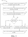
- the process 500 comprises commanding, via a controller 301, a scanner to scan a portion of the IBR 100 (step 502).
- the portion of the IBR 100 may comprise a blade 103 or the like.
- a root, a platform, or the like of the IBR 100 may be the portion. The present disclosure is not limited in this regard.
- the root and the platform of the IBR 100 may be scanned along with the blade 103.
- multiple blades 103 may be scanned with the portion of the IBR 100.
- commanding the scanner 310 in step 502 may further comprise commanding rollers of the curved track 314, commanding a conveyor belt or linkages of the vertical track 316 or the like in conj unction with scanning via the scanner 310.
- the controller 301 may provide a predetermined path for the scanner 310 to scan the portion of the IBR 100, in accordance with various embodiments.
- the process 500 further comprises receiving, via the controller, a three-dimensional model of the first portion of the IBR 100 (step 504).
- the three-dimensional model is a point cloud.
- the scanner 310 measures discrete points of surfaces of the portion of the IBR being scanned and transmits the discrete points to the controller 301.
- the point cloud may be relative to a datum defined by the inspection system 300.
- the shaft 308 may be configured to couple to the IBR 100 being inspected in exactly the same place every time.
- a datum for the inspection system 300 may be defined in the memory 402 of the control system 400.
- the datum is a center point of the IBR 100 (e.g., a center point of the disk of the IBR 100).
- the controller 301 is configured to determine a location of each point scanned via the scanner 310 based on the datum, a location of the scanner 310 when a scan occurs during step 502 from sensor(s) 410, measurement data from the scanner 310, and an angular position of the IBR 100 from sensor(s) 408.
- the process 500 further comprises storing, via the controller 301, the three dimensional model in a database 406 (step 506).
- the scanner 310 may scan the entire IBR prior to transmitting the three-dimensional model to the controller 301 and still be within the scope of this disclosure.
- the controller 301 may be configured to determine an amount of the IBR 100 that has been scanned based on the angular position of the IBR 100 and the position of the scanner 310 throughout step 502.
- the process 500 further comprises determining whether the IBR has been scanned in its entirety (e.g., between 95% and 100% or between 99% and 100% or approximately 100%). In this regard, the process 500 may determine whether the scanner 310 has performed a scan at each predetermined arc angle (e.g., 1 degree, 3 degrees, 5 degrees, or the like) and a total angular rotation of the IBR 100 for the scanning process has reached 360 degrees.
- predetermined arc angle e.g., 1 degree, 3 degrees, 5 degrees, or the like
- the process 500 further comprises commanding, via the controller 301, rotation of the IBR 100 a fixed amount (e.g., 1 degree, 3 degrees, 5 degrees, 10 degrees, etc.) (step 510).
- a fixed amount e.g. 1 degree, 3 degrees, 5 degrees, 10 degrees, etc.
- the controller 301 may command the motor 404 to rotate the IBR 100 the fixed amount, in accordance with various embodiments.
- steps 502, 504, 506, 508 are repeated until the entire IBR is scanned according to step 508, at which point the process 500 further comprises generating, via the controller 301, a three-dimensional model of the IBR 100 (step 512).
- the controller 301 may stitch together the point clouds for each portion of the IBR scanned via step 502 to generate a robust point cloud of the entire IBR 100 (e.g., between 95% and 100% of an external surface area of the IBR 100, or between 99% and 100% of the external surface area of the IBR 100, or approximately 100% of the external surface area of the IBR 100).
- the entire IBR 100 refers to approximately 100% of an external surface area of all the blades of the IBR 100.
- the process 500 further comprises storing, via the controller 301, the three-dimensional model of the IBR in the database 406 (step 514).
- the three dimensional model may be utilized for analyzing the inspected IBR (e.g., in accordance with step 204 of method 200), determining a repair for the inspected IBR (e.g., based on step 204 of method 200) and/or in repairing the inspected IBR (e.g., in accordance with step 206 of method 200).
- the process 500 may provide a fully automated solution for generating a robust three dimensional model (e.g., a point cloud) for an inspected IBR 100, in accordance with various embodiments.
- a robust three dimensional model e.g., a point cloud
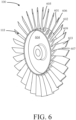
- the IBR 100 comprises a plurality of the blades 103 disposed circumferentially around a platform 602 of the IBR 100.
- the platform 602 may define a radially outer end of a disk 604 of the IBR 100.
- Each blade 103 in the plurality of the blades 103 extends radially outward from the platform 602 from a proximal end at the platform 602 to a distal end 606 (e.g., a tip of the blade 103)
- the blade 103 comprise an airfoil 601.
- blade and airfoil may be used interchangeably herein and still be within the scope of this disclosure.
- the airfoil 601 comprises a pressure side 603, a suction side 605, a leading edge 607 and a trailing edge 609.
- a six-point nest may be determined via a sheath 700 as shown in FIG. 7 by generating six contact points (e.g., with the platform 602, one of the leading edge 607 and the trailing edge 609, and one of the pressure side 603 and the suction side 605 of the airfoil) as described further herein.
- the six-point nest of each airfoil 601 may be determined based on an inspection process as described further herein.
- the inspection process may be configured to generate a second six point nest based on a plurality of locators.
- the inspection system may determine the first six point nest (e.g., within a certain tolerance), and then determine a datum associated with the first six point nest.
- each airfoil 601 may be compared based on a consistent six-point nest with a consistent datum regardless of which inspected IBR the airfoil 601 is on, or which airfoil 601 the airfoil is in the plurality of blades 103 of the inspected IBR 100.
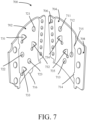
- the sheath 700 for use in the process 500 and the processes described further herein, is illustrated, in accordance with various embodiments.
- the sheath 700 comprises a clamshell (e.g., a first half 702 and a second half 704).
- a clamshell configuration e.g., a first half 702 and a second half 704
- the sheath 700 may be formed of a single-piece (e.g., a monolithic component), and be configured to slide over a blade 103 of an airfoil 601, in accordance with various embodiments.
- the halves 702, 704 of the clamshell are configured to be hingedly coupled proximate a trailing edge 609 of an airfoil 601 of an IBR 100.
- the first half 702 and the second half 704 of the clamshell may be wrapped around the airfoil 601 from the trailing edge 609, the first half 702 and the second half 704 may be pivoted together about a hinge of the clamshell (e.g., disposed at a trailing edge or leading edge of the clamshell).
- a hinge of the clamshell e.g., disposed at a trailing edge or leading edge of the clamshell.
- both a trailing edge end and a leading edge end of the first half 702 may be configured to be coupled to the trailing edge end 706 and the leading edge end 708 of the second half, in accordance with various embodiments.
- the sheath 700 defines a six-point nest for a respective blade 103 of an IBR.
- the sheath 700 comprises a first protrusion 711, a second protrusion 712, a third protrusion 713, a first edge roll 714, a second edge roll, 715 and a fourth protrusion 716.
- the protrusions 711, 712, and 713 may each be configured to contact one of the pressure side 603 or the suction side 605 of the airfoil.
- contact points for the protrusions 711, 712, 713 may define a plane of the six point nest for the respective blade 103, in accordance with various embodiments.
- the edge rolls 714, 715 are configured to contact a leading edge 607 of the airfoil. Although discussed herein as contacting the leading edge 607 of the airfoil 601, the present disclosure is not limited in this regard.
- the edge rolls 714, 715 may be configured to contact the trailing edge 609 of the airfoil 601, a distal end 610 (e.g., a tip) of the airfoil, or the like and still be within the scope of this disclosure.
- contact points for the edge rolls 714, 715 of the sheath define a line of the six-point nest for the respective blade 101 of the IBR 100 being inspected.
- the fourth protrusion 716 is configured to contact the platform 602 of the IBR 100.
- the sixth point of the six-point next may be the contact point between the fourth protrusion 716 and the platform 602.
- an origin of the IBR 100 may be determined.
- the origin may correspond to an origin of a blue print (e.g., a product definition) associated with the IBR 100.
- the six-point nest constrains the airfoil 601 in space in a consistent manner to facilitate consistent comparison between airfoils for an IBR 100 being inspected and/or across a stack of IBRs 110 in a compressor section 24 of a gas turbine engine, in accordance with various embodiments.
- the sheath 700 further comprises protrusions 721, 722, 723.
- the protrusions 721, 722, 723 are configured to interface with an airfoil surface opposite the protrusions 711, 712, 723.
- the protrusions 721, 722, 723 are configured to ensure the protrusions 711, 712, 713 contact the airfoil surface (e.g., a pressure side 603 surface, a suction side 605 surface or the like) by compressing the protrusions 711, 712, 713 against the respective surface in response to coupling the first half 702 to the second half 704.
- the protrusions 721, 722, 723 are configured to interface with the pressure side 603 of the airfoil.
- the protrusions 721, 722, 723 are configured to interface with the suction side 605 of the airfoil 601.
- the sheath 700 further comprises aperture 731, 732, 733, 734, 735.
- three of the apertures e.g., apertures 731, 732, 733 are disposed on a first half 702 and two of the apertures (e.g., apertures 734, 735) are disposed on a second half 704 of the sheath 700.
- apertures 731, 732, 733 are configured to provide access through the sheath 700 to one of a pressure side 603 or a suction side 605 of an airfoil 601 in response to the sheath 700 being coupled to the airfoil.
- apertures 734, 735 are configured to provide access through the sheath 700 to one of the pressure side 603 or the suction side 605 of the airfoil (i.e., an opposite side relative to apertures 731, 732, 733).
- the apertures 731, 732, 733, 734, 735 are configured to facilitate efficient and accurate placement of a locator as described further herein.
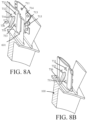
- FIGs. 8A and 8B perspective cut-away view of a sheath 700 being assembled ( FIG. 8A ) and coupled to an airfoil 601 ( FIG. 8B ) is illustrated, with like numerals depicting like elements, in accordance with various embodiments prior to an inspection step 202 of method 200.
- the sheath 700 further comprises an aperture 736 configured to provide access to the platform 602 of the IBR 100.
- six locators may be aligned, and coupled to, the IBR 100 based on the apertures 731, 732, 733, 734, 735, 736 for each airfoil 601 of a respective IBR 100.
- a sheath 700 may be coupled to a airfoil 601, locators may be aligned and coupled to the first airfoil, the sheath 700 may be de-coupled from the airfoil 601, and the process may be repeated until each airfoil has six locators associated with the airfoil 601 to define a position of the airfoil relative to a consistent origin as described further herein, in accordance with various embodiments.
- FIG. 9A a detail view of an aperture 900 of a sheath 700 for aligning and coupling locators to an IBR 100 is illustrated in accordance with various embodiments.
- the apertures 731, 732, 733, 734, 735, 736 are in accordance with the aperture 900.
- the aperture 900 comprises a keyhole shape.
- the aperture may comprise a first side 902 and a second side 904 converging into a non-fully circular aperture 906.
- the non-fully circular aperture 906 may define an arcuate side 907.
- the aperture 900 is disposed through an alignment protrusion 950.
- each aperture in the apertures 731, 732, 733, 734, 735 736 may be disposed through the alignment protrusion 950.
- the alignment protrusion 950 may extend outward (e.g., away from a surface having a locator coupled there to).
- the alignment protrusion 950 may provide additional surface area for the locator to contact in response to aligning and coupling the locator to a surface of an IBR 100 as described further herein.
- the alignment protrusion 950 may facilitate more consistent placement of the locator as described further herein.
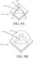
- the locator 1000 may comprise a right triangular pyramid, in accordance with various embodiments. Although illustrated as a right triangular pyramid, the present disclosure is not limited in this regard. For example, a triangular pyramid, square pyramid, a pentagonal pyramid, a rectangular pyramid or the like are all within the scope of this disclosure. In various embodiments a right triangular pyramid may facilitate accurate and consistent placement of the locator 1000 within the apertures 731, 732, 733, 734, 735, 736 of the sheath 700, in accordance with various embodiments.
- the locator comprises a base 1002, a first side 1004, a second side 1006, a third side 1008, and a apex 1010.
- the base 1002 is configured to be coupled to the IBR 100 as described further herein (e.g., via an adhesive or the like).
- the first side 1004 and the second side 1006 are perpendicular to a plane defined by the base 1002.
- the third side 1008 forms an acute angle with a plane defined by the base 1002.
- the first side 1004, the second side 1006, and the third side 1008 intersect at the apex 1010.
- the apex 1010 is designed to be a predetermined distance D1 from the base.
- the locator 1000 may be coupled to an IBR 100 set to be inspected in accordance with step 202 of method 200 through the aperture 900 (e.g., for each aperture in the apertures 731, 732, 733, 734, 735, 736 of the sheath 700), in accordance with various embodiments.
- the locator 1000 may be further aligned via the alignment protrusion 950.
- the aperture 900 may facilitate alignment of the apex 1010 of the locator 1000 approximately with a centerline of the non-fully circular aperture 906. In this regard, the locator 1000 may consistently be disposed accurately and efficiently on the IBR 100.
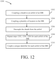
- the method 1200 comprises coupling a sheath 700 to an airfoil 601 of an IBR 100 (step 1202) and coupling a plurality of locators 1000 to the IBR 100.
- the plurality of locators 1000 may include six locators. Although described herein as comprising six locators, the present disclosure is not limited in this regard.
- three locators may be utilized to form an over constrained six point nest (e.g., one point is part of a plane, a line, and a point of the six-point nest, a second point is a part of the plane and the line, and a third point is a part of the plane).
- at least three locators may be desirable for forming a six-point nest to define a location of the airfoil 601 in space as defined further herein.
- six locators 1000 by using six locators 1000 a more robust and accurate location of the airfoil 601 may be determined, in accordance with various embodiments.
- coupling the plurality of locators in step 1204 may include adhering a base 1002 of each locator 1000 to an external surface of the IBR 100 (e.g., a pressure side 603 surface, a suction side 605 surface, a platform 602 surface, or the like).
- the base may be aligned on the respective external surface of the IBR 100 via an aperture 900 disposed through the sheath 700.
- the aperture 900 may be keyhole shaped as described further herein.
- an alignment protrusion 950 may further facilitate accurate placement of the locator 1000, in accordance with various embodiments.
- the method 1200 may further comprise de-coupling the sheath from the airfoil (step 1206) and repeating steps 1202, 1204, 1206 for each airfoil 601 of the IBR 100 (step 1208).
- each airfoil may be associated with six locators.
- the method 1200 further comprises coupling a unique identifier to each airfoil of the IBR 100 (step 1210).
- a first airfoil may determine a first clocked position (e.g., 0 degrees), and each airfoil may be clocked relative to the first airfoil.
- the IBR analysis system from step 204 of method 200 may factor in repair shapes of one airfoil and its effect on other airfoils, of the same IBR or other IBRs in a stack of inspected IBRs, in accordance with various embodiments.
- a top dead center of the IBR may be delineated based on the unique identifiers, which may provide an additional reference point for comparison purposes in an analysis step 204 of method 200.
- all airfoils that have been inspected and repaired and stored in the database 406 may be accessible for comparison purposes in the analysis step 204 of method 200 for determining a respective repair for the IBR 100.
- the process 1300 comprises commanding, via a controller 301, a scanner 310 to scan an airfoil of an IBR 100 after locators were disposed thereon in accordance with method 1200 (step 1302).
- the process 1300 further comprises receiving, via the controller 301 and from the scanner 310, a point cloud of the airfoil 601 (step 1304).
- the scanner 310 may comprise a CMM scanner or a blue light scanner.
- the scanner 310 comprises a blue light scanner.
- the process 1300 further comprises determining, via the controller 301, an apex 1010 of each locator 1000 associated with the airfoil 601 based on the point cloud (step 1306).
- the scanner 310 may receive discrete points in the point cloud of each side surface of the locator 1000 (e.g., sides 1004, 1006, 1008).
- the controller can determine, based on at least three discrete points on each side (or averaging any number of points on each side), a plane for each side.
- the controller can further determine an intersection of each plane for each side (e.g., sides 1004, 1006, 1008), which is the apex 1010.
- the controller 301 can determine the apex of each locator 1000 (step 1308).
- the controller 301 can generate a first six point nest of the airfoil 601 based on the apex of each locator (step 1310).
- the process 1300 further comprises generating, via the controller 301, a second six point nest of the airfoil 601 based on the first six point nest (step 1312).
- a reference frame of the airfoil 601 may be unambiguously defined.
- the reference frame of the airfoil 601 based on the locator has a distinct spatial relation to the six-point nest defined by the protrusions 711, 712, 713, 716 and edge rolls 714, 715 of the sheath 700.
- the six point nest of the protrusions 711, 712, 713, 716 and edge rolls 714, 715 of the sheath 700 may be constrained relative to an origin corresponding an origin of a design for the IBR being inspected.
- the six point nest defined by the protrusions 711, 712, 713, 716 and edge rolls 714, 715 of the sheath 700 may correspond to an origin which defines a product definition for the IBR being inspected.
- the IBR analysis system may overlay airfoil based on the second six point nest and have a direct comparison of variations between airfoils.
- potential repairs may be compared, repairs effects on vibratory characteristics may be compared, past repairs effects on vibratory characteristics may be compared, airfoils of the same inspected IBR may be compared, or the like.
- the present disclosure is not limited in this regard.
- references to "one embodiment,” “an embodiment,” “various embodiments,” etc. indicate that the embodiment described may include a particular feature, structure, or characteristic, but every embodiment may not necessarily include the particular feature, structure, or characteristic. Moreover, such phrases are not necessarily referring to the same embodiment. Further, when a particular feature, structure, or characteristic is described in connection with an embodiment, it is submitted that it is within the knowledge of one skilled in the art to affect such feature, structure, or characteristic in connection with other embodiments whether or not explicitly described. After reading the description, it will be apparent to one skilled in the relevant art(s) how to implement the disclosure in alternative embodiments.
- Numbers, percentages, or other values stated herein are intended to include that value, and also other values that are about or approximately equal to the stated value, as would be appreciated by one of ordinary skill in the art encompassed by various embodiments of the present disclosure.
- a stated value should therefore be interpreted broadly enough to encompass values that are at least close enough to the stated value to perform a desired function or achieve a desired result.
- the stated values include at least the variation to be expected in a suitable industrial process, and may include values that are within 10%, within 5%, within 1%, within 0.1 %, or within 0.01% of a stated value.
- the terms “substantially,” “about” or “approximately” as used herein represent an amount close to the stated amount that still performs a desired function or achieves a desired result.
- the term “substantially,” “about” or “approximately” may refer to an amount that is within 10% of, within 5% of, within 1% of, within 0.1 % of, and within 0.01% of a stated amount or value.
Landscapes
- Engineering & Computer Science (AREA)
- Mechanical Engineering (AREA)
- Physics & Mathematics (AREA)
- General Engineering & Computer Science (AREA)
- General Physics & Mathematics (AREA)
- Theoretical Computer Science (AREA)
- Robotics (AREA)
- Evolutionary Computation (AREA)
- Geometry (AREA)
- Quality & Reliability (AREA)
- Computer Vision & Pattern Recognition (AREA)
- Computer Hardware Design (AREA)
- Ceramic Engineering (AREA)
- Structures Of Non-Positive Displacement Pumps (AREA)
- Turbine Rotor Nozzle Sealing (AREA)
Applications Claiming Priority (1)
| Application Number | Priority Date | Filing Date | Title |
|---|---|---|---|
| US17/702,519 US20230306163A1 (en) | 2022-03-23 | 2022-03-23 | Inspection systems and methods with airfoil sheaths |
Publications (2)
| Publication Number | Publication Date |
|---|---|
| EP4249845A2 true EP4249845A2 (fr) | 2023-09-27 |
| EP4249845A3 EP4249845A3 (fr) | 2024-01-10 |
Family
ID=85380833
Family Applications (1)
| Application Number | Title | Priority Date | Filing Date |
|---|---|---|---|
| EP23158302.2A Pending EP4249845A3 (fr) | 2022-03-23 | 2023-02-23 | Systèmes et procédés d'inspection avec gaines de profil aérodynamique |
Country Status (2)
| Country | Link |
|---|---|
| US (1) | US20230306163A1 (fr) |
| EP (1) | EP4249845A3 (fr) |
Family Cites Families (4)
| Publication number | Priority date | Publication date | Assignee | Title |
|---|---|---|---|---|
| US7024787B2 (en) * | 2004-04-01 | 2006-04-11 | United Technologies Corporation | Template for evaluating parts and method of using same |
| US8621761B2 (en) * | 2011-12-30 | 2014-01-07 | United Technologies Corporation | Self identifying template gage probing system |
| FR2987296B1 (fr) * | 2012-02-23 | 2014-12-19 | Snecma | Dispositif de controle de percages d'evacuation de l'air de refroidissement d'une aube de turbine a gaz |
| US9733195B2 (en) * | 2015-12-18 | 2017-08-15 | General Electric Company | System and method for inspecting turbine blades |
-
2022
- 2022-03-23 US US17/702,519 patent/US20230306163A1/en active Pending
-
2023
- 2023-02-23 EP EP23158302.2A patent/EP4249845A3/fr active Pending
Also Published As
| Publication number | Publication date |
|---|---|
| US20230306163A1 (en) | 2023-09-28 |
| EP4249845A3 (fr) | 2024-01-10 |
Similar Documents
| Publication | Publication Date | Title |
|---|---|---|
| CA2444921C (fr) | Systemes et methodes de detection et d'usinage automatiques pour reparer les profils aerodynamiques de pales | |
| EP1760427B1 (fr) | Procédés de mesure de la zone de flux entre les aubes fixes d'une turbine à gaz | |
| EP4258073A1 (fr) | Systèmes et procédés de réparation partielle pour rotors à aubage intégral | |
| EP4257804A1 (fr) | Systèmes et procédés d'analyse du désaccord pour la réparation de rotors à aubes inspectées | |
| EP4258074A1 (fr) | Systèmes et procédés d'analyse aérodynamique de rotors à pales contrôlés | |
| EP4249845A2 (fr) | Systèmes et procédés d'inspection avec gaines de profil aérodynamique | |
| EP4249727A2 (fr) | Montage d'outil à profil aérodynamique | |
| EP4269753A1 (fr) | Systèmes et procédés d'inspection pour sceller des surfaces | |
| EP4249898A1 (fr) | Systèmes et procédés d'inspection de double scanner | |
| US20230304943A1 (en) | Multi-stage inspection systems and methods | |
| EP4249900A1 (fr) | Systèmes et procédés d'inspection à rétroaction | |
| US11860060B2 (en) | Integrally bladed rotor analysis and repair systems and methods | |
| EP4257799A1 (fr) | Systèmes et procédés d'inspection, d'analyse et de réparation de rotor à pales | |
| EP4258075A1 (fr) | Systèmes et procédés de paramétrage d'analyse de rotor à aubes contrôlée | |
| EP4257798A1 (fr) | Systèmes et procédés de réparation basés sur une pile | |
| EP4257282A1 (fr) | Systèmes et procédés de génération de modèles de réparation de mélange | |
| EP4257283A2 (fr) | Systèmes et procédés d'inspection et d'analyse basés sur une approche de mélange | |
| EP4257803A1 (fr) | Systèmes et procédés de transfert pour fournier de données entrées d'analyse de reparation | |
| EP4257801A1 (fr) | Systèmes et procédés d'analyse des réparations pour rotors à aubes inspectées | |
| EP4257802A1 (fr) | Système et procédé d'analyse des réparations structurale pour rotors à aubes inspectées | |
| EP4375486A2 (fr) | Systèmes et procédés de gestion de données d'inspection | |
| US20240139892A1 (en) | A method of manufacturing a turbomachinery component |
Legal Events
| Date | Code | Title | Description |
|---|---|---|---|
| PUAI | Public reference made under article 153(3) epc to a published international application that has entered the european phase |
Free format text: ORIGINAL CODE: 0009012 |
|
| STAA | Information on the status of an ep patent application or granted ep patent |
Free format text: STATUS: THE APPLICATION HAS BEEN PUBLISHED |
|
| AK | Designated contracting states |
Kind code of ref document: A2 Designated state(s): AL AT BE BG CH CY CZ DE DK EE ES FI FR GB GR HR HU IE IS IT LI LT LU LV MC ME MK MT NL NO PL PT RO RS SE SI SK SM TR |
|
| RAP3 | Party data changed (applicant data changed or rights of an application transferred) |
Owner name: RTX CORPORATION |
|
| PUAL | Search report despatched |
Free format text: ORIGINAL CODE: 0009013 |
|
| AK | Designated contracting states |
Kind code of ref document: A3 Designated state(s): AL AT BE BG CH CY CZ DE DK EE ES FI FR GB GR HR HU IE IS IT LI LT LU LV MC ME MK MT NL NO PL PT RO RS SE SI SK SM TR |
|
| RIC1 | Information provided on ipc code assigned before grant |
Ipc: G01B 3/14 20060101AFI20231204BHEP |