EP4249825A1 - Cap element with buffer channels - Google Patents
Cap element with buffer channels Download PDFInfo
- Publication number
- EP4249825A1 EP4249825A1 EP22163167.4A EP22163167A EP4249825A1 EP 4249825 A1 EP4249825 A1 EP 4249825A1 EP 22163167 A EP22163167 A EP 22163167A EP 4249825 A1 EP4249825 A1 EP 4249825A1
- Authority
- EP
- European Patent Office
- Prior art keywords
- cap element
- casing
- buffer
- buffer channel
- channel
- Prior art date
- Legal status (The legal status is an assumption and is not a legal conclusion. Google has not performed a legal analysis and makes no representation as to the accuracy of the status listed.)
- Withdrawn
Links
Images


Classifications
-
- F—MECHANICAL ENGINEERING; LIGHTING; HEATING; WEAPONS; BLASTING
- F24—HEATING; RANGES; VENTILATING
- F24H—FLUID HEATERS, e.g. WATER OR AIR HEATERS, HAVING HEAT-GENERATING MEANS, e.g. HEAT PUMPS, IN GENERAL
- F24H4/00—Fluid heaters characterised by the use of heat pumps
- F24H4/02—Water heaters
- F24H4/04—Storage heaters
-
- F—MECHANICAL ENGINEERING; LIGHTING; HEATING; WEAPONS; BLASTING
- F24—HEATING; RANGES; VENTILATING
- F24H—FLUID HEATERS, e.g. WATER OR AIR HEATERS, HAVING HEAT-GENERATING MEANS, e.g. HEAT PUMPS, IN GENERAL
- F24H1/00—Water heaters, e.g. boilers, continuous-flow heaters or water-storage heaters
- F24H1/18—Water-storage heaters
- F24H1/181—Construction of the tank
-
- F—MECHANICAL ENGINEERING; LIGHTING; HEATING; WEAPONS; BLASTING
- F24—HEATING; RANGES; VENTILATING
- F24H—FLUID HEATERS, e.g. WATER OR AIR HEATERS, HAVING HEAT-GENERATING MEANS, e.g. HEAT PUMPS, IN GENERAL
- F24H1/00—Water heaters, e.g. boilers, continuous-flow heaters or water-storage heaters
- F24H1/18—Water-storage heaters
- F24H1/181—Construction of the tank
- F24H1/182—Insulation
Definitions
- the invention relates to a cap element for a heating device and to a heating device system comprising said cap element. Also, the invention relates to a use of said cap element in a heating device system.
- a heating device like a heat pump is a device able to warm a closed space of a building or to warm domestic hot water by transferring thermal energy from a source to another.
- An air-source heat pump water heater is a device using the heat pump technology to use energy from air to heat the domestic water contained in a tank.
- a hot water tank for the production of hot water for heating or domestic hot water is composed of two main elements: a tank and a thermal insulation.
- the thermal insulation is usually achieved by one of two means: the installation of parts around the tank (adhesive foam parts, adhesive insulation etc.) or the injection of insulating foam into an outer casing.
- Insulating foam injection is achieved by injecting chemical components that react together via a chemical reaction. This chemical reaction causes the solid produced to expand to such an extent that the volume of foam obtained is much greater than the volume of the components injected separately.
- the injection process is a complex one and many factors create variability in the volume required and the volume injected, i.e., tank geometry tolerance, casing geometry tolerance, ambient air temperature, temperature of the chemical components of the insulation, concentration of the components, nature of the components, precision of the injection machine, etc.
- the product can end up with a lack of insulating foam (reduced thermal performance and deformation of the casing) or an excess of insulating foam (aesthetic degradation and constraint for the assembly of the other components).
- the mastery of the insulation injection process is therefore a major element that allows the production of a high-performance and functional device.
- vents serve to evacuate the gases produced during the chemical reaction of the insulating foam.
- several vents are provided (two to sixteen in general) and are positioned in a distributed way on the high points of the injected zone. They are made by small diameter holes (generally in the order of 1 to 3 mm) in the thin cap (generally in the order of 1 to 2.5 mm). Even with a mastered industrial process, it is empirically identified that the variability of the various elements is generally between 2 cm 3 and 30 cm 3 . In order to avoid a lack of thermal performance and deformation of the case, it is accepted that the products are over-injected and the excess material is removed when it is too large.
- a cap element for a heating device including a water tank located in a casing, wherein the cap element is placeable in or on the casing for closing said casing, the cap element comprising: at least a buffer channel extending through a cap element material from a first surface to a second surface of the cap element, the second surface facing the water tank, wherein the buffer channel (5) has a volume in the range between 0,5 cm 3 to 20 cm 3 , in particular 0,5 cm 3 to 12 cm 3 , in particular 2 cm 3 to 8 cm 3 .
- the cap element can be a top element of the casing or can be any other closing element located for example at the base or at the side of the casing.
- the cap element can be the aesthetic top cap of a product or the base of other components, in particular the base of a heat pump in the case of a water heater.
- the product can be assembled (at least partially) upside down. In that case, the buffer channel will be at the top during insulation phase but at the bottom in its installation position.
- the buffer channel in the cap element allows to buffer and compensate for injection volume differences when insulating the water tank with a specific material, such as foam.
- the excess of insulating material can be received by the buffer channel by entering the inlet opening that is located on the surface of the cap element facing the water tank, i.e. the surface facing the internal space of the casing that is filled with the insulating material.
- the dimension of the cross sectional area of the buffer channel allows a collection of a great amount of excess of insulating material, thereby avoiding the problem related to a refinement of foam due to over-injection.
- the buffer channel can be advantageously integrated into moulded parts, particularly for injected or expanded parts of the cap element.
- the dimensions are compatible with the injection moulding tools. Thanks to the presence of these buffer channels, the presence of foam balls is avoided on the aesthetic or functional parts of the outer part of the cap element, thereby also avoiding production rejects.
- a cross sectional area of the buffer channel is greater than 10 mm 2 and in particular ranges between 10 mm 2 and 115 mm 2 .
- the inlet opening is circular having a diameter comprised between 3 and 13 mm, preferably between 11 mm and 13 mm, in particular 12 mm.
- This dimension is sensibly larger than the dimensions of the inlet openings of prior art vents.
- the dimension on the inlet opening of the buffer channel is almost 4 times bigger than that of prior art vents.
- prior art vents are basically used for gas discharge.
- the inlet opening can have a different shape.
- the inlet opening can have a polygonal shape, an elliptical shape or any shape suitable for receiving the insulation material.
- the cross sectional area can be comprised between 90 mm 2 and 135 mm 2 , in particular 115 mm 2 .
- the buffer channel comprises an outlet opening located on the first surface for venting gases produced in a space between the water tank and the casing upon generation of an insulating material in said space.
- the outlet opening is located on the surface of the cap element material facing outside the casing. Accordingly, the buffer channel acts both as a vent during the curing of the foam and as a buffer zone to compensate for excess foam.
- the buffer channel allows a visual control of the injection by looking at the outside of the channel. Also, it ensures a good venting of the product during the chemical reaction of polymerisation. In addition, thanks to the size of the cross section of the channel, it is possible to check the fulfilling of the product thanks to an indicating tool, for example a graduated needle that indicates the level of foam filling.
- the outlet opening is circular having a diameter comprised between 3 and 10 mm, preferably between 8 mm and 10 mm, in particular 9 mm.
- the outlet opening can have a different shape.
- the outlet opening can have a polygonal shape, an elliptical shape or any shape suitable for discharging gas.
- the cross sectional area can be comprised between 50 mm 2 and 80 mm 2 , in particular 65 mm 2 .
- the inlet opening is larger than the outlet opening. Due to the different functions of the openings, the inlet opening being suitable for receiving the insulation material (and also the gas produced in the casing) and the outlet opening being essentially suitably only for discharging the gas, it is important that the inlet opening be larger than the outlet opening. In this way, a great quantity of excess of insulation material can pass through the inlet opening and eventually be buffered inside the channel without exiting the outlet opening.
- the buffer channel has a circular cross-section, The absence of corners or cavities inside the channels can favour the insertion of the insulating material.
- the buffer channel extends linearly from the first surface to the second surface of the cap element material. In other words, the channel extends straight without deviations passing through the cap element.
- the channel can be provided with one or more internal corners.
- the buffer channel comprises an inlet portion, an outlet portion, and a central portion arranged between the inlet portion and the outlet portion, wherein the cross- section from the inlet portion to the outlet portion through the buffer channel is variable.
- a variable cross-section for example a reduction of the cross-section passing from the inlet opening to the outlet opening ensures that the insulating material, when inserted into the channel from the inlet opening and proceeding through the channel, is subjected to an increased surface force derived from the internal walls of the buffer channel so that movement of the insulating material through the channel is progressively slowed down until it stops inside the channel without exiting the outlet opening.
- the inlet portion is formed as an indentation in the cap element material.
- the outlet portion is formed as an indentation in the cap element material.
- the central portion fluidically connects the inlet portion with the outlet portion.
- the cross-section of the central portion can be smaller than the cross-section of the inlet portion and/or the cross- section of the outlet portion.
- the cross-section of the central portion can be smaller along its extension, in particular along its full extension, along a length axis of a heating device when the cap element is placed on the heating device than the cross-section of the inlet portion and/or the cross-section of the outlet portion.
- the inlet portion can have a funnel-shaped structure
- the outlet portion can have a funnel-shaped structure
- the central portion can have a cylindrical-shaped structure.
- This particular funnel-shaped or conical structure of the inlet portion has the advantage of facilitating the guiding of the insulating material.
- the particular funnel-shaped or conical structure of the outlet portion has the advantage of facilitating the gas discharge.
- the cross-section of the buffer channel decreases in the inlet portion, is constant in the central portion, and increases in the outlet portion.
- the inlet portion is longer than the outlet portion. In this way, the insulating material can easily be buffered in the inlet portion.
- the cap element can comprises at least two buffer channels, wherein the at least two buffer channels have a total volume of at least 2 cm 3 , in particular at least 4 cm 3 .
- a total volume of all buffer channels (5) of the cap element (1) can be between 0.5 cm 3 to 300 cm 3 , in particular 1 cm 3 to 300 cm 3 .
- This particular volume of the buffer channels ensures the correct filling of insulating foam in a product. It avoids any mechanical control or rework action to remove the insulating foam overflow as long as the overflow is within the range compatible with the chosen definition.
- the cap element in order to evenly distribute the pressure exerted by the insulating material on the cap element, can comprise a plurality buffer channels, the plurality of buffer channels being evenly distributed in the cap element.
- a heating device in particular a heat pump water heater, the heating device comprising:
- the cap element comprises at least a buffer channel, in particular having a cross sectional area of the buffer channel greater than 10 mm 2 and in particular ranging between 10 mm 2 and 115 mm 2 and having an inlet opening configured to receive excess of insulating material coming from the space upon generation of said insulating material in said space.
- inventive cap element is used in a heating device, in particular a heat pump water heater.
- FIGs 1A-1C illustrate a heating device system comprising a heating device 2.
- the heating device in particular an insulated heat pump water heater, has a heat pump 16 located on the top of a casing 4 and a water tank 3 located inside the casing 4 below the heat pump 16.
- the heat pump 16 is supported by a cap element 1 of the heating device system wherein the cap element 1 serves as top closing element of the casing 4.
- the heat pump components are arranged on the cap element 1, in particular on a cap element material 19 of the cap element 1.
- the device 2 can be provided with an external cap 17 coupable with the casing 4 to cover the heat pump 16.
- Figure 1B is a cross section of figure 1A
- figure 1C is a cross section of figure 1A without the heat pump 16 located on the cap element 1.
- the insulated heat pump water heater 2 has a water tank 3 located in the casing assembly 4 and an insulating material 7 injected in the space 8 between the tank 3 and the casing 4.
- the casing assembly 4 consists of at least a top, a bottom and a periphery, the positions being at the time of the injection station of an insulating material (e.g. foam) 7.
- the upper part of the casing 4 is provided with a cap element 1 incorporating at least two buffer channels 5 (not shown in the figure).
- the buffer channels 5 act as vents to allow gas to escape during the polymerisation reaction of the insulation and as buffer regions to compensate for excess foam.
- the buffer channels 5 have an inlet opening 6 on the injection side (upper portion 12 of the tank 3) and an outlet opening on the other side of the top of the casing 4.
- the insulating material 7 fills the space 8 between the water tank 3 and the casing 4, the excess of insulating material 7 can be received by the buffer channels 5 through the inlet opening 6.
- a detailed description of the structure of the buffer channel 5 is shown in figures 2A-2B as well as in figures 3A-3B .
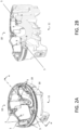
- FIG 2A shows a perspective top view of the cap element 1.
- the cap element 1 has a first surface 10 and a second surface 11. It is noted that this cap element 1, on the first surface 10, is the support for a heat pump 16. As a matter of fact, a dedicated seat for the heat exchanger and a dedicated seat for the fan element 18 are provided on the first surface 10.
- the cap element 1 comprises a plurality of buffer channels 5.
- Figure 2A shows the presence of seven buffer channels 5. These channels 5 are through-holes extending from the first surface 10 to the second surface 11 of the cap element material 19.
- the buffer channels 5 are basically distributed on the edge of the cap element 5. However, some of the buffer channels 5 are also provided in other locations, for example close to the seat of the fan element 18.
- Figure 2B illustrates a cross section of the cap element 1 of figure 2A along the line A-A.
- the buffer channels 5 (encircled in the figure) provide a passage through portions of the cap element material 19 from the second surface 11 to the first surface 10.
- Figures 3A and 3B illustrate in detail the shape of the maximum insulating material 7 stuck in the buffer channel 5 ( Fig. 3A ) and the shape of a buffer channel 5 present in a cap element 1 ( Fig. 3B ).
- the channel 5 has a longitudinal structure comprising an inlet portion 13, the inlet portion 13 being provided with a circular inlet opening 6, an outlet portion 14, the outlet portion 14 being provided with a circular outlet opening 9, and a central portion 15 connecting the inlet portion 13 to the outlet portion 14.
- the portions of the buffer channel 5 are shown with reference to figure 3A for clarity reasons.
- the central portion 15 has a cylindrical shape, whereas both the inlet portion 1 and the outlet portion 14 have a conical or funnel-like shape.
- circular inlet opening 6 has a larger diameter than the circular outlet opening 9 and that the funnel-shape structure of the inlet portion 13 is oriented opposite to the funnel-shape structure of the outlet portion 14.
- the cross section at the outlet opening 9 is larger than the cross section at the corresponding conjunction point with the central portion 15 and the cross section at the inlet opening 6 is larger than the cross section at the corresponding conjunction point with the central portion 15.
- the inlet portion 13 is longer that the outlet portion 14, in particular, the inlet portion 13 can be six times longer than the outlet portion 14.
- the inlet portion 13 can have a length comprised between 14 mm and 16 mm, in particular 15 mm, whereas the outlet portion 14 can have a length comprised between 2 mm and 3 mm, in particular 2.5 mm.
- the particular relationship between dimensions of the inlet portion 13 and the outlet portion 14 makes the buffer channel 5 more efficient in buffering insulating material 7.
- the central portion 15 can have a length comprised between 22 mm and 23 mm, in particular 22.5 mm. Accordingly, the total length of the buffer channel 5 can be comprised between 38mm and 42 mm, in particular 40 mm.
- the ratio between the length of the central portion 15 and the total length of the channel 5 is comprised between 0.55 and 0.57, in particular 0.56. In other words, more than half of the total length of the buffer channel 5 is constituted by the central portion 15.
- Figure 3B illustrates the functioning of the buffer channel 5 as gas vent and as buffer volume.
- the buffer channel 5 is located between the first surface 10 and the second surface 11 of the cap element 1, thereby forming a straight through-channel.
- the inlet opening 6 is located on the second surface 11 facing the water tank 3, in particular the upper portion 12 of the tank 3.
- the outlet opening 9 is located on the first surface 10 opposite the second surface 11 and facing outside the casing 4.
- the gas can easily be discharged outside passing from the inlet opening 6, through the inlet portion 13, the central portion 15, the outlet portion 14, and exiting the outlet opening 9.
- the excess of insulating material 7 can be received by the buffer channel 5, in particular by the inlet portion 13 of the buffer channel 5. In this way, excess of insulating material 7 is buffered in the channel 5, thereby avoiding the problem related to a refinement of foam due to over-injection.
- the presence of an inlet opening 6 and outlet opening 9 along a straight longitudinal structure allows visible accessibility from outside for inspection inside the casing 4 as well as the possibility of inserting an indicating tool for checking the fulfilling of the product.
- Each of the buffer channels 5 discussed above has a volume in the range between 0,5 cm 3 to 20 cm 3 , in particular 0,5 cm 3 to 12 cm 3 , in particular 1 cm 3 to 8 cm 3 for receiving foam.
Landscapes
- Engineering & Computer Science (AREA)
- Physics & Mathematics (AREA)
- Thermal Sciences (AREA)
- Chemical & Material Sciences (AREA)
- Combustion & Propulsion (AREA)
- Mechanical Engineering (AREA)
- General Engineering & Computer Science (AREA)
- Thermal Insulation (AREA)
Abstract
Cap element (1) for a heating device (2), the heating device (2) including a water tank (3) located in a casing (4), wherein the cap element (1) is placeable in or on the casing (4) for closing said casing (4), the cap element (1) comprising:at least a buffer channel (5) extending through the cap element (1) from a first surface (10) to a second surface (11) of the cap element (1), the second surface (11) facing the water tank (3), wherein the buffer channel (5) has a volume in the range between 0,5 cm<sup>3</sup> to 20 cm<sup>3</sup>, in particular 0,5 cm<sup>3</sup> to 12 cm<sup>3</sup>, in particular 1 cm<sup>3</sup> to 8 cm<sup>3</sup>.
Description
- The invention relates to a cap element for a heating device and to a heating device system comprising said cap element. Also, the invention relates to a use of said cap element in a heating device system.
- A heating device like a heat pump is a device able to warm a closed space of a building or to warm domestic hot water by transferring thermal energy from a source to another. An air-source heat pump water heater is a device using the heat pump technology to use energy from air to heat the domestic water contained in a tank.
- A hot water tank for the production of hot water for heating or domestic hot water is composed of two main elements: a tank and a thermal insulation. The thermal insulation is usually achieved by one of two means: the installation of parts around the tank (adhesive foam parts, adhesive insulation etc.) or the injection of insulating foam into an outer casing. Insulating foam injection is achieved by injecting chemical components that react together via a chemical reaction. This chemical reaction causes the solid produced to expand to such an extent that the volume of foam obtained is much greater than the volume of the components injected separately.
- The injection process is a complex one and many factors create variability in the volume required and the volume injected, i.e., tank geometry tolerance, casing geometry tolerance, ambient air temperature, temperature of the chemical components of the insulation, concentration of the components, nature of the components, precision of the injection machine, etc.
- As a result, the product can end up with a lack of insulating foam (reduced thermal performance and deformation of the casing) or an excess of insulating foam (aesthetic degradation and constraint for the assembly of the other components). The mastery of the insulation injection process is therefore a major element that allows the production of a high-performance and functional device.
- At present, this control requires a significant follow-up in production and it is commonly used to carry out an over-injection and to remove by a mechanical action the overflow of foam.
- When water heaters are thermally insulated by injecting foam insulation between the casing and the tank, generally the cap at the top of the casing is provided with several vents. The vents serve to evacuate the gases produced during the chemical reaction of the insulating foam. In general, several vents are provided (two to sixteen in general) and are positioned in a distributed way on the high points of the injected zone. They are made by small diameter holes (generally in the order of 1 to 3 mm) in the thin cap (generally in the order of 1 to 2.5 mm). Even with a mastered industrial process, it is empirically identified that the variability of the various elements is generally between 2 cm3 and 30 cm3. In order to avoid a lack of thermal performance and deformation of the case, it is accepted that the products are over-injected and the excess material is removed when it is too large.
- It is therefore desirable to obtain a way to efficiently thermally isolate the water tank with foam injection without the necessity of follow-up in the production.
- The object is solved by a cap element for a heating device, the heating device including a water tank located in a casing, wherein the cap element is placeable in or on the casing for closing said casing, the cap element comprising:
at least a buffer channel extending through a cap element material from a first surface to a second surface of the cap element, the second surface facing the water tank, wherein the buffer channel (5) has a volume in the range between 0,5 cm3 to 20 cm3, in particular 0,5 cm3 to 12 cm3, in particular 2 cm3 to 8 cm3. - The cap element can be a top element of the casing or can be any other closing element located for example at the base or at the side of the casing. In particular, the cap element can be the aesthetic top cap of a product or the base of other components, in particular the base of a heat pump in the case of a water heater. It is noted that in case the cap element is not located on the top of the casing but for example at the base, the product can be assembled (at least partially) upside down. In that case, the buffer channel will be at the top during insulation phase but at the bottom in its installation position.
- Advantageously, the buffer channel in the cap element allows to buffer and compensate for injection volume differences when insulating the water tank with a specific material, such as foam. The excess of insulating material can be received by the buffer channel by entering the inlet opening that is located on the surface of the cap element facing the water tank, i.e. the surface facing the internal space of the casing that is filled with the insulating material. In particular, compared to the prior art vents present in the top cap of the casing used for gas escaping, the dimension of the cross sectional area of the buffer channel allows a collection of a great amount of excess of insulating material, thereby avoiding the problem related to a refinement of foam due to over-injection.
- The buffer channel can be advantageously integrated into moulded parts, particularly for injected or expanded parts of the cap element. The dimensions are compatible with the injection moulding tools. Thanks to the presence of these buffer channels, the presence of foam balls is avoided on the aesthetic or functional parts of the outer part of the cap element, thereby also avoiding production rejects.
- According to an example, a cross sectional area of the buffer channel is greater than 10 mm2 and in particular ranges between 10 mm2 and 115 mm2. the inlet opening is circular having a diameter comprised between 3 and 13 mm, preferably between 11 mm and 13 mm, in particular 12 mm. This dimension is sensibly larger than the dimensions of the inlet openings of prior art vents. In particular, the dimension on the inlet opening of the buffer channel is almost 4 times bigger than that of prior art vents. As a matter of fact, prior art vents are basically used for gas discharge. Even if in principle a quantity of insulating material could be pushed into the prior art vents during the foam injection, this quantity would be very limited and would not help to eliminate the problem related to a refinement of foam due to over-injection. In addition, the typical density of the insulating material, such as foam, would prevent a smooth passage of the insulating material into a small inlet opening, such as that of prior art vents.
- The inlet opening can have a different shape. For example, the inlet opening can have a polygonal shape, an elliptical shape or any shape suitable for receiving the insulation material. In particular, the cross sectional area can be comprised between 90 mm2 and 135 mm2, in particular 115 mm2.
- In another example, the buffer channel comprises an outlet opening located on the first surface for venting gases produced in a space between the water tank and the casing upon generation of an insulating material in said space. In other words, the outlet opening is located on the surface of the cap element material facing outside the casing. Accordingly, the buffer channel acts both as a vent during the curing of the foam and as a buffer zone to compensate for excess foam.
- In addition, the buffer channel allows a visual control of the injection by looking at the outside of the channel. Also, it ensures a good venting of the product during the chemical reaction of polymerisation. In addition, thanks to the size of the cross section of the channel, it is possible to check the fulfilling of the product thanks to an indicating tool, for example a graduated needle that indicates the level of foam filling.
- In one example, the outlet opening is circular having a diameter comprised between 3 and 10 mm, preferably between 8 mm and 10 mm, in particular 9 mm. The outlet opening can have a different shape. For example, the outlet opening can have a polygonal shape, an elliptical shape or any shape suitable for discharging gas. In particular, the cross sectional area can be comprised between 50 mm2 and 80 mm2, in particular 65 mm2.
- In another example, the inlet opening is larger than the outlet opening. Due to the different functions of the openings, the inlet opening being suitable for receiving the insulation material (and also the gas produced in the casing) and the outlet opening being essentially suitably only for discharging the gas, it is important that the inlet opening be larger than the outlet opening. In this way, a great quantity of excess of insulation material can pass through the inlet opening and eventually be buffered inside the channel without exiting the outlet opening.
- In an additional example, the buffer channel has a circular cross-section, The absence of corners or cavities inside the channels can favour the insertion of the insulating material.
- In order to avoid hindrances for buffering the insulating material in the channel, the buffer channel extends linearly from the first surface to the second surface of the cap element material. In other words, the channel extends straight without deviations passing through the cap element. However, to increase the buffering volume of the channel, the channel can be provided with one or more internal corners.
- In another example, the buffer channel comprises an inlet portion, an outlet portion, and a central portion arranged between the inlet portion and the outlet portion, wherein the cross- section from the inlet portion to the outlet portion through the buffer channel is variable. This particular configuration allows a more efficient use of the buffer channel. As a matter of fact, a variable cross-section, for example a reduction of the cross-section passing from the inlet opening to the outlet opening ensures that the insulating material, when inserted into the channel from the inlet opening and proceeding through the channel, is subjected to an increased surface force derived from the internal walls of the buffer channel so that movement of the insulating material through the channel is progressively slowed down until it stops inside the channel without exiting the outlet opening. The inlet portion is formed as an indentation in the cap element material. Likewise, the outlet portion is formed as an indentation in the cap element material. The central portion fluidically connects the inlet portion with the outlet portion.
- The cross-section of the central portion can be smaller than the cross-section of the inlet portion and/or the cross- section of the outlet portion. In particular, the cross-section of the central portion can be smaller along its extension, in particular along its full extension, along a length axis of a heating device when the cap element is placed on the heating device than the cross-section of the inlet portion and/or the cross-section of the outlet portion.
- In particular, the inlet portion can have a funnel-shaped structure, the outlet portion can have a funnel-shaped structure and the central portion can have a cylindrical-shaped structure. This particular funnel-shaped or conical structure of the inlet portion has the advantage of facilitating the guiding of the insulating material. Similarly, the particular funnel-shaped or conical structure of the outlet portion has the advantage of facilitating the gas discharge.
- In an example, in the direction from the inlet portion to the outlet portion, the cross-section of the buffer channel decreases in the inlet portion, is constant in the central portion, and increases in the outlet portion.
- In an further example, the inlet portion is longer than the outlet portion. In this way, the insulating material can easily be buffered in the inlet portion.
- In an additional example, the cap element can comprises at least two buffer channels, wherein the at least two buffer channels have a total volume of at least 2 cm3, in particular at least 4 cm3. A total volume of all buffer channels (5) of the cap element (1) can be between 0.5 cm3 to 300 cm3, in particular 1 cm3 to 300 cm3. This particular volume of the buffer channels ensures the correct filling of insulating foam in a product. It avoids any mechanical control or rework action to remove the insulating foam overflow as long as the overflow is within the range compatible with the chosen definition.
- In another example, in order to evenly distribute the pressure exerted by the insulating material on the cap element, the cap element can comprise a plurality buffer channels, the plurality of buffer channels being evenly distributed in the cap element.
- In another aspect of the invention, a heating device, in particular a heat pump water heater, is provided, the heating device comprising:
- a casing;
- a water tank located in the casing;
- an inventive cap element, the cap element being placeable in or on the casing for closing the casing, and
- an insulating element arranged in a space between the water tank and the casing.
- As discussed above the cap element comprises at least a buffer channel, in particular having a cross sectional area of the buffer channel greater than 10 mm2 and in particular ranging between 10 mm2 and 115 mm2 and having an inlet opening configured to receive excess of insulating material coming from the space upon generation of said insulating material in said space.
- In a further aspect of the invention, a use of the inventive cap element is provided. The inventive cap element is used in a heating device, in particular a heat pump water heater.
- In the figures, the subject-matter of the invention is schematically shown, wherein identical or similarly acting elements are usually provided with the same reference signs.
- Figures 1A-C
- show a schematic representation of a heating device system according to an example.
- Figures 2A-B
- show a perspective view of the cap element and its cross section according to an example.
- Figures 3A-B
- show a schematic representation of the maximum volume of foam stuck in the channel (A) as well as the buffer channel (B) according to an example.
-
Figures 1A-1C illustrate a heating device system comprising aheating device 2. Theheating device 2, in particular an insulated heat pump water heater, has aheat pump 16 located on the top of acasing 4 and awater tank 3 located inside thecasing 4 below theheat pump 16. In particular, theheat pump 16 is supported by acap element 1 of the heating device system wherein thecap element 1 serves as top closing element of thecasing 4. In particular, the heat pump components are arranged on thecap element 1, in particular on acap element material 19 of thecap element 1. As shown infigure 1A , thedevice 2 can be provided with anexternal cap 17 coupable with thecasing 4 to cover theheat pump 16.Figure 1B is a cross section offigure 1A and figure 1C is a cross section offigure 1A without theheat pump 16 located on thecap element 1. - The insulated heat
pump water heater 2 has awater tank 3 located in thecasing assembly 4 and an insulatingmaterial 7 injected in thespace 8 between thetank 3 and thecasing 4. Thecasing assembly 4 consists of at least a top, a bottom and a periphery, the positions being at the time of the injection station of an insulating material (e.g. foam) 7. The upper part of thecasing 4 is provided with acap element 1 incorporating at least two buffer channels 5 (not shown in the figure). Thebuffer channels 5 act as vents to allow gas to escape during the polymerisation reaction of the insulation and as buffer regions to compensate for excess foam. Thebuffer channels 5 have aninlet opening 6 on the injection side (upper portion 12 of the tank 3) and an outlet opening on the other side of the top of thecasing 4. When the insulatingmaterial 7 fills thespace 8 between thewater tank 3 and thecasing 4, the excess of insulatingmaterial 7 can be received by thebuffer channels 5 through theinlet opening 6. A detailed description of the structure of thebuffer channel 5 is shown infigures 2A-2B as well as infigures 3A-3B . -
Figure 2A shows a perspective top view of thecap element 1. Thecap element 1 has afirst surface 10 and asecond surface 11. It is noted that thiscap element 1, on thefirst surface 10, is the support for aheat pump 16. As a matter of fact, a dedicated seat for the heat exchanger and a dedicated seat for thefan element 18 are provided on thefirst surface 10. - The
cap element 1 comprises a plurality ofbuffer channels 5.Figure 2A shows the presence of sevenbuffer channels 5. Thesechannels 5 are through-holes extending from thefirst surface 10 to thesecond surface 11 of thecap element material 19. Thebuffer channels 5 are basically distributed on the edge of thecap element 5. However, some of thebuffer channels 5 are also provided in other locations, for example close to the seat of thefan element 18. -
Figure 2B illustrates a cross section of thecap element 1 offigure 2A along the line A-A. As shown in this figure, the buffer channels 5 (encircled in the figure) provide a passage through portions of thecap element material 19 from thesecond surface 11 to thefirst surface 10. -
Figures 3A and 3B illustrate in detail the shape of the maximum insulatingmaterial 7 stuck in the buffer channel 5 (Fig. 3A ) and the shape of abuffer channel 5 present in a cap element 1 (Fig. 3B ). Thechannel 5 has a longitudinal structure comprising aninlet portion 13, theinlet portion 13 being provided with acircular inlet opening 6, anoutlet portion 14, theoutlet portion 14 being provided with acircular outlet opening 9, and acentral portion 15 connecting theinlet portion 13 to theoutlet portion 14. The portions of thebuffer channel 5 are shown with reference tofigure 3A for clarity reasons. - The
central portion 15 has a cylindrical shape, whereas both theinlet portion 1 and theoutlet portion 14 have a conical or funnel-like shape. It is noted thatcircular inlet opening 6 has a larger diameter than thecircular outlet opening 9 and that the funnel-shape structure of theinlet portion 13 is oriented opposite to the funnel-shape structure of theoutlet portion 14. In other words, the cross section at theoutlet opening 9 is larger than the cross section at the corresponding conjunction point with thecentral portion 15 and the cross section at theinlet opening 6 is larger than the cross section at the corresponding conjunction point with thecentral portion 15. Theinlet portion 13 is longer that theoutlet portion 14, in particular, theinlet portion 13 can be six times longer than theoutlet portion 14. For example, theinlet portion 13 can have a length comprised between 14 mm and 16 mm, in particular 15 mm, whereas theoutlet portion 14 can have a length comprised between 2 mm and 3 mm, in particular 2.5 mm. The particular relationship between dimensions of theinlet portion 13 and theoutlet portion 14 makes thebuffer channel 5 more efficient in buffering insulatingmaterial 7. On the other hand, thecentral portion 15 can have a length comprised between 22 mm and 23 mm, in particular 22.5 mm. Accordingly, the total length of thebuffer channel 5 can be comprised between 38mm and 42 mm, in particular 40 mm. In order to improve the efficacy of thebuffer channel 5 for discharging gas, the ratio between the length of thecentral portion 15 and the total length of thechannel 5 is comprised between 0.55 and 0.57, in particular 0.56. In other words, more than half of the total length of thebuffer channel 5 is constituted by thecentral portion 15. -
Figure 3B illustrates the functioning of thebuffer channel 5 as gas vent and as buffer volume. As schematically shown infigure 3B , thebuffer channel 5 is located between thefirst surface 10 and thesecond surface 11 of thecap element 1, thereby forming a straight through-channel. Theinlet opening 6 is located on thesecond surface 11 facing thewater tank 3, in particular theupper portion 12 of thetank 3. Theoutlet opening 9 is located on thefirst surface 10 opposite thesecond surface 11 and facing outside thecasing 4. When forming the insulatingmaterial 7, gas is produced in thespace 8 between thecasing 4 and thetank 3. The gas is illustrated in the figure with dashed arrows. Thanks to the presence of thebuffer channel 5, the gas can easily be discharged outside passing from theinlet opening 6, through theinlet portion 13, thecentral portion 15, theoutlet portion 14, and exiting theoutlet opening 9. Once the insulatingmaterial 7 reaches the top of thecasing 4, the excess of insulatingmaterial 7 can be received by thebuffer channel 5, in particular by theinlet portion 13 of thebuffer channel 5. In this way, excess of insulatingmaterial 7 is buffered in thechannel 5, thereby avoiding the problem related to a refinement of foam due to over-injection. It is noted that the presence of aninlet opening 6 andoutlet opening 9 along a straight longitudinal structure allows visible accessibility from outside for inspection inside thecasing 4 as well as the possibility of inserting an indicating tool for checking the fulfilling of the product. - Each of the
buffer channels 5 discussed above has a volume in the range between 0,5 cm3 to 20 cm3, in particular 0,5 cm3 to 12 cm3, in particular 1 cm3 to 8 cm3 for receiving foam. -
- 1
- Cap element
- 2
- Heating device
- 3
- Water tank
- 4
- Casing
- 5
- Buffer channel
- 6
- Inlet opening
- 7
- Insulating material
- 8
- Space
- 9
- Outlet opening
- 10
- First surface
- 11
- Second surface
- 12
- Upper portion of the tank
- 13
- Inlet portion
- 14
- Outlet portion
- 15
- Central portion
- 16
- Heat pump
- 17
- External cap
- 18
- Seat for fan element
- 19
- cap element material
Claims (15)
- Cap element (1) for a heating device (2), the heating device (2) including a water tank (3) located in a casing (4), wherein the cap element (1) is placeable in or on the casing (4) for closing said casing (4), the cap element (1) comprising:
at least a buffer channel (5) extending through a cap element material (19) from a first surface (10) to a second surface (11) of the cap element material (19), the second surface (11) facing the water tank (3), wherein the buffer channel (5) has a volume in the range between 0,5 cm3 to 20 cm3, in particular 0,5 cm3 to 12 cm3, in particular 1 cm3 to 8 cm3. - Cap element (1) according to claim 1, characterized in thata. a cross sectional area of the buffer channel (5) is greater than 10 mm2, in particular ranges between 10 mm2 and 115 mm2 and/or in thatb. an inlet opening (6) of the buffer channel (5) is circular having a diameter comprised between 3 and 13 mm, preferably between 11 mm and 13 mm, in particular 12 mm.
- Cap element (1) according to any one of claims 1 to 2, characterized in that the buffer channel (5) comprises an outlet opening (9) located on the first surface (10) for venting gases produced in a space (8) between the water tank (3) and the casing (4) upon generation of an insulating material (7) in said space (8).
- Cap element (1) according to claim 3, characterized in that the outlet opening is circular having a diameter comprised between 3 and 10 mm, preferably between 8 mm and 10 mm, in particular 9 mm.
- Cap element (1) according to any one of claims 3 to 4, characterized in that the inlet opening (6) is larger than the outlet opening (9).
- Cap element (1) according to any one of claims 1 to 5, characterized in that the buffer channel (5) has a circular cross-section.
- Cap element (1) according to any one of claims 1 to 6, characterized in that the buffer channel (5) extends linearly from the first surface (10) to the second surface (11) of the cap element (1).
- Cap element (1) according to any one of claims 1 to 7, characterized in that the buffer channel (5) comprises an inlet portion (13), an outlet portion (14), and a central portion (15) arranged between the inlet portion (13) and the outlet portion (14), whereina. the cross- section from the inlet portion (13) to the outlet portion (14) through the buffer channel (1) is variable and/or whereinb. the cross- section from the central portion (15) .is smaller than the cross-section of the inlet portion (13) and/or the cross- section of the outlet portion (14).
- Cap element (1) according to claim 8, characterized in thata. the inlet portion (13) has a funnel-shaped structure; and/orb. the outlet portion (14) has a funnel-shaped structure; and/orc. the central portion (15) has a cylindrical-shaped structure.
- Cap element (1) according to any one of claims 8 to 9, characterized in that, in the direction from the inlet portion (13) to the outlet portion (14), the cross-section of the buffer channel (1) decreases in the inlet portion (13), is constant in the central portion (15), and increases in the outlet portion (14).
- Cap element (1) according to any one of claims 8 to 10, characterized in that the inlet portion (13) is longer than the outlet portion (14).
- Cap element (1) according to any one of claims 1 to 11, characterized in thata. the cap element (1) comprises at least two buffer channels (5), in particular at least five buffer channels (5), wherein the buffer channels (5) have a total volume of at least 2 cm3, in particular at least 4 cm3 and/or in thatb. a total volume of all buffer channels (5) of the cap element (1) is between 0.5 cm3 to 300 cm3, in particular 1 cm3 to 300 cm3.
- Cap element (1) according to any one of claims 1 to 12, characterized in that the cap element (1) comprises a plurality buffer channels (5), the plurality of buffer channels (5) being evenly distributed in the cap element (1).
- Heating device system with
a heating device (2), in particular a heat pump water heater, comprising:a casing (4);a water tank (3) located in the casing (4) andan insulating element (7) arranged in a space (8) between the water tank (3) andthe casing (4), wherein the heating device system further comprises a cap element (1) according to any one of claims 1 to 13, the cap element being placeable in or on the casing (4) for closing said casing (4). - Use of the cap element (1) according to one of clams 1 to 13 in a heating device, in particular a heat pump water heater.
Priority Applications (16)
| Application Number | Priority Date | Filing Date | Title |
|---|---|---|---|
| EP22163167.4A EP4249825A1 (en) | 2022-03-21 | 2022-03-21 | Cap element with buffer channels |
| PCT/EP2023/055637 WO2023174736A1 (en) | 2022-03-14 | 2023-03-07 | Cap element with anti-deformation wall structures |
| EP23709982.5A EP4493863A1 (en) | 2022-03-14 | 2023-03-07 | Fixing assembly |
| PCT/EP2023/055640 WO2023174739A1 (en) | 2022-03-14 | 2023-03-07 | Cap element with centering mechanism |
| PCT/EP2023/055641 WO2023174740A1 (en) | 2022-03-14 | 2023-03-07 | Flow guiding apparatus |
| EP23709981.7A EP4493862A1 (en) | 2022-03-14 | 2023-03-07 | Flow guiding apparatus |
| PCT/EP2023/055639 WO2023174738A1 (en) | 2022-03-14 | 2023-03-07 | Flow guiding apparatus |
| PCT/EP2023/055638 WO2023174737A1 (en) | 2022-03-14 | 2023-03-07 | Cap element with buffer channels |
| EP23710267.8A EP4493861A1 (en) | 2022-03-14 | 2023-03-07 | Cap element with buffer channels |
| CN202380027841.9A CN118984922A (en) | 2022-03-14 | 2023-03-07 | Diversion equipment |
| PCT/EP2023/055643 WO2023174742A1 (en) | 2022-03-14 | 2023-03-07 | Method for monitoring frost in a heat pump system |
| EP23709980.9A EP4493860B1 (en) | 2022-03-14 | 2023-03-07 | Cap element with centering mechanism |
| EP23709979.1A EP4493865A1 (en) | 2022-03-14 | 2023-03-07 | Flow guiding apparatus |
| EP23710266.0A EP4493866A1 (en) | 2022-03-14 | 2023-03-07 | Cap element with anti-deformation wall structures |
| PCT/EP2023/055642 WO2023174741A1 (en) | 2022-03-14 | 2023-03-07 | Fixing assembly |
| EP23709983.3A EP4493864A1 (en) | 2022-03-14 | 2023-03-07 | Method for monitoring frost in a heat pump system |
Applications Claiming Priority (1)
| Application Number | Priority Date | Filing Date | Title |
|---|---|---|---|
| EP22163167.4A EP4249825A1 (en) | 2022-03-21 | 2022-03-21 | Cap element with buffer channels |
Publications (1)
| Publication Number | Publication Date |
|---|---|
| EP4249825A1 true EP4249825A1 (en) | 2023-09-27 |
Family
ID=80930233
Family Applications (1)
| Application Number | Title | Priority Date | Filing Date |
|---|---|---|---|
| EP22163167.4A Withdrawn EP4249825A1 (en) | 2022-03-14 | 2022-03-21 | Cap element with buffer channels |
Country Status (1)
| Country | Link |
|---|---|
| EP (1) | EP4249825A1 (en) |
Citations (4)
| Publication number | Priority date | Publication date | Assignee | Title |
|---|---|---|---|---|
| EP2775227A1 (en) * | 2013-03-04 | 2014-09-10 | Viessmann Werke GmbH & Co. KG | Thermal device |
| WO2015004101A1 (en) * | 2013-07-11 | 2015-01-15 | Tecumseh Europe S.A | Thermodynamic machine assembly |
| EP3462103A1 (en) * | 2017-09-28 | 2019-04-03 | Daikin Industries, Ltd. | Hot-water supply unit and method for manufacturing the same |
| DE112019006743T5 (en) * | 2019-01-25 | 2021-10-14 | Mitsubishi Electric Corporation | Heat insulating cover and storage unit |
-
2022
- 2022-03-21 EP EP22163167.4A patent/EP4249825A1/en not_active Withdrawn
Patent Citations (4)
| Publication number | Priority date | Publication date | Assignee | Title |
|---|---|---|---|---|
| EP2775227A1 (en) * | 2013-03-04 | 2014-09-10 | Viessmann Werke GmbH & Co. KG | Thermal device |
| WO2015004101A1 (en) * | 2013-07-11 | 2015-01-15 | Tecumseh Europe S.A | Thermodynamic machine assembly |
| EP3462103A1 (en) * | 2017-09-28 | 2019-04-03 | Daikin Industries, Ltd. | Hot-water supply unit and method for manufacturing the same |
| DE112019006743T5 (en) * | 2019-01-25 | 2021-10-14 | Mitsubishi Electric Corporation | Heat insulating cover and storage unit |
Similar Documents
| Publication | Publication Date | Title |
|---|---|---|
| US12111088B2 (en) | Ice maker and refrigerator | |
| CN109103403B (en) | Battery pack, battery module, and battery pack manufacturing method | |
| EP2679371B1 (en) | Autoclave and method for heat curing molded material | |
| US12405045B2 (en) | Ice maker and refrigerator | |
| KR20090057139A (en) | Solid oxide fuel cell including heat exchanger | |
| US11959685B2 (en) | Ice maker and refrigerator | |
| EP4493861A1 (en) | Cap element with buffer channels | |
| JP2007038198A (en) | Air diffuser and diffuser system | |
| US7223090B2 (en) | Metering pump, method for its production and device for carrying out the method | |
| US9126161B2 (en) | Fluid receiving chamber, microfluidic device including fluid receiving chamber, and fluid mixing method | |
| US20240418424A1 (en) | Ice maker and refrigerator | |
| CN111186110A (en) | Quick cooling type injection molding device | |
| JP2010519064A (en) | Dynamic type tool | |
| KR20200001362A (en) | Vacuum adiabatic body and refrigerator | |
| KR102387215B1 (en) | Plate air diffuser of membrane exchangeable type | |
| JP6954258B2 (en) | Hot water storage type water heater | |
| KR20150029791A (en) | Cotten candy manufacturing apparatus with heating air ventilation holes | |
| US6148774A (en) | Pour-in-place water heater foam insulation systems | |
| US3441243A (en) | Mold for precast building materials | |
| JP5456305B2 (en) | Transport rack, manufacturing method thereof, and heat treatment method of metal ring using the same | |
| KR102342854B1 (en) | Metal syringe module for bio 3d printer | |
| CN108698568B (en) | Heating device for cleaning fluid | |
| KR102633392B1 (en) | Mold for manufacturing insulating meterial of curved type | |
| US20070292317A1 (en) | Reagent reaction container | |
| KR102193991B1 (en) | Forming device and molding method for pipes with internal compartments |
Legal Events
| Date | Code | Title | Description |
|---|---|---|---|
| PUAI | Public reference made under article 153(3) epc to a published international application that has entered the european phase |
Free format text: ORIGINAL CODE: 0009012 |
|
| STAA | Information on the status of an ep patent application or granted ep patent |
Free format text: STATUS: THE APPLICATION HAS BEEN PUBLISHED |
|
| AK | Designated contracting states |
Kind code of ref document: A1 Designated state(s): AL AT BE BG CH CY CZ DE DK EE ES FI FR GB GR HR HU IE IS IT LI LT LU LV MC MK MT NL NO PL PT RO RS SE SI SK SM TR |
|
| STAA | Information on the status of an ep patent application or granted ep patent |
Free format text: STATUS: THE APPLICATION IS DEEMED TO BE WITHDRAWN |
|
| 18D | Application deemed to be withdrawn |
Effective date: 20240328 |