EP4249787A1 - Pressure damping device for a fluid circuit - Google Patents
Pressure damping device for a fluid circuit Download PDFInfo
- Publication number
- EP4249787A1 EP4249787A1 EP23162782.9A EP23162782A EP4249787A1 EP 4249787 A1 EP4249787 A1 EP 4249787A1 EP 23162782 A EP23162782 A EP 23162782A EP 4249787 A1 EP4249787 A1 EP 4249787A1
- Authority
- EP
- European Patent Office
- Prior art keywords
- membrane
- axis
- cover
- chamber
- equal
- Prior art date
- Legal status (The legal status is an assumption and is not a legal conclusion. Google has not performed a legal analysis and makes no representation as to the accuracy of the status listed.)
- Pending
Links
- 239000012530 fluid Substances 0.000 title claims abstract description 22
- 238000013016 damping Methods 0.000 title claims abstract description 14
- 239000012528 membrane Substances 0.000 claims abstract description 92
- 230000002093 peripheral effect Effects 0.000 claims description 19
- 239000000446 fuel Substances 0.000 claims description 12
- 208000031968 Cadaver Diseases 0.000 description 17
- 238000003466 welding Methods 0.000 description 8
- 210000000056 organ Anatomy 0.000 description 7
- 238000012550 audit Methods 0.000 description 5
- 235000021183 entrée Nutrition 0.000 description 5
- 229920005560 fluorosilicone rubber Polymers 0.000 description 3
- 229920000297 Rayon Polymers 0.000 description 2
- 230000000295 complement effect Effects 0.000 description 2
- 230000005489 elastic deformation Effects 0.000 description 2
- 238000001746 injection moulding Methods 0.000 description 2
- 239000000463 material Substances 0.000 description 2
- BASFCYQUMIYNBI-UHFFFAOYSA-N platinum Chemical compound [Pt] BASFCYQUMIYNBI-UHFFFAOYSA-N 0.000 description 2
- 239000002964 rayon Substances 0.000 description 2
- 238000004873 anchoring Methods 0.000 description 1
- 239000011324 bead Substances 0.000 description 1
- 230000033228 biological regulation Effects 0.000 description 1
- 230000006835 compression Effects 0.000 description 1
- 238000007906 compression Methods 0.000 description 1
- 230000000694 effects Effects 0.000 description 1
- 238000000605 extraction Methods 0.000 description 1
- 230000010354 integration Effects 0.000 description 1
- 238000002955 isolation Methods 0.000 description 1
- 230000014759 maintenance of location Effects 0.000 description 1
- 238000004519 manufacturing process Methods 0.000 description 1
- 238000000034 method Methods 0.000 description 1
- 239000012768 molten material Substances 0.000 description 1
- 230000000284 resting effect Effects 0.000 description 1
- 238000007789 sealing Methods 0.000 description 1
Images


Classifications
-
- F—MECHANICAL ENGINEERING; LIGHTING; HEATING; WEAPONS; BLASTING
- F16—ENGINEERING ELEMENTS AND UNITS; GENERAL MEASURES FOR PRODUCING AND MAINTAINING EFFECTIVE FUNCTIONING OF MACHINES OR INSTALLATIONS; THERMAL INSULATION IN GENERAL
- F16L—PIPES; JOINTS OR FITTINGS FOR PIPES; SUPPORTS FOR PIPES, CABLES OR PROTECTIVE TUBING; MEANS FOR THERMAL INSULATION IN GENERAL
- F16L55/00—Devices or appurtenances for use in, or in connection with, pipes or pipe systems
- F16L55/04—Devices damping pulsations or vibrations in fluids
- F16L55/045—Devices damping pulsations or vibrations in fluids specially adapted to prevent or minimise the effects of water hammer
- F16L55/05—Buffers therefor
- F16L55/052—Pneumatic reservoirs
- F16L55/053—Pneumatic reservoirs the gas in the reservoir being separated from the fluid in the pipe
-
- F—MECHANICAL ENGINEERING; LIGHTING; HEATING; WEAPONS; BLASTING
- F02—COMBUSTION ENGINES; HOT-GAS OR COMBUSTION-PRODUCT ENGINE PLANTS
- F02M—SUPPLYING COMBUSTION ENGINES IN GENERAL WITH COMBUSTIBLE MIXTURES OR CONSTITUENTS THEREOF
- F02M37/00—Apparatus or systems for feeding liquid fuel from storage containers to carburettors or fuel-injection apparatus; Arrangements for purifying liquid fuel specially adapted for, or arranged on, internal-combustion engines
- F02M37/0011—Constructional details; Manufacturing or assembly of elements of fuel systems; Materials therefor
- F02M37/0041—Means for damping pressure pulsations
-
- F—MECHANICAL ENGINEERING; LIGHTING; HEATING; WEAPONS; BLASTING
- F02—COMBUSTION ENGINES; HOT-GAS OR COMBUSTION-PRODUCT ENGINE PLANTS
- F02M—SUPPLYING COMBUSTION ENGINES IN GENERAL WITH COMBUSTIBLE MIXTURES OR CONSTITUENTS THEREOF
- F02M55/00—Fuel-injection apparatus characterised by their fuel conduits or their venting means; Arrangements of conduits between fuel tank and pump F02M37/00
- F02M55/04—Means for damping vibrations or pressure fluctuations in injection pump inlets or outlets
-
- F—MECHANICAL ENGINEERING; LIGHTING; HEATING; WEAPONS; BLASTING
- F02—COMBUSTION ENGINES; HOT-GAS OR COMBUSTION-PRODUCT ENGINE PLANTS
- F02M—SUPPLYING COMBUSTION ENGINES IN GENERAL WITH COMBUSTIBLE MIXTURES OR CONSTITUENTS THEREOF
- F02M69/00—Low-pressure fuel-injection apparatus ; Apparatus with both continuous and intermittent injection; Apparatus injecting different types of fuel
- F02M69/46—Details, component parts or accessories not provided for in, or of interest apart from, the apparatus covered by groups F02M69/02 - F02M69/44
- F02M69/462—Arrangement of fuel conduits, e.g. with valves for maintaining pressure in the pipes after the engine being shut-down
-
- F—MECHANICAL ENGINEERING; LIGHTING; HEATING; WEAPONS; BLASTING
- F16—ENGINEERING ELEMENTS AND UNITS; GENERAL MEASURES FOR PRODUCING AND MAINTAINING EFFECTIVE FUNCTIONING OF MACHINES OR INSTALLATIONS; THERMAL INSULATION IN GENERAL
- F16K—VALVES; TAPS; COCKS; ACTUATING-FLOATS; DEVICES FOR VENTING OR AERATING
- F16K17/00—Safety valves; Equalising valves, e.g. pressure relief valves
- F16K17/02—Safety valves; Equalising valves, e.g. pressure relief valves opening on surplus pressure on one side; closing on insufficient pressure on one side
- F16K17/04—Safety valves; Equalising valves, e.g. pressure relief valves opening on surplus pressure on one side; closing on insufficient pressure on one side spring-loaded
- F16K17/0446—Safety valves; Equalising valves, e.g. pressure relief valves opening on surplus pressure on one side; closing on insufficient pressure on one side spring-loaded with an obturating member having at least a component of their opening and closing motion not perpendicular to the closing faces
- F16K17/0453—Safety valves; Equalising valves, e.g. pressure relief valves opening on surplus pressure on one side; closing on insufficient pressure on one side spring-loaded with an obturating member having at least a component of their opening and closing motion not perpendicular to the closing faces the member being a diaphragm
-
- F—MECHANICAL ENGINEERING; LIGHTING; HEATING; WEAPONS; BLASTING
- F16—ENGINEERING ELEMENTS AND UNITS; GENERAL MEASURES FOR PRODUCING AND MAINTAINING EFFECTIVE FUNCTIONING OF MACHINES OR INSTALLATIONS; THERMAL INSULATION IN GENERAL
- F16K—VALVES; TAPS; COCKS; ACTUATING-FLOATS; DEVICES FOR VENTING OR AERATING
- F16K7/00—Diaphragm valves or cut-off apparatus, e.g. with a member deformed, but not moved bodily, to close the passage ; Pinch valves
- F16K7/12—Diaphragm valves or cut-off apparatus, e.g. with a member deformed, but not moved bodily, to close the passage ; Pinch valves with flat, dished, or bowl-shaped diaphragm
- F16K7/14—Diaphragm valves or cut-off apparatus, e.g. with a member deformed, but not moved bodily, to close the passage ; Pinch valves with flat, dished, or bowl-shaped diaphragm arranged to be deformed against a flat seat
- F16K7/17—Diaphragm valves or cut-off apparatus, e.g. with a member deformed, but not moved bodily, to close the passage ; Pinch valves with flat, dished, or bowl-shaped diaphragm arranged to be deformed against a flat seat the diaphragm being actuated by fluid pressure
-
- F—MECHANICAL ENGINEERING; LIGHTING; HEATING; WEAPONS; BLASTING
- F02—COMBUSTION ENGINES; HOT-GAS OR COMBUSTION-PRODUCT ENGINE PLANTS
- F02M—SUPPLYING COMBUSTION ENGINES IN GENERAL WITH COMBUSTIBLE MIXTURES OR CONSTITUENTS THEREOF
- F02M2200/00—Details of fuel-injection apparatus, not otherwise provided for
- F02M2200/31—Fuel-injection apparatus having hydraulic pressure fluctuations damping elements
- F02M2200/315—Fuel-injection apparatus having hydraulic pressure fluctuations damping elements for damping fuel pressure fluctuations
Definitions
- the present invention relates to a pressure damping device for a fluid circuit, and in particular for a fuel circuit for a vehicle.
- the technical background includes documents FR-A1-2 721 354 , FR-A1-3 012 849 And WO-A1-2011 /097124 .
- a pressure damping device for a fluid circuit is a device which makes it possible to dampen pressure variations of a fluid in a circuit.
- this type of device makes it possible to attenuate fuel pressure peaks which are likely to generate vibration and acoustic nuisances in the passenger compartment of the vehicle.
- the elastic deformation capacity of the membrane helps to attenuate fuel pressure peaks flowing through the chamber from the inlet port to the outlet port.
- This device pressure damping is only obtained by this deformation capacity.
- This device can be used for a low pressure fuel circuit (typically less than 2 bars) or even high pressure (typically greater than or equal to 2 bars).
- a damping device When a damping device is intended to equip a high pressure circuit, it generally also includes a spring which is housed in the cavity of the cover and which is supported on the membrane via a cup.
- the stiffness of the spring and the deformation capacity of the membrane contribute together to damping the pressure, which allows the use of the device in high pressure circuits.
- the present invention proposes an improvement to the current technique, which makes it possible in particular to improve the damping efficiency of the device while limiting its bulk.
- One of the particularities of the device according to the invention concerns its body which is formed in one piece with a membrane support member.
- the height of this organ is determined so that the membrane adopts a particular shape in the deformed state when it rests on the upper end of this organ.
- the membrane rests on its lower face on the organ and the cup rests on the upper face of the membrane.
- the shape of the member is also determined to be simple and compact, which facilitates the manufacture of the body and therefore of the device and limits the impact on the overall size of the device.
- Another of the particularities of the invention concerns the ratio between the transverse dimensions of the organ and the cup, on the one hand, and the transverse dimension of the membrane, and in particular of its part central, on the other hand.
- This ratio is determined so that a significant part of the membrane does not rest on the member or the cup in operation and can freely deform elastically in operation, which makes it possible to optimize the damping of pressure peaks.
- the larger the deformable zone of the membrane the greater the pressure damping can be.
- the device according to the invention has the advantage of being compact and autonomous and of being able to operate at low temperature and high pressure.
- the present invention also relates to a fuel circuit for a vehicle, in particular an automobile, comprising at least one device as described above.
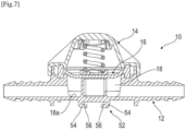
- THE figures 1 to 6 illustrate a first embodiment of a pressure damping device 10 for a fluid circuit, such as fuel.
- the device 10 comprises a lower body 12, an upper cover 14, and a membrane 16 interposed between the body 12 and the cover 14.
- the body 12 is formed in one piece and includes a fluid inlet port 12a and a fluid outlet port 12b.
- the body 12 is for example made by injection molding in plastic material.
- the body 12 further comprises an internal chamber 18 which is connected to the ports 12a, 12b.
- the chamber 18 comprises a bottom 18a at its lower end, its upper end being open.
- the body 12 comprises a middle part of generally circular or cylindrical shape and which has a main axis denoted A (cf. figure 1 And 4 ).
- the ports 12a, 12b extend projecting from this middle part and substantially radially relative to the axis A.
- the ports 12a, 12b are here diametrically opposed to the axis A.
- the ports 12a, 12b are here aligned on an axis B which is perpendicular to axis A.
- Each of the ports 12a, 12b comprises a tubular part forming a male part and configured to be engaged by fitting into a female part such as for example the free end of a pipe.
- Each of the ports 12a, 12b can comprise at its external periphery anchoring ribs 20, in particular in the aforementioned pipe.
- Each of the ports 12a, 12b can be equipped with a seal 22 of the O-ring type for example.
- the chamber 18 has a general circular or cylindrical shape and has an internal diameter D1 ( figure 5 ).
- the chamber 18 is defined by a cylindrical surface 18b of the body 12, onto which internal passages 24 of the ports 12a, 12b open. We see at the figure 1 that the lower ends of these passages 24 are aligned with the bottom 18a of the chamber 18.
- the body 12 comprises at its upper end and around the chamber 18, an annular groove 26.
- the groove 26 is centered on the axis A.
- This groove 26 is delimited at its internal periphery by an annular tooth 28 and at its external periphery by a cylindrical rim 30.
- the tooth 28 is centered on the axis A.
- the tooth 28 extends upwards in a direction parallel to the axis A.
- the tooth 28 extends in the extension of the aforementioned surface 18b.
- Tooth 28 has an internal diameter D1. Furthermore, the tooth 28 here has a height H1 which is measured from the bottom 18a in a direction parallel to the axis A.
- the tooth 28 comprises at its internal periphery an internal peripheral edge 28a which is convex curved and has a radius of curvature greater than 0.1mm and which is for example 0.3mm.
- the rim 30 is centered on the axis A.
- the rim 30 extends upwards in a direction parallel to the axis A.
- the rim 30 has an external diameter D2. Furthermore, the rim 30 here has a height H2 which is measured from the bottom 18a in a direction parallel to the axis A.
- H2 is greater than H1.
- D2 is greater than D1.
- the body 12 further comprises a member 32 for supporting the membrane 16.
- This member 32 projects from the bottom 18a and has a lower end connected to the bottom and a free upper end on which the membrane 16 is able to come to bear. .
- the member 32 has a circular outline and has an external diameter D3 measured relative to the axis A.
- the member 32 has a general tubular shape centered on the axis A.
- the member 32 comprises a tubular wall 32a having a radial thickness E1.
- E1 is preferably less than 2mm, and more preferably less than or equal to 1.5mm.
- the tubular wall 32a here comprises two radial notches 34. We see at the Figure 4 that the notches 34 are diametrically opposed to each other.
- the member 34 has a height H3 measured from the bottom 18a in a direction parallel to the axis A.
- H3 is less than or equal to the height of the chamber 18 defined by the height H1 of the tooth 30.
- H3 would preferably be less than or equal to the maximum height of the bedroom.
- the notches 34 extend over the entire height H3 of the member 32.
- the notches 32 are offset relative to the axis B of the inlet and outlet ports 12a, 12b. In other words, the notches 34 are not exactly aligned with the input and output ports. output 12a, 12b. This is particularly advantageous because it creates pressure losses in the flow of fluid between the inlet and outlet ports 12a, 12b, and thus contributes to the attenuation of pressure peaks.
- the upper end of the member 32 extends in a plane substantially perpendicular to the axis A.
- the cover 14 of the device 10 is visible at figures 1 And 3 . It is fixed on the body 12 above the chamber 18.
- the cover 14 is formed in one piece. It is, for example, made by injection molding in plastic.
- the cover 14 has an internal cavity 36 which is separated from the chamber 18 by the membrane 16.
- the cavity 36 has an internal diameter D4 measured relative to the axis.
- D4 measured relative to the axis.
- the cavity 36 includes a bottom 36a which is oriented towards the bottom 18a of the chamber 18.
- the cover 14 has a general circular or cylindrical shape in the example shown.
- the cavity 36 is defined by a cylindrical surface 36b of the cover 14.
- FIG. 3 shows that the cover 14 comprises at its lower end and around the cavity 36, an annular groove 38.
- the groove 38 is centered on the axis A when the cover 14 is mounted on the body 12.
- This groove 38 is delimited at its internal periphery by an annular tooth 40 and at its external periphery by a cylindrical rim 42.
- the tooth 40 is intended to be centered on the axis A.
- the tooth 40 extends downwards in a direction parallel to the axis A.
- the tooth 40 extends in the extension of the aforementioned surface 36b.
- Tooth 40 has an internal diameter D4. Furthermore, the tooth 40 here has a height H4 which is measured from the bottom 36a in a direction parallel to the axis A.
- the tooth 40 comprises at its internal periphery an internal peripheral edge 40a which is convex curved and has a radius of curvature greater than or equal to 0.5mm and preferably greater than or equal to 0.8mm.
- the rim 42 is centered on the axis A.
- the rim 42 extends downwards in a direction parallel to the axis A.
- the rim 42 has an internal diameter D2. Furthermore, the rim 42 here has a height H5 which is measured from the bottom 36a in a direction parallel to the axis A.
- H5 is greater than H4.
- D1 and D4 are close, identical or similar.
- the cover 14 When mounting the cover 14 on the body 12, the cover 14 is centered on the axis A and the rim 42 of the cover 14 is mounted around the rim 30 of the body 12. These rims 30, 42 are then fixed together for example by welding, and in particular heat welding or laser welding. At the end of the heat sealing, the grooves 26, 38 can be partially or entirely filled with molten material by welding. Laser welding makes it possible to join the edges 30, 42 without filling the grooves 26, 38.
- the membrane 16 is elastically deformable and is preferably made of fluorosilicone and for example FVMQ which is a particularly advantageous material because it allows the membrane 16 to retain its elastic properties over a wide temperature range and in particular at temperatures below 0 °C.
- the temperature range is for example from -40°C to 150°C.
- the membrane 16 is inserted between the body 12 and the cover 14. It has a general circular shape centered on the axis A.
- the membrane 16 comprises a central part 16a which has a constant thickness E2 and a peripheral part 16b which is clamped between the body 12 and the cover 14 to ensure a seal between the chamber 18 and the cavity 36.
- E2 is for example greater than or equal to to 1mm, preferably greater than or equal to 1.5mm, and more preferably greater than or equal to 2mm.
- FIG. 2 shows the membrane 16 in the undeformed and stress-free state.
- its central part 16a is plane or flat.
- the peripheral part 16b of the membrane 16 comprises an annular extra thickness 44, an upper part of which is received in the groove 38 of the cover 14 and a lower part is received in the groove 26 of the body 12.
- the annular extra thickness 44 has an internal diameter D5 and an external diameter D6.
- peripheral part 16b of the membrane 16 comprises lugs 46 projecting radially outwards relative to the axis A. These lugs 46 are distributed around this axis A, preferably regularly, and are advantageously configured to rest on the rim 30 of the body 12 so as to center the membrane 16 on the axis A.
- the central part 16a of the membrane 16 comprises a first part 16a1 in the center and a second part 16a2 around the first part 16a.
- the first part 16a has an external diameter D7 and the second part has an external diameter D8.
- the central part 16a comprises two opposite and parallel circular faces, upper and lower respectively.
- the tightening teeth 28, 40 are configured to tighten and pinch together the junction between the central part 16a and the peripheral part 16b of the membrane 16.
- the tightening extends in the radial direction from the internal diameters D1, D4 teeth 28, 40 up to the external diameters of these teeth 28, 40 or up to the internal diameter D5 of the extra thickness 44.
- the device 10 further comprises a spring 48 and a cup 50 which are housed in the cavity 36.
- Spring 48 is centered on axis A and is here a helical spring.
- the spring 48 has an upper end 48a which rests on the bottom 36a of the cavity 36 and which can be centered on this bottom 36a by cooperation of shapes with a complementary portion of this bottom 36a.
- the spring 48 further comprises a lower end 48b which bears on the cup 50 which is interposed between the spring 48 and the upper face of the membrane 16.
- the cup 50 is centered on the axis A and can also include a complementary portion of the lower end 48b of the spring 48 to center it on the axis A.
- the spring 48 has an external diameter D9 and the cup 50 has an external diameter D10.
- D9 Preferably, 0.8.D9 ⁇ D10 ⁇ 1.2.D9 and/or 0.8.D3 ⁇ D9 ⁇ 1.2.D3 and/or 0.8.D3 ⁇ D10 ⁇ 1.2.D3.
- the membrane 16 is stressed and deformed by the spring 48 so that its first part 16a1 is flat and rests on the upper end of the member 32, and its second part 16a2 is frustoconical.
- the second part 16a2 flares from bottom to top.
- D1 is greater than 1.5.D3, preferably D1 is greater than 1.8.D3, more preferably D1 is greater than 2.D3.
- D1 is equal to 2.2.D3. This allows the membrane 16 to have a good capacity for elastic deformation because a large part of it is free to deform elastically without being supported on a part or stressed by a part.
- FIG. 6 shows the device 10 of the figure 1 in use.
- the arrows show the circulation of the fluid and for example fuel from the entry port 12a to the exit port 12b.
- a certain threshold which is a function of the deformation capacity of the membrane 16 and the stiffness of the spring 48
- the spring 48 is compressed and the membrane 16 is deformed by moving away from the member 32.
- the membrane 16 remains constrained by the spring 48 and resting on the support member 32.
- a pressure peak appears in the device 10
- the membrane 16 is stressed by the fluid and deforms.
- the truncated conicality of the membrane 16 and in particular of its second part 16a2 can then be reversed.
- the compression of the spring 48 and the deformation of the membrane 16 then dampen the peak pressure of the fluid beyond the aforementioned threshold.
- THE figures 7 And 8 illustrate a variant embodiment of the device 10 according to the invention which differs from that described in the above essentially in that its body 12 comprises a slide system 52.
- this slide system 52 is located under the body 12, just below the bottom 18a of the chamber 18.
- This slide system 52 comprises for example two parallel lateral hooks 54 which have a general L shape or C and which define openings 56 facing each other.
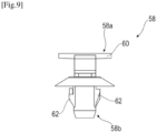
- the device 10 further comprises a connecting element 58 represented alone at the Figure 9 .
- This connecting element 58 is formed in one piece and comprises two fixing parts 58a, 58b.
- the first fixing part 58a is configured to cooperate by sliding with the system to slide 52 and comprises for example a rail 60 configured to be engaged between the hooks 54 and in particular in their openings 56.
- the second fixing part 58b comprises one or more elastic latching tabs 62.
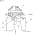
- FIG 8 shows the device 10 of the Figure 7 fixed on a support plate 64 by means of the connecting element 58 of the Figure 9 .
- the plate 64 has a general inverted U or ⁇ shape and comprises an upper wall 64a provided with an orifice 66 in which the second fixing part 58b of the connecting element 58 is engaged.
- the tabs 62 cooperate by elastic snap-fastening with the edges of this orifice 66 and ensure the retention of the connecting element 58 in the orifice 66.
- the rail 60 of the connecting element 58 can be engaged by sliding in the hooks 54 of the slide system 52.
- the device 10 is then held fixedly on the plate 64 and can be detached from it if necessary by manual actuation of the tabs 62 and removal of the connecting element 58 from the plate 64, or extraction of the rail 60 from the hooks 54 of the device 10.
- the device 10 can thus be mounted in environments presenting strong integration constraints.
Abstract
Dispositif (10) d'amortissement de pression pour un circuit de fluide, ce dispositif comportant :- un corps (12) inférieur comportant des ports (12a, 12b) d'entrée et de sortie de fluide,- un couvercle (14) supérieur fixé sur le corps (12),- une membrane (16) élastiquement déformable intercalée entre le corps (12) et le couvercle (14),- une coupelle (50) circulaire disposée sur la membrane (16), et- un ressort (48) intercalé entre la coupelle (50) et un fond (36a) du couvercledans lequel le corps (12) comprend un organe (32) de support de la membrane (16), cet organe de support (32) étant en saillie sur le premier fond (18a) et comportant une extrémité supérieure libre sur laquelle la membrane (16) est apte à venir en appui.Pressure damping device (10) for a fluid circuit, this device comprising: - a lower body (12) comprising fluid inlet and outlet ports (12a, 12b), - an upper cover (14) fixed on the body (12), - an elastically deformable membrane (16) interposed between the body (12) and the cover (14), - a circular cup (50) placed on the membrane (16), and - a spring ( 48) interposed between the cup (50) and a bottom (36a) of the cover in which the body (12) comprises a member (32) for supporting the membrane (16), this support member (32) being projecting on the first bottom (18a) and comprising a free upper end on which the membrane (16) is able to come to bear.
Description
La présente invention concerne un dispositif d'amortissement de pression pour un circuit de fluide, et en particulier pour un circuit de carburant pour un véhicule.The present invention relates to a pressure damping device for a fluid circuit, and in particular for a fuel circuit for a vehicle.
L'arrière-plan technique comprend notamment les documents
Un dispositif d'amortissement de pression pour un circuit de fluide, et en particulier de carburant, est un dispositif qui permet d'amortir les variations de pression d'un fluide dans un circuit. Dans le cas d'un circuit de carburant pour véhicule automobile, ce type de dispositif permet d'atténuer les pics de pression du carburant qui sont susceptibles de générer des nuisances vibratoires et acoustiques dans l'habitacle du véhicule.A pressure damping device for a fluid circuit, and in particular a fuel circuit, is a device which makes it possible to dampen pressure variations of a fluid in a circuit. In the case of a fuel circuit for a motor vehicle, this type of device makes it possible to attenuate fuel pressure peaks which are likely to generate vibration and acoustic nuisances in the passenger compartment of the vehicle.
Le document
- un corps inférieur comportant des ports d'entrée et de sortie de carburant qui sont raccordés à une chambre située entre les ports d'entrée et de sortie,
- un couvercle supérieur fixé sur le corps au-dessus de la chambre, ce couvercle comportant une cavité interne, et
- une membrane élastiquement déformable intercalée entre le corps et le couvercle, la membrane ayant une partie périphérique serrée entre le corps et le couvercle pour assurer une étanchéité entre la chambre et la cavité.
- a lower body having fuel inlet and outlet ports which are connected to a chamber located between the inlet and outlet ports,
- an upper cover fixed to the body above the chamber, this cover comprising an internal cavity, and
- an elastically deformable membrane interposed between the body and the cover, the membrane having a peripheral part clamped between the body and the cover to ensure a seal between the chamber and the cavity.
La capacité de déformation élastique de la membrane permet d'atténuer les pics de pression du carburant qui circulent dans la chambre depuis le port d'entrée jusqu'au port de sortie.The elastic deformation capacity of the membrane helps to attenuate fuel pressure peaks flowing through the chamber from the inlet port to the outlet port.
Dans ce dispositif, l'amortissement de la pression est uniquement obtenu par cette capacité de déformation. Ce dispositif peut être utilisé pour un circuit de carburant basse pression (typiquement inférieure à 2 bars) voire haute pression (typiquement supérieure ou égale à 2 bars).In this device, pressure damping is only obtained by this deformation capacity. This device can be used for a low pressure fuel circuit (typically less than 2 bars) or even high pressure (typically greater than or equal to 2 bars).
Lorsqu'un dispositif d'amortissement est destiné à équiper un circuit haute pression, il comprend en général en plus un ressort qui est logé dans la cavité du couvercle et qui prend appui sur la membrane par l'intermédiaire d'une coupelle.When a damping device is intended to equip a high pressure circuit, it generally also includes a spring which is housed in the cavity of the cover and which is supported on the membrane via a cup.
Dans cette configuration, la raideur du ressort et la capacité de déformation de la membrane participent ensemble à l'amortissement de la pression, ce qui permet l'utilisation du dispositif dans des circuits haute pression.In this configuration, the stiffness of the spring and the deformation capacity of the membrane contribute together to damping the pressure, which allows the use of the device in high pressure circuits.
La présente invention propose un perfectionnement à la technique actuelle, qui permet notamment d'améliorer l'efficacité d'amortissement du dispositif tout en limitant son encombrement.The present invention proposes an improvement to the current technique, which makes it possible in particular to improve the damping efficiency of the device while limiting its bulk.
L'invention concerne un dispositif d'amortissement de pression pour un circuit de fluide, ce dispositif comportant :
- un corps inférieur comportant des ports d'entrée et de sortie de fluide qui sont raccordés à une chambre située entre les ports d'entrée et de sortie, le corps étant formé d'une seule pièce et la chambre comportant un premier fond,
- un couvercle supérieur fixé sur le corps au-dessus de la chambre, ce couvercle comportant une cavité interne présentant un second fond orienté vers le premier fond de la chambre,
- une membrane élastiquement déformable intercalée entre le corps et le couvercle, la membrane ayant une forme générale circulaire et comportant une partie centrale qui a une épaisseur constante et une partie périphérique qui est serrée entre le corps et le couvercle pour assurer une étanchéité entre la chambre et la cavité,
- une coupelle circulaire disposée dans la cavité et sur la partie centrale de la membrane, et
- un ressort intercalé entre la coupelle et le second fond de la cavité,
- l'organe s'étend depuis le premier fond le long d'un axe central sur une hauteur qui est inférieure ou égale à une hauteur de la chambre, cet organe ayant un contour circulaire et ayant un diamètre externe D3 mesuré par rapport audit axe,
- la coupelle est centrée sur ledit axe et a un diamètre externe D10 mesuré par rapport audit axe, avec 0,8.D3 < D10 < 1,2.D3, et
- la membrane est centrée sur ledit axe et sa partie périphérique a un diamètre interne de serrage D1 mesuré par rapport audit axe, avec D1 > 1,5.D3.
- a lower body comprising fluid inlet and outlet ports which are connected to a chamber located between the inlet and outlet ports, the body being formed in one piece and the chamber comprising a first bottom,
- an upper cover fixed to the body above the chamber, this cover comprising an internal cavity having a second bottom oriented towards the first bottom of the chamber,
- an elastically deformable membrane interposed between the body and the cover, the membrane having a generally circular shape and comprising a central part which has a constant thickness and a peripheral part which is clamped between the body and the cover to ensure a seal between the chamber and the cavity,
- a circular cup placed in the cavity and on the central part of the membrane, and
- a spring inserted between the cup and the second bottom of the cavity,
- the member extends from the first bottom along a central axis over a height which is less than or equal to a height of the chamber, this member having a circular outline and having an external diameter D3 measured relative to said axis,
- the cup is centered on said axis and has an external diameter D10 measured relative to said axis, with 0.8.D3 < D10 < 1.2.D3, and
- the membrane is centered on said axis and its peripheral part has an internal clamping diameter D1 measured relative to said axis, with D1 > 1.5.D3.
Une des particularités du dispositif selon l'invention concerne son corps qui est formé d'une seule pièce avec un organe de support de la membrane. La hauteur de cet organe est déterminée pour que la membrane adopte une forme particulière à l'état déformé lorsqu'elle prend appui sur l'extrémité supérieure de cet organe. La membrane est en appui par sa face inférieure sur l'organe et la coupelle prend appui sur la face supérieure de la membrane. La forme de l'organe est en outre déterminée pour être simple et peu encombrante, ce qui facilite la fabrication du corps et donc du dispositif et limite l'impact sur l'encombrement global du dispositif.One of the particularities of the device according to the invention concerns its body which is formed in one piece with a membrane support member. The height of this organ is determined so that the membrane adopts a particular shape in the deformed state when it rests on the upper end of this organ. The membrane rests on its lower face on the organ and the cup rests on the upper face of the membrane. The shape of the member is also determined to be simple and compact, which facilitates the manufacture of the body and therefore of the device and limits the impact on the overall size of the device.
Une autre des particularités de l'invention concerne le ratio entre les dimensions transversales de l'organe et de la coupelle, d'une part, et de la dimension transversale de la membrane, et en particulier de sa partie centrale, d'autre part. Ce ratio est déterminé pour qu'une partie significative de la membrane ne soit pas en appui sur l'organe ou la coupelle en fonctionnement et puisse librement se déformer élastiquement en fonctionnement, ce qui permet d'optimiser l'amortissement des pics de pression. En effet, plus la zone déformable de la membrane est grande et plus l'amortissement en pression peut être grand.Another of the particularities of the invention concerns the ratio between the transverse dimensions of the organ and the cup, on the one hand, and the transverse dimension of the membrane, and in particular of its part central, on the other hand. This ratio is determined so that a significant part of the membrane does not rest on the member or the cup in operation and can freely deform elastically in operation, which makes it possible to optimize the damping of pressure peaks. In fact, the larger the deformable zone of the membrane, the greater the pressure damping can be.
Lorsqu'un fluide à basse ou haute pression circule dans le dispositif, une pression est exercée sur la membrane qui va se déformer. La déformation de cette membrane est limitée par le ressort. Le ressort se comprime en fonction de la pression appliquée sur la membrane. L'effet de la déformation de la membrane et du ressort permet une régulation constante et autonome des variations de pression au sein du circuit par augmentation ponctuelle du volume fluide, ce qui implique par conséquent une réduction du bruit présent dans le circuit.When a low or high pressure fluid circulates in the device, pressure is exerted on the membrane which will deform. The deformation of this membrane is limited by the spring. The spring compresses according to the pressure applied to the membrane. The effect of the deformation of the membrane and the spring allows constant and autonomous regulation of pressure variations within the circuit by occasional increase in the fluid volume, which consequently implies a reduction in the noise present in the circuit.
Le dispositif selon l'invention a l'avantage d'être compact et autonome et de pouvoir fonctionner à basse température et haute pression.The device according to the invention has the advantage of being compact and autonomous and of being able to operate at low temperature and high pressure.
Le dispositif selon l'invention peut comprendre une ou plusieurs des caractéristiques suivantes, prises isolément les unes des autres, ou en combinaison les unes avec les autres :
- l'organe a une forme générale tubulaire centrée sur ledit axe ;
- l'organe comprend une paroi tubulaire centrée sur ledit axe et ayant une épaisseur radiale inférieure ou égale à l'épaisseur de la partie centrale de la membrane ;
- la paroi tubulaire comprend au moins deux encoches radiales ;
- les encoches sont diamétralement opposées et/ou s'étendent sur toute la hauteur de l'organe ;
- les ports d'entrée et de sortie sont diamétralement opposés par rapport audit axe et alignés sur un autre axe, lesdites encoches étant décalées par rapport à cet autre axe ;
- la membrane est contrainte et déformée par le ressort de façon à comprendre une première partie au centre qui est plane et en appui sur ledit organe, et une seconde partie autour de la première partie qui est tronconique ;
- la cavité a un diamètre interne D4 mesuré par rapport à l'axe, et la chambre a un diamètre interne D3 mesuré par rapport à l'axe, avec 0,8.D3 < D4 < 1 ,2.D3 ;
- le couvercle comprend une première dent annulaire de serrage de la membrane, cette première dent comportant un bord périphérique intérieur situé du côté dudit axe, qui est arrondi et présente un rayon de courbure supérieur à 0,5mm, de préférence supérieur ou égal à 0,8mm, et par exemple compris entre 0,8mm et 1mm, et/ou le corps comprend une seconde dent annulaire de serrage de la membrane, cette seconde dent comportant un bord périphérique intérieur situé du côté dudit axe, qui est arrondi et présente un rayon de courbure supérieur à 0,1mm, de préférence supérieur ou égal à 0,2mm, et par exemple compris entre 0,2mm et 0,4mm ;
- la partie périphérique de la membrane comprend une surépaisseur annulaire dont une partie supérieure est reçue dans une gorge annulaire du couvercle et une partie inférieure est reçue dans une gorge annulaire du corps ;
- la partie périphérique de la membrane comprend des ergots en saillie radialement vers l'extérieur par rapport audit axe, ces ergots étant répartis autour de cet axe ;
- la partie centrale de la membrane est plane à l'état sans contrainte (c'est-à-dire sans sollicitation par le ressort ou par le fluide) ;
- la partie centrale de la membrane a une épaisseur supérieure ou égale à 1mm, de préférence supérieure ou égale à 1 ,5mm, et plus préférentiellement supérieure ou égale à 2mm ;
- -- la membrane est réalisée en FVMQ ;
- le corps comprend un système à glissière, le dispositif comportant en outre un élément de liaison qui est formé d'une seule pièce et comprend deux parties de fixation, la première partie de fixation étant configurée pour coopérer par coulissement avec le système à glissière du corps, et la seconde partie de fixation comportant au moins un patte d'encliquetage élastique ;
- --D1 > 2.D3 ;
- -- ladite hauteur de la chambre est la hauteur maximale de la chambre ;
- -- l'épaisseur de l'organe est inférieure à 2mm, et de préférence inférieure ou égale à 1,5mm ;
- -- D3 est comprise entre 5 et 30mm, et de préférence entre 10 et 20mm, et plus préférentiellement entre 10 et 15mm ;
- -- D1 est comprise
entre 10 et 60mm, de préférence entre 20 et 40mm, et plus préférentiellement entre 20 et 30mm ; - -- D10 est comprise entre 5 et 30mm, de préférence entre 10 et 20mm, et plus préférentiellement entre 10 et 15mm ;
- -- le couvercle est fixé au corps par soudage (c'est-à-dire par un cordon de soudure), et par exemple par thermosoudage ou soudage laser.
- the organ has a general tubular shape centered on said axis;
- the member comprises a tubular wall centered on said axis and having a radial thickness less than or equal to the thickness of the central part of the membrane;
- the tubular wall comprises at least two radial notches;
- the notches are diametrically opposite and/or extend over the entire height of the organ;
- the input and output ports are diametrically opposed with respect to said axis and aligned with another axis, said notches being offset with respect to this other axis;
- the membrane is stressed and deformed by the spring so as to comprise a first part in the center which is flat and rests on said member, and a second part around the first part which is frustoconical;
- the cavity has an internal diameter D4 measured relative to the axis, and the chamber has an internal diameter D3 measured relative to the axis, with 0.8.D3 < D4 <1.2.D3;
- the cover comprises a first annular tooth for tightening the membrane, this first tooth comprising an interior peripheral edge located on the side of said axis, which is rounded and has a radius of curvature greater than 0.5 mm, preferably greater than or equal to 0, 8mm, and for example between 0.8mm and 1mm, and/or the body comprises a second annular tooth for tightening the membrane, this second tooth comprising an inner peripheral edge located on the side of said axis, which is rounded and has a radius of curvature greater than 0.1mm, preferably greater than or equal to 0.2mm, and for example between 0.2mm and 0.4mm;
- the peripheral part of the membrane comprises an annular extra thickness, an upper part of which is received in an annular groove of the cover and a lower part is received in an annular groove of the body;
- the peripheral part of the membrane comprises lugs projecting radially outwards relative to said axis, these lugs being distributed around this axis;
- the central part of the membrane is flat in the stress-free state (that is to say without stress by the spring or by the fluid);
- the central part of the membrane has a thickness greater than or equal to 1mm, preferably greater than or equal to 1.5mm, and more preferably greater than or equal to 2mm;
- -- the membrane is made of FVMQ;
- the body comprises a slide system, the device further comprising a connecting element which is formed in one piece and comprises two fixing parts, the first fixing part being configured to cooperate by sliding with the slide system of the body , and the second fixing part comprising at least one elastic snap tab;
- --D1 >2.D3;
- -- said height of the chamber is the maximum height of the chamber;
- -- the thickness of the organ is less than 2mm, and preferably less than or equal to 1.5mm;
- -- D3 is between 5 and 30mm, and preferably between 10 and 20mm, and more preferably between 10 and 15mm;
- -- D1 is between 10 and 60mm, preferably between 20 and 40mm, and more preferably between 20 and 30mm;
- -- D10 is between 5 and 30mm, preferably between 10 and 20mm, and more preferably between 10 and 15mm;
- -- the cover is fixed to the body by welding (that is to say by a weld bead), and for example by heat welding or laser welding.
La présente invention concerne également un circuit de carburant pour un véhicule, en particulier automobile, comportant au moins un dispositif tel que décrit ci-dessus.The present invention also relates to a fuel circuit for a vehicle, in particular an automobile, comprising at least one device as described above.
D'autres caractéristiques et avantages ressortiront de la description qui suit d'un mode de réalisation non limitatif de l'invention en référence aux dessins annexés sur lesquels :
- [
Fig. 1 ] lafigure 1 est une vue schématique en coupe axiale d'un dispositif d'amortissement de pression selon l'invention, et illustre ce dispositif à l'état non fonctionnel ; - [
Fig. 2 ] lafigure 2 est une vue schématique en perspective d'une membrane du dispositif de lafigure 1 ; - [
Fig. 3 ] lafigure 3 est une vue schématique en perspective d'un couvercle du dispositif de lafigure 1 ; - [
Fig. 4 ] lafigure 4 est une vue schématique en perspective d'un corps du dispositif de lafigure 1 ; - [
Fig. 5 ] lafigure 5 est une vue schématique illustrant une partie du corps de lafigure 4 ; - [
Fig. 6 ] lafigure 6 est une vue similaire à celle de lafigure 1 et illustre le dispositif en cours d'amortissement ; - [
Fig. 7 ] lafigure 7 est une vue similaire à celle de lafigure 1 et illustre une variante de réalisation du dispositif ; - [
Fig. 8 ] lafigure 8 est une vue schématique en perspective du dispositif de lafigure 7 et d'une platine de support de ce dispositif ; et - [
Fig. 9 ] lafigure 9 est une vue schématique en perspective d'un élément de liaison du dispositif de lafigure 7 à la platine de support de lafigure 8 .
- [
Fig. 1 ] therefigure 1 is a schematic view in axial section of a pressure damping device according to the invention, and illustrates this device in the non-functional state; - [
Fig. 2 ] therefigure 2 is a schematic perspective view of a membrane of the device of thefigure 1 ; - [
Fig. 3 ] thereFigure 3 is a schematic perspective view of a cover of the device of thefigure 1 ; - [
Fig. 4 ] thereFigure 4 is a schematic perspective view of a body of the device of thefigure 1 ; - [
Fig. 5 ] therefigure 5 is a schematic view illustrating part of the body of thefigure 4 ; - [
Fig. 6 ] thereFigure 6 is a view similar to that of thefigure 1 and illustrates the device being amortized; - [
Fig. 7 ] thereFigure 7 is a view similar to that of thefigure 1 and illustrates a variant embodiment of the device; - [
Fig. 8 ] therefigure 8 is a schematic perspective view of the device of theFigure 7 and a support plate for this device; And - [
Fig. 9 ] thereFigure 9 is a schematic perspective view of a connecting element of the device of theFigure 7 to the support plate of thefigure 8 .
Les
Le corps 12 est formé d'une seule pièce et comprend un port 12a d'entrée de fluide et un port 12b de sortie de fluide. Le corps 12 est par exemple réalisé par injection-moulage en matière plastique.The
Le corps 12 comprend en outre une chambre interne 18 qui est raccordée aux ports 12a, 12b. La chambre 18 comprend un fond 18a à son extrémité inférieure, son extrémité supérieure étant ouverte.The
Dans l'exemple représenté, le corps 12 comprend une partie médiane de forme générale circulaire ou cylindrique et qui présente un axe principal noté A (cf.
Chacun des ports 12a, 12b comprend une partie tubulaire formant une partie mâle et configurée pour être engagée par emmanchement dans une partie femelle telle que par exemple l'extrémité libre d'un tuyau. Chacun des ports 12a, 12b peut comprendre à sa périphérie externe des nervures d'ancrage 20, en particulier dans le tuyau précité. Chacun des ports 12a, 12b peut être équipé d'un joint d'étanchéité 22 du type torique par exemple.Each of the
La chambre 18 a une forme générale circulaire ou cylindrique et a un diamètre interne D1 (
La
La dent 28 est centrée sur l'axe A. La dent 28 s'étend vers le haut dans une direction parallèle à l'axe A. La dent 28 s'étend dans le prolongement de la surface 18b précitée.The
La dent 28 a un diamètre interne D1. Par ailleurs, la dent 28 présente ici une hauteur H1 qui est mesurée depuis le fond 18a dans une direction parallèle à l'axe A.
Avantageusement, la dent 28 comprend à sa périphérie interne un bord périphérique interne 28a qui est incurvée convexe et présente un rayon de courbure supérieur à 0,1mm et qui est par exemple de 0,3mm.Advantageously, the
Le rebord 30 est centré sur l'axe A. Le rebord 30 s'étend vers le haut dans une direction parallèle à l'axe A.The
Le rebord 30 a un diamètre externe D2. Par ailleurs, le rebord 30 présente ici une hauteur H2 qui est mesurée depuis le fond 18a dans une direction parallèle à l'axe A.The
Dans l'exemple représenté, H2 est supérieure à H1. Par ailleurs, D2 est supérieur à D1.In the example shown, H2 is greater than H1. Furthermore, D2 is greater than D1.
Le corps 12 comprend en outre un organe 32 de support de la membrane 16. Cet organe 32 est en saillie sur le fond 18a et comporte une extrémité inférieure reliée au fond et une extrémité supérieure libre sur laquelle la membrane 16 est apte à venir en appui.The
L'organe 32 a un contour circulaire et a un diamètre externe D3 mesuré par rapport à l'axe A.The
Avantageusement, comme dans l'exemple représenté, l'organe 32 a une forme générale tubulaire centrée sur l'axe A. L'organe 32 comprend une paroi tubulaire 32a ayant une épaisseur radiale E1.Advantageously, as in the example shown, the
E1 est de préférence inférieure à 2mm, et plus préférentiellement inférieure ou égale à 1,5mm.E1 is preferably less than 2mm, and more preferably less than or equal to 1.5mm.
La paroi tubulaire 32a comprend ici deux encoches radiales 34. On constate à la
L'organe 34 a une hauteur H3 mesurée depuis le fond 18a dans une direction parallèle à l'axe A. Dans la
On constate également aux
Le couvercle 14 du dispositif 10 est visible aux
Le couvercle 14 est formé d'une seule pièce. Il est par exemple réalisé par injection-moulage en matière plastique.The
Le couvercle 14 comporte une cavité interne 36 qui est séparée de la chambre 18 par la membrane 16.The
La cavité 36 a un diamètre interne D4 mesuré par rapport à l'axe. De préférence : 0,8.D1 < D4 < 1,2.D1.The
La cavité 36 comprend un fond 36a qui est orienté vers le fond 18a de la chambre 18.The
Le couvercle 14 a une forme générale circulaire ou cylindrique dans l'exemple représenté. La cavité 36 est définie par une surface cylindrique 36b du couvercle 14.The
La
La dent 40 est destinée à être centrée sur l'axe A. La dent 40 s'étend vers le bas dans une direction parallèle à l'axe A. La dent 40 s'étend dans le prolongement de la surface 36b précitée.The
La dent 40 a un diamètre interne D4. Par ailleurs, la dent 40 présente ici une hauteur H4 qui est mesurée depuis le fond 36a dans une direction parallèle à l'axe A.
Avantageusement, la dent 40 comprend à sa périphérie interne un bord périphérique interne 40a qui est incurvé convexe et présente un rayon de courbure supérieur ou égal à 0,5mm et de préférence supérieur ou égal à 0,8mm.Advantageously, the
Le rebord 42 est centré sur l'axe A. Le rebord 42 s'étend vers le bas dans une direction parallèle à l'axe A.The
Le rebord 42 a un diamètre interne D2. Par ailleurs, le rebord 42 présente ici une hauteur H5 qui est mesurée depuis le fond 36a dans une direction parallèle à l'axe A.The
Dans l'exemple représenté, H5 est supérieure à H4.In the example shown, H5 is greater than H4.
Avantageusement, D1 et D4 sont proches, identiques ou similaires.Advantageously, D1 and D4 are close, identical or similar.
Lors du montage du couvercle 14 sur le corps 12, le couvercle 14 est centré sur l'axe A et le rebord 42 du couvercle 14 est monté autour du rebord 30 du corps 12. Ces rebords 30, 42 sont alors fixés ensemble par exemple par soudage, et en particulier thermosoudage ou soudage laser. A l'issue du thermosoudage, les gorges 26, 38 peuvent être partiellement ou entièrement comblées par de la matière fondue par soudage. Le soudage laser permet de solidariser les rebords 30, 42 sans comblement des gorges 26, 38.When mounting the
La membrane 16 est élastiquement déformable et est de préférence réalisée en fluorosilicone et par exemple FVMQ qui est un matériau particulièrement avantageux car il permet à la membrane 16 de conserver ses propriétés élastiques sur une grande plage de température et en particulier à des températures inférieures à 0°C. La plate de température est par exemple de -40°C à 150°C.The
La membrane 16 est intercalée entre le corps 12 et le couvercle 14. Elle a une forme générale circulaire centrée sur l'axe A.The
La membrane 16 comporte une partie centrale 16a qui a une épaisseur constante E2 et une partie périphérique 16b qui est serrée entre le corps 12 et le couvercle 14 pour assurer une étanchéité entre la chambre 18 et la cavité 36. E2 est par exemple supérieure ou égale à 1mm, de préférence supérieure ou égale à 1,5mm, et plus préférentiellement supérieure ou égale à 2mm.The
La
La surépaisseur annulaire 44 a un diamètre interne D5 et un diamètre externe D6.The annular
De plus, la partie périphérique 16b de la membrane 16 comprend des ergots 46 en saillie radialement vers l'extérieur par rapport à l'axe A. Ces ergots 46 sont répartis autour de cet axe A, de préférence régulièrement, et sont avantageusement configurés pour prendre appui sur le rebord 30 du corps 12 de façon à centrer la membrane 16 sur l'axe A.In addition, the
La partie centrale 16a de la membrane 16 comprend une première partie 16a1 au centre et une seconde partie 16a2 autour de la première partie 16a. La première partie 16a a un diamètre externe D7 et la seconde partie a un diamètre externe D8.The
Par ailleurs, la partie centrale 16a comprend deux faces circulaires opposées et parallèles, respectivement supérieure et inférieure.Furthermore, the
En considérant les
Le dispositif 10 comprend en outre un ressort 48 et une coupelle 50 qui sont logés dans la cavité 36.The
Le ressort 48 est centré sur l'axe A et est ici un ressort hélicoïdal. Le ressort 48 a une extrémité supérieure 48a qui prend appui sur le fond 36a de la cavité 36 et qui peut être centrée sur ce fond 36a par coopération de formes avec une portion complémentaire de ce fond 36a. Le ressort 48 comprend en outre une extrémité inférieure 48b qui prend appui sur la coupelle 50 qui est intercalée entre le ressort 48 et la face supérieure de la membrane 16. La coupelle 50 est centrée sur l'axe A et peut également comprendre une portion complémentaire de l'extrémité inférieure 48b du ressort 48 pour la centrer sur l'axe A.
Le ressort 48 a un diamètre externe D9 et la coupelle 50 a un diamètre externe D10. De préférence, 0,8.D9 < D10 < 1,2.D9 et/ou 0,8.D3 < D9 < 1,2.D3 et/ou 0,8.D3 < D10 < 1,2.D3.The
On constate à la
Selon l'invention, D1 est supérieur à 1,5.D3, de préférence D1 est supérieur 1,8.D3, plus préférentiellement D1 est supérieur à 2.D3. Par exemple, D1 est égal à 2,2.D3. Ceci permet à la membrane 16 d'avoir une bonne capacité de déformation élastique car une grande partie de celle-ci est libre de se déformer élastiquement sans être en appui sur une pièce ou sollicitée par une pièce.According to the invention, D1 is greater than 1.5.D3, preferably D1 is greater than 1.8.D3, more preferably D1 is greater than 2.D3. For example, D1 is equal to 2.2.D3. This allows the
La
Les
Dans l'exemple représenté, ce système à glissière 52 est situé sous le corps 12, juste au-dessous du fond 18a de la chambre 18. Ce système à glissière 52 comprend par exemple deux crochets latéraux 54 parallèles qui ont une forme générale en L ou C et qui définissent des ouvertures 56 en regard l'une de l'autre.In the example shown, this
Le dispositif 10 comporte en outre un élément de liaison 58 représenté seul à la
La seconde partie de fixation 58b comporte une ou plusieurs pattes 62 d'encliquetage élastique.The
La
Le dispositif 10 peut ainsi être monté dans des environnements présentant de fortes contraintes d'intégration.The
Claims (15)
et dans lequel :
and in which:
Applications Claiming Priority (1)
| Application Number | Priority Date | Filing Date | Title |
|---|---|---|---|
| FR2202642A FR3133899B1 (en) | 2022-03-24 | 2022-03-24 | PRESSURE DAMPING DEVICE FOR A FLUID CIRCUIT |
Publications (1)
| Publication Number | Publication Date |
|---|---|
| EP4249787A1 true EP4249787A1 (en) | 2023-09-27 |
Family
ID=81851004
Family Applications (1)
| Application Number | Title | Priority Date | Filing Date |
|---|---|---|---|
| EP23162782.9A Pending EP4249787A1 (en) | 2022-03-24 | 2023-03-20 | Pressure damping device for a fluid circuit |
Country Status (4)
| Country | Link |
|---|---|
| US (1) | US20230323844A1 (en) |
| EP (1) | EP4249787A1 (en) |
| CN (1) | CN219993813U (en) |
| FR (1) | FR3133899B1 (en) |
Citations (4)
| Publication number | Priority date | Publication date | Assignee | Title |
|---|---|---|---|---|
| FR2721354A1 (en) | 1994-06-21 | 1995-12-22 | Walbro Corp | Accumulator and automobile fuel distribution circuit. |
| WO2011097124A1 (en) | 2010-02-02 | 2011-08-11 | Continental Automotive Systems, Inc. | Comprehensive fuel pressure damper |
| FR3012849A1 (en) | 2013-11-04 | 2015-05-08 | Nobel Plastiques | DAMPING DEVICE FOR PULSATIONS. |
| EP3532722A1 (en) | 2016-10-26 | 2019-09-04 | Hutchinson, Srl | Damper for a fluid line, in particular a fuel line for an internal combustion engine |
-
2022
- 2022-03-24 FR FR2202642A patent/FR3133899B1/en active Active
-
2023
- 2023-03-14 CN CN202320501622.7U patent/CN219993813U/en active Active
- 2023-03-17 US US18/185,887 patent/US20230323844A1/en active Pending
- 2023-03-20 EP EP23162782.9A patent/EP4249787A1/en active Pending
Patent Citations (4)
| Publication number | Priority date | Publication date | Assignee | Title |
|---|---|---|---|---|
| FR2721354A1 (en) | 1994-06-21 | 1995-12-22 | Walbro Corp | Accumulator and automobile fuel distribution circuit. |
| WO2011097124A1 (en) | 2010-02-02 | 2011-08-11 | Continental Automotive Systems, Inc. | Comprehensive fuel pressure damper |
| FR3012849A1 (en) | 2013-11-04 | 2015-05-08 | Nobel Plastiques | DAMPING DEVICE FOR PULSATIONS. |
| EP3532722A1 (en) | 2016-10-26 | 2019-09-04 | Hutchinson, Srl | Damper for a fluid line, in particular a fuel line for an internal combustion engine |
Also Published As
| Publication number | Publication date |
|---|---|
| CN219993813U (en) | 2023-11-10 |
| FR3133899A1 (en) | 2023-09-29 |
| FR3133899B1 (en) | 2024-02-16 |
| US20230323844A1 (en) | 2023-10-12 |
Similar Documents
| Publication | Publication Date | Title |
|---|---|---|
| FR2860278A1 (en) | FIXING FLANGE FOR FLUID TRANSPORT PIPE | |
| EP0304349B1 (en) | Hydraulic elastic joint, particularly used for mounting an internal combustion engine in a motor vehicle | |
| EP2717987B1 (en) | Liquid filter and engine subassembly acting as a support on which to mount a filter canister | |
| FR2740526A1 (en) | COMPOSITE SEAL FOR A SEALED CONNECTION BETWEEN A TUBE END AND A PART, AND A PIECE / TUBE ASSEMBLY COMPRISING SUCH A SEAL | |
| FR2461838A1 (en) | FIXING DEVICE FOR ELECTRIC FUEL PUMPS | |
| EP1254692B1 (en) | Fluid filter for an automotive internal combustion engine | |
| FR2978061A1 (en) | FUEL FILTER WITH LOWER WATER COLLECTION COMPARTMENT AND FILTER ELEMENT FOR SUCH A FILTER | |
| EP4249787A1 (en) | Pressure damping device for a fluid circuit | |
| FR3043732B1 (en) | FUEL RAMP WITH PULSATION DAMPING | |
| FR2863944A1 (en) | Strut for motor vehicle, has spring up with support for suspension spring of vehicle, where support is extended radially up to axial front surface of stop and is fixed to spring up by interlocking connection | |
| FR2741913A1 (en) | SPHERE, IN PARTICULAR PNEUMATIC, FOR EXAMPLE FOR HYDROPNEUMATIC SUSPENSION OF A MOTOR VEHICLE | |
| FR2741920A1 (en) | IMPROVED DEVICE FOR HYDRAULICALLY CONTROLLING A CLUTCH OF A MOTOR VEHICLE | |
| CH665896A5 (en) | PHONE DAMPING DEVICE FOR SANITARY INSTALLATION PIPE. | |
| FR3136441A1 (en) | Method of attaching a cover to an orifice of a power steering system and such a cover | |
| EP0957286B1 (en) | Hydroelastic support for the suspension of an automotive vehicle drive unit to the vehicle body | |
| FR2713303A1 (en) | Thermostatic valve. | |
| EP2042795B1 (en) | Watertight connection device, in particular for an air intake circuit of an automobile engine | |
| FR3073918B1 (en) | MONOBLOC FLUID ANTI-RETURN DEVICE IN AN AIRCRAFT AND METHOD OF MANUFACTURING SUCH A DEVICE | |
| FR3012849A1 (en) | DAMPING DEVICE FOR PULSATIONS. | |
| EP1074761B1 (en) | Hydroelastic support, in particular for the suspension of an automotive vehicle drive unit in a vehicle body | |
| EP0957285B1 (en) | Hydroelastic support in particular for the suspension of an automotive vehicle drive unit to the vehicle body | |
| FR3124567A1 (en) | FLUID CONNECTION DEVICE AND INSERTABLE NON-RETURN VALVE FOR VEHICLE | |
| FR3034162A1 (en) | THERMOSTATIC DEVICE FOR CONTROLLING CIRCULATION OF A FLUID, AND THERMOSTATIC VALVE COMPRISING SUCH A DEVICE | |
| FR2610693A1 (en) | Seal for valve housings | |
| FR3124566A1 (en) | FLUID CONNECTION DEVICE AND INSERTABLE NON-RETURN VALVE FOR VEHICLE |
Legal Events
| Date | Code | Title | Description |
|---|---|---|---|
| PUAI | Public reference made under article 153(3) epc to a published international application that has entered the european phase |
Free format text: ORIGINAL CODE: 0009012 |
|
| STAA | Information on the status of an ep patent application or granted ep patent |
Free format text: STATUS: THE APPLICATION HAS BEEN PUBLISHED |
|
| AK | Designated contracting states |
Kind code of ref document: A1 Designated state(s): AL AT BE BG CH CY CZ DE DK EE ES FI FR GB GR HR HU IE IS IT LI LT LU LV MC ME MK MT NL NO PL PT RO RS SE SI SK SM TR |
|
| STAA | Information on the status of an ep patent application or granted ep patent |
Free format text: STATUS: REQUEST FOR EXAMINATION WAS MADE |
|
| 17P | Request for examination filed |
Effective date: 20231219 |
|
| RBV | Designated contracting states (corrected) |
Designated state(s): AL AT BE BG CH CY CZ DE DK EE ES FI FR GB GR HR HU IE IS IT LI LT LU LV MC ME MK MT NL NO PL PT RO RS SE SI SK SM TR |
|
| GRAP | Despatch of communication of intention to grant a patent |
Free format text: ORIGINAL CODE: EPIDOSNIGR1 |
|
| STAA | Information on the status of an ep patent application or granted ep patent |
Free format text: STATUS: GRANT OF PATENT IS INTENDED |
|
| INTG | Intention to grant announced |
Effective date: 20240320 |