EP4249740A2 - Fuel system - Google Patents
Fuel system Download PDFInfo
- Publication number
- EP4249740A2 EP4249740A2 EP23158394.9A EP23158394A EP4249740A2 EP 4249740 A2 EP4249740 A2 EP 4249740A2 EP 23158394 A EP23158394 A EP 23158394A EP 4249740 A2 EP4249740 A2 EP 4249740A2
- Authority
- EP
- European Patent Office
- Prior art keywords
- fuel
- gas turbine
- turbine engine
- driving
- pump
- Prior art date
- Legal status (The legal status is an assumption and is not a legal conclusion. Google has not performed a legal analysis and makes no representation as to the accuracy of the status listed.)
- Pending
Links
- 239000000446 fuel Substances 0.000 title claims abstract description 184
- 238000002485 combustion reaction Methods 0.000 claims abstract description 35
- 238000004891 communication Methods 0.000 claims abstract description 18
- 239000012530 fluid Substances 0.000 claims abstract description 12
- 239000007789 gas Substances 0.000 claims description 51
- 239000001257 hydrogen Substances 0.000 claims description 20
- 229910052739 hydrogen Inorganic materials 0.000 claims description 20
- UFHFLCQGNIYNRP-UHFFFAOYSA-N Hydrogen Chemical compound [H][H] UFHFLCQGNIYNRP-UHFFFAOYSA-N 0.000 claims description 19
- 239000007788 liquid Substances 0.000 claims description 18
- 238000000034 method Methods 0.000 claims description 18
- 238000010438 heat treatment Methods 0.000 claims description 4
- 230000000694 effects Effects 0.000 description 5
- 238000005086 pumping Methods 0.000 description 5
- 238000011144 upstream manufacturing Methods 0.000 description 5
- 238000001816 cooling Methods 0.000 description 3
- 239000003350 kerosene Substances 0.000 description 3
- 238000005461 lubrication Methods 0.000 description 3
- 230000001141 propulsive effect Effects 0.000 description 3
- 235000015842 Hesperis Nutrition 0.000 description 1
- 235000012633 Iberis amara Nutrition 0.000 description 1
- 238000013459 approach Methods 0.000 description 1
- 230000006835 compression Effects 0.000 description 1
- 238000007906 compression Methods 0.000 description 1
- 230000007717 exclusion Effects 0.000 description 1
- 150000002431 hydrogen Chemical class 0.000 description 1
- 239000000463 material Substances 0.000 description 1
- 239000000203 mixture Substances 0.000 description 1
- 238000012986 modification Methods 0.000 description 1
- 230000004048 modification Effects 0.000 description 1
- 230000000717 retained effect Effects 0.000 description 1
- 238000012546 transfer Methods 0.000 description 1
Images

Classifications
-
- F—MECHANICAL ENGINEERING; LIGHTING; HEATING; WEAPONS; BLASTING
- F02—COMBUSTION ENGINES; HOT-GAS OR COMBUSTION-PRODUCT ENGINE PLANTS
- F02C—GAS-TURBINE PLANTS; AIR INTAKES FOR JET-PROPULSION PLANTS; CONTROLLING FUEL SUPPLY IN AIR-BREATHING JET-PROPULSION PLANTS
- F02C7/00—Features, components parts, details or accessories, not provided for in, or of interest apart form groups F02C1/00 - F02C6/00; Air intakes for jet-propulsion plants
- F02C7/22—Fuel supply systems
- F02C7/236—Fuel delivery systems comprising two or more pumps
-
- F—MECHANICAL ENGINEERING; LIGHTING; HEATING; WEAPONS; BLASTING
- F02—COMBUSTION ENGINES; HOT-GAS OR COMBUSTION-PRODUCT ENGINE PLANTS
- F02C—GAS-TURBINE PLANTS; AIR INTAKES FOR JET-PROPULSION PLANTS; CONTROLLING FUEL SUPPLY IN AIR-BREATHING JET-PROPULSION PLANTS
- F02C7/00—Features, components parts, details or accessories, not provided for in, or of interest apart form groups F02C1/00 - F02C6/00; Air intakes for jet-propulsion plants
- F02C7/22—Fuel supply systems
- F02C7/224—Heating fuel before feeding to the burner
-
- F—MECHANICAL ENGINEERING; LIGHTING; HEATING; WEAPONS; BLASTING
- F02—COMBUSTION ENGINES; HOT-GAS OR COMBUSTION-PRODUCT ENGINE PLANTS
- F02C—GAS-TURBINE PLANTS; AIR INTAKES FOR JET-PROPULSION PLANTS; CONTROLLING FUEL SUPPLY IN AIR-BREATHING JET-PROPULSION PLANTS
- F02C3/00—Gas-turbine plants characterised by the use of combustion products as the working fluid
- F02C3/20—Gas-turbine plants characterised by the use of combustion products as the working fluid using a special fuel, oxidant, or dilution fluid to generate the combustion products
- F02C3/22—Gas-turbine plants characterised by the use of combustion products as the working fluid using a special fuel, oxidant, or dilution fluid to generate the combustion products the fuel or oxidant being gaseous at standard temperature and pressure
-
- F—MECHANICAL ENGINEERING; LIGHTING; HEATING; WEAPONS; BLASTING
- F02—COMBUSTION ENGINES; HOT-GAS OR COMBUSTION-PRODUCT ENGINE PLANTS
- F02C—GAS-TURBINE PLANTS; AIR INTAKES FOR JET-PROPULSION PLANTS; CONTROLLING FUEL SUPPLY IN AIR-BREATHING JET-PROPULSION PLANTS
- F02C7/00—Features, components parts, details or accessories, not provided for in, or of interest apart form groups F02C1/00 - F02C6/00; Air intakes for jet-propulsion plants
- F02C7/22—Fuel supply systems
-
- F—MECHANICAL ENGINEERING; LIGHTING; HEATING; WEAPONS; BLASTING
- F05—INDEXING SCHEMES RELATING TO ENGINES OR PUMPS IN VARIOUS SUBCLASSES OF CLASSES F01-F04
- F05D—INDEXING SCHEME FOR ASPECTS RELATING TO NON-POSITIVE-DISPLACEMENT MACHINES OR ENGINES, GAS-TURBINES OR JET-PROPULSION PLANTS
- F05D2220/00—Application
- F05D2220/60—Application making use of surplus or waste energy
- F05D2220/62—Application making use of surplus or waste energy with energy recovery turbines
-
- F—MECHANICAL ENGINEERING; LIGHTING; HEATING; WEAPONS; BLASTING
- F05—INDEXING SCHEMES RELATING TO ENGINES OR PUMPS IN VARIOUS SUBCLASSES OF CLASSES F01-F04
- F05D—INDEXING SCHEME FOR ASPECTS RELATING TO NON-POSITIVE-DISPLACEMENT MACHINES OR ENGINES, GAS-TURBINES OR JET-PROPULSION PLANTS
- F05D2260/00—Function
- F05D2260/20—Heat transfer, e.g. cooling
- F05D2260/213—Heat transfer, e.g. cooling by the provision of a heat exchanger within the cooling circuit
Definitions
- the present disclosure relates to a fuel system for a gas turbine engine.
- the present disclosure relates to systems and methods for pumping liquid hydrogen fuel.
- aircrafts including such systems.
- Gas turbine engines typically use kerosene fuel which is pumped into a combustion section of an engine for combustion in the presence of compressed air provided into the combustion section from an upstream fan via various compressor stages.
- the fuel is typically pumped using a low-pressure centrifugal pump and a high-pressure gear pump.
- Liquid hydrogen has recently become of interest as a fuel for gas turbine engines but liquid hydrogen present problems for the existing pumping approaches because of the low lubricity of liquid hydrogen and the differing mechanical properties compared to kerosene.
- Hydrogen burning rockets use high speed turbo pumps driven by a driving turbine powered by the burning of a small proportion of the hydrogen fuel. These pumps are capable of the high rotational speeds (typically 100,000 RPM) necessary to pump liquid hydrogen. However, these high rotational speeds are likely to preclude the use of traditional driving means such as electric drives and gearboxes.
- the efficiency of a gas turbine engine increases as the temperature of the fuel entering the combustion section increases.
- Kerosene fuel is typically pre-heated prior to entry into the combustion section of the engine using heat picked up by the engine lubrication system during lubrication/cooling of the engine bearings. This heat transfer from the lubrication system to the fuel occurs within a heat exchanger.
- Liquid hydrogen has a very low temperature (25K) and thus this temperature needs to be increased significantly before entry into the combustion section of the engine. Ideally, the temperature of the liquid hydrogen needs to be increased to at least 70K in order to obtain an acceptable engine efficiency and thus a significant amount of heat input is required if a liquid hydrogen fuel is to be used. Liquid hydrogen will be gaseous at the temperatures needed for combustion section entry.
- a fuel system for a gas turbine engine having a core exhaust and a combustion section comprising: a fuel pump for fluid communication with a fuel reservoir; a driving turbine for driving the fuel pump; and an air feed to drive the driving turbine, the air feed being fluidly connectable to the core exhaust of the gas turbine engine.
- the present inventors have found that the fuel pump can be operated at rotational speeds high enough to pump liquid hydrogen within a gas turbine engine without the need for traditional drives/gears and without the need for burning fuel to drive the driving turbine.
- the system may comprise a fuel line from the fuel pump for fluid communication with the combustion section of the gas turbine engine, the fuel line being in thermal communication with the air feed within a heat exchanger.
- the heat exchanger may form part of the fuel system.
- the heat exchanger also effects cooling of the air within the air feed prior to it driving the driving turbine.
- a fuel system for a gas turbine engine having a core exhaust and a combustion section comprising: a fuel pump for fluid communication with a fuel reservoir; a fuel line from the fuel pump for fluid communication with the combustion section of the gas turbine engine; and an air feed to a heat exchanger, the air feed being fluidly connectable to the core exhaust of the gas turbine engine, wherein the fuel line is in thermal communication with the air feed within the heat exchanger.
- the fuel can be heated to a temperature required for entry into the combustion section of the gas turbine engine which increases the efficiency of the engine whilst minimising additional heat input into the system.
- the fuel system further comprises a driving turbine for driving the fuel pump, the driving turbine being driven by the air feed.
- the air feed will have been cooled within the heat exchanger prior to powering the driving turbine.
- Preferred embodiments combine the features of the first and second aspects so that the air feed from the core exhaust can both drive the driving turbine to effect pumping of the fuel and pre-heat the pumped fuel prior to entry into the combustion section of the gas turbine engine.
- the fuel pump may comprise a turbo pump.
- the system may further comprise a fuel reservoir configured to contain liquid hydrogen.
- the fuel reservoir may be a cryogenic fuel reservoir e.g., cooled to around 25K.
- the system further comprises cryogenic pipework connecting the fuel reservoir to the fuel pump.
- the fuel reservoir is located proximate e.g. adjacent the fuel pump in order to minimise pipework, e.g. cryogenic pipework, between the fuel reservoir and fuel pump.
- pipework e.g. cryogenic pipework
- the fuel system comprises a fuel metering unit for metering flow of fuel to the fuel pump.
- the fuel metering unit may be upstream of the heat exchanger.
- an aircraft comprising a fuel system according to the first or second aspect.
- a method of operating a fuel system in a gas turbine engine having a core exhaust and a combustion section comprising:
- the method may comprise driving the fuel pump to pump fuel along a fuel line from the fuel pump to the combustion section of the gas turbine engine.
- the method may further comprise heating the fuel within the fuel line using heat from the air feed within a heat exchanger.
- a method of operating a fuel system in a gas turbine engine having a core exhaust and a combustion section comprising:
- the method further comprises:
- Preferred embodiments combine the features of the fourth and fifth aspects so that the air feed from the core exhaust both drives the driving turbine to effect pumping of the fuel and pre-heats the pumped fuel prior to entry into the combustion section of the gas turbine engine.
- the fuel is liquid hydrogen.
- the pump may comprise a turbo pump.
- the method comprises metering flow of fuel to the fuel pump.
- a gas turbine engine is generally indicated at 10, having a principal and rotational axis 11.
- the engine 10 comprises, in axial flow series, an air intake 12, a propulsive fan 13, an intermediate-pressure compressor 14, a high-pressure compressor 15, combustion section 16, a high-pressure turbine 17, an intermediate-pressure turbine 18, a low-pressure turbine 19 and an exhaust nozzle 20.
- a nacelle 21 generally surrounds the engine 10 and defines both the intake 12 and the exhaust nozzle 20.
- the gas turbine engine 10 works in the conventional manner so that air entering the intake 12 is accelerated by the fan 13 to produce two air flows: a first air flow into the intermediate-pressure compressor 14 and a second air flow which passes through a bypass duct 22 to provide propulsive thrust.
- the intermediate-pressure compressor 14 compresses the air flow directed into it before delivering that air to the high-pressure compressor 15 where further compression takes place.
- the compressed air exhausted from the high-pressure compressor 15 is directed into the combustion equipment 16 where it is mixed with fuel and the mixture combusted.
- the resultant hot combustion products then expand through, and thereby drive the high-, intermediate- and low-pressure turbines 17, 18, 19 before being exhausted through the nozzle 20 to provide additional propulsive thrust.
- the high-17, intermediate- 18 and low- 19 pressure turbines drive respectively the high-pressure compressor 15, intermediate-pressure compressor 14 and fan 13, each by suitable interconnecting shaft.
- the gas turbine engine 10 is shown connected to a fuel system 30 according to an exemplary arrangement of the present invention.
- the fuel system 30 and the gas turbine engine 10 may be configured to be provided in a vehicle (e.g., an aircraft).
- the fuel system 30 includes a fuel pump 32, which is a turbo pump, arranged in fluid communication with a fuel reservoir 34.
- the fuel system 30 also includes a driving turbine 36 configured to drive the fuel pump 32.
- the driving turbine 36 is fluidly connected to a core exhaust (e.g., the nozzle 20) of the gas turbine engine 10, such that an air feed 38 from the core exhaust (e.g., a hot gas stream) is directed to drive the driving turbine 36, and thereby drive the fuel pump 32.
- the present inventors have found that the fuel pump 32 can be operated at rotational speeds high enough to pump liquid hydrogen within the gas turbine engine 10 without the need for traditional drives/gears and without the need for burning fuel to drive the driving turbine 36.
- the fuel system 30 further includes a fuel line 40 which fluidly connects the fuel pump 32 to the combustion section 16 of the gas turbine engine 10.
- a heat exchanger 42, of the fuel system 30, is arranged to provide thermal communication between the fuel line 40 and the air feed 38. In this way, the heat exchanger 42 effects cooling of the air within the air feed prior to it driving the driving turbine 36.
- the heat exchanger 42 is provided downstream in core exhaust flow of the core exhaust nozzle 20, and upstream in core exhaust flow of the turbine 36. Consequently, the temperature of the exhaust flow is reduced, while pressure may be retained, thereby reducing the material requirements for the turbine 36.
- the heat exchanger 42 is provided downstream, in fuel flow of the fuel pump 32, and upstream in fuel flow of the combustor 16. As such, the fuel is heated by the heat exchanger 42 after it is pumped while enables the fuel to be pumped at a lower temperature (thereby reducing the work required to raise the pressure of the fuel), while ensuring the required combustion temperature is reached prior to delivery to the combustor 16. Additionally, in view of the location of the heat exchanger, the temperature difference between the hot exhaust gases and pumped fuel is maximised, thereby reducing the size of the heat exchanger for a given final temperature of the fuel prior to delivery to the combustor 16.
- the fuel can be heated to a temperature required for entry into the combustion section 16 of the gas turbine engine 10, which increases the efficiency of the engine 10 whilst minimising the additional heat input into the fuel system 30.
- the fuel system 30 shown in Figure 2 includes both the driving turbine 36 and the heat exchanger 42. Accordingly, the air feed 38 from the core exhaust of the engine 10 can both drive the driving turbine 36 to effect pumping of the fuel and pre-heat the pumped fuel prior to entry into the combustion section 16 of the gas turbine engine 10.
- the fuel reservoir 34 is configured to contain liquid hydrogen.
- the fuel reservoir 34 may be a cryogenic fuel reservoir, as would be understood by the skilled person.
- the cryogenic fuel reservoir may be configured (e.g., thermally insulated) such that it can store liquid hydrogen at a temperature of around 25K.
- a portion of the fuel line 40 which connects the fuel reservoir 34 to the fuel pump 32 includes cryogenic pipework, which can withstand and maintain the cold temperature of the liquid hydrogen.
- the fuel reservoir 34 is located proximate (e.g., adjacent to the fuel pump 32) in order to minimise the pipework (e.g., the cryogenic pipework), between the fuel reservoir 34 and the fuel pump 32.
- the fuel system 30 includes a fuel metering unit 46 for metering flow of fuel to the fuel pump 32.
- the fuel metering unit 46 is fluidly coupled to the fuel line 40 upstream from the heat exchanger 42, as shown in Figure 2 .
Abstract
Description
- The present disclosure relates to a fuel system for a gas turbine engine. In particular, the present disclosure relates to systems and methods for pumping liquid hydrogen fuel. Also disclosed are aircrafts including such systems.
- Gas turbine engines typically use kerosene fuel which is pumped into a combustion section of an engine for combustion in the presence of compressed air provided into the combustion section from an upstream fan via various compressor stages. The fuel is typically pumped using a low-pressure centrifugal pump and a high-pressure gear pump.
- Liquid hydrogen has recently become of interest as a fuel for gas turbine engines but liquid hydrogen present problems for the existing pumping approaches because of the low lubricity of liquid hydrogen and the differing mechanical properties compared to kerosene.
- Hydrogen burning rockets use high speed turbo pumps driven by a driving turbine powered by the burning of a small proportion of the hydrogen fuel. These pumps are capable of the high rotational speeds (typically 100,000 RPM) necessary to pump liquid hydrogen. However, these high rotational speeds are likely to preclude the use of traditional driving means such as electric drives and gearboxes.
- In general, the efficiency of a gas turbine engine increases as the temperature of the fuel entering the combustion section increases.
- Kerosene fuel is typically pre-heated prior to entry into the combustion section of the engine using heat picked up by the engine lubrication system during lubrication/cooling of the engine bearings. This heat transfer from the lubrication system to the fuel occurs within a heat exchanger.
- Liquid hydrogen has a very low temperature (25K) and thus this temperature needs to be increased significantly before entry into the combustion section of the engine. Ideally, the temperature of the liquid hydrogen needs to be increased to at least 70K in order to obtain an acceptable engine efficiency and thus a significant amount of heat input is required if a liquid hydrogen fuel is to be used. Liquid hydrogen will be gaseous at the temperatures needed for combustion section entry.
- There is a need to provide a fuel system for a gas turbine engine that can accommodate the challenges posed by the use of liquid hydrogen fuel.
- The present disclosure has been devised with the above considerations in mind.
- According to a first aspect there is provided a fuel system for a gas turbine engine having a core exhaust and a combustion section, the system comprising: a fuel pump for fluid communication with a fuel reservoir; a driving turbine for driving the fuel pump; and an air feed to drive the driving turbine, the air feed being fluidly connectable to the core exhaust of the gas turbine engine.
- By using an air feed from the core exhaust of the gas turbine engine to drive a driving turbine which, in turn drives the fuel pump, the present inventors have found that the fuel pump can be operated at rotational speeds high enough to pump liquid hydrogen within a gas turbine engine without the need for traditional drives/gears and without the need for burning fuel to drive the driving turbine.
- In some embodiments of the first aspect, the system may comprise a fuel line from the fuel pump for fluid communication with the combustion section of the gas turbine engine, the fuel line being in thermal communication with the air feed within a heat exchanger. The heat exchanger may form part of the fuel system.
- The heat exchanger also effects cooling of the air within the air feed prior to it driving the driving turbine.
- Accordingly, in a second aspect, there may be provided a fuel system for a gas turbine engine having a core exhaust and a combustion section, the system comprising: a fuel pump for fluid communication with a fuel reservoir; a fuel line from the fuel pump for fluid communication with the combustion section of the gas turbine engine; and an air feed to a heat exchanger, the air feed being fluidly connectable to the core exhaust of the gas turbine engine, wherein the fuel line is in thermal communication with the air feed within the heat exchanger.
- By using heat exchange from an air feed from the core exhaust of the gas turbine engine to heat fuel within a fuel line, the fuel can be heated to a temperature required for entry into the combustion section of the gas turbine engine which increases the efficiency of the engine whilst minimising additional heat input into the system.
- In some embodiments of the second aspect, the fuel system further comprises a driving turbine for driving the fuel pump, the driving turbine being driven by the air feed. The air feed will have been cooled within the heat exchanger prior to powering the driving turbine.
- Preferred embodiments combine the features of the first and second aspects so that the air feed from the core exhaust can both drive the driving turbine to effect pumping of the fuel and pre-heat the pumped fuel prior to entry into the combustion section of the gas turbine engine.
- Optional features of the first and second aspects will now be described.
- In some embodiments, the fuel pump may comprise a turbo pump.
- In some embodiments, the system may further comprise a fuel reservoir configured to contain liquid hydrogen. For example, the fuel reservoir may be a cryogenic fuel reservoir e.g., cooled to around 25K. In some embodiments, the system further comprises cryogenic pipework connecting the fuel reservoir to the fuel pump.
- In some embodiments the fuel reservoir is located proximate e.g. adjacent the fuel pump in order to minimise pipework, e.g. cryogenic pipework, between the fuel reservoir and fuel pump.
- In some embodiments, the fuel system comprises a fuel metering unit for metering flow of fuel to the fuel pump. The fuel metering unit may be upstream of the heat exchanger.
- In a third aspect, there is provided an aircraft comprising a fuel system according to the first or second aspect.
- According to a fourth aspect, there is provided a method of operating a fuel system in a gas turbine engine having a core exhaust and a combustion section, the method comprising:
- powering a driving turbine using an air feed from the core exhaust of the gas turbine engine;
- providing fuel to a fuel pump from a fuel reservoir; and
- driving the fuel pump using the air-powered driving turbine.
- In some embodiments of the fourth aspect, the method may comprise driving the fuel pump to pump fuel along a fuel line from the fuel pump to the combustion section of the gas turbine engine. The method may further comprise heating the fuel within the fuel line using heat from the air feed within a heat exchanger.
- In a fifth aspect, there may be provided a method of operating a fuel system in a gas turbine engine having a core exhaust and a combustion section, the method comprising:
- providing fuel to a fuel pump from a fuel reservoir;
- driving the fuel pump to pump fuel along a fuel line from the fuel pump to the combustion section of the gas turbine engine; and
- heating the fuel in the fuel line within a heat exchanger using heat from an air from the core exhaust of the gas turbine engine.
- In some embodiments of the fifth aspect, the method further comprises:
- powering a driving turbine using the air feed from the core exhaust of the gas turbine engine; and
- driving the fuel pump using the air-powered driving turbine.
- Preferred embodiments combine the features of the fourth and fifth aspects so that the air feed from the core exhaust both drives the driving turbine to effect pumping of the fuel and pre-heats the pumped fuel prior to entry into the combustion section of the gas turbine engine.
- In some embodiments of the fourth and fifth aspects, the fuel is liquid hydrogen.
- The pump may comprise a turbo pump.
- In some embodiments, the method comprises metering flow of fuel to the fuel pump.
- The skilled person will appreciate that except where mutually exclusive, a feature or parameter described in relation to any one of the above aspects may be applied to any other aspect. Furthermore, except where mutually exclusive, any feature or parameter described herein may be applied to any aspect and/or combined with any other feature or parameter described herein.
- Embodiments will now be described by way of example only, with reference to the Figures, in which:
-
Figure 1 is a sectional side view of a gas turbine engine; and -
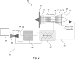
Figure 2 is a schematic representation fuel system according to an embodiment. - With reference to
Figure 1 , a gas turbine engine is generally indicated at 10, having a principal and rotational axis 11. Theengine 10 comprises, in axial flow series, anair intake 12, apropulsive fan 13, an intermediate-pressure compressor 14, a high-pressure compressor 15,combustion section 16, a high-pressure turbine 17, an intermediate-pressure turbine 18, a low-pressure turbine 19 and anexhaust nozzle 20. Anacelle 21 generally surrounds theengine 10 and defines both theintake 12 and theexhaust nozzle 20. - The
gas turbine engine 10 works in the conventional manner so that air entering theintake 12 is accelerated by thefan 13 to produce two air flows: a first air flow into the intermediate-pressure compressor 14 and a second air flow which passes through abypass duct 22 to provide propulsive thrust. The intermediate-pressure compressor 14 compresses the air flow directed into it before delivering that air to the high-pressure compressor 15 where further compression takes place. - The compressed air exhausted from the high-
pressure compressor 15 is directed into thecombustion equipment 16 where it is mixed with fuel and the mixture combusted. The resultant hot combustion products then expand through, and thereby drive the high-, intermediate- and low-pressure turbines nozzle 20 to provide additional propulsive thrust. The high-17, intermediate- 18 and low- 19 pressure turbines drive respectively the high-pressure compressor 15, intermediate-pressure compressor 14 andfan 13, each by suitable interconnecting shaft. - With reference to
Figure 2 , thegas turbine engine 10 is shown connected to afuel system 30 according to an exemplary arrangement of the present invention. Thefuel system 30 and thegas turbine engine 10 may be configured to be provided in a vehicle (e.g., an aircraft). - The
fuel system 30 includes afuel pump 32, which is a turbo pump, arranged in fluid communication with afuel reservoir 34. Thefuel system 30 also includes a drivingturbine 36 configured to drive thefuel pump 32. The drivingturbine 36 is fluidly connected to a core exhaust (e.g., the nozzle 20) of thegas turbine engine 10, such that anair feed 38 from the core exhaust (e.g., a hot gas stream) is directed to drive the drivingturbine 36, and thereby drive thefuel pump 32. - By using the air feed 38 from the core exhaust of the
gas turbine engine 10 to drive the drivingturbine 36 which, in turn drives thefuel pump 32, the present inventors have found that thefuel pump 32 can be operated at rotational speeds high enough to pump liquid hydrogen within thegas turbine engine 10 without the need for traditional drives/gears and without the need for burning fuel to drive the drivingturbine 36. - The
fuel system 30 further includes afuel line 40 which fluidly connects thefuel pump 32 to thecombustion section 16 of thegas turbine engine 10. Aheat exchanger 42, of thefuel system 30, is arranged to provide thermal communication between thefuel line 40 and theair feed 38. In this way, theheat exchanger 42 effects cooling of the air within the air feed prior to it driving the drivingturbine 36. - The
heat exchanger 42 is provided downstream in core exhaust flow of thecore exhaust nozzle 20, and upstream in core exhaust flow of theturbine 36. Consequently, the temperature of the exhaust flow is reduced, while pressure may be retained, thereby reducing the material requirements for theturbine 36. Theheat exchanger 42 is provided downstream, in fuel flow of thefuel pump 32, and upstream in fuel flow of thecombustor 16. As such, the fuel is heated by theheat exchanger 42 after it is pumped while enables the fuel to be pumped at a lower temperature (thereby reducing the work required to raise the pressure of the fuel), while ensuring the required combustion temperature is reached prior to delivery to thecombustor 16. Additionally, in view of the location of the heat exchanger, the temperature difference between the hot exhaust gases and pumped fuel is maximised, thereby reducing the size of the heat exchanger for a given final temperature of the fuel prior to delivery to thecombustor 16. - By using heat exchange from the air feed 38 from the core exhaust of the
gas turbine engine 10 to heat fuel within thefuel line 40, the fuel can be heated to a temperature required for entry into thecombustion section 16 of thegas turbine engine 10, which increases the efficiency of theengine 10 whilst minimising the additional heat input into thefuel system 30. - The
fuel system 30 shown inFigure 2 , includes both the drivingturbine 36 and theheat exchanger 42. Accordingly, the air feed 38 from the core exhaust of theengine 10 can both drive the drivingturbine 36 to effect pumping of the fuel and pre-heat the pumped fuel prior to entry into thecombustion section 16 of thegas turbine engine 10. - The
fuel reservoir 34 is configured to contain liquid hydrogen. For example, thefuel reservoir 34 may be a cryogenic fuel reservoir, as would be understood by the skilled person. Accordingly, the cryogenic fuel reservoir may be configured (e.g., thermally insulated) such that it can store liquid hydrogen at a temperature of around 25K. A portion of thefuel line 40 which connects thefuel reservoir 34 to thefuel pump 32 includes cryogenic pipework, which can withstand and maintain the cold temperature of the liquid hydrogen. Thefuel reservoir 34 is located proximate (e.g., adjacent to the fuel pump 32) in order to minimise the pipework (e.g., the cryogenic pipework), between thefuel reservoir 34 and thefuel pump 32. - The
fuel system 30 includes afuel metering unit 46 for metering flow of fuel to thefuel pump 32. Thefuel metering unit 46 is fluidly coupled to thefuel line 40 upstream from theheat exchanger 42, as shown inFigure 2 . - The features disclosed in the foregoing description, or in the following claims, or in the accompanying drawings, expressed in their specific forms or in terms of a means for performing the disclosed function, or a method or process for obtaining the disclosed results, as appropriate, may, separately, or in any combination of such features, be utilised for realising the invention in diverse forms thereof.
- While the invention has been described in conjunction with the exemplary embodiments described above, many equivalent modifications and variations will be apparent to those skilled in the art when given this disclosure. Accordingly, the exemplary embodiments of the invention set forth above are considered to be illustrative and not limiting. Various changes to the described embodiments may be made without departing from the spirit and scope of the invention.
- For the avoidance of any doubt, any theoretical explanations provided herein are provided for the purposes of improving the understanding of a reader. The inventors do not wish to be bound by any of these theoretical explanations.
- Any section headings used herein are for organizational purposes only and are not to be construed as limiting the subject matter described.
- Throughout this specification, including the claims which follow, unless the context requires otherwise, the word "comprise" and "include", and variations such as "comprises", "comprising", and "including" will be understood to imply the inclusion of a stated integer or step or group of integers or steps but not the exclusion of any other integer or step or group of integers or steps.
- It must be noted that, as used in the specification and the appended claims, the singular forms "a," "an," and "the" include plural referents unless the context clearly dictates otherwise. Ranges may be expressed herein as from "about" one particular value, and/or to "about" another particular value. When such a range is expressed, another embodiment includes from the one particular value and/or to the other particular value. Similarly, when values are expressed as approximations, by the use of the antecedent "about," it will be understood that the particular value forms another embodiment. The term "about" in relation to a numerical value is optional and means for example +/- 10%.
Claims (12)
- A fuel system (30) for a gas turbine engine (10) having a core exhaust (20) and a combustion section (16), the system comprising:a fuel pump (32) for fluid communication with a fuel reservoir (34);a driving turbine (36) for driving the fuel pump (32); andan air feed (38) to drive the driving turbine (36), the air feed being fluidly connectable to the core exhaust (20) of the gas turbine engine (10).
- A fuel system according to claim 1 further comprising a fuel line (40) from the fuel pump (32) for fluid communication with the combustion section (16) of the gas turbine engine (10), the fuel line (40) being in thermal communication with the air feed (38) within a heat exchanger (42).
- A fuel system for a gas turbine engine (10) having a core exhaust (20) and a combustion section (16), the system comprising:a fuel pump (32) for fluid communication with a fuel reservoir;a fuel line (40) from the fuel pump (32) for fluid communication with the combustion section (16) of the gas turbine engine (10); andan air feed (38) to a heat exchanger (42), the air feed (38) being fluidly connectable to the core exhaust (20) of the gas turbine engine (10), wherein the fuel line (40) is in thermal communication with the air feed (38) within the heat exchanger (42).
- A fuel system according to claim 3 further comprising a driving turbine (36) for driving the fuel pump (32), the driving turbine (32) being driven by the air feed (38).
- A fuel system according to any one of the preceding claims wherein the fuel pump comprises a turbo pump (32).
- A fuel system according to any one of the preceding claims further comprising a cryogenic fuel reservoir.
- An aircraft comprising a fuel system (30) according to any one of the preceding claims.
- A method of operating a fuel system (30) in a gas turbine engine (10) having a core exhaust (20) and a combustion section (16), the method comprising:powering a driving turbine (36) using an air feed (38) from the core exhaust (20) of the gas turbine engine (10);providing fuel to a fuel pump (32) from a fuel reservoir; anddriving the fuel pump (32) using the air-powered driving turbine (36).
- A method according to claim 8 further comprising:driving the fuel pump (32) to pump fuel along a fuel line (40) from the fuel pump (32) to the combustion section (16) of the gas turbine engine (10); andheating the fuel within the fuel line (40) using heat from the air feed (38) within a heat exchanger (42).
- A method of operating a fuel system in a gas turbine engine having a core exhaust (20) and a combustion section (16), the method comprising:providing fuel to a fuel pump (32) from a fuel reservoir;driving the fuel pump (32) to pump fuel along a fuel line (40) from the fuel pump (32) to the combustion section (16) of the gas turbine engine (10); andheating the fuel in the fuel line(40) within a heat exchanger (42) using heat from an air feed (38) from the core exhaust (20) of the gas turbine engine (10).
- A method according to claim 10 further comprising:powering a driving turbine (36) using the air feed (38) from the core exhaust (20) of the gas turbine engine (10); anddriving the fuel pump (32) using the air-powered driving turbine (36).
- A method according to any one of claims 8 to 11 wherein the fuel is liquid hydrogen.
Applications Claiming Priority (1)
| Application Number | Priority Date | Filing Date | Title |
|---|---|---|---|
| GBGB2204068.7A GB202204068D0 (en) | 2022-03-23 | 2022-03-23 | Fuel system |
Publications (2)
| Publication Number | Publication Date |
|---|---|
| EP4249740A2 true EP4249740A2 (en) | 2023-09-27 |
| EP4249740A3 EP4249740A3 (en) | 2023-11-15 |
Family
ID=81344734
Family Applications (1)
| Application Number | Title | Priority Date | Filing Date |
|---|---|---|---|
| EP23158394.9A Pending EP4249740A3 (en) | 2022-03-23 | 2023-02-24 | Fuel system |
Country Status (2)
| Country | Link |
|---|---|
| EP (1) | EP4249740A3 (en) |
| GB (1) | GB202204068D0 (en) |
Family Cites Families (5)
| Publication number | Priority date | Publication date | Assignee | Title |
|---|---|---|---|---|
| DE3617915C1 (en) * | 1986-05-28 | 1987-09-17 | Messerschmitt Boelkow Blohm | Combination drive |
| US4989411A (en) * | 1988-12-22 | 1991-02-05 | Allied-Signal Inc. | Over the shaft fuel pumping system |
| DE3909050C1 (en) * | 1989-03-18 | 1990-08-16 | Messerschmitt-Boelkow-Blohm Gmbh, 8012 Ottobrunn, De | |
| JP2003166428A (en) * | 2001-11-30 | 2003-06-13 | Toshiba Corp | Gas turbine generator and gas fuel booster applied thereto |
| US9932124B2 (en) * | 2012-12-28 | 2018-04-03 | General Electric Company | Cryogenic fuel system and method for delivering fuel in an aircraft |
-
2022
- 2022-03-23 GB GBGB2204068.7A patent/GB202204068D0/en not_active Ceased
-
2023
- 2023-02-24 EP EP23158394.9A patent/EP4249740A3/en active Pending
Also Published As
| Publication number | Publication date |
|---|---|
| GB202204068D0 (en) | 2022-05-04 |
| US20230304441A1 (en) | 2023-09-28 |
| EP4249740A3 (en) | 2023-11-15 |
Similar Documents
| Publication | Publication Date | Title |
|---|---|---|
| US11047307B2 (en) | Hybrid expander cycle with intercooling and turbo-generator | |
| EP3978738B1 (en) | Hydrogen fuel vaporiser | |
| US10989117B2 (en) | Hybrid expander cycle with pre-compression cooling and turbo-generator | |
| EP3023615B1 (en) | Fuel pumping unit | |
| US20200141326A1 (en) | Gas turbine engine with differential gearbox | |
| US20230133397A1 (en) | Dual cycle intercooled hydrogen engine architecture | |
| US11828200B2 (en) | Hydrogen-oxygen fueled powerplant with water and heat recovery | |
| US11787548B2 (en) | Aircraft power plant with supercritical CO2 heat engine | |
| US9051873B2 (en) | Ceramic-to-metal turbine shaft attachment | |
| EP4249740A2 (en) | Fuel system | |
| US11982235B2 (en) | Fuel system | |
| EP4123146A1 (en) | Dual cycle intercooled engine architectures | |
| EP4249739A1 (en) | Fuel system | |
| RU2379532C1 (en) | Nuclear gas turbine aircraft engine | |
| EP4361420A1 (en) | Combined gas turbine engine and fuel cell | |
| US11773778B1 (en) | Air bottoming cycle air cycle system source | |
| US20240133340A1 (en) | Combined gas turbine engine and fuel cell | |
| EP4361419A1 (en) | Gas turbine engine fuel system | |
| US20240133343A1 (en) | Gas turbine engine fuel system | |
| RU2349775C1 (en) | Nuclear gas-turbine aviation engine | |
| EP4361418A1 (en) | Aircraft engine fuel system | |
| EP4303416A1 (en) | Turbo expanders for turbine engines having hydrogen fuel systems | |
| RU2095606C1 (en) | Engine utilizing energy of heated vapor of fuel | |
| CN116733607A (en) | Combination gas turbine engine and power electronics | |
| RU2336429C1 (en) | Nuclear gas turbine engine |
Legal Events
| Date | Code | Title | Description |
|---|---|---|---|
| PUAI | Public reference made under article 153(3) epc to a published international application that has entered the european phase |
Free format text: ORIGINAL CODE: 0009012 |
|
| STAA | Information on the status of an ep patent application or granted ep patent |
Free format text: STATUS: THE APPLICATION HAS BEEN PUBLISHED |
|
| AK | Designated contracting states |
Kind code of ref document: A2 Designated state(s): AL AT BE BG CH CY CZ DE DK EE ES FI FR GB GR HR HU IE IS IT LI LT LU LV MC ME MK MT NL NO PL PT RO RS SE SI SK SM TR |
|
| PUAL | Search report despatched |
Free format text: ORIGINAL CODE: 0009013 |
|
| AK | Designated contracting states |
Kind code of ref document: A3 Designated state(s): AL AT BE BG CH CY CZ DE DK EE ES FI FR GB GR HR HU IE IS IT LI LT LU LV MC ME MK MT NL NO PL PT RO RS SE SI SK SM TR |
|
| RIC1 | Information provided on ipc code assigned before grant |
Ipc: F02C 3/22 20060101ALI20231010BHEP Ipc: F02C 7/224 20060101AFI20231010BHEP |
|
| STAA | Information on the status of an ep patent application or granted ep patent |
Free format text: STATUS: REQUEST FOR EXAMINATION WAS MADE |
|
| 17P | Request for examination filed |
Effective date: 20231206 |
|
| RBV | Designated contracting states (corrected) |
Designated state(s): AL AT BE BG CH CY CZ DE DK EE ES FI FR GB GR HR HU IE IS IT LI LT LU LV MC ME MK MT NL NO PL PT RO RS SE SI SK SM TR |