EP4249737A1 - Expansion kettle for vehicle cooling system and vehicle cooling system - Google Patents
Expansion kettle for vehicle cooling system and vehicle cooling system Download PDFInfo
- Publication number
- EP4249737A1 EP4249737A1 EP21938251.2A EP21938251A EP4249737A1 EP 4249737 A1 EP4249737 A1 EP 4249737A1 EP 21938251 A EP21938251 A EP 21938251A EP 4249737 A1 EP4249737 A1 EP 4249737A1
- Authority
- EP
- European Patent Office
- Prior art keywords
- liquid
- tank body
- diversion channel
- cooling system
- vehicle cooling
- Prior art date
- Legal status (The legal status is an assumption and is not a legal conclusion. Google has not performed a legal analysis and makes no representation as to the accuracy of the status listed.)
- Granted
Links
Images


Classifications
-
- F—MECHANICAL ENGINEERING; LIGHTING; HEATING; WEAPONS; BLASTING
- F01—MACHINES OR ENGINES IN GENERAL; ENGINE PLANTS IN GENERAL; STEAM ENGINES
- F01P—COOLING OF MACHINES OR ENGINES IN GENERAL; COOLING OF INTERNAL-COMBUSTION ENGINES
- F01P11/00—Component parts, details, or accessories not provided for in, or of interest apart from, groups F01P1/00 - F01P9/00
- F01P11/02—Liquid-coolant filling, overflow, venting, or draining devices
- F01P11/029—Expansion reservoirs
-
- B—PERFORMING OPERATIONS; TRANSPORTING
- B60—VEHICLES IN GENERAL
- B60K—ARRANGEMENT OR MOUNTING OF PROPULSION UNITS OR OF TRANSMISSIONS IN VEHICLES; ARRANGEMENT OR MOUNTING OF PLURAL DIVERSE PRIME-MOVERS IN VEHICLES; AUXILIARY DRIVES FOR VEHICLES; INSTRUMENTATION OR DASHBOARDS FOR VEHICLES; ARRANGEMENTS IN CONNECTION WITH COOLING, AIR INTAKE, GAS EXHAUST OR FUEL SUPPLY OF PROPULSION UNITS IN VEHICLES
- B60K11/00—Arrangement in connection with cooling of propulsion units
- B60K11/02—Arrangement in connection with cooling of propulsion units with liquid cooling
-
- F—MECHANICAL ENGINEERING; LIGHTING; HEATING; WEAPONS; BLASTING
- F01—MACHINES OR ENGINES IN GENERAL; ENGINE PLANTS IN GENERAL; STEAM ENGINES
- F01P—COOLING OF MACHINES OR ENGINES IN GENERAL; COOLING OF INTERNAL-COMBUSTION ENGINES
- F01P11/00—Component parts, details, or accessories not provided for in, or of interest apart from, groups F01P1/00 - F01P9/00
- F01P11/02—Liquid-coolant filling, overflow, venting, or draining devices
- F01P11/028—Deaeration devices
-
- H—ELECTRICITY
- H01—ELECTRIC ELEMENTS
- H01M—PROCESSES OR MEANS, e.g. BATTERIES, FOR THE DIRECT CONVERSION OF CHEMICAL ENERGY INTO ELECTRICAL ENERGY
- H01M10/00—Secondary cells; Manufacture thereof
- H01M10/60—Heating or cooling; Temperature control
- H01M10/61—Types of temperature control
- H01M10/613—Cooling or keeping cold
-
- H—ELECTRICITY
- H01—ELECTRIC ELEMENTS
- H01M—PROCESSES OR MEANS, e.g. BATTERIES, FOR THE DIRECT CONVERSION OF CHEMICAL ENERGY INTO ELECTRICAL ENERGY
- H01M10/00—Secondary cells; Manufacture thereof
- H01M10/60—Heating or cooling; Temperature control
- H01M10/62—Heating or cooling; Temperature control specially adapted for specific applications
- H01M10/625—Vehicles
Definitions
- the present invention pertains to the technical field of vehicle cooling systems, and relates to an expansion tank for a vehicle cooling system and a vehicle cooling system.
- a cooling system in a vehicle generally adopts such a form that a radiator is used to perform liquid-gas separation on a coolant liquid circulated in the cooling system, an air outlet arranged at the highest position of a water chamber in the radiator is connected with an expansion tank, and a water refill pipe of the expansion tank forms a parallel circuit with a main cooling water circuit, such that air separated by the radiator is brought into the expansion tank and stored in the expansion tank.
- a battery cooling system is not provided with a radiator, and orientation of the pipeline is complicated, resulting in easy accumulation of air. Therefore, rapid degassing is particularly important for a battery cooling circuit.
- a special liquid-gas separator is connected in series to a main circuit of the cooling system for degassing, the degassing effect depends on the design of the liquid-gas separator, and the addition of the liquid-gas separator leads to a sharp rise in the cost and weight of the whole cooling system.
- the degassing structure of the vehicle cooling system needs to be optimized.
- An objective of the present invention is to provide an expansion tank for a vehicle cooling system and a vehicle cooling system, which can realize automatic degassing of the cooling system, and can reduce cost and weight compared with the existing degassing method.
- the objective of the present invention can be realized by the following technical solution.
- An expansion tank for a vehicle cooling system includes a tank body and a chamber provided inside the tank body, where a liquid inlet and a liquid outlet are provided on the tank body, a diversion channel matched with a bottom of the tank body is provided inside the tank body, both ends of the diversion channel are respectively connected with the liquid inlet and the liquid outlet, a vent hole and a liquid refill hole are sequentially provided on a side of the diversion channel in a flow direction of a coolant liquid, and the vent hole and the liquid refill hole are both communicated with the chamber.
- the expansion tank is directly connected in series to a main cooling circuit of a motor, and the coolant liquid enters the expansion tank through the liquid inlet, flows through the diversion channel, and then is discharged from the expansion tank through the liquid outlet.
- Air in the coolant liquid leaves the diversion channel through the vent hole along with part of the coolant liquid and then enters the chamber inside the tank body, and part of the coolant liquid stored in the chamber enters the diversion channel through the liquid refill hole so as to automatically separate the air from the cooling system and maintain a steady flow of coolant liquid in the main cooling circuit.
- the vent hole and the liquid refill hole are provided on the side of the diversion channel, thereby avoiding NVH problems caused by liquid level fluctuations.
- the air separated from the cooling system is stored in the expansion tank.
- a pressure cover is provided on the top of the expansion tank. When the coolant liquid inside the expansion tank is insufficient, the pressure cover on the top of the expansion tank needs to be opened for refill of the coolant liquid.
- a pressure valve is provided on the pressure cover. When the air in the expansion tank reaches a certain amount, the air pressure may rise and the pressure valve on the pressure cover may be opened.
- the diversion channel is in an arc bent outward, the vent hole is provided on an outer side of the diversion channel, and the liquid refill hole is provided on an inner side of the diversion channel.
- the vent hole is provided on a top of the outer side of the diversion channel, and the liquid refill hole is provided on a bottom of the inner side of the diversion channel. Since the air can automatically rise up and exist above a liquid level of the coolant liquid, the vent hole is provide on the top of the outer side of the diversion channel, such that the air can be easily discharged. After the air is discharged, the coolant liquid is refilled through the liquid refill hole until the whole cooling system is filled with liquid.
- the vent hole and the liquid refill hole can be square holes, round holes, notches, and the like.
- the liquid inlet is provided on a side of the tank body, and the liquid outlet is provided on the bottom of the tank body.
- the vent hole is designed by using the outer rounded corner as a positive pressure area, and the liquid refill hole is designed by using the inner rounded corner as a negative pressure area, such that the venting and liquid refilling functions are realized.
- the diversion channel is a linear diversion channel, and the vent hole and the liquid refill hole are arranged on the same side of the diversion channel.
- a turbulence structure is provided on the bottom of the tank body, so as to facilitate the venting and liquid refilling functions.
- the turbulence structure includes a protrusion which is provided on the bottom of the tank body and protrudes upwards, where the protrusion is matched with a bottom of the diversion channel, and is located between the vent hole and the liquid refill hole.
- the protrusion on the bottom of the tank body as the turbulence structure, mainly acts to increase the resistance at a certain position, thereby changing the flow field inside the diversion channel.
- liquid inlet and the liquid outlet are coaxially arranged.
- a plurality of partitions are provided in the chamber to divide the chamber into a plurality of cavities which are communicated with each other, and the vent hole and the liquid refill hole are respectively connected with different cavities.
- the partitions can strengthen the tank body. Meanwhile, the partitions can divide the chamber into the plurality of cavities, and the partitions are provided with holes which can communicate two adjacent cavities.
- the cavities include a vent cavity and a liquid refill cavity, the vent hole is connected with the vent cavity and the liquid refill hole is connected with the liquid refill cavity, and the vent cavity is separated from the liquid refill cavity by the partition.
- the turbulence structure matched with the bottom of the diversion channel is provided on the bottom of the tank body, and the holes are arranged on the same side of the diversion channel, such that the automatic liquid-gas separation is realized.
- a clamping groove is provided on the diversion channel, and a clamping plate matched with the clamping groove is provided inside the tank body.
- the diversion channel is installed on the clamping plate through the clamping groove so as to realize clamping of the diversion channel, and the diversion channel just connects the liquid inlet with the liquid outlet after clamping, thereby realizing the assembly of the diversion channel inside the tank body.
- the tank body includes an upper tank body and a lower tank body, and the liquid inlet, the liquid outlet and the diversion channel are all provided on the lower tank body.
- the diversion channel is assembled on the lower tank body, and then the lower tank body is welded to the upper tank body.
- a vehicle cooling system includes the expansion tank.
- the present invention has the following characteristics.
- 1-tank body 101-upper tank body, 102-lower tank body, 2-chamber, 3-liquid inlet, 4-liquid outlet, 5-diversion channel, 6-vent hole, 7-liquid refill hole, 8-protrusion, 9-partition, 10-clamping groove.
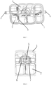
- a vehicle cooling system includes an expansion tank for the vehicle cooling system as shown in FIG. 5 .
- the expansion tank includes a tank body 1 and a chamber 2 provided inside the tank body 1.
- a liquid inlet 3 and a liquid outlet 4 are provided on the tank body 1.
- a diversion channel 5 matched with a bottom of the tank body 1 is provided inside the tank body 1, and both ends of the diversion channel 5 are respectively connected with the liquid inlet 3 and the liquid outlet 4.
- a vent hole 6 and a liquid refill hole 7 are sequentially provided on a side of the diversion channel 5 in a flow direction of a coolant liquid, and the vent hole 6 and the liquid refill hole 7 are both communicated with the chamber 2.
- the diversion channel 5 is in an arc bent outward
- the vent hole 6 is provided on an outer side of the diversion channel 5
- the liquid refill hole 7 is provided on an inner side of the diversion channel 5.
- the vent hole 6 is provided on a top of the outer side of the diversion channel 5, and the liquid refill hole 7 is provided on a bottom of the inner side of the diversion channel 5.
- the liquid inlet 3 is provided on a side of the tank body 1, and the liquid outlet 4 is provided on the bottom of the tank body 1.
- a plurality of partitions 9 are provided in the chamber 2 to divide the chamber 2 into a plurality of cavities which are communicated with each other.
- a clamping groove 10 is provided on the diversion channel 5, and a clamping plate matched with the clamping groove 10 is provided inside the tank body 1.
- the tank body 1 includes an upper tank body 101 and a lower tank body 102, and the liquid inlet 3, the liquid outlet 4 and the diversion channel 5 are all provided on the lower tank body 102.
- the vent hole 6 is designed by using the outer rounded corner as a positive pressure area
- the liquid refill hole 7 is designed by using the inner rounded corner as a negative pressure area, such that the venting and liquid refilling functions are realized.
- a vehicle cooling system includes an expansion tank for the vehicle cooling system as shown in FIG. 10 .
- the expansion tank includes a tank body 1 and a chamber 2 provided inside the tank body 1.
- a liquid inlet 3 and a liquid outlet 4 are provided on the tank body 1.
- a diversion channel 5 matched with a bottom of the tank body 1 is provided inside the tank body 1, and both ends of the diversion channel 5 are respectively connected with the liquid inlet 3 and the liquid outlet 4.
- a vent hole 6 and a liquid refill hole 7 are sequentially provided on a side of the diversion channel 5 in a flow direction of a coolant liquid, and the vent hole 6 and the liquid refill hole 7 are both communicated with the chamber 2.
- the diversion channel 5 is a linear diversion channel, and the vent hole 6 and the liquid refill hole 7 are arranged on the same side of the diversion channel 5.
- a turbulence structure is provided on the bottom of the tank body 1.
- the turbulence structure includes a protrusion 8 which is provided on the bottom of the tank body 1 and protrudes upwards, where the protrusion 8 is matched with a bottom of the diversion channel 5, and is located between the vent hole 6 and the liquid refill hole 7.
- the liquid inlet 3 and the liquid outlet 4 are coaxially arranged.
- a plurality of partitions 9 are provided in the chamber 2 to divide the chamber 2 into a plurality of cavities which are communicated with each other, and the vent hole 6 and the liquid refill hole 7 are respectively connected with different cavities.
- a clamping groove 10 is provided on the diversion channel 5, and a clamping plate matched with the clamping groove 10 is provided inside the tank body 1.
- the tank body 1 includes an upper tank body 101 and a lower tank body 102, and the liquid inlet 3, the liquid outlet 4 and the diversion channel 5 are all provided on the lower tank body 102.
- the turbulence structure matched with the bottom of the diversion channel 5 is provided on the bottom of the tank body 1, and the vent hole 6 and the liquid refill hole 7 are arranged on the same side of the diversion channel 5, such that the automatic liquid-gas separation is realized.
- the present invention can realize the automatic separation of the air from the coolant liquid and the automatic refill of the coolant liquid by providing the diversion channel 5 connecting the liquid inlet 3 and the liquid outlet 4 inside the tank body 1, and sequentially providing the vent hole 6 and the liquid refill hole 7 on the side of the diversion channel 5 in the flow direction of the coolant liquid. Since the expansion tank is directly connected in series to the main cooling circuit of the motor, the cost input and arrangement space of pipelines, pipe clamps, and liquid-gas separators are reduced, and the weight of the cooling system is also reduced.
- the diversion channel 5 can be designed in an arc bent outward or in a linear form so as to be suitable for different expansion tanks, allowing for good flexibility.
Landscapes
- Engineering & Computer Science (AREA)
- Chemical & Material Sciences (AREA)
- Combustion & Propulsion (AREA)
- Mechanical Engineering (AREA)
- General Engineering & Computer Science (AREA)
- Transportation (AREA)
- Manufacturing & Machinery (AREA)
- Chemical Kinetics & Catalysis (AREA)
- Electrochemistry (AREA)
- General Chemical & Material Sciences (AREA)
- Cooling, Air Intake And Gas Exhaust, And Fuel Tank Arrangements In Propulsion Units (AREA)
- Air-Conditioning For Vehicles (AREA)
Abstract
Description
- The present invention pertains to the technical field of vehicle cooling systems, and relates to an expansion tank for a vehicle cooling system and a vehicle cooling system.
- At present, a cooling system in a vehicle generally adopts such a form that a radiator is used to perform liquid-gas separation on a coolant liquid circulated in the cooling system, an air outlet arranged at the highest position of a water chamber in the radiator is connected with an expansion tank, and a water refill pipe of the expansion tank forms a parallel circuit with a main cooling water circuit, such that air separated by the radiator is brought into the expansion tank and stored in the expansion tank.
- However, for a new energy vehicle such as a battery electric vehicle, a battery cooling system is not provided with a radiator, and orientation of the pipeline is complicated, resulting in easy accumulation of air. Therefore, rapid degassing is particularly important for a battery cooling circuit. At present, in some vehicles, a special liquid-gas separator is connected in series to a main circuit of the cooling system for degassing, the degassing effect depends on the design of the liquid-gas separator, and the addition of the liquid-gas separator leads to a sharp rise in the cost and weight of the whole cooling system.
- Therefore, the degassing structure of the vehicle cooling system needs to be optimized.
- An objective of the present invention is to provide an expansion tank for a vehicle cooling system and a vehicle cooling system, which can realize automatic degassing of the cooling system, and can reduce cost and weight compared with the existing degassing method.
- The objective of the present invention can be realized by the following technical solution.
- An expansion tank for a vehicle cooling system includes a tank body and a chamber provided inside the tank body, where a liquid inlet and a liquid outlet are provided on the tank body, a diversion channel matched with a bottom of the tank body is provided inside the tank body, both ends of the diversion channel are respectively connected with the liquid inlet and the liquid outlet, a vent hole and a liquid refill hole are sequentially provided on a side of the diversion channel in a flow direction of a coolant liquid, and the vent hole and the liquid refill hole are both communicated with the chamber. The expansion tank is directly connected in series to a main cooling circuit of a motor, and the coolant liquid enters the expansion tank through the liquid inlet, flows through the diversion channel, and then is discharged from the expansion tank through the liquid outlet. Air in the coolant liquid leaves the diversion channel through the vent hole along with part of the coolant liquid and then enters the chamber inside the tank body, and part of the coolant liquid stored in the chamber enters the diversion channel through the liquid refill hole so as to automatically separate the air from the cooling system and maintain a steady flow of coolant liquid in the main cooling circuit. The vent hole and the liquid refill hole are provided on the side of the diversion channel, thereby avoiding NVH problems caused by liquid level fluctuations.
- The air separated from the cooling system is stored in the expansion tank. A pressure cover is provided on the top of the expansion tank. When the coolant liquid inside the expansion tank is insufficient, the pressure cover on the top of the expansion tank needs to be opened for refill of the coolant liquid. A pressure valve is provided on the pressure cover. When the air in the expansion tank reaches a certain amount, the air pressure may rise and the pressure valve on the pressure cover may be opened.
- Furthermore, the diversion channel is in an arc bent outward, the vent hole is provided on an outer side of the diversion channel, and the liquid refill hole is provided on an inner side of the diversion channel.
- Furthermore, the vent hole is provided on a top of the outer side of the diversion channel, and the liquid refill hole is provided on a bottom of the inner side of the diversion channel. Since the air can automatically rise up and exist above a liquid level of the coolant liquid, the vent hole is provide on the top of the outer side of the diversion channel, such that the air can be easily discharged. After the air is discharged, the coolant liquid is refilled through the liquid refill hole until the whole cooling system is filled with liquid.
- Preferably, the vent hole and the liquid refill hole can be square holes, round holes, notches, and the like.
- Furthermore, the liquid inlet is provided on a side of the tank body, and the liquid outlet is provided on the bottom of the tank body.
- In this structure, for fluid at the corner of the arc-shaped diversion channel, the vent hole is designed by using the outer rounded corner as a positive pressure area, and the liquid refill hole is designed by using the inner rounded corner as a negative pressure area, such that the venting and liquid refilling functions are realized.
- Alternatively, the diversion channel is a linear diversion channel, and the vent hole and the liquid refill hole are arranged on the same side of the diversion channel. A turbulence structure is provided on the bottom of the tank body, so as to facilitate the venting and liquid refilling functions.
- Furthermore, the turbulence structure includes a protrusion which is provided on the bottom of the tank body and protrudes upwards, where the protrusion is matched with a bottom of the diversion channel, and is located between the vent hole and the liquid refill hole. The protrusion on the bottom of the tank body, as the turbulence structure, mainly acts to increase the resistance at a certain position, thereby changing the flow field inside the diversion channel. In application, when the coolant liquid flows in the diversion channel, part of the coolant liquid containing air flows out of the diversion channel through the vent hole due to the resistance and necking effect of the protrusion, and the other part of the coolant liquid flowing through the protrusion is subject to the reduced resistance, while the inner diameter of the channel is increased, such that the coolant liquid in the chamber is sucked into the diversion channel through the liquid refill pipe.
- Furthermore, the liquid inlet and the liquid outlet are coaxially arranged.
- Furthermore, a plurality of partitions are provided in the chamber to divide the chamber into a plurality of cavities which are communicated with each other, and the vent hole and the liquid refill hole are respectively connected with different cavities. The partitions can strengthen the tank body. Meanwhile, the partitions can divide the chamber into the plurality of cavities, and the partitions are provided with holes which can communicate two adjacent cavities. The cavities include a vent cavity and a liquid refill cavity, the vent hole is connected with the vent cavity and the liquid refill hole is connected with the liquid refill cavity, and the vent cavity is separated from the liquid refill cavity by the partition.
- In this structure, the turbulence structure matched with the bottom of the diversion channel is provided on the bottom of the tank body, and the holes are arranged on the same side of the diversion channel, such that the automatic liquid-gas separation is realized.
- Furthermore, a clamping groove is provided on the diversion channel, and a clamping plate matched with the clamping groove is provided inside the tank body. The diversion channel is installed on the clamping plate through the clamping groove so as to realize clamping of the diversion channel, and the diversion channel just connects the liquid inlet with the liquid outlet after clamping, thereby realizing the assembly of the diversion channel inside the tank body.
- Furthermore, the tank body includes an upper tank body and a lower tank body, and the liquid inlet, the liquid outlet and the diversion channel are all provided on the lower tank body. During assembly, the diversion channel is assembled on the lower tank body, and then the lower tank body is welded to the upper tank body.
- A vehicle cooling system includes the expansion tank.
- Compared with the related art, the present invention has the following characteristics.
- 1) The automatic separation of the air from the coolant liquid and the automatic refill of the coolant liquid can be realized by providing the diversion channel connecting the liquid inlet and the liquid outlet inside the tank body, and sequentially providing the vent hole and the liquid refill hole on the side of the diversion channel in the flow direction of the coolant liquid.
- 2) Since the expansion tank is directly connected in series to the main cooling circuit of the motor, the cost input and arrangement space of pipelines, pipe clamps, and liquid-gas separators are reduced, and the weight of the cooling system is also reduced.
- 3) The diversion channel can be designed in an arc bent outward or in a linear form so as to be suitable for different expansion tanks, allowing for good flexibility.
-
-
FIG. 1 is a schematic diagram illustrating a structure of a diversion channel according toEmbodiment 1. -
FIG. 2 is a schematic plan view illustrating a structure of a lower tank body according toEmbodiment 1. -
FIG. 3 is a schematic diagram illustrating a diversion channel assembled in a tank body according toEmbodiment 1. -
FIG. 4 is a schematic diagram illustrating principle of automatic degassing according toEmbodiment 1. -
FIG. 5 is a schematic exploded view illustrating a structure of an expansion tank according toEmbodiment 1. -
FIG. 6 is a schematic diagram illustrating a structure of a diversion channel according toEmbodiment 2. -
FIG. 7 is a schematic plan view illustrating a structure of a lower tank body according toEmbodiment 2. -
FIG. 8 is a schematic diagram illustrating a diversion channel assembled in a tank body according toEmbodiment 2. -
FIG. 9 is a schematic diagram illustrating principle of automatic degassing according toEmbodiment 2. -
FIG. 10 is a schematic exploded view illustrating a structure of an expansion tank according toEmbodiment 2. - 1-tank body, 101-upper tank body, 102-lower tank body, 2-chamber, 3-liquid inlet, 4-liquid outlet, 5-diversion channel, 6-vent hole, 7-liquid refill hole, 8-protrusion, 9-partition, 10-clamping groove.
- The present invention will be described in detail below in conjunction with the accompanying drawings and specific embodiments. This embodiment is implemented on the premise of the technical solution of the present invention, and detailed implementation and specific operation process are given, but the scope of protection of the present invention is not limited to the following embodiments.
- A vehicle cooling system includes an expansion tank for the vehicle cooling system as shown in
FIG. 5 . The expansion tank includes atank body 1 and achamber 2 provided inside thetank body 1. As shown inFIG. 2 , aliquid inlet 3 and a liquid outlet 4 are provided on thetank body 1. Adiversion channel 5 matched with a bottom of thetank body 1 is provided inside thetank body 1, and both ends of thediversion channel 5 are respectively connected with theliquid inlet 3 and the liquid outlet 4. Avent hole 6 and aliquid refill hole 7 are sequentially provided on a side of thediversion channel 5 in a flow direction of a coolant liquid, and thevent hole 6 and theliquid refill hole 7 are both communicated with thechamber 2. - As shown in
FIG. 1 ,FIG. 3 and FIG. 4 , thediversion channel 5 is in an arc bent outward, thevent hole 6 is provided on an outer side of thediversion channel 5, and theliquid refill hole 7 is provided on an inner side of thediversion channel 5. Thevent hole 6 is provided on a top of the outer side of thediversion channel 5, and theliquid refill hole 7 is provided on a bottom of the inner side of thediversion channel 5. Theliquid inlet 3 is provided on a side of thetank body 1, and the liquid outlet 4 is provided on the bottom of thetank body 1. - A plurality of
partitions 9 are provided in thechamber 2 to divide thechamber 2 into a plurality of cavities which are communicated with each other. - A clamping
groove 10 is provided on thediversion channel 5, and a clamping plate matched with the clampinggroove 10 is provided inside thetank body 1. - As shown in
FIG. 5 , thetank body 1 includes anupper tank body 101 and alower tank body 102, and theliquid inlet 3, the liquid outlet 4 and thediversion channel 5 are all provided on thelower tank body 102. - In this structure, for coolant liquid at the corner of the arc-shaped
diversion channel 5, thevent hole 6 is designed by using the outer rounded corner as a positive pressure area, and theliquid refill hole 7 is designed by using the inner rounded corner as a negative pressure area, such that the venting and liquid refilling functions are realized. - A vehicle cooling system includes an expansion tank for the vehicle cooling system as shown in
FIG. 10 . The expansion tank includes atank body 1 and achamber 2 provided inside thetank body 1. As shown inFIG. 7 , aliquid inlet 3 and a liquid outlet 4 are provided on thetank body 1. Adiversion channel 5 matched with a bottom of thetank body 1 is provided inside thetank body 1, and both ends of thediversion channel 5 are respectively connected with theliquid inlet 3 and the liquid outlet 4. Avent hole 6 and aliquid refill hole 7 are sequentially provided on a side of thediversion channel 5 in a flow direction of a coolant liquid, and thevent hole 6 and theliquid refill hole 7 are both communicated with thechamber 2. - As shown in
FIG. 6 ,FIG. 8 andFIG. 9 , thediversion channel 5 is a linear diversion channel, and thevent hole 6 and theliquid refill hole 7 are arranged on the same side of thediversion channel 5. A turbulence structure is provided on the bottom of thetank body 1. The turbulence structure includes aprotrusion 8 which is provided on the bottom of thetank body 1 and protrudes upwards, where theprotrusion 8 is matched with a bottom of thediversion channel 5, and is located between thevent hole 6 and theliquid refill hole 7. Theliquid inlet 3 and the liquid outlet 4 are coaxially arranged. A plurality ofpartitions 9 are provided in thechamber 2 to divide thechamber 2 into a plurality of cavities which are communicated with each other, and thevent hole 6 and theliquid refill hole 7 are respectively connected with different cavities. - A clamping
groove 10 is provided on thediversion channel 5, and a clamping plate matched with the clampinggroove 10 is provided inside thetank body 1. - As shown in
FIG. 10 , thetank body 1 includes anupper tank body 101 and alower tank body 102, and theliquid inlet 3, the liquid outlet 4 and thediversion channel 5 are all provided on thelower tank body 102. - In this structure, the turbulence structure matched with the bottom of the
diversion channel 5 is provided on the bottom of thetank body 1, and thevent hole 6 and theliquid refill hole 7 are arranged on the same side of thediversion channel 5, such that the automatic liquid-gas separation is realized. - As can be seen from the above embodiments, the present invention can realize the automatic separation of the air from the coolant liquid and the automatic refill of the coolant liquid by providing the
diversion channel 5 connecting theliquid inlet 3 and the liquid outlet 4 inside thetank body 1, and sequentially providing thevent hole 6 and theliquid refill hole 7 on the side of thediversion channel 5 in the flow direction of the coolant liquid. Since the expansion tank is directly connected in series to the main cooling circuit of the motor, the cost input and arrangement space of pipelines, pipe clamps, and liquid-gas separators are reduced, and the weight of the cooling system is also reduced. Thediversion channel 5 can be designed in an arc bent outward or in a linear form so as to be suitable for different expansion tanks, allowing for good flexibility. - The foregoing description of the embodiments is provided to facilitate the understanding and use of the invention by those ordinary skilled in the art. It will be apparent to those skilled in the art that various modifications can readily be made to these embodiments and that the general principles described herein can be applied to other embodiments without any creative efforts. Therefore, the present invention is not limited to the above embodiments, and any improvements and modifications made by those skilled in the art according to the disclosure of the present invention without departing from the scope of the present invention should fall within the scope of protection of the present invention.
Claims (11)
- An expansion tank for a vehicle cooling system, characterized in that,the expansion tank comprises a tank body (1) and a chamber (2) provided inside the tank body (1),a liquid inlet (3) and a liquid outlet (4) are provided on the tank body (1),a diversion channel (5) matched with a bottom of the tank body (1) is provided inside the tank body (1), and both ends of the diversion channel (5) are respectively connected with the liquid inlet (3) and the liquid outlet (4), anda vent hole (6) and a liquid refill hole (7) are sequentially provided on a side of the diversion channel (5) in a flow direction of a coolant liquid, and the vent hole (6) and the liquid refill hole (7) are both communicated with the chamber (2).
- The expansion tank for the vehicle cooling system according to claim 1, characterized in that, the diversion channel (5) is in an arc bent outward, the vent hole (6) is provided on an outer side of the diversion channel (5), and the liquid refill hole (7) is provided on an inner side of the diversion channel (5).
- The expansion tank for the vehicle cooling system according to claim 2, characterized in that, the vent hole (6) is provided on a top of the outer side of the diversion channel (5), and the liquid refill hole (7) is provided on a bottom of the inner side of the diversion channel (5).
- The expansion tank for the vehicle cooling system according to claim 2, characterized in that, the liquid inlet (3) is provided on a side of the tank body (1), and the liquid outlet (4) is provided on the bottom of the tank body (1).
- The expansion tank for the vehicle cooling system according to claim 1, characterized in that,the diversion channel (5) is a linear diversion channel, and the vent hole (6) and the liquid refill hole (7) are arranged on a same side of the diversion channel (5), anda turbulence structure is provided on the bottom of the tank body (1).
- The expansion tank for the vehicle cooling system according to claim 5, characterized in that, the turbulence structure comprises a protrusion (8) which is provided on the bottom of the tank body (1) and protrudes upwards, wherein the protrusion (8) is matched with a bottom of the diversion channel (5), and is located between the vent hole (6) and the liquid refill hole (7).
- The expansion tank for the vehicle cooling system according to claim 5, characterized in that, the liquid inlet (3) and the liquid outlet (4) are coaxially arranged.
- The expansion tank for the vehicle cooling system according to claim 5, characterized in that, a plurality of partitions (9) are provided in the chamber (2) to divide the chamber (2) into a plurality of cavities which are communicated with each other, and the vent hole (6) and the liquid refill hole (7) are respectively connected with different cavities.
- The expansion tank for the vehicle cooling system according to claim 1, characterized in that, a clamping groove (10) is provided on the diversion channel (5), and a clamping plate matched with the clamping groove (10) is provided inside the tank body (1).
- The expansion tank for the vehicle cooling system according to claim 1, characterized in that, the tank body (1) comprises an upper tank body (101) and a lower tank body (102), and the liquid inlet (3), the liquid outlet (4), and the diversion channel (5) are all provided on the lower tank body (102).
- A vehicle cooling system, characterized in that, the vehicle cooling system comprises the expansion tank according to any one of claims 1 to 10.
Applications Claiming Priority (1)
| Application Number | Priority Date | Filing Date | Title |
|---|---|---|---|
| PCT/CN2021/090143 WO2022226763A1 (en) | 2021-04-27 | 2021-04-27 | Expansion kettle for vehicle cooling system and vehicle cooling system |
Publications (4)
| Publication Number | Publication Date |
|---|---|
| EP4249737A1 true EP4249737A1 (en) | 2023-09-27 |
| EP4249737A4 EP4249737A4 (en) | 2024-03-27 |
| EP4249737B1 EP4249737B1 (en) | 2025-01-22 |
| EP4249737C0 EP4249737C0 (en) | 2025-01-22 |
Family
ID=83847629
Family Applications (1)
| Application Number | Title | Priority Date | Filing Date |
|---|---|---|---|
| EP21938251.2A Active EP4249737B1 (en) | 2021-04-27 | 2021-04-27 | Expansion kettle for vehicle cooling system and vehicle cooling system |
Country Status (5)
| Country | Link |
|---|---|
| US (1) | US12220981B2 (en) |
| EP (1) | EP4249737B1 (en) |
| KR (1) | KR102837772B1 (en) |
| CN (1) | CN117320909A (en) |
| WO (1) | WO2022226763A1 (en) |
Family Cites Families (21)
| Publication number | Priority date | Publication date | Assignee | Title |
|---|---|---|---|---|
| FR2247107A5 (en) * | 1973-10-05 | 1975-05-02 | Renault | |
| SE469140B (en) * | 1991-09-20 | 1993-05-17 | Volvo Ab | DEVICE FOR COMBINED STORAGE (16) AND EXPANSION BOILER (19) FOR A WATERFUL COMBUSTION ENGINE COOLING SYSTEM |
| DE19538239C1 (en) * | 1995-10-13 | 1997-04-24 | Daimler Benz Ag | Coolant flow in a cooling circuit of a liquid-cooled internal combustion engine |
| JPH09166023A (en) * | 1996-09-25 | 1997-06-24 | Hino Motors Ltd | Header tank used in engine cooler |
| US6123144A (en) * | 1997-04-15 | 2000-09-26 | Cummins Engine Company, Inc. | Integrated heat exchanger and expansion tank |
| DE102006014400B4 (en) * | 2006-02-02 | 2012-01-26 | Audi Ag | Expansion tank for a cooling system and cooling arrangement |
| GB2455743B (en) * | 2007-12-20 | 2012-10-10 | Ford Global Tech Llc | Cooling system expansion tank |
| US8397681B2 (en) * | 2009-09-02 | 2013-03-19 | International Engine Intellectual Property Company, Llc | Expansion tank for vehicle cooling system |
| DE102014018366A1 (en) * | 2014-12-10 | 2016-06-16 | Man Truck & Bus Ag | Expansion tank for the coolant of liquid-cooled internal combustion engines |
| JP6461364B2 (en) * | 2015-09-28 | 2019-01-30 | 本田技研工業株式会社 | Expansion tank |
| EP3225806B1 (en) * | 2016-03-30 | 2018-07-04 | FCA Italy S.p.A. | Expansion tank for a motor-vehicle cooling system |
| EP3255260B1 (en) | 2016-06-10 | 2019-04-24 | FCA Italy S.p.A. | Expansion tank for a motor vehicle cooling system |
| US10665908B2 (en) * | 2016-06-23 | 2020-05-26 | Tesla, Inc. | Heating and cooling reservoir for a battery powered vehicle |
| JP2018096321A (en) * | 2016-12-15 | 2018-06-21 | トヨタ自動車株式会社 | Reserve tank |
| CN206530395U (en) | 2016-12-22 | 2017-09-29 | 柯美汽车零部件(上海)有限公司 | A kind of expansion tank for power battery cooling system for electronic vehicle |
| CN206555009U (en) | 2017-03-24 | 2017-10-13 | 江西凯马百路佳客车有限公司 | With the expansion tank for removing bubble function in cooling system |
| CN107380000A (en) | 2017-08-14 | 2017-11-24 | 中能绿驰成都汽车科技有限公司 | A kind of car water kettle that can be vented body automatically |
| CN209369912U (en) | 2018-11-13 | 2019-09-10 | 上海汽车集团股份有限公司 | Electric vehicle cooling system expansion kettle |
| CN209637872U (en) | 2019-02-26 | 2019-11-15 | 宁波吉利汽车研究开发有限公司 | A kind of motor expansion box assembly |
| CN211573631U (en) | 2019-11-12 | 2020-09-25 | 宝能(广州)汽车研究院有限公司 | Expansion kettle, thermal management system and new energy automobile |
| CN215170326U (en) | 2021-03-09 | 2021-12-14 | 劳士领汽车配件(昆山)有限公司 | Car Expansion Kettle |
-
2021
- 2021-04-27 US US18/256,888 patent/US12220981B2/en active Active
- 2021-04-27 CN CN202180086399.8A patent/CN117320909A/en active Pending
- 2021-04-27 KR KR1020237037945A patent/KR102837772B1/en active Active
- 2021-04-27 WO PCT/CN2021/090143 patent/WO2022226763A1/en not_active Ceased
- 2021-04-27 EP EP21938251.2A patent/EP4249737B1/en active Active
Also Published As
| Publication number | Publication date |
|---|---|
| CN117320909A (en) | 2023-12-29 |
| US12220981B2 (en) | 2025-02-11 |
| KR102837772B1 (en) | 2025-07-24 |
| WO2022226763A1 (en) | 2022-11-03 |
| US20240092160A1 (en) | 2024-03-21 |
| KR20230159616A (en) | 2023-11-21 |
| EP4249737B1 (en) | 2025-01-22 |
| EP4249737C0 (en) | 2025-01-22 |
| EP4249737A4 (en) | 2024-03-27 |
Similar Documents
| Publication | Publication Date | Title |
|---|---|---|
| CN101245962A (en) | Air separator for low flow rate cooling systems | |
| EP4446573A1 (en) | Integrated expansion water tank, cooling system and automobile | |
| CN115298880B (en) | Expansion kettle, vehicle cooling system and vehicle | |
| KR102686296B1 (en) | Expansion canisters, cooling systems and automobiles | |
| AU659937B2 (en) | Compartmentalized fluid tank | |
| EP4249737A1 (en) | Expansion kettle for vehicle cooling system and vehicle cooling system | |
| CN113594113A (en) | Siphon type liquid drainage cold plate | |
| CN209637872U (en) | A kind of motor expansion box assembly | |
| JP7227865B2 (en) | reservoir tank | |
| CN112186288A (en) | Cooling device, power battery and car | |
| US20210001248A1 (en) | Reservoir tank | |
| CN111591127A (en) | Automobile water storage bottle | |
| CN105931683A (en) | Reactor pressure vessel external cooling natural circulation system and method | |
| CN114151187B (en) | Air backflow prevention device for vehicle fluid storage tank | |
| CN209650082U (en) | A battery expansion box assembly | |
| TWM563912U (en) | Two-stage oil-water separator | |
| CN210674312U (en) | High-efficient extraction device of environmental protection for chemistry experiments | |
| CN221412312U (en) | Liquid-liquid extraction separation device | |
| CN110397781A (en) | A kind of device of vapour liquid separator and oil tank liquid level control pile-up valve | |
| CN120462573B (en) | Tank structure and ship for reducing supercritical carbon dioxide drainage heat loss | |
| CN222451944U (en) | Water overflow tank and vehicle | |
| CN217649297U (en) | Auxiliary oil tank | |
| CN116587837B (en) | Vehicle thermal management liquid flow circulation system and vehicle | |
| CN116512855B (en) | Expansion kettle, thermal management system and new energy automobile | |
| CN221074423U (en) | Integrated degassing expansion water tank |
Legal Events
| Date | Code | Title | Description |
|---|---|---|---|
| STAA | Information on the status of an ep patent application or granted ep patent |
Free format text: STATUS: THE INTERNATIONAL PUBLICATION HAS BEEN MADE |
|
| PUAI | Public reference made under article 153(3) epc to a published international application that has entered the european phase |
Free format text: ORIGINAL CODE: 0009012 |
|
| STAA | Information on the status of an ep patent application or granted ep patent |
Free format text: STATUS: REQUEST FOR EXAMINATION WAS MADE |
|
| 17P | Request for examination filed |
Effective date: 20230620 |
|
| AK | Designated contracting states |
Kind code of ref document: A1 Designated state(s): AL AT BE BG CH CY CZ DE DK EE ES FI FR GB GR HR HU IE IS IT LI LT LU LV MC MK MT NL NO PL PT RO RS SE SI SK SM TR |
|
| A4 | Supplementary search report drawn up and despatched |
Effective date: 20240226 |
|
| RIC1 | Information provided on ipc code assigned before grant |
Ipc: H01M 10/625 20140101ALI20240220BHEP Ipc: H01M 10/613 20140101ALI20240220BHEP Ipc: B60L 58/26 20190101ALI20240220BHEP Ipc: B60K 11/02 20060101ALI20240220BHEP Ipc: F01P 11/02 20060101AFI20240220BHEP |
|
| DAV | Request for validation of the european patent (deleted) | ||
| DAX | Request for extension of the european patent (deleted) | ||
| GRAP | Despatch of communication of intention to grant a patent |
Free format text: ORIGINAL CODE: EPIDOSNIGR1 |
|
| STAA | Information on the status of an ep patent application or granted ep patent |
Free format text: STATUS: GRANT OF PATENT IS INTENDED |
|
| RIC1 | Information provided on ipc code assigned before grant |
Ipc: H01M 10/625 20140101ALI20240930BHEP Ipc: H01M 10/613 20140101ALI20240930BHEP Ipc: B60L 58/26 20190101ALI20240930BHEP Ipc: B60K 11/02 20060101ALI20240930BHEP Ipc: F01P 11/02 20060101AFI20240930BHEP |
|
| INTG | Intention to grant announced |
Effective date: 20241017 |
|
| GRAS | Grant fee paid |
Free format text: ORIGINAL CODE: EPIDOSNIGR3 |
|
| GRAA | (expected) grant |
Free format text: ORIGINAL CODE: 0009210 |
|
| STAA | Information on the status of an ep patent application or granted ep patent |
Free format text: STATUS: THE PATENT HAS BEEN GRANTED |
|
| AK | Designated contracting states |
Kind code of ref document: B1 Designated state(s): AL AT BE BG CH CY CZ DE DK EE ES FI FR GB GR HR HU IE IS IT LI LT LU LV MC MK MT NL NO PL PT RO RS SE SI SK SM TR |
|
| REG | Reference to a national code |
Ref country code: GB Ref legal event code: FG4D |
|
| REG | Reference to a national code |
Ref country code: CH Ref legal event code: EP |
|
| REG | Reference to a national code |
Ref country code: IE Ref legal event code: FG4D |
|
| REG | Reference to a national code |
Ref country code: DE Ref legal event code: R096 Ref document number: 602021025261 Country of ref document: DE |
|
| U01 | Request for unitary effect filed |
Effective date: 20250129 |
|
| U07 | Unitary effect registered |
Designated state(s): AT BE BG DE DK EE FI FR IT LT LU LV MT NL PT RO SE SI Effective date: 20250205 |
|
| U20 | Renewal fee for the european patent with unitary effect paid |
Year of fee payment: 5 Effective date: 20250321 |
|
| PG25 | Lapsed in a contracting state [announced via postgrant information from national office to epo] |
Ref country code: RS Free format text: LAPSE BECAUSE OF FAILURE TO SUBMIT A TRANSLATION OF THE DESCRIPTION OR TO PAY THE FEE WITHIN THE PRESCRIBED TIME-LIMIT Effective date: 20250422 |
|
| PG25 | Lapsed in a contracting state [announced via postgrant information from national office to epo] |
Ref country code: PL Free format text: LAPSE BECAUSE OF FAILURE TO SUBMIT A TRANSLATION OF THE DESCRIPTION OR TO PAY THE FEE WITHIN THE PRESCRIBED TIME-LIMIT Effective date: 20250122 |
|
| PG25 | Lapsed in a contracting state [announced via postgrant information from national office to epo] |
Ref country code: ES Free format text: LAPSE BECAUSE OF FAILURE TO SUBMIT A TRANSLATION OF THE DESCRIPTION OR TO PAY THE FEE WITHIN THE PRESCRIBED TIME-LIMIT Effective date: 20250122 |
|
| PG25 | Lapsed in a contracting state [announced via postgrant information from national office to epo] |
Ref country code: IS Free format text: LAPSE BECAUSE OF FAILURE TO SUBMIT A TRANSLATION OF THE DESCRIPTION OR TO PAY THE FEE WITHIN THE PRESCRIBED TIME-LIMIT Effective date: 20250522 Ref country code: NO Free format text: LAPSE BECAUSE OF FAILURE TO SUBMIT A TRANSLATION OF THE DESCRIPTION OR TO PAY THE FEE WITHIN THE PRESCRIBED TIME-LIMIT Effective date: 20250422 |
|
| PG25 | Lapsed in a contracting state [announced via postgrant information from national office to epo] |
Ref country code: HR Free format text: LAPSE BECAUSE OF FAILURE TO SUBMIT A TRANSLATION OF THE DESCRIPTION OR TO PAY THE FEE WITHIN THE PRESCRIBED TIME-LIMIT Effective date: 20250122 |
|
| PG25 | Lapsed in a contracting state [announced via postgrant information from national office to epo] |
Ref country code: GR Free format text: LAPSE BECAUSE OF FAILURE TO SUBMIT A TRANSLATION OF THE DESCRIPTION OR TO PAY THE FEE WITHIN THE PRESCRIBED TIME-LIMIT Effective date: 20250423 |
|
| PG25 | Lapsed in a contracting state [announced via postgrant information from national office to epo] |
Ref country code: SM Free format text: LAPSE BECAUSE OF FAILURE TO SUBMIT A TRANSLATION OF THE DESCRIPTION OR TO PAY THE FEE WITHIN THE PRESCRIBED TIME-LIMIT Effective date: 20250122 |
|
| PG25 | Lapsed in a contracting state [announced via postgrant information from national office to epo] |
Ref country code: CZ Free format text: LAPSE BECAUSE OF FAILURE TO SUBMIT A TRANSLATION OF THE DESCRIPTION OR TO PAY THE FEE WITHIN THE PRESCRIBED TIME-LIMIT Effective date: 20250122 |
|
| PG25 | Lapsed in a contracting state [announced via postgrant information from national office to epo] |
Ref country code: SK Free format text: LAPSE BECAUSE OF FAILURE TO SUBMIT A TRANSLATION OF THE DESCRIPTION OR TO PAY THE FEE WITHIN THE PRESCRIBED TIME-LIMIT Effective date: 20250122 |
|
| REG | Reference to a national code |
Ref country code: CH Ref legal event code: H13 Free format text: ST27 STATUS EVENT CODE: U-0-0-H10-H13 (AS PROVIDED BY THE NATIONAL OFFICE) Effective date: 20251125 |
|
| PLBE | No opposition filed within time limit |
Free format text: ORIGINAL CODE: 0009261 |
|
| STAA | Information on the status of an ep patent application or granted ep patent |
Free format text: STATUS: NO OPPOSITION FILED WITHIN TIME LIMIT |
|
| PG25 | Lapsed in a contracting state [announced via postgrant information from national office to epo] |
Ref country code: MC Free format text: LAPSE BECAUSE OF FAILURE TO SUBMIT A TRANSLATION OF THE DESCRIPTION OR TO PAY THE FEE WITHIN THE PRESCRIBED TIME-LIMIT Effective date: 20250122 |
|
| 26N | No opposition filed |
Effective date: 20251023 |
|
| PG25 | Lapsed in a contracting state [announced via postgrant information from national office to epo] |
Ref country code: CH Free format text: LAPSE BECAUSE OF NON-PAYMENT OF DUE FEES Effective date: 20250430 |
|
| U20 | Renewal fee for the european patent with unitary effect paid |
Year of fee payment: 6 Effective date: 20260303 |
|
| PGFP | Annual fee paid to national office [announced via postgrant information from national office to epo] |
Ref country code: GB Payment date: 20260203 Year of fee payment: 6 |
|
| PG25 | Lapsed in a contracting state [announced via postgrant information from national office to epo] |
Ref country code: IE Free format text: LAPSE BECAUSE OF NON-PAYMENT OF DUE FEES Effective date: 20250427 |