EP4249289A1 - Pneumatic tire for aircraft - Google Patents
Pneumatic tire for aircraft Download PDFInfo
- Publication number
- EP4249289A1 EP4249289A1 EP21894234.0A EP21894234A EP4249289A1 EP 4249289 A1 EP4249289 A1 EP 4249289A1 EP 21894234 A EP21894234 A EP 21894234A EP 4249289 A1 EP4249289 A1 EP 4249289A1
- Authority
- EP
- European Patent Office
- Prior art keywords
- tire
- belt
- equatorial plane
- width direction
- aircraft
- Prior art date
- Legal status (The legal status is an assumption and is not a legal conclusion. Google has not performed a legal analysis and makes no representation as to the accuracy of the status listed.)
- Granted
Links
Images


Classifications
-
- B—PERFORMING OPERATIONS; TRANSPORTING
- B60—VEHICLES IN GENERAL
- B60C—VEHICLE TYRES; TYRE INFLATION; TYRE CHANGING; CONNECTING VALVES TO INFLATABLE ELASTIC BODIES IN GENERAL; DEVICES OR ARRANGEMENTS RELATED TO TYRES
- B60C9/00—Reinforcements or ply arrangement of pneumatic tyres
- B60C9/18—Structure or arrangement of belts or breakers, crown-reinforcing or cushioning layers
- B60C9/28—Structure or arrangement of belts or breakers, crown-reinforcing or cushioning layers characterised by the belt or breaker dimensions or curvature relative to carcass
-
- B—PERFORMING OPERATIONS; TRANSPORTING
- B60—VEHICLES IN GENERAL
- B60C—VEHICLE TYRES; TYRE INFLATION; TYRE CHANGING; CONNECTING VALVES TO INFLATABLE ELASTIC BODIES IN GENERAL; DEVICES OR ARRANGEMENTS RELATED TO TYRES
- B60C9/00—Reinforcements or ply arrangement of pneumatic tyres
- B60C9/18—Structure or arrangement of belts or breakers, crown-reinforcing or cushioning layers
- B60C9/26—Folded plies
- B60C9/263—Folded plies further characterised by an endless zigzag configuration in at least one belt ply, i.e. no cut edge being present
-
- B—PERFORMING OPERATIONS; TRANSPORTING
- B60—VEHICLES IN GENERAL
- B60C—VEHICLE TYRES; TYRE INFLATION; TYRE CHANGING; CONNECTING VALVES TO INFLATABLE ELASTIC BODIES IN GENERAL; DEVICES OR ARRANGEMENTS RELATED TO TYRES
- B60C11/00—Tyre tread bands; Tread patterns; Anti-skid inserts
- B60C11/0083—Tyre tread bands; Tread patterns; Anti-skid inserts characterised by the curvature of the tyre tread
-
- B—PERFORMING OPERATIONS; TRANSPORTING
- B60—VEHICLES IN GENERAL
- B60C—VEHICLE TYRES; TYRE INFLATION; TYRE CHANGING; CONNECTING VALVES TO INFLATABLE ELASTIC BODIES IN GENERAL; DEVICES OR ARRANGEMENTS RELATED TO TYRES
- B60C9/00—Reinforcements or ply arrangement of pneumatic tyres
- B60C9/18—Structure or arrangement of belts or breakers, crown-reinforcing or cushioning layers
- B60C9/20—Structure or arrangement of belts or breakers, crown-reinforcing or cushioning layers built-up from rubberised plies each having all cords arranged substantially parallel
- B60C9/22—Structure or arrangement of belts or breakers, crown-reinforcing or cushioning layers built-up from rubberised plies each having all cords arranged substantially parallel the plies being arranged with all cords disposed along the circumference of the tyre
-
- B—PERFORMING OPERATIONS; TRANSPORTING
- B60—VEHICLES IN GENERAL
- B60C—VEHICLE TYRES; TYRE INFLATION; TYRE CHANGING; CONNECTING VALVES TO INFLATABLE ELASTIC BODIES IN GENERAL; DEVICES OR ARRANGEMENTS RELATED TO TYRES
- B60C9/00—Reinforcements or ply arrangement of pneumatic tyres
- B60C9/18—Structure or arrangement of belts or breakers, crown-reinforcing or cushioning layers
- B60C9/20—Structure or arrangement of belts or breakers, crown-reinforcing or cushioning layers built-up from rubberised plies each having all cords arranged substantially parallel
- B60C9/22—Structure or arrangement of belts or breakers, crown-reinforcing or cushioning layers built-up from rubberised plies each having all cords arranged substantially parallel the plies being arranged with all cords disposed along the circumference of the tyre
- B60C9/2204—Structure or arrangement of belts or breakers, crown-reinforcing or cushioning layers built-up from rubberised plies each having all cords arranged substantially parallel the plies being arranged with all cords disposed along the circumference of the tyre obtained by circumferentially narrow strip winding
-
- B—PERFORMING OPERATIONS; TRANSPORTING
- B60—VEHICLES IN GENERAL
- B60C—VEHICLE TYRES; TYRE INFLATION; TYRE CHANGING; CONNECTING VALVES TO INFLATABLE ELASTIC BODIES IN GENERAL; DEVICES OR ARRANGEMENTS RELATED TO TYRES
- B60C11/00—Tyre tread bands; Tread patterns; Anti-skid inserts
- B60C11/01—Shape of the shoulders between tread and sidewall, e.g. rounded, stepped or cantilevered
-
- B—PERFORMING OPERATIONS; TRANSPORTING
- B60—VEHICLES IN GENERAL
- B60C—VEHICLE TYRES; TYRE INFLATION; TYRE CHANGING; CONNECTING VALVES TO INFLATABLE ELASTIC BODIES IN GENERAL; DEVICES OR ARRANGEMENTS RELATED TO TYRES
- B60C2200/00—Tyres specially adapted for particular applications
- B60C2200/02—Tyres specially adapted for particular applications for aircrafts
Definitions
- This disclosure relates to a pneumatic tire for aircraft.
- the pneumatic tires for aircraft have been proposed: which have a pair of bead cores, a radial carcass comprising one or more carcass plies extending toroidally between the bead cores, and a belt layer as a tread reinforcement member on the radial outer side of the radial carcass in the tread portion;
- the above belt layer consists of a spiral belt layer made of ribbon-like organic fibers wound in an abbreviated circumferential direction, 5 degrees or less to the tire equatorial plane, and a zigzag belt layer made of ribbon-like organic fibers wound at an angle of 2 to 45 degrees to the tire equatorial plane and folded at both ends of the belt; and the shape of the outer surface of the tread has a predetermined step-down amount ⁇ at the intermediate land portion (PTL 1).
- appcable rim refers to the standard rim (Design Rim) in the applicable size as described or as may be described in the future in the latest edition of the AIRCRAFT YEAR BOOK or the latest edition of the EDI (Engineering Design Information for Aircraft Tires) published by TRA (The Tire and Rim Association, Inc.) in the United States (the 2017 editi on is used for numerical descriptions herein).
- TRA The Tire and Rim Association, Inc.
- TRA The Tire and Rim Association, Inc.
- prescribed internal pressure means the air pressure, i.e., maximum air pressure, corresponding to the maximum load capacity of a single wheel in the applicable size and ply rating, as described in the above standard.
- "prescribed internal pressure” shall mean the air pressure, i.e., maximum air pressure, corresponding to the maximum load capacity prescribed for each vehicle in which the tire is mounted.
- the above outer surface of the tire shall mean the hypothetical line assuming there are no grooves.
- the elastic modulus of the belt cord herein refers to the elastic modulus of a single cord (cN/dtex) calculated from the slope "s-s curve" when a single cord is elongated by 1.5% in accordance with the standard number JIS L 1017:2002, "Test Method for Chemical Fiber Tire Cords".
- This disclosure can provide a pneumatic tire for aircraft that can suppress the wear that occurs when moving through airports, while also suppressing the wear that occurs at extremely low loads at the moment the aircraft lands.
- Figure 1 illustrates a cross-sectional view in the tire width direction of a pneumatic tire for aircraft according to one embodiment of this disclosure.
- Figure 2 illustrates an enlarged view of the main part of Figure 1.
- Figures 1 and 2 illustrate the cross section in the tire width direction in the reference state, with the tire 1 mounted on the applicable rim R, filled to the prescribed internal pressure, and unloaded.
- the tire 1 comprises a pair of bead portions 2, a carcass 4 comprising one or more carcass plies spanning the pair of bead portions 2 in a toroidal shape, and a belt 5 comprising one or more belt layers disposed radially outwardly of the crown portion of the carcass 4.
- a tread portion 12 made of tread rubber is disposed on the outside of the tire radial direction of the belt, and a pair of sidewall portions are connected to the tread portion.
- the bead core 3 is buried in each of the bead portions 2.
- the bead core 3 consists of an annular cable bead.
- the bead core 3 is circular in cross section.
- the bead wire can be, for example, high-carbon steel wire.
- the bead filler 31 is disposed on the outer side, in the tire radial direction, of each bead cores 3.
- the bead filler 31 has an abbreviated triangular cross section, tapering in the tire width direction from the inside to the outside of the tire radial direction, but the bead filler 31 can have a variety of cross sections.
- one or more types of any known hard rubber can be used for the bead filler 31.
- the carcass 4 consists of one or more, e.g., 4 to 7, carcass plies.
- the carcass 4 is a radial carcass.
- the carcass 4 consists of one or more overlapping carcass plies, for example 4 to 7 carcass plies are overlapped, and their ends are rolled up and secured around the bead core 3 from the inside to the outside in the tire radial direction.
- 7 layers of carcass plies made of nylon cords are stacked on top of each other.
- the belt 5 consists of 8 belt layers 5a-5h.
- the belt 5 has six spiral belt layers 5a-5f and two zigzag belt layers 5g and 5h disposed outside the spiral belt layers in the tire radial direction.
- the number of belt layers is not limited to the above; for example, the number of spiral belt layers can be 1 to 8, and the number of zigzag belt layers can be 2 to 4. From the viewpoint of weight reduction, the total number of belt layers is preferably 10 or less.
- the belt structure is also not limited to those described above; for example, an inclined belt layer can also be used, in which the belt cords cross each other between layers, at an angle of inclination of, for example, 30 degrees to 60 degrees to the tire circumferential direction.
- the belt layer 5a is the widest belt layer with the greatest width in the tire width direction.
- the distance in the tire width direction from the tire equatorial plane CL to the edge of the widest belt layer 5a is Wb.
- the width of the belt layers is not limited to the above examples, and any of the belt layers may have the maximum width in the tire width direction, and the relationship between the widths of the belt layers other than the widest belt layer in the tire width direction is not particularly limited.
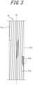
- Figure 3 illustrates the spiral belt layer.
- the spiral belt layer 51 consists of a ribbon-like first strip member 51a made with a first belt cord 51b coated with rubber, spirally wound in the circumferential direction of the tire.
- an organic fiber cord made of aromatic polyamide such as aramid can be used, alternatively, a hybrid fiber cord made from aliphatic polyamide such as nylon or the combinations of aromatic polyamide such as aramid and aliphatic polyamide such as nylon can be used.
- the hybrid cord of aliphatic and aromatic polyamide fibers may be made by twisting yarns made of aliphatic polyamide fibers with yarns made of aromatic polyamide fibers, or made of pre-composited and twisted yarns of aliphatic and aromatic polyamide fibers.
- the spiral belt layer 51 is formed by spirally winding the strip members 51a around the circumferential direction of the tire on the crown of the carcass 4 of the raw tire, with the strip members 51a deviating by a predetermined amount in the tire width direction so that no gap is created between adjacent strip members 51a.
- the inclination angle of the first belt cord 51b with respect to the circumferential direction of the tire is, for example, 5 degrees or less.
- the strip member 51a is folded back when it is wound up to the widthwise end edge 51c of the spiral belt layer 51 and begins to be wound around the outer surface as the next layer toward the other widthwise end edge 51c, thereby stacking them.
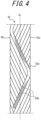
- FIG. 4 illustrates the zigzag belt layer.
- the zigzag belt layer 52 consists of a ribbon-like second strip member 52a made with a second belt cord 52b coated with rubber, spirally wound in the circumferential direction of the tire so that the following manners are repeated: extending from one tire width direction end 52c to the other tire width direction end 52c, folded back at the other tire width direction end 52c, extending from the other tire width direction end 52c to the one tire width direction end 52c, folded back at the one tire width direction end 52c, and extending again from the one tire width direction end 52c to the other tire width direction end 52c.
- an organic fiber cord made of aromatic polyamide such as aramid can be used, alternatively, a hybrid fiber cord made from aliphatic polyamide such as nylon or the combinations of aromatic polyamide such as aramid and aliphatic polyamide such as nylon can be used.
- the hybrid cord of aliphatic and aromatic polyamide fibers may be made by twisting yarns made of aliphatic polyamide fibers with yarns made of aromatic polyamide fibers, or made of pre-composited and twisted yarns of aliphatic and aromatic polyamide fibers.
- Rc is the radius at the outer surface 8 of the tire at the tire equatorial plane CL
- Wb is the distance in the tire width direction from the tire equatorial plane CL to the edge of the widest belt layer 5a that has the greatest width in the tire width direction
- the diameter difference, radius difference, between the outer surface 8 of the tire at the tire equatorial plane CL and the outer surface 8 of the tire at a position 35% of the distance Wb outward from the tire equatorial plane CL in the tire width direction is ⁇ 35
- the diameter difference between the outer surface 8 of the tire at the tire equatorial plane CL and the outer surface 8 of the tire at a position 90% of the distance Wb outward from the tire equatorial plane CL in the tire width direction is ⁇ 90
- the following inequalities are satisfied: 0 ⁇ ⁇ 35 / Rc ⁇ 0.004 and 0.015 ⁇ ⁇ 90 / Rc
- the ground contact width at very low load immediately after the touchdown can be secured and the touchdown wear can be suppressed.
- ⁇ 90/Rc ⁇ 0.025 (relatively small)
- the drag due to the diameter difference at the shoulder portion of the tire during taxiing can be reduced, thus the taxi wear can also be suppressed.
- ⁇ 90/Rc ⁇ 0.015 the belt tension at the shoulder portion can be increased to improve standing wave performance.
- the tire can be grounded around the tire equatorial plane.
- the pneumatic tire for aircraft can suppress the wear that occurs when moving through airports, while also suppressing the wear that occurs at extremely low loads at the moment the aircraft lands, and it can also improve the standing wave performance.
- the belt cords with an elastic modulus of 30 cN/dtex or greater extend at an angle of inclination of 10 degrees or less with respect to the tire equatorial plane.
- the circumferential stiffness of the belt layer is increased to ensure that the tire shape is more reliably maintained when the prescribed internal pressure is filled, and each of the above effects can be obtained more reliably.
- one or more of the belt layers can be the spiral belt layer described above.
- the elastic modulus of the belt cord is 100 cN/dtex or greater.
- the above distance Wb is 70 to 90% of the maximum tire width (the maximum width in the tire width direction of the tire in the above standard condition).
- the standing wave can further be suppressed, while by setting the maximum 90%, the weight can be reduced.
- an example tire, and a comparative example tire, having a tire size of H44.5 ⁇ 16.5 ⁇ R21 were manufactured as prototypes.
- the example and comparative example tires have a carcass consisting of five carcass plies made of nylon.
- the example and comparative example tires have a belt structure with six spiral belt layers and two zigzag belt layers, from the inner side in the tire radial direction.
- the belt cords of the zigzag belt layer were nylon cords
- the belt cords of the spiral belt layer were aramid cords.
- the distance Wb was 150 mm and Rc was 573 mm.
- Predicted wear energy was calculated by the Finite Element Method and expressed as an index with the comparative example set at 100. The smaller the index, the slower the wear rate and the better the wear performance.
- the touchdown phenomenon was simulated, and the amount of wear per touchdown at the tire equatorial plane was calculated and expressed as an index with the comparative example set at 100. The smaller the index, the better the wear performance.
- a drum test was conducted to simulate tire inputs during takeoff.
- a video camera was used to capture the side portion of the tire and measure the speed at which the standing wave occurred.
- the index is expressed as an index with the comparative example set at 100. The larger the index, the greater the speed of standing wave generation and the better the standing wave performance.
Landscapes
- Engineering & Computer Science (AREA)
- Mechanical Engineering (AREA)
- Tires In General (AREA)
Abstract
Description
- This disclosure relates to a pneumatic tire for aircraft.
- Conventionally, the pneumatic tires for aircraft have been proposed: which have a pair of bead cores, a radial carcass comprising one or more carcass plies extending toroidally between the bead cores, and a belt layer as a tread reinforcement member on the radial outer side of the radial carcass in the tread portion; the above belt layer consists of a spiral belt layer made of ribbon-like organic fibers wound in an abbreviated circumferential direction, 5 degrees or less to the tire equatorial plane, and a zigzag belt layer made of ribbon-like organic fibers wound at an angle of 2 to 45 degrees to the tire equatorial plane and folded at both ends of the belt; and the shape of the outer surface of the tread has a predetermined step-down amount δ at the intermediate land portion (PTL 1).
- PTL 1: 2012-153310
- In recent years, increased environmental awareness has led to strong demand for longer tire life also in pneumatic tires for aircraft. Improving the wear resistance performance of the tire is effective in extending tire life. Here, it is known that the wear on the pneumatic tires for aircraft occurs mainly in the following two modes: One is the wear that occurs when an aircraft moves through an airport, so-called "taxi wear", and the other is the wear caused by slippage when stationary tires contact the asphalt at high speed at the moment the aircraft lands, so-called "touchdown wear".
- The art described in
PTL 1 is effective in improving the above taxi wear. However, when the shape of the outer surface of the tread as described inPTL 1 is applied, the ground contact width under extreme loads at the moment the aircraft lands become smaller. As a result, wear in the center of the tire progressed quickly, and in some cases, performance was not sufficient with respect to touchdown wear. - It is therefore an object of this disclosure to provide a pneumatic tire for aircraft that can suppress the wear that occurs when moving through airports, while also suppressing the wear that occurs at extremely low loads at the moment the aircraft lands.
- The following is the abstract structure of this disclosure.
- (1) A pneumatic tire for aircraft comprising:
- a pair of bead portions; a carcass comprising one or more carcass plies spanning the pair of bead portions in a toroidal shape; and a belt comprising one or more belt layers disposed radially outwardly of the crown portion of the carcass; wherein
- in a reference state, in which the pneumatic tire for aircraft is mounted on an applicable rim, filled to prescribed internal pressure, deflated to 50 kPa after that, and with no load,
- Rc is the radius at the outer surface of the tire at the tire equatorial plane, and Wb is the distance in the tire width direction from the tire equatorial plane to the edge of the widest belt layer that has the greatest width in the tire width direction,
- the diameter difference between the outer surface of the tire at the tire equatorial plane and the outer surface of the tire at a
position 35% of the distance Wb outward from the tire equatorial plane in the tire width direction is δ35, - the diameter difference between the outer surface of the tire at the tire equatorial plane and the outer surface of the tire at a
position 90% of the distance Wb outward from the tire equatorial plane in the tire width direction is δ90, and the following inequalities are satisfied.
- As used herein, "applicable rim" refers to the standard rim (Design Rim) in the applicable size as described or as may be described in the future in the latest edition of the AIRCRAFT YEAR BOOK or the latest edition of the EDI (Engineering Design Information for Aircraft Tires) published by TRA (The Tire and Rim Association, Inc.) in the United States (the 2017 edition is used for numerical descriptions herein). For sizes not listed in the above standards, "applicable rim" shall mean the rim applicable to the tire.
- In addition, "prescribed internal pressure" means the air pressure, i.e., maximum air pressure, corresponding to the maximum load capacity of a single wheel in the applicable size and ply rating, as described in the above standard. For sizes not listed in the above standards, "prescribed internal pressure" shall mean the air pressure, i.e., maximum air pressure, corresponding to the maximum load capacity prescribed for each vehicle in which the tire is mounted.
- In the case where the tread section has grooves, the above outer surface of the tire shall mean the hypothetical line assuming there are no grooves.
- The elastic modulus of the belt cord herein refers to the elastic modulus of a single cord (cN/dtex) calculated from the slope "s-s curve" when a single cord is elongated by 1.5% in accordance with the standard number JIS L 1017:2002, "Test Method for Chemical Fiber Tire Cords".
- This disclosure can provide a pneumatic tire for aircraft that can suppress the wear that occurs when moving through airports, while also suppressing the wear that occurs at extremely low loads at the moment the aircraft lands.
- In the accompanying drawings:
-
FIG. 1 illustrates a cross-sectional view in the tire width direction of a pneumatic tire for aircraft according to one embodiment of this disclosure; -
FIG. 2 illustrates an enlarged view of the main part ofFIG. 1 ; -
FIG. 3 illustrates the spiral belt layer; and -
FIG. 4 illustrates the zigzag belt layer. - The following is a detailed illustrative description, with reference to the drawings, of an embodiment of a pneumatic tire for aircraft, hereinafter referred to simply as "tire", according to this disclosure.
-
Figure 1 illustrates a cross-sectional view in the tire width direction of a pneumatic tire for aircraft according to one embodiment of this disclosure.Figure 2 illustrates an enlarged view of the main part ofFigure 1. Figures 1 and2 illustrate the cross section in the tire width direction in the reference state, with thetire 1 mounted on the applicable rim R, filled to the prescribed internal pressure, and unloaded. - As illustrated in
Figure 1 , thetire 1 comprises a pair ofbead portions 2, acarcass 4 comprising one or more carcass plies spanning the pair ofbead portions 2 in a toroidal shape, and abelt 5 comprising one or more belt layers disposed radially outwardly of the crown portion of thecarcass 4. Atread portion 12 made of tread rubber is disposed on the outside of the tire radial direction of the belt, and a pair of sidewall portions are connected to the tread portion. - The
bead core 3 is buried in each of thebead portions 2. In the illustrated example, thebead core 3 consists of an annular cable bead. In the illustration, thebead core 3 is circular in cross section. The bead wire can be, for example, high-carbon steel wire. In this example, thebead filler 31 is disposed on the outer side, in the tire radial direction, of eachbead cores 3. Thebead filler 31 has an abbreviated triangular cross section, tapering in the tire width direction from the inside to the outside of the tire radial direction, but thebead filler 31 can have a variety of cross sections. For example, one or more types of any known hard rubber can be used for thebead filler 31. - The
carcass 4 consists of one or more, e.g., 4 to 7, carcass plies. In this example, thecarcass 4 is a radial carcass. - The
carcass 4 consists of one or more overlapping carcass plies, for example 4 to 7 carcass plies are overlapped, and their ends are rolled up and secured around thebead core 3 from the inside to the outside in the tire radial direction. In this embodiment oftire 1, seven layers of carcass plies made of nylon cords are stacked on top of each other. - As illustrated in
Figures 1 and2 , in this example, thebelt 5 consists of 8belt layers 5a-5h. In this example, thebelt 5 has sixspiral belt layers 5a-5f and twozigzag belt layers - In the illustrated example, the width of the belt layers in the tire width direction is, in order from largest to smallest width, 5a, 5b, 5c, 5d, 5g=5h, 5e, and 5f. In the illustration, the
belt layer 5a is the widest belt layer with the greatest width in the tire width direction. The distance in the tire width direction from the tire equatorial plane CL to the edge of thewidest belt layer 5a is Wb. Note that, the width of the belt layers is not limited to the above examples, and any of the belt layers may have the maximum width in the tire width direction, and the relationship between the widths of the belt layers other than the widest belt layer in the tire width direction is not particularly limited. - Here, the spiral belt layer is explained.
Figure 3 illustrates the spiral belt layer. As illustrated inFigure 3 , thespiral belt layer 51 consists of a ribbon-likefirst strip member 51a made with afirst belt cord 51b coated with rubber, spirally wound in the circumferential direction of the tire. - As the
first belt cord 51b, an organic fiber cord made of aromatic polyamide such as aramid can be used, alternatively, a hybrid fiber cord made from aliphatic polyamide such as nylon or the combinations of aromatic polyamide such as aramid and aliphatic polyamide such as nylon can be used. - The hybrid cord of aliphatic and aromatic polyamide fibers may be made by twisting yarns made of aliphatic polyamide fibers with yarns made of aromatic polyamide fibers, or made of pre-composited and twisted yarns of aliphatic and aromatic polyamide fibers.
- The
spiral belt layer 51 is formed by spirally winding thestrip members 51a around the circumferential direction of the tire on the crown of thecarcass 4 of the raw tire, with thestrip members 51a deviating by a predetermined amount in the tire width direction so that no gap is created betweenadjacent strip members 51a. The inclination angle of thefirst belt cord 51b with respect to the circumferential direction of the tire is, for example, 5 degrees or less. - When the
spiral belt layer 51 consists of multiple layers, thestrip member 51a is folded back when it is wound up to thewidthwise end edge 51c of thespiral belt layer 51 and begins to be wound around the outer surface as the next layer toward the otherwidthwise end edge 51c, thereby stacking them. - Next, the zigzag belt layer is explained.
Figure 4 illustrates the zigzag belt layer. Thezigzag belt layer 52 consists of a ribbon-likesecond strip member 52a made with asecond belt cord 52b coated with rubber, spirally wound in the circumferential direction of the tire so that the following manners are repeated: extending from one tirewidth direction end 52c to the other tirewidth direction end 52c, folded back at the other tirewidth direction end 52c, extending from the other tirewidth direction end 52c to the one tirewidth direction end 52c, folded back at the one tirewidth direction end 52c, and extending again from the one tirewidth direction end 52c to the other tirewidth direction end 52c. - As the
second belt cord 52b, an organic fiber cord made of aromatic polyamide such as aramid can be used, alternatively, a hybrid fiber cord made from aliphatic polyamide such as nylon or the combinations of aromatic polyamide such as aramid and aliphatic polyamide such as nylon can be used. - The hybrid cord of aliphatic and aromatic polyamide fibers may be made by twisting yarns made of aliphatic polyamide fibers with yarns made of aromatic polyamide fibers, or made of pre-composited and twisted yarns of aliphatic and aromatic polyamide fibers.
- Return to
Figure 1 and2 , in the tire of this embodiment, in a reference state, Rc is the radius at theouter surface 8 of the tire at the tire equatorial plane CL, and Wb is the distance in the tire width direction from the tire equatorial plane CL to the edge of thewidest belt layer 5a that has the greatest width in the tire width direction, the diameter difference, radius difference, between theouter surface 8 of the tire at the tire equatorial plane CL and theouter surface 8 of the tire at aposition 35% of the distance Wb outward from the tire equatorial plane CL in the tire width direction is δ35, the diameter difference between theouter surface 8 of the tire at the tire equatorial plane CL and theouter surface 8 of the tire at aposition 90% of the distance Wb outward from the tire equatorial plane CL in the tire width direction is δ90, and the following inequalities are satisfied:
- The following is an explanation of the effects of this embodiment of pneumatic tire for aircraft.
- According to the pneumatic tire for aircraft of this embodiment, first, by setting δ35/Rc ≤ 0.004 (relatively small), the ground contact width at very low load immediately after the touchdown can be secured and the touchdown wear can be suppressed. Also, by setting δ90/Rc ≤ 0.025 (relatively small), the drag due to the diameter difference at the shoulder portion of the tire during taxiing can be reduced, thus the taxi wear can also be suppressed. Furthermore, by setting δ90/Rc ≥ 0.015, the belt tension at the shoulder portion can be increased to improve standing wave performance. In addition, by setting 0 ≤ δ35/Rc, the tire can be grounded around the tire equatorial plane.
- As described above, the pneumatic tire for aircraft according to this embodiment can suppress the wear that occurs when moving through airports, while also suppressing the wear that occurs at extremely low loads at the moment the aircraft lands, and it can also improve the standing wave performance.
- For the same reasons as above, in the reference state,
it is more preferable to satisfy the following inequality:
- Further, in the reference state,
it is preferable to further satisfy the following inequality:
- By setting (δ90-δ35)/Rc ≤ 0.024, the taxi wear can further be suppressed, while by setting 0.014 ≤ (δ90-δ35)/Rc, the standing wave performance can be further improved.
- For the same reasons, in the reference state,
it is further preferable to satisfy the following inequality:
- Here, it is preferable that in one or more of the belt layers, the belt cords with an elastic modulus of 30 cN/dtex or greater extend at an angle of inclination of 10 degrees or less with respect to the tire equatorial plane. This is because the circumferential stiffness of the belt layer is increased to ensure that the tire shape is more reliably maintained when the prescribed internal pressure is filled, and each of the above effects can be obtained more reliably. For example, one or more of the belt layers can be the spiral belt layer described above. In this case, in order to achieve the above elastic modulus in the belt layer, it is preferable to use a hybrid cord of nylon and aramid, although not particularly limited.
- For the same reason, in the above case, it is further preferred that the elastic modulus of the belt cord is 100 cN/dtex or greater. In this case, in order to achieve the above elastic modulus in the belt layer, it is preferable to use a aramid cord, although not particularly limited.
- Here, it is preferable that the above distance Wb is 70 to 90% of the maximum tire width (the maximum width in the tire width direction of the tire in the above standard condition). By setting the minimum 70%, the standing wave can further be suppressed, while by setting the maximum 90%, the weight can be reduced.
- In order to confirm the effect of this disclosure, an example tire, and a comparative example tire, having a tire size of H44.5×16.5×R21 were manufactured as prototypes. The example and comparative example tires have a carcass consisting of five carcass plies made of nylon. The example and comparative example tires have a belt structure with six spiral belt layers and two zigzag belt layers, from the inner side in the tire radial direction. In the example and comparative example tires, the belt cords of the zigzag belt layer were nylon cords, and the belt cords of the spiral belt layer were aramid cords. In the example and comparative example tires, the distance Wb was 150 mm and Rc was 573 mm. For the comparative example tire, δ35/Rc = 0.0080, δ90/Rc = 0.031, and (690-635)/Rc = 0.023. For the example tire, δ35/Rc = 0.0016, δ90/Rc = 0.021, and (690-635)/Rc = 0.020.
- The following tests were conducted on the example and comparative example tires:
- Predicted wear energy was calculated by the Finite Element Method and expressed as an index with the comparative example set at 100. The smaller the index, the slower the wear rate and the better the wear performance.
- The touchdown phenomenon was simulated, and the amount of wear per touchdown at the tire equatorial plane was calculated and expressed as an index with the comparative example set at 100. The smaller the index, the better the wear performance.
- A drum test was conducted to simulate tire inputs during takeoff. A video camera was used to capture the side portion of the tire and measure the speed at which the standing wave occurred. The index is expressed as an index with the comparative example set at 100. The larger the index, the greater the speed of standing wave generation and the better the standing wave performance.
- The evaluation results for the example were as follows. Wear resistance performance during turning: 94, Touchdown wear resistance performance: 78, Standing wave performance: 100.
-
- 1
- pneumatic tire for aircraft
- 2
- bead portion
- 3
- bead core
- 4
- carcass
- 5
- belt
- 8
- outer surface of the tire
- 12
- tread portion
- R
- applicable rim
Claims (4)
- A pneumatic tire for aircraft comprising:a pair of bead portions;a carcass comprising one or more carcass plies spanning the pair of bead portions in a toroidal shape; anda belt comprising one or more belt layers disposed radially outwardly of the crown portion of the carcass; whereinin a reference state, in which the pneumatic tire for aircraft is mounted on an applicable rim, filled to prescribed internal pressure, deflated to 50 kPa after that, and with no load,Rc is the radius at the outer surface of the tire at the tire equatorial plane, and Wb is the distance in the tire width direction from the tire equatorial plane to the edge of the widest belt layer that has the greatest width in the tire width direction,the diameter difference between the outer surface of the tire at the tire equatorial plane and the outer surface of the tire at a position 35% of the distance Wb outward from the tire equatorial plane in the tire width direction is δ35,the diameter difference between the outer surface of the tire at the tire equatorial plane and the outer surface of the tire at a position 90% of the distance Wb outward from the tire equatorial plane in the tire width direction is δ90, andthe following inequalities are satisfied.

- The pneumatic tire for aircraft according to claim 1, wherein
in the reference state, the following inequality is further satisfied.
- The pneumatic tire for aircraft according to claim 1 or 2, wherein in one or more of the belt layers, belt cords with an elastic modulus of 30 cN/dtex or greater extend at an angle of inclination of 10 degrees or less with respect to the tire equatorial plane.
- The pneumatic tire for aircraft according to claim 3, wherein the elastic modulus of the belt cord is 100 cN/dtex or greater.
Applications Claiming Priority (2)
| Application Number | Priority Date | Filing Date | Title |
|---|---|---|---|
| JP2020192349A JP7386779B2 (en) | 2020-11-19 | 2020-11-19 | Aircraft pneumatic tires |
| PCT/JP2021/017280 WO2022107357A1 (en) | 2020-11-19 | 2021-04-30 | Pneumatic tire for aircraft |
Publications (3)
| Publication Number | Publication Date |
|---|---|
| EP4249289A1 true EP4249289A1 (en) | 2023-09-27 |
| EP4249289A4 EP4249289A4 (en) | 2024-04-17 |
| EP4249289B1 EP4249289B1 (en) | 2025-08-20 |
Family
ID=81753270
Family Applications (1)
| Application Number | Title | Priority Date | Filing Date |
|---|---|---|---|
| EP21894234.0A Active EP4249289B1 (en) | 2020-11-19 | 2021-04-30 | Pneumatic tire for aircraft |
Country Status (5)
| Country | Link |
|---|---|
| US (1) | US20230391141A1 (en) |
| EP (1) | EP4249289B1 (en) |
| JP (1) | JP7386779B2 (en) |
| CN (1) | CN116490383B (en) |
| WO (1) | WO2022107357A1 (en) |
Family Cites Families (16)
| Publication number | Priority date | Publication date | Assignee | Title |
|---|---|---|---|---|
| FR2187559A1 (en) | 1972-06-01 | 1974-01-18 | Kleber Colombes | Wide tread aircraft tyre - with mixed ply and cylindrical tread over periph-eral belt |
| FR2499474A1 (en) * | 1981-02-12 | 1982-08-13 | Michelin & Cie | TIRE, IN PARTICULAR FOR AIRCRAFT, WITH TEXTILE CABLES TOP FRAME, AND METHOD FOR MANUFACTURING THE SAME |
| JPH07228105A (en) * | 1993-12-24 | 1995-08-29 | Sumitomo Rubber Ind Ltd | Pneumatic tire |
| KR100631393B1 (en) * | 2004-07-14 | 2006-10-04 | 금호타이어 주식회사 | Tire for aircraft |
| WO2006035940A1 (en) | 2004-09-30 | 2006-04-06 | Bridgestone Corporation | Pneumatic radial tire |
| JP4618637B2 (en) * | 2005-01-18 | 2011-01-26 | 株式会社ブリヂストン | Pneumatic radial tire for aircraft |
| JP4627664B2 (en) | 2005-02-15 | 2011-02-09 | 株式会社ブリヂストン | Pneumatic radial tire |
| JP4953632B2 (en) * | 2006-01-04 | 2012-06-13 | 株式会社ブリヂストン | Aircraft radial tire |
| CN102405143B (en) * | 2009-03-03 | 2014-02-19 | 株式会社普利司通 | Radial tire for aircraft |
| JP2012254661A (en) * | 2011-06-07 | 2012-12-27 | Bridgestone Corp | Aircraft radial tire |
| JP5977968B2 (en) * | 2012-03-14 | 2016-08-24 | 株式会社ブリヂストン | Pneumatic tire |
| KR101730941B1 (en) * | 2012-10-10 | 2017-04-27 | 요코하마 고무 가부시키가이샤 | Pneumatic tire |
| JP6055351B2 (en) * | 2013-03-27 | 2016-12-27 | 住友ゴム工業株式会社 | Radial tires for passenger cars |
| JP2017071276A (en) * | 2015-10-06 | 2017-04-13 | 横浜ゴム株式会社 | Pneumatic tire |
| JP6847634B2 (en) * | 2016-11-14 | 2021-03-24 | 株式会社ブリヂストン | Radial tires for aircraft |
| JP6701060B2 (en) * | 2016-11-30 | 2020-05-27 | 株式会社ブリヂストン | Rubber-cord composite, tire reinforcing member, and tire using the same |
-
2020
- 2020-11-19 JP JP2020192349A patent/JP7386779B2/en active Active
-
2021
- 2021-04-30 WO PCT/JP2021/017280 patent/WO2022107357A1/en not_active Ceased
- 2021-04-30 US US18/250,749 patent/US20230391141A1/en not_active Abandoned
- 2021-04-30 CN CN202180075587.0A patent/CN116490383B/en active Active
- 2021-04-30 EP EP21894234.0A patent/EP4249289B1/en active Active
Also Published As
| Publication number | Publication date |
|---|---|
| CN116490383B (en) | 2025-09-09 |
| WO2022107357A1 (en) | 2022-05-27 |
| EP4249289B1 (en) | 2025-08-20 |
| JP2022081053A (en) | 2022-05-31 |
| CN116490383A (en) | 2023-07-25 |
| EP4249289A4 (en) | 2024-04-17 |
| US20230391141A1 (en) | 2023-12-07 |
| JP7386779B2 (en) | 2023-11-27 |
Similar Documents
| Publication | Publication Date | Title |
|---|---|---|
| US9346321B2 (en) | Reduced weight aircraft tire | |
| JP2008114841A (en) | Reduced weight aircraft tire | |
| US8578988B2 (en) | Reduced weight aircraft tire | |
| US20160263944A1 (en) | Reduced weight aircraft tire | |
| EP3838619A1 (en) | Pneumatic tire | |
| JP2017222209A (en) | Pneumatic tire | |
| CN107791749B (en) | Aircraft tire with reduced weight | |
| JP4856374B2 (en) | Aircraft pneumatic tire | |
| EP2444259B1 (en) | Reduced weight tire | |
| US8967213B2 (en) | Aircraft tire | |
| EP4249289B1 (en) | Pneumatic tire for aircraft | |
| JP7691224B2 (en) | Lighter aircraft tires | |
| US20120312440A1 (en) | Reduced weight aircraft tire | |
| EP4249287A1 (en) | Pneumatic tire for aircraft | |
| EP3988329B1 (en) | Tire | |
| EP0447200B1 (en) | High speed heavy duty tyre | |
| US20210146726A1 (en) | Reduced weight aircraft tire | |
| JP2007161003A (en) | Radial tire for aircraft | |
| GB2507199A (en) | Pneumatic tyre |
Legal Events
| Date | Code | Title | Description |
|---|---|---|---|
| STAA | Information on the status of an ep patent application or granted ep patent |
Free format text: STATUS: THE INTERNATIONAL PUBLICATION HAS BEEN MADE |
|
| PUAI | Public reference made under article 153(3) epc to a published international application that has entered the european phase |
Free format text: ORIGINAL CODE: 0009012 |
|
| STAA | Information on the status of an ep patent application or granted ep patent |
Free format text: STATUS: REQUEST FOR EXAMINATION WAS MADE |
|
| 17P | Request for examination filed |
Effective date: 20230328 |
|
| AK | Designated contracting states |
Kind code of ref document: A1 Designated state(s): AL AT BE BG CH CY CZ DE DK EE ES FI FR GB GR HR HU IE IS IT LI LT LU LV MC MK MT NL NO PL PT RO RS SE SI SK SM TR |
|
| DAV | Request for validation of the european patent (deleted) | ||
| DAX | Request for extension of the european patent (deleted) | ||
| A4 | Supplementary search report drawn up and despatched |
Effective date: 20240314 |
|
| RIC1 | Information provided on ipc code assigned before grant |
Ipc: B60C 9/22 20060101ALI20240308BHEP Ipc: B60C 9/18 20060101ALI20240308BHEP Ipc: B60C 9/08 20060101ALI20240308BHEP Ipc: B60C 9/26 20060101ALI20240308BHEP Ipc: B60C 9/00 20060101ALI20240308BHEP Ipc: B60C 11/01 20060101ALI20240308BHEP Ipc: B60C 11/00 20060101AFI20240308BHEP |
|
| GRAP | Despatch of communication of intention to grant a patent |
Free format text: ORIGINAL CODE: EPIDOSNIGR1 |
|
| STAA | Information on the status of an ep patent application or granted ep patent |
Free format text: STATUS: GRANT OF PATENT IS INTENDED |
|
| RIC1 | Information provided on ipc code assigned before grant |
Ipc: B60C 9/22 20060101ALI20250207BHEP Ipc: B60C 9/18 20060101ALI20250207BHEP Ipc: B60C 9/08 20060101ALI20250207BHEP Ipc: B60C 9/26 20060101ALI20250207BHEP Ipc: B60C 9/00 20060101ALI20250207BHEP Ipc: B60C 11/01 20060101ALI20250207BHEP Ipc: B60C 11/00 20060101AFI20250207BHEP |
|
| INTG | Intention to grant announced |
Effective date: 20250317 |
|
| P01 | Opt-out of the competence of the unified patent court (upc) registered |
Free format text: CASE NUMBER: APP_16557/2025 Effective date: 20250404 |
|
| GRAS | Grant fee paid |
Free format text: ORIGINAL CODE: EPIDOSNIGR3 |
|
| GRAA | (expected) grant |
Free format text: ORIGINAL CODE: 0009210 |
|
| STAA | Information on the status of an ep patent application or granted ep patent |
Free format text: STATUS: THE PATENT HAS BEEN GRANTED |
|
| AK | Designated contracting states |
Kind code of ref document: B1 Designated state(s): AL AT BE BG CH CY CZ DE DK EE ES FI FR GB GR HR HU IE IS IT LI LT LU LV MC MK MT NL NO PL PT RO RS SE SI SK SM TR |
|
| REG | Reference to a national code |
Ref country code: GB Ref legal event code: FG4D |
|
| REG | Reference to a national code |
Ref country code: CH Ref legal event code: EP |
|
| REG | Reference to a national code |
Ref country code: IE Ref legal event code: FG4D |
|
| REG | Reference to a national code |
Ref country code: DE Ref legal event code: R096 Ref document number: 602021036888 Country of ref document: DE |
|
| REG | Reference to a national code |
Ref country code: NL Ref legal event code: MP Effective date: 20250820 |
|
| PG25 | Lapsed in a contracting state [announced via postgrant information from national office to epo] |
Ref country code: IS Free format text: LAPSE BECAUSE OF FAILURE TO SUBMIT A TRANSLATION OF THE DESCRIPTION OR TO PAY THE FEE WITHIN THE PRESCRIBED TIME-LIMIT Effective date: 20251220 |
|
| PG25 | Lapsed in a contracting state [announced via postgrant information from national office to epo] |
Ref country code: NO Free format text: LAPSE BECAUSE OF FAILURE TO SUBMIT A TRANSLATION OF THE DESCRIPTION OR TO PAY THE FEE WITHIN THE PRESCRIBED TIME-LIMIT Effective date: 20251120 |
|
| REG | Reference to a national code |
Ref country code: LT Ref legal event code: MG9D |
|
| PG25 | Lapsed in a contracting state [announced via postgrant information from national office to epo] |
Ref country code: PT Free format text: LAPSE BECAUSE OF FAILURE TO SUBMIT A TRANSLATION OF THE DESCRIPTION OR TO PAY THE FEE WITHIN THE PRESCRIBED TIME-LIMIT Effective date: 20251222 |
|
| PG25 | Lapsed in a contracting state [announced via postgrant information from national office to epo] |
Ref country code: FI Free format text: LAPSE BECAUSE OF FAILURE TO SUBMIT A TRANSLATION OF THE DESCRIPTION OR TO PAY THE FEE WITHIN THE PRESCRIBED TIME-LIMIT Effective date: 20250820 |
|
| PG25 | Lapsed in a contracting state [announced via postgrant information from national office to epo] |
Ref country code: HR Free format text: LAPSE BECAUSE OF FAILURE TO SUBMIT A TRANSLATION OF THE DESCRIPTION OR TO PAY THE FEE WITHIN THE PRESCRIBED TIME-LIMIT Effective date: 20250820 Ref country code: NL Free format text: LAPSE BECAUSE OF FAILURE TO SUBMIT A TRANSLATION OF THE DESCRIPTION OR TO PAY THE FEE WITHIN THE PRESCRIBED TIME-LIMIT Effective date: 20250820 |
|
| PG25 | Lapsed in a contracting state [announced via postgrant information from national office to epo] |
Ref country code: GR Free format text: LAPSE BECAUSE OF FAILURE TO SUBMIT A TRANSLATION OF THE DESCRIPTION OR TO PAY THE FEE WITHIN THE PRESCRIBED TIME-LIMIT Effective date: 20251121 |
|
| PG25 | Lapsed in a contracting state [announced via postgrant information from national office to epo] |
Ref country code: SE Free format text: LAPSE BECAUSE OF FAILURE TO SUBMIT A TRANSLATION OF THE DESCRIPTION OR TO PAY THE FEE WITHIN THE PRESCRIBED TIME-LIMIT Effective date: 20250820 |
|
| PG25 | Lapsed in a contracting state [announced via postgrant information from national office to epo] |
Ref country code: LV Free format text: LAPSE BECAUSE OF FAILURE TO SUBMIT A TRANSLATION OF THE DESCRIPTION OR TO PAY THE FEE WITHIN THE PRESCRIBED TIME-LIMIT Effective date: 20250820 |
|
| PG25 | Lapsed in a contracting state [announced via postgrant information from national office to epo] |
Ref country code: PL Free format text: LAPSE BECAUSE OF FAILURE TO SUBMIT A TRANSLATION OF THE DESCRIPTION OR TO PAY THE FEE WITHIN THE PRESCRIBED TIME-LIMIT Effective date: 20250820 Ref country code: BG Free format text: LAPSE BECAUSE OF FAILURE TO SUBMIT A TRANSLATION OF THE DESCRIPTION OR TO PAY THE FEE WITHIN THE PRESCRIBED TIME-LIMIT Effective date: 20250820 |
|
| PG25 | Lapsed in a contracting state [announced via postgrant information from national office to epo] |
Ref country code: RS Free format text: LAPSE BECAUSE OF FAILURE TO SUBMIT A TRANSLATION OF THE DESCRIPTION OR TO PAY THE FEE WITHIN THE PRESCRIBED TIME-LIMIT Effective date: 20251120 |
|
| PG25 | Lapsed in a contracting state [announced via postgrant information from national office to epo] |
Ref country code: ES Free format text: LAPSE BECAUSE OF FAILURE TO SUBMIT A TRANSLATION OF THE DESCRIPTION OR TO PAY THE FEE WITHIN THE PRESCRIBED TIME-LIMIT Effective date: 20250820 |
|
| REG | Reference to a national code |
Ref country code: AT Ref legal event code: MK05 Ref document number: 1826950 Country of ref document: AT Kind code of ref document: T Effective date: 20250820 |
|
| PG25 | Lapsed in a contracting state [announced via postgrant information from national office to epo] |
Ref country code: SM Free format text: LAPSE BECAUSE OF FAILURE TO SUBMIT A TRANSLATION OF THE DESCRIPTION OR TO PAY THE FEE WITHIN THE PRESCRIBED TIME-LIMIT Effective date: 20250820 |
|
| PG25 | Lapsed in a contracting state [announced via postgrant information from national office to epo] |
Ref country code: DK Free format text: LAPSE BECAUSE OF FAILURE TO SUBMIT A TRANSLATION OF THE DESCRIPTION OR TO PAY THE FEE WITHIN THE PRESCRIBED TIME-LIMIT Effective date: 20250820 |
|
| PG25 | Lapsed in a contracting state [announced via postgrant information from national office to epo] |
Ref country code: AT Free format text: LAPSE BECAUSE OF FAILURE TO SUBMIT A TRANSLATION OF THE DESCRIPTION OR TO PAY THE FEE WITHIN THE PRESCRIBED TIME-LIMIT Effective date: 20250820 |
|
| PG25 | Lapsed in a contracting state [announced via postgrant information from national office to epo] |
Ref country code: IT Free format text: LAPSE BECAUSE OF FAILURE TO SUBMIT A TRANSLATION OF THE DESCRIPTION OR TO PAY THE FEE WITHIN THE PRESCRIBED TIME-LIMIT Effective date: 20250820 |
|
| PG25 | Lapsed in a contracting state [announced via postgrant information from national office to epo] |
Ref country code: CZ Free format text: LAPSE BECAUSE OF FAILURE TO SUBMIT A TRANSLATION OF THE DESCRIPTION OR TO PAY THE FEE WITHIN THE PRESCRIBED TIME-LIMIT Effective date: 20250820 |
|
| PG25 | Lapsed in a contracting state [announced via postgrant information from national office to epo] |
Ref country code: SK Free format text: LAPSE BECAUSE OF FAILURE TO SUBMIT A TRANSLATION OF THE DESCRIPTION OR TO PAY THE FEE WITHIN THE PRESCRIBED TIME-LIMIT Effective date: 20250820 Ref country code: EE Free format text: LAPSE BECAUSE OF FAILURE TO SUBMIT A TRANSLATION OF THE DESCRIPTION OR TO PAY THE FEE WITHIN THE PRESCRIBED TIME-LIMIT Effective date: 20250820 |