EP4249275A1 - Printer - Google Patents
Printer Download PDFInfo
- Publication number
- EP4249275A1 EP4249275A1 EP23162858.7A EP23162858A EP4249275A1 EP 4249275 A1 EP4249275 A1 EP 4249275A1 EP 23162858 A EP23162858 A EP 23162858A EP 4249275 A1 EP4249275 A1 EP 4249275A1
- Authority
- EP
- European Patent Office
- Prior art keywords
- cover
- opening
- connector
- interface
- printer
- Prior art date
- Legal status (The legal status is an assumption and is not a legal conclusion. Google has not performed a legal analysis and makes no representation as to the accuracy of the status listed.)
- Granted
Links
Images




Classifications
-
- H—ELECTRICITY
- H01—ELECTRIC ELEMENTS
- H01R—ELECTRICALLY-CONDUCTIVE CONNECTIONS; STRUCTURAL ASSOCIATIONS OF A PLURALITY OF MUTUALLY-INSULATED ELECTRICAL CONNECTING ELEMENTS; COUPLING DEVICES; CURRENT COLLECTORS
- H01R13/00—Details of coupling devices of the kinds covered by groups H01R12/70 or H01R24/00 - H01R33/00
- H01R13/46—Bases; Cases
- H01R13/52—Dustproof, splashproof, drip-proof, waterproof, or flameproof cases
-
- H—ELECTRICITY
- H04—ELECTRIC COMMUNICATION TECHNIQUE
- H04N—PICTORIAL COMMUNICATION, e.g. TELEVISION
- H04N1/00—Scanning, transmission or reproduction of documents or the like, e.g. facsimile transmission; Details thereof
- H04N1/00885—Power supply means, e.g. arrangements for the control of power supply to the apparatus or components thereof
- H04N1/00907—Details of supply connection, e.g. arrangement of power cables
-
- B—PERFORMING OPERATIONS; TRANSPORTING
- B41—PRINTING; LINING MACHINES; TYPEWRITERS; STAMPS
- B41J—TYPEWRITERS; SELECTIVE PRINTING MECHANISMS, i.e. MECHANISMS PRINTING OTHERWISE THAN FROM A FORME; CORRECTION OF TYPOGRAPHICAL ERRORS
- B41J29/00—Details of, or accessories for, typewriters or selective printing mechanisms not otherwise provided for
- B41J29/02—Framework
-
- B—PERFORMING OPERATIONS; TRANSPORTING
- B41—PRINTING; LINING MACHINES; TYPEWRITERS; STAMPS
- B41J—TYPEWRITERS; SELECTIVE PRINTING MECHANISMS, i.e. MECHANISMS PRINTING OTHERWISE THAN FROM A FORME; CORRECTION OF TYPOGRAPHICAL ERRORS
- B41J29/00—Details of, or accessories for, typewriters or selective printing mechanisms not otherwise provided for
- B41J29/12—Guards, shields or dust excluders
-
- G—PHYSICS
- G03—PHOTOGRAPHY; CINEMATOGRAPHY; ANALOGOUS TECHNIQUES USING WAVES OTHER THAN OPTICAL WAVES; ELECTROGRAPHY; HOLOGRAPHY
- G03G—ELECTROGRAPHY; ELECTROPHOTOGRAPHY; MAGNETOGRAPHY
- G03G15/00—Apparatus for electrographic processes using a charge pattern
- G03G15/80—Details relating to power supplies, circuits boards, electrical connections
-
- H—ELECTRICITY
- H04—ELECTRIC COMMUNICATION TECHNIQUE
- H04N—PICTORIAL COMMUNICATION, e.g. TELEVISION
- H04N1/00—Scanning, transmission or reproduction of documents or the like, e.g. facsimile transmission; Details thereof
- H04N1/00519—Constructional details not otherwise provided for, e.g. housings, covers
- H04N1/00538—Modular devices, i.e. allowing combinations of separate components, removal or replacement of components
-
- H—ELECTRICITY
- H04—ELECTRIC COMMUNICATION TECHNIQUE
- H04N—PICTORIAL COMMUNICATION, e.g. TELEVISION
- H04N1/00—Scanning, transmission or reproduction of documents or the like, e.g. facsimile transmission; Details thereof
- H04N1/00519—Constructional details not otherwise provided for, e.g. housings, covers
- H04N1/00557—Connection or assembly of components or elements
-
- H—ELECTRICITY
- H04—ELECTRIC COMMUNICATION TECHNIQUE
- H04N—PICTORIAL COMMUNICATION, e.g. TELEVISION
- H04N1/00—Scanning, transmission or reproduction of documents or the like, e.g. facsimile transmission; Details thereof
- H04N1/00519—Constructional details not otherwise provided for, e.g. housings, covers
- H04N1/00559—Mounting or support of components or elements
-
- H—ELECTRICITY
- H05—ELECTRIC TECHNIQUES NOT OTHERWISE PROVIDED FOR
- H05K—PRINTED CIRCUITS; CASINGS OR CONSTRUCTIONAL DETAILS OF ELECTRIC APPARATUS; MANUFACTURE OF ASSEMBLAGES OF ELECTRICAL COMPONENTS
- H05K5/00—Casings, cabinets or drawers for electric apparatus
- H05K5/06—Hermetically-sealed casings
-
- H—ELECTRICITY
- H01—ELECTRIC ELEMENTS
- H01R—ELECTRICALLY-CONDUCTIVE CONNECTIONS; STRUCTURAL ASSOCIATIONS OF A PLURALITY OF MUTUALLY-INSULATED ELECTRICAL CONNECTING ELEMENTS; COUPLING DEVICES; CURRENT COLLECTORS
- H01R13/00—Details of coupling devices of the kinds covered by groups H01R12/70 or H01R24/00 - H01R33/00
- H01R13/46—Bases; Cases
- H01R13/52—Dustproof, splashproof, drip-proof, waterproof, or flameproof cases
- H01R13/5213—Covers
Definitions
- the present invention relates to a printer.
- printer including: a board including a connector unit that includes at least a power supply connector into which a power cable is to be removably inserted; and a housing including: a housing main body that accommodates the board and includes a cable connection groove through which the power cable is inserted in an inserting and removing direction of the power cable; and a connector cover configured to cover the cable connection groove, wherein the connector cover includes: a cover main body including a power supply opening portion passing through the cover main body in the inserting and removing direction, and a first interface opening portion passing through the cover main body in the inserting and removing direction; and a first opening cover portion configured to cover at least a part of the first interface opening portion, wherein the first opening cover portion includes a first coupling portion configured to couple the first opening cover portion and the cover main body to each other.
- the connector unit further includes an interface connector into which an interface cable is removably inserted in the inserting and removing direction
- the cover main body of the connector cover further includes a second interface opening portion passing through the cover main body in the inserting and removing direction
- a second opening cover portion configured to cover the second interface opening portion formed in the connector cover is removed during manufacture, and, through the second interface opening portion, the interface connector is exposed when seen from the inserting and removing direction.
- the connector unit is arrayed on one side of the board close to the cover main body and along the one side.
- the power supply connector is exposed through the power supply opening portion when seen from the inserting and removing direction.
- the first coupling portion includes a thin portion having a smaller thickness in the inserting and removing direction than other portions of the first coupling portion.
- the first coupling portion is split from the thin portion when an external force is applied to the first opening cover portion.
- no cover is provided for covering the power supply opening portion.
- the first opening cover portion includes a stopper that is engaged with an edge portion of the board when an external force is applied to the first opening cover portion to an insertion side in the inserting and removing direction.
- the stopper and the first coupling portion are formed on both sides of the first opening cover portion across a center axis passing a center of the first opening cover portion.
- the first opening cover portion includes two or more first coupling portions.
- the first opening cover portion further includes a second coupling portion configured to couple the first opening cover portion and the cover main body to each other, and the first coupling portion and the second coupling portion are formed on both sides of the first opening cover portion across the center axis passing the center of the first opening cover portion.
- the first opening cover portion is formed so as to be larger than the first interface opening portion, and formed so as to overlap the entire first interface opening portion when seen from the inserting and removing direction.
- FIG. 1 is a perspective view for illustrating a printer 1 according to an embodiment of the present invention.
- FIG. 2 is a side view for illustrating the printer 1 when seen from a rear side RR thereof.
- FIG. 3 is a sectional side view for illustrating an internal configuration of the printer 1 taken along the line A-A of FIG. 1 .
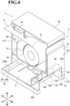
- FIG. 4 is a sectional perspective view for illustrating the internal configuration of the entire printer 1 taken along the line A-A of FIG. 1 at portions other than a lower cover 22 and a board 3 of the printer 1.
- the printer 1 is a thermal printer that performs printing on a recording sheet P through heat.
- the printer 1 performs printing on the recording sheet P.
- the recording sheet P in this embodiment is, for example, a heat sensitive roll sheet to be used for a thermal printing system.
- the recording sheet P is wound around a tubular core material R1 (see FIG. 3 ), thereby forming a roll sheet R.
- the roll sheet R may have a configuration without the core material R1.
- the printer 1 includes a casing (housing) 2, the board 3, and a printing unit 4.
- the printer 1 is placed on a placement surface G.
- a direction perpendicular to the placement surface G is referred to as an up-and-down direction.
- An upper side in the up-and-down direction is referred to as an upper side UP, and a side opposite to the upper side UP is referred to as a lower side DW.
- a direction in which the recording sheet P is to be conveyed, which is orthogonal to the up-and-down direction is referred to as a front-and-rear direction.
- a front side FR One side in the front-and-rear direction on which the recording sheet P is to be delivered from the printer 1 is referred to as a front side FR, and a side opposite to the front side FR is referred to as a rear side RR. Further, a direction orthogonal to the up-and-down direction and the front-and-rear direction is referred to as a right-and-left direction.
- One side in the right-and-left direction is referred to as a left side LH, and a side opposite to the left side LH is referred to as a right side RH.
- the casing (housing) 2 is formed into a box shape.
- the casing 2 accommodates, in an accommodation space thereof, the board 3 and the printing unit 4. It is preferred that the casing 2 define the accommodation space in a hermetic manner so as to protect the board 3 and the printing unit 4 from, for example, moisture and dust.
- the casing 2 includes an upper cover 20, a housing main body 21, and the lower cover 22.
- the upper cover 20 opens and closes an upper-end opening portion 21a of the housing main body 21.
- the upper cover 20 is formed into a box shape opened to the lower side DW, and has the same shape as that of the housing main body 21 in plan view.
- the upper cover 20 is superposed on the housing main body 21 from the upper side UP, and closes the upper-end opening portion 21a of the housing main body 21.
- a delivery slot 23 is defined between the housing main body 21 and the upper cover 20.
- the delivery slot 23 allows communication between an inside and an outside of the casing 2, and has a slit shape extending in the right-and-left direction.
- the recording sheet P having been subjected to printing by the printing unit 4 is delivered toward the front side FR. Meanwhile, in an opening position, the upper cover 20 retreats from an upper side of the housing main body 21, and opens the upper-end opening portion 21a of the housing main body 21.
- the housing main body 21 includes the upper-end opening portion 21a on the upper side UP, and a lower-end opening portion 21b on the lower side DW.
- the housing main body 21 is formed into a bottomless box shape including a front wall 211 and a rear wall 212 in the front-and-rear direction and including a left wall 213 and a right wall 214 in the right-and-left direction.
- the front wall 211, the rear wall 212, the left wall 213, and the right wall 214 are each a part of an outer wall of the housing main body 21.
- the front wall 211 is provided on the front side FR of the housing main body 21.
- the rear wall 212 is provided on the rear side RR of the housing main body 21.
- the front wall 211 and the rear wall 212 have substantially the same size and shape, and are each a plate-like member arranged along a horizontal plane defined in the up-and-down direction and the right-and-left direction.
- the left wall 213 is provided on the left side LH of the housing main body 21.
- the right wall 214 is provided on the right side RH of the housing main body 21.
- the left wall 213 and the right wall 214 have substantially the same size and shape, and are each a plate-like member arranged along a horizontal plane defined in the up-and-down direction and the front-and-rear direction.
- the housing main body 21 includes a cable connection groove 215 formed in the rear wall 212.
- the cable connection groove 215 is formed on the lower side DW of the rear wall 212.
- the cable connection groove 215 allows, for example, a power cable 71 or an interface cable 72 (see FIG. 5 ) to be inserted therethrough in the front-and-rear direction.
- a width of the cable connection groove 215 in the right-and-left direction is not particularly limited.
- the cable connection groove 215 has a width that allows insertion of the above-mentioned cables, and prevents all of a plurality of opening portions of an opening cover mounting portion 261 of a connector cover 25 to be described later from overlapping the cable connection groove 215.
- the power cable 71 or the interface cable 72 can be inserted into a connector unit 30 of the board 3 from the rear side RR to the front side FR in the front-and-rear direction and removed from the connector unit 30 of the board 3, that is, the power cable 71 or the interface cable 72 is removably inserted into the connector unit 30.
- the front-and-rear direction substantially matches a direction of inserting and removing the cable.
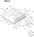
- FIG. 5 is a perspective view for illustrating the lower cover 22 and the board 3 in a state of the printer 1 illustrated in FIG. 4 .
- the dotted lines in FIG. 5 indicate the lower cover 22.
- FIG. 6 is a sectional perspective view for illustrating a state of the lower cover 22 and the board 3 taken along the line B-B of FIG. 5 and seen from the front side FR of the printer 1.
- FIG. 7 is a sectional perspective view for illustrating a state of the lower cover 22 and the board 3 taken along the line B-B of FIG. 5 and seen from the rear side RR of the printer 1.
- the lower cover 22 is provided on the lower side DW of the housing main body 21, and is placed on the placement surface G.
- the lower cover 22 includes a board cover 24 and the connector cover 25.
- the board cover 24 is mounted to the housing main body 21 from the lower side DW.
- the board cover 24 covers the board 3 accommodated in the casing 2.
- the board cover 24 includes a board cover bottom 240 and a board cover side wall 241.
- the board cover bottom 240 is a plate-like member that has a substantially rectangular shape and is provided on the lower side DW of the board cover 24.
- the board cover bottom 240 has the same shape as that of the housing main body 21 in plan view.
- the board cover bottom 240 includes a board cover groove 243 formed on the rear side RR.
- the board cover groove 243 is formed on the rear side RR of the board cover bottom 240. It is preferred that the board cover groove 243 be formed so as to be slightly longer in the front-and-rear direction than a connector 71a and a connector 72a that are respectively provided at ends of the cables 71 and 72 described above.
- the board cover groove 243 is formed into a substantially U shape including a bottom edge portion 243a on the front side FR and including side edge portions 243b in the right-and-left direction.
- a width of the board cover groove 243 in the right-and-left direction is not particularly limited.
- the width of the board cover groove 243 in the right-and-left direction is substantially equal to the width of the cable connection groove 215.
- the board cover bottom 240 is formed to have a length in the front-and-rear direction that allows the board 3 to be arranged within a sufficient space more on the front side FR than the board cover groove 243 under a state in which the board cover groove 243 is formed on the rear side RR.
- the board cover groove 243 is not an essential component.
- the board cover side wall 241 is formed along an edge portion 240a of the board cover bottom 240 excluding the board cover groove 243.
- the board cover side wall 241 is fixed to the housing main body 21 by a publicly-known method such as a bolt or an adhesive, and thus the housing main body 21 and the lower cover 22 are integrated with each other.
- the board cover side wall 241 is set to have a height capable of covering, for example, a portion of the board 3 protruding to the lower side DW when the board 3 is mounted to the housing main body 21.
- the connector cover 25 is provided on the rear side RR of the lower cover 22.
- the connector cover 25 covers the cable connection groove 215 formed in the rear wall 212 of the housing main body 21.
- the connector cover 25 includes a cover main body 26 and first opening cover portions 60.
- the connector cover 25 covers the cable connection groove 215 formed in the rear wall 212 of the housing main body 21.
- the front side FR with respect to the connector cover 25 is also referred to as a cable insertion side.
- the rear side RR with respect to the connector cover 25 is also referred to as a cable removal side. It is not always required that the connector cover 25 be arranged on the rear side RR of the housing main body 21, and arrangement of the connector cover 25 is not limited to that described in this embodiment.
- the cover main body 26 includes the opening cover mounting portion 261, side portions 262, and an upper wall portion 263.
- the opening cover mounting portion 261 is connected at a lower end portion thereof to the bottom edge portion 243a of the board cover groove 243, and extends upright to the upper side UP.
- the side portions 262 are each connected at a lower end portion thereof to the side edge portion 243b formed in the right-and-left direction of the board cover groove 243, and extend upright to the upper side UP.
- the upper wall portion 263 is fixed to an upper end portion of the opening cover mounting portion 261 and upper end portions of the side portions 262 so as to cover the upper side UP of the cover main body 26.
- the cover main body 26 defines a space S3 for covering connector portions of the cables described above. Accordingly, when the cables 71 and 72 are inserted into the connector unit 30 of the board 3, the cover main body 26 covers, within the space S3, the connectors 71a and 72a that are respectively provided at the ends of the cables 71 and 72, thereby being capable of preventing, for example, dust and dirt from easily entering the printer.
- the opening cover mounting portion 261 of the cover main body 26 includes a power supply opening portion 50, a plurality of first interface opening portions 51, and a second interface opening portion 52.
- the power supply opening portion 50 is an opening portion passing through the cover main body 26 in the front-and-rear direction.
- the power supply opening portion 50 has a size allowing the power cable 71 illustrated in FIG. 5 to be removably inserted through the power supply opening portion 50.
- the shape and size of the power supply opening portion 50 can be freely modified in accordance with a connection surface of a power supply connector 31 to which the power cable 71 is connectable.
- the power supply opening portion 50 is arranged in the opening cover mounting portion 261 so that the connection surface of the power supply connector 31 overlaps the power supply opening portion 50 when seen from the rear side RR in the front-and-rear direction. Further, a member such as a cover is not provided for covering the power supply opening portion 50.
- the power supply connector 31 is exposed.
- the power supply connector 31 which is provided more on the front side FR than the opening cover mounting portion 261 when seen from the rear side RR in the front-and-rear direction, is exposed.
- the first interface opening portions 51 are each an opening portion passing through the cover main body 26 in the front-and-rear direction.
- the first interface opening portion 51 has a size allowing the interface cable 72, which is described later, to be inserted through the first interface opening portion 51.
- the shape and size of the first interface opening portion 51 can be freely modified in accordance with a connection surface of an interface connector 32 to which the interface cable 72 is connectable.
- the first interface opening portion 51 is arranged in the opening cover mounting portion 261 so that the connection surface of the interface connector 32 overlaps the first interface opening portion 51 when seen from the rear side RR in the front-and-rear direction.
- the number of the first interface opening portions 51 is not particularly limited.
- Only one first interface opening portion 51 may be formed, or a plurality of first interface opening portions 51 may be formed. In this embodiment, two first interface opening portions 51 are formed more on the left side LH than the power supply opening portion 50.
- the first interface opening portion 51 can be formed in accordance with the number of the interface connectors 32 mounted on the board 3 of the printer 1.
- the second interface opening portion 52 is an opening portion passing through the cover main body 26 in the front-and-rear direction.
- the second interface opening portion 52 has a size allowing the interface cable 72, which is described later, to be inserted through the second interface opening portion 52.
- the shape and size of the second interface opening portion 52 can be freely modified in accordance with the connection surface of the interface connector 32 to which the interface cable 72 is connectable.
- the number of the second interface opening portions 52 is not particularly limited, and a plurality of second interface opening portions 52 may be formed. Further, the second interface opening portion 52 is not an essential component. In this embodiment, one second interface opening portion 52 is formed more on the right side RH than the power supply opening portion 50.
- the connector cover 25 further includes a second opening cover portion 65.
- the second opening cover portion 65 covers the second interface opening portion 52.
- the second opening cover portion 65 is removed during manufacture. Accordingly, through the second interface opening portion 52, the interface connector 32 is exposed.
- the interface connector 32 is provided more on the front side FR than the opening cover mounting portion 261 when seen from the rear side RR in the front-and-rear direction.
- the second opening cover portion 65 has the same configuration as that of each of the first opening cover portions 60 to be described later.
- the two first interface opening portions 51, the power supply opening portion 50, and the second interface opening portion 52 are arrayed in the stated order in the right-and-left direction.
- the order of the above-mentioned opening portions is not particularly limited.
- the above-mentioned opening portions are formed in the opening cover mounting portion 261 in accordance with the order of the connectors of the connector unit on the board.
- the first opening cover portions 60 each cover the first interface opening portion 51.
- the first opening cover portion 60 is provided slightly more on the front side FR than the opening cover mounting portion 261 in the front-and-rear direction.
- a clearance between the first opening cover portion 60 and the opening cover mounting portion 261 in the front-and-rear direction is set to be as small as possible, thereby being capable of further preventing entry of, for example, dust and dirt through the first interface opening portion 51.
- the first opening cover portions 60 of the same number as that of the first interface opening portions 51 are formed.
- a width of the first opening cover portion 60 in the front-and-rear direction is substantially equal to a width of the opening cover mounting portion 261.
- the first opening cover portion 60 is formed so as to have substantially the same shape and size as those of the first interface opening portion 51. Accordingly, the cover main body 26 can easily form the first opening cover portions 60 during manufacture. It is only required that the first opening cover portions 60 each cover at least a part of the first interface opening portion 51. As shown in Fig. 6 , the first opening cover portions 60 each include a first coupling portion 61 formed on the upper side UP, and a stopper 64 formed on the lower side DW.
- the second opening cover portion 65 has the same configuration as that of the first opening cover portion 60, and includes the first coupling portion 61 and the stopper 64. Herein, description of the second opening cover portion 65 is omitted.
- the first coupling portion 61 is formed in a portion of the first opening cover portion 60, and couples the first opening cover portion 60 and the opening cover mounting portion 261 of the cover main body 26 to each other.
- a shape of the first coupling portion 61 is not particularly limited.
- the first coupling portion 61 is formed on the upper side UP of the first opening cover portion 60.
- a width of the first coupling portion 61 in the front-and-rear direction is set to, for example, about 2.5 mm.
- the first coupling portion 61 includes a notched portion 62 (a notch) and a thin portion 63.
- the notched portion 62 is a portion obtained by forming a substantially V-shaped notch in a back surface 61b of the first coupling portion 61 from the rear side RR to the front side FR along the right-and-left direction.
- the shape of the notched portion 62 is not particularly limited.
- a notch width of the notched portion 62 is set so that the shortest distance from the deepest portion of the notched portion 62 to a front surface 61a of the first coupling portion 61 on the front side FR is about 1 mm.
- the notch width of the notched portion 62 is not particularly limited.
- the notch width of the notched portion 62 be designed so as to prevent the thin portion 63 from splitting in a manufacturing stage, but allow the thin portion 63 to easily split when a worker applies a pushing force (external force) to the first opening cover portion 60 toward the front side FR before product shipment.
- the thin portion 63 is a portion having a smaller thickness in the front-and-rear direction than the other portions of the first coupling portion 61.
- the thin portion 63 is a thin portion formed more on the front side FR than the notch (notched portion 62) of the first coupling portion 61.
- the thin portion 63 is formed on the front surface 61a of the first coupling portion 61 on the front side FR.
- the thickness of the thin portion 63 in the front-and-rear direction can be freely modified in accordance with the notched portion 62.
- the pushing force (external force) is applied to the first opening cover portion 60 toward the front side FR as described above, the first opening cover portion 60 is swung on the first coupling portion 61 along the front-and-rear direction. At this time, a shearing force acts more on the thin portion 63 having a smaller thickness in the front-and-rear direction than on the first coupling portion 61. Accordingly, the first coupling portion 61 is split from the thin portion 63.
- the stopper 64 is provided on the lower side DW of the first opening cover portion 60. Accordingly, the stopper 64 and the first coupling portion 61 are formed on both sides of the first opening cover portion 60 across a center axis passing a center of the first opening cover portion 60 in the up-and-down direction. The stopper 64 protrudes from a lower end portion of the first opening cover portion 60 to the lower side DW.
- the pushing force external force
- the first opening cover portion 60 is engaged with a rear edge portion 3p formed on the rear side RR of the board 3.
- the casing 2 has at least a space S1 and a space S2 that are defined inside the casing 2 by, for example, a plurality of partition plates provided inside the casing 2.
- the space S2 is defined on the lower side DW of the casing 2.
- the space S1 is a space having a size allowing the printing unit 4, which is described later, to be accommodated inside the space S1.
- the space S 1 is an enclosed space defined by the partition plates, the upper cover 20, and the housing main body 21. It is preferred that the space S 1 be defined more on the upper side UP in the up-and-down direction than an upper edge 215a of the cable connection groove 215. With this configuration, the housing main body 21 can keep an enclosed accommodation space of the space S 1.
- the space S2 is a space having such a size as to accommodate the board 3 therein.
- the space S2 is defined by a configuration in which the lower-end opening portion 21b of the housing main body 21 is covered with the board cover 24 of the lower cover 22 and the cable connection groove 215 of the rear wall 212 is covered with the connector cover 25 of the lower cover 22. With the above-mentioned configuration, the space S2 forms an enclosed space.
- the casing 2 is not limited to that described in this embodiment.
- the casing 2 may have a plurality of spaces defined by a plurality of partition plates.
- the board 3 is a circuit board on which a plurality of electronic components are mounted.
- the board 3 outputs an electric signal or a control signal in response to, for example, input from a button or an external device (not shown), or outputs a control signal so as to comprehensively control various kinds of functions of the printer 1.
- the board 3 is formed into a rectangular board shape having a pair of short sides in the front-and-rear direction corresponding to a long-side direction, and having a pair of long sides in the right-and-left direction corresponding to a short-side direction.
- the connector unit 30 is provided on an upper surface 3a of the board 3. Further, when the pushing force (external force) is applied to the first opening cover portion 60 toward the front side FR in the front-and-rear direction, the rear edge portion 3p of the board 3 on the rear side RR is engaged with the stopper 64.
- the connector unit 30 includes, for example, the power supply connector 31 and the interface connector 32.
- the connector unit 30 is not limited to that described in this embodiment.
- the connector unit 30 may include only one connector, or may include a plurality of connectors.
- the power supply connector 31 is provided on the upper surface 3a of the board 3.
- the power supply connector 31 is electrically connected to the board 3 via, for example, an electrical connection member (not shown).
- the power cable 71 can be connected to (inserted into and removed from) the power supply connector 31.
- the power supply connector 31 is arranged on the rear side RR of the board 3 under a state in which the connection surface, to which the power cable 71 is connectable, is directed to the rear side RR. Further, the power supply connector 31 is arranged so as to be exposed and visible through the power supply opening portion 50 when seen from the rear side RR in the front-and-rear direction.
- the interface connector 32 is provided on the upper surface 3a of the board 3.
- the interface connector 32 is electrically connected to the board 3 via, for example, an electrical connection member (not shown).
- the interface cable 72 can be connected to (inserted into and removed from) the interface connector 32.
- the interface connector 32 is, for example, a Universal Serial Bus (USB) connector. Further, in this case, the interface cable 72 is a USB connector.
- the interface connector 32 is arranged on the rear side RR of the board 3 under a state in which the connection surface, to which the interface cable 72 is connectable, is directed to the rear side RR. Further, the interface connector 32 is arranged so as to be exposed and visible through the second interface opening portion 52 when seen from the rear side RR in the front-and-rear direction.
- the interface connector 32 is not a particularly essential component.
- the interface connector 32 is not mounted on the board 3.
- the interface cable 72 is not limited to a USB connector.
- As the interface cable 72 for example, a Local Area Network (LAN) connector or an Ethernet standard connector can be used.
- LAN Local Area Network
- the connector unit 30 is provided on the short side (one side) of the board 3 on the rear side RR in the front-and-rear direction, which is close to the cover main body 26. Further, the connector unit 30 is arranged so as to be aligned along the short side of the board 3 on the rear side RR in the front-and-rear direction.
- the interface connector 32 is arranged more on the right side RH than the power supply connector 31. Further, on the left side LH of the power supply connector 31, the board 3 has a space allowing a plurality of interface connectors 32 to be further mounted in the space.
- the power supply connector 31 is mounted on the board 3 so as to be exposed through the power supply opening portion 50 when seen from the rear side RR in the front-and-rear direction.
- the interface connector 32 is mounted on the board 3 so as to be exposed through the second interface opening portion 52 when seen from the rear side RR in the front-and-rear direction.
- Intervals between connectors to be arranged are not particularly limited. However, it is desired that the connectors be arranged at intervals that are set in consideration of causing no noise when a plurality of cables respectively corresponding to the connectors are inserted into the connectors from an outside.
- the printing unit 4 includes a platen roller 40, a thermal head 41, and a cutter unit 42.
- the platen roller 40 is a rubber roller extending in the right-and-left direction.
- the platen roller 40 is provided in a front end part of the housing main body 21 (part located closer to the delivery slot 23).
- the platen roller 40 is rotatable about an axis O1 along the right-and-left direction, and is rotated in accordance with a driving force of a driving motor (not shown) when the recording sheet P is conveyed.
- the thermal head 41 is provided in a part of an inside of the upper cover 20 located closer to the delivery slot 23.
- the thermal head 41 includes a plurality of heating elements linearly arrayed along the right-and-left direction.
- the thermal head 41 is fixed to a front end portion of the upper cover 20 under a state in which the heating elements are directed downward.
- the platen roller 40 and the thermal head 41 are opposed to each other in the up-and-down direction through intermediation of the recording sheet P.
- the thermal head 41 is held in close contact with the platen roller 40.
- the recording sheet P is allowed to pass through a space between the platen roller 40 and the thermal head 41 along with rotation of the platen roller 40.
- a heating pattern of the heating elements of the thermal head 41 is controlled based on a signal output from the board 3. When heat of the heating elements is transferred to the print surface of the recording sheet P, information (such as characters and figures) associated with the heating pattern is printed on the recording sheet P.
- the cutter unit 42 includes a fixed blade 420 and a movable blade 421.
- the cutter unit 42 causes a moving mechanism (not shown) to reciprocate the movable blade 421 with respect to the recording sheet P, and sandwiches the recording sheet P between the movable blade 421 and the fixed blade 420, to thereby form a cut in the recording sheet P.
- a recessed portion (not shown) may be formed in a blade edge of the fixed blade 420 or a blade edge of the movable blade 421. Owing to provision of the recessed portion, when the cutter unit 42 cuts the recording sheet P, an uncut portion is left at a portion of the recording sheet P opposed to the recessed portion (so-called partial cutting).
- the number of the recessed portion is not particularly limited, and a plurality of recessed portions may be formed. Further, the recessed portion is not an essential component.
- the fixed blade 420 is arranged between the platen roller 40 and the delivery slot 23 in the housing main body 21 and on a side opposite to the print surface of the recording sheet P.
- the fixed blade 420 is formed into a plate-like shape extending in the right-and-left direction.
- a shape of the blade edge of the fixed blade 420 is not particularly limited.
- the fixed blade 420 is fixed through predetermined means by a support portion (not shown) provided in the housing main body 21.
- the movable blade 421 is arranged between the thermal head 41 and the delivery slot 23 in the upper cover 20 and on the print surface side of the recording sheet P.
- the movable blade 421 is formed into a plate-like shape extending in the right-and-left direction. Further, the movable blade 421 is fixed through predetermined means by a support portion (not shown) provided in the housing main body 21. Moreover, the movable blade 421 is reciprocated in an advancing direction B by the moving mechanism (not shown).
- FIG. 8 is a perspective view for illustrating a state in which the board 3 is mounted to the housing main body 21 of the printer 1 and the lower cover 22 is removed.
- a worker integrates the upper cover 20 and the housing main body 21 of the casing 2 with each other under a state in which the printing unit 4 is provided in the housing main body 21 of the printer 1.
- the board 3 is mounted to the housing main body 21.
- the board 3 is accommodated in the space S3 to be defined on the lower side DW of the casing 2.
- the connector unit 30, which is arrayed along the short side of the board 3 on the rear side RR in the front-and-rear direction, is mounted to the housing main body 21 so as to be directed to the rear side RR.
- the first coupling portion 61 is split from the thin portion 63.
- the second opening cover portion 65 is thus removed from the connector cover 25.
- the pushing force (external force) may be applied in the front-and-rear direction only once or a plurality of times.
- the second opening cover portion 65 is provided slightly more on the front side FR than the opening cover mounting portion 261 in the front-and-rear direction. Accordingly, a worker can easily push the second opening cover portion 65 to the front side FR.
- the lower cover 22 is mounted to the housing main body 21 from the lower side DW.
- the lower cover 22 is mounted so that the connector cover 25 is directed to the rear side RR.
- the lower cover 22 covers the lower-end opening portion 21b of the housing main body 21, and covers the cable connection groove 215 of the rear wall 212 of the housing main body 21.
- the second interface opening portion 52 is arranged on the rear side RR of the interface connector 32 of the board 3, and the interface connector 32 is exposed through the second interface opening portion 52.
- the lower cover 22 is mounted to and integrated with the housing main body 21. Through the above-mentioned manufacturing process, the printer 1 is produced.
- the connector cover 25 of the printer 1 includes the power supply opening portion 50, the first interface opening portions 51, and the second interface opening portion 52. Accordingly, without providing a plurality of connector covers 25 for the connectors mounted on the board 3, in accordance with various types of connectors mounted on the board 3, cables that are to be respectively connected to the connectors can be inserted through the opening portions and inserted into the connectors. In this embodiment, there is no need to prepare different connector covers for various types of connectors mounted on the board 3. Accordingly, the number of parts of the printer 1 can be reduced.
- each of the first interface opening portions 51, through which the cable is not inserted, is covered with the first opening cover portion 60. Accordingly, the first opening cover portion 60 closes the first interface opening portion 51, and thus can prevent entry of, for example, dust and dirt.
- no cover is provided for covering the power supply opening portion 50 to which the power supply connector 31 is arranged. Accordingly, without the need to remove a cover, the power cable 71 can be easily inserted into the power supply connector 31 that is typically mounted on the board 3.
- the second opening cover portion 65 when a worker applies the pushing force (external force) to the second opening cover portion 65, the second opening cover portion 65 can be removed from the connector cover 25. Accordingly, when there is the interface cable 72 that is intended to be inserted through the second interface opening portion 52, the second opening cover portion 65 can be removed from the connector cover 25 after the connector cover 25 is formed.
- the first opening cover portion 60 and the second opening cover portion 65 each include the thin portion 63 in the first coupling portion 61. Accordingly, when the first opening cover portion 60 or the second opening cover portion 65 is removed, without use of, for example, a cutting tool, a worker can easily remove the first opening cover portion 60 or the second opening cover portion 65 by hand.
- the first opening cover portion 60 and the second opening cover portion 65 each include the stopper 64. Accordingly, even when the first opening cover portion 60 or the second opening cover portion 65 is pushed to the front side FR, the stopper 64 is engaged with the rear edge portion 3p of the board 3, thereby being capable of preventing the first opening cover portion 60 or the second opening cover portion 65 from being removed. Further, the stopper 64 is formed on a side opposite to the first coupling portion 61 across the center axis passing the center of the first opening cover portion 60. Therefore, the first opening cover portion 60 or the second opening cover portion 65 can be inhibited from moving to the front side FR in the front-and-rear direction to cause splitting of the first coupling portion 61 from the thin portion 63.
- the thin portion 63 is formed on the front surface 61a of the first coupling portion 61 on the front side FR. Accordingly, even when a sharp projection such as a burr is formed at the time of removal of the first opening cover portion 60 or the second opening cover portion 65, the sharp projection is less liable to project more to the rear side RR than the cover main body 26 of the connector cover 25. Therefore, there can be eliminated a risk in that a worker is injured on his or her hand by a burr during use of the printer 1.
- the present invention is not limited by the embodiment described above. Further, the components in the embodiment encompass components easily conceived by a person skilled in the art, or substantially the same components. In addition, the components disclosed in the embodiment can be combined with each other as appropriate.
- the first opening cover portion in the present invention may be formed so as to be larger than the first interface opening portion, and may be formed so as to overlap the entire first interface opening portion when seen from the front-and-rear direction. With this configuration, a clearance between the first opening cover portion and the first interface opening portion is further reduced, thereby being capable of further preventing entry of, for example, dust and dirt.
- the first opening cover portion in the embodiment described above may include two or more first coupling portions. With this configuration, the first opening cover portion is fixed to the cover main body more firmly. Accordingly, there can be reduced a risk in that the first opening cover portion slips off the cover main body due to contact with a hand of a worker or vibration. Further, the first opening cover portion may further include a second coupling portion that couples the first opening cover portion and the cover main body to each other. The first opening cover portion includes the second coupling portion that is formed on a side opposite to the first coupling portion across the center axis passing the center of the first opening cover portion.
- the first coupling portion and the second coupling portion are formed on both sides of the first opening cover portion across the center axis passing the center of the first opening cover portion.
- the first opening cover portion is fixed to the cover main body more firmly. Accordingly, the same effects as those described above can be obtained.
- the second coupling portion may be formed so as to have a sectional area smaller than that of the first coupling portion.
- the second opening cover portion may also have the same configuration as that described above.
- a thermal printer is described as an example, but the printer is not particularly limited.
- the present invention is applicable to various types of printers.
- the cover that is compatible with a plurality of interfaces can prevent entry of dust and dirt into the printer.
Landscapes
- Engineering & Computer Science (AREA)
- Multimedia (AREA)
- Signal Processing (AREA)
- Physics & Mathematics (AREA)
- General Physics & Mathematics (AREA)
- Microelectronics & Electronic Packaging (AREA)
- Accessory Devices And Overall Control Thereof (AREA)
- Insertion, Bundling And Securing Of Wires For Electric Apparatuses (AREA)
Abstract
Description
- The present invention relates to a printer.
- Hitherto, for a circuit board accommodated in a housing of a printer, a power supply connector has been used in order to enable electric power to be supplied (power supply) from a power supply device such as an AC power supply device so as to operate the printer. Further, in general, an interface connector is used in order to enable transmission and reception of an electric signal from an external device. (See, for example,
Japanese Patent Application Laid-open No. 2011-142057 - However, in a case of a device like the above-mentioned related-art printer, which is compatible with a board allowing a plurality of interface connectors to be mounted on the board, it is required that a connector cover being an exterior component be set in accordance with the connectors mounted on the board. In this case, one connector cover can be employed when a plurality of opening portions are formed in the one connector cover in advance so that cables to be connected to the connectors can be inserted through the plurality of opening portions. However, an opening portion, through which a cable is not inserted, allows entry of, for example, dust and dirt into the printer. Therefore, it has been required to separately and additionally provide a cover for covering the opening portion, or to prepare a connector cover in which the opening portion through which a cable is not inserted is covered during manufacture.
- The present invention has been made in view of the above-mentioned circumstances, and has an object to provide a printer capable of preventing entry of dust and dirt into the printer with a cover that is compatible with a plurality of interfaces.
- According to one embodiment of the present invention, there is provided printer including: a board including a connector unit that includes at least a power supply connector into which a power cable is to be removably inserted; and a housing including: a housing main body that accommodates the board and includes a cable connection groove through which the power cable is inserted in an inserting and removing direction of the power cable; and a connector cover configured to cover the cable connection groove, wherein the connector cover includes: a cover main body including a power supply opening portion passing through the cover main body in the inserting and removing direction, and a first interface opening portion passing through the cover main body in the inserting and removing direction; and a first opening cover portion configured to cover at least a part of the first interface opening portion, wherein the first opening cover portion includes a first coupling portion configured to couple the first opening cover portion and the cover main body to each other.
- In the above-mentioned printer according to the one embodiment of the present invention, preferably the connector unit further includes an interface connector into which an interface cable is removably inserted in the inserting and removing direction, and
the cover main body of the connector cover further includes a second interface opening portion passing through the cover main body in the inserting and removing direction. - In the above-mentioned printer according to the one embodiment of the present invention, preferably, from the second interface opening portion, a second opening cover portion configured to cover the second interface opening portion formed in the connector cover is removed during manufacture, and, through the second interface opening portion, the interface connector is exposed when seen from the inserting and removing direction.
- In the above-mentioned printer according to the one embodiment of the present invention, preferably the connector unit is arrayed on one side of the board close to the cover main body and along the one side.
- In the above-mentioned printer according to the one embodiment of the present invention, preferably the power supply connector is exposed through the power supply opening portion when seen from the inserting and removing direction.
- In the above-mentioned printer according to the one embodiment of the present invention, preferably the connector cover includes at least two first interface opening portions and at least two first opening cover portions.
- In the above-mentioned printer according to the one embodiment of the present invention, preferably the first coupling portion includes a thin portion having a smaller thickness in the inserting and removing direction than other portions of the first coupling portion.
- In the above-mentioned printer according to the one embodiment of the present invention, preferably the first coupling portion is split from the thin portion when an external force is applied to the first opening cover portion.
- In the above-mentioned printer according to the one embodiment of the present invention, preferably no cover is provided for covering the power supply opening portion.
- In the above-mentioned printer according to the one embodiment of the present invention, preferably the first opening cover portion includes a stopper that is engaged with an edge portion of the board when an external force is applied to the first opening cover portion to an insertion side in the inserting and removing direction.
- In the above-mentioned printer according to the one embodiment of the present invention, preferably the stopper and the first coupling portion are formed on both sides of the first opening cover portion across a center axis passing a center of the first opening cover portion.
- In the above-mentioned printer according to the one embodiment of the present invention, preferably the first opening cover portion includes two or more first coupling portions.
- In the above-mentioned printer according to the one embodiment of the present invention, preferably the first opening cover portion further includes a second coupling portion configured to couple the first opening cover portion and the cover main body to each other, and the first coupling portion and the second coupling portion are formed on both sides of the first opening cover portion across the center axis passing the center of the first opening cover portion.
- In the above-mentioned printer according to the one embodiment of the present invention, preferably the first opening cover portion is formed so as to be larger than the first interface opening portion, and formed so as to overlap the entire first interface opening portion when seen from the inserting and removing direction.
-
-
FIG. 1 is a perspective view for illustrating a printer according to an embodiment of the present invention. -
FIG. 2 is a side view for illustrating the printer when seen from a rear side thereof. -
FIG. 3 is a sectional side view for illustrating an internal configuration of the printer taken along the line A-A ofFIG. 1 . -
FIG. 4 is a sectional perspective view for illustrating the internal configuration of the entire printer taken along the line A-A ofFIG. 1 at portions other than a lower cover and a board of the printer. -
FIG. 5 is a perspective view for illustrating the lower cover and the board in a state of the printer illustrated inFIG. 4 . -
FIG. 6 is a sectional perspective view for illustrating a state of the lower cover and the board taken along the line B-B ofFIG. 5 and seen from a front side of the printer. -
FIG. 7 is a sectional perspective view for illustrating a state of the lower cover and the board taken along the line B-B ofFIG. 5 and seen from the rear side of the printer. -
FIG. 8 is a perspective view for illustrating a state in which the board is mounted to a housing main body of the printer and the lower cover is removed. - An embodiment of the present invention is described by way of example only with reference to
FIG. 1 to FIG. 8 . In the embodiment and modification examples described below, corresponding configurations are denoted by the same reference symbols, and description thereof is omitted in some cases. In the following description, expressions such as "parallel", "orthogonal", "center", and "coaxial", which express relative or absolute arrangement, not only represent such arrangement in the strict sense of the word, but also represent a relatively displaced state with an angle or a distance that falls within tolerance or achieves the same function. -
FIG. 1 is a perspective view for illustrating aprinter 1 according to an embodiment of the present invention.FIG. 2 is a side view for illustrating theprinter 1 when seen from a rear side RR thereof.FIG. 3 is a sectional side view for illustrating an internal configuration of theprinter 1 taken along the line A-A ofFIG. 1 .FIG. 4 is a sectional perspective view for illustrating the internal configuration of theentire printer 1 taken along the line A-A ofFIG. 1 at portions other than alower cover 22 and aboard 3 of theprinter 1. - In this embodiment, the
printer 1 is a thermal printer that performs printing on a recording sheet P through heat. Theprinter 1 performs printing on the recording sheet P. The recording sheet P in this embodiment is, for example, a heat sensitive roll sheet to be used for a thermal printing system. Under a state in which a print surface of the recording sheet P is directed outward, the recording sheet P is wound around a tubular core material R1 (seeFIG. 3 ), thereby forming a roll sheet R. The roll sheet R may have a configuration without the core material R1. As illustrated inFIG. 3 , theprinter 1 includes a casing (housing) 2, theboard 3, and aprinting unit 4. - Here, the
printer 1 is placed on a placement surface G. In the following description, a direction perpendicular to the placement surface G is referred to as an up-and-down direction. An upper side in the up-and-down direction is referred to as an upper side UP, and a side opposite to the upper side UP is referred to as a lower side DW. Further, a direction in which the recording sheet P is to be conveyed, which is orthogonal to the up-and-down direction, is referred to as a front-and-rear direction. One side in the front-and-rear direction on which the recording sheet P is to be delivered from theprinter 1 is referred to as a front side FR, and a side opposite to the front side FR is referred to as a rear side RR. Further, a direction orthogonal to the up-and-down direction and the front-and-rear direction is referred to as a right-and-left direction. One side in the right-and-left direction is referred to as a left side LH, and a side opposite to the left side LH is referred to as a right side RH. - The casing (housing) 2 is formed into a box shape. The
casing 2 accommodates, in an accommodation space thereof, theboard 3 and theprinting unit 4. It is preferred that thecasing 2 define the accommodation space in a hermetic manner so as to protect theboard 3 and theprinting unit 4 from, for example, moisture and dust. Thecasing 2 includes anupper cover 20, a housingmain body 21, and thelower cover 22. - As illustrated in
FIG. 3 , theupper cover 20 opens and closes an upper-end opening portion 21a of the housingmain body 21. Specifically, theupper cover 20 is formed into a box shape opened to the lower side DW, and has the same shape as that of the housingmain body 21 in plan view. In a closing position, theupper cover 20 is superposed on the housingmain body 21 from the upper side UP, and closes the upper-end opening portion 21a of the housingmain body 21. Further, in this state, adelivery slot 23 is defined between the housingmain body 21 and theupper cover 20. Thedelivery slot 23 allows communication between an inside and an outside of thecasing 2, and has a slit shape extending in the right-and-left direction. Through thedelivery slot 23, the recording sheet P having been subjected to printing by theprinting unit 4 is delivered toward the front side FR. Meanwhile, in an opening position, theupper cover 20 retreats from an upper side of the housingmain body 21, and opens the upper-end opening portion 21a of the housingmain body 21. - As illustrated in
FIG. 2 to FIG. 4 , the housingmain body 21 includes the upper-end opening portion 21a on the upper side UP, and a lower-end opening portion 21b on the lower side DW. The housingmain body 21 is formed into a bottomless box shape including afront wall 211 and arear wall 212 in the front-and-rear direction and including aleft wall 213 and aright wall 214 in the right-and-left direction. Thefront wall 211, therear wall 212, theleft wall 213, and theright wall 214 are each a part of an outer wall of the housingmain body 21. - The
front wall 211 is provided on the front side FR of the housingmain body 21. Therear wall 212 is provided on the rear side RR of the housingmain body 21. Thefront wall 211 and therear wall 212 have substantially the same size and shape, and are each a plate-like member arranged along a horizontal plane defined in the up-and-down direction and the right-and-left direction. Theleft wall 213 is provided on the left side LH of the housingmain body 21. Theright wall 214 is provided on the right side RH of the housingmain body 21. Theleft wall 213 and theright wall 214 have substantially the same size and shape, and are each a plate-like member arranged along a horizontal plane defined in the up-and-down direction and the front-and-rear direction. - In this embodiment, the housing
main body 21 includes acable connection groove 215 formed in therear wall 212. Thecable connection groove 215 is formed on the lower side DW of therear wall 212. Thecable connection groove 215 allows, for example, apower cable 71 or an interface cable 72 (seeFIG. 5 ) to be inserted therethrough in the front-and-rear direction. A width of thecable connection groove 215 in the right-and-left direction is not particularly limited. In this embodiment, thecable connection groove 215 has a width that allows insertion of the above-mentioned cables, and prevents all of a plurality of opening portions of an openingcover mounting portion 261 of aconnector cover 25 to be described later from overlapping thecable connection groove 215. - Here, the
power cable 71 or theinterface cable 72 can be inserted into aconnector unit 30 of theboard 3 from the rear side RR to the front side FR in the front-and-rear direction and removed from theconnector unit 30 of theboard 3, that is, thepower cable 71 or theinterface cable 72 is removably inserted into theconnector unit 30. The front-and-rear direction substantially matches a direction of inserting and removing the cable. -
FIG. 5 is a perspective view for illustrating thelower cover 22 and theboard 3 in a state of theprinter 1 illustrated inFIG. 4 . The dotted lines inFIG. 5 indicate thelower cover 22.FIG. 6 is a sectional perspective view for illustrating a state of thelower cover 22 and theboard 3 taken along the line B-B ofFIG. 5 and seen from the front side FR of theprinter 1.FIG. 7 is a sectional perspective view for illustrating a state of thelower cover 22 and theboard 3 taken along the line B-B ofFIG. 5 and seen from the rear side RR of theprinter 1. - The
lower cover 22 is provided on the lower side DW of the housingmain body 21, and is placed on the placement surface G. Thelower cover 22 includes aboard cover 24 and theconnector cover 25. - The
board cover 24 is mounted to the housingmain body 21 from the lower side DW. Theboard cover 24 covers theboard 3 accommodated in thecasing 2. Theboard cover 24 includes aboard cover bottom 240 and a boardcover side wall 241. - The
board cover bottom 240 is a plate-like member that has a substantially rectangular shape and is provided on the lower side DW of theboard cover 24. Theboard cover bottom 240 has the same shape as that of the housingmain body 21 in plan view. Theboard cover bottom 240 includes aboard cover groove 243 formed on the rear side RR. - As illustrated in
FIG. 5 , theboard cover groove 243 is formed on the rear side RR of theboard cover bottom 240. It is preferred that theboard cover groove 243 be formed so as to be slightly longer in the front-and-rear direction than aconnector 71a and aconnector 72a that are respectively provided at ends of thecables board cover groove 243 is formed into a substantially U shape including abottom edge portion 243a on the front side FR and includingside edge portions 243b in the right-and-left direction. A width of theboard cover groove 243 in the right-and-left direction is not particularly limited. However, in this embodiment, the width of theboard cover groove 243 in the right-and-left direction is substantially equal to the width of thecable connection groove 215. Theboard cover bottom 240 is formed to have a length in the front-and-rear direction that allows theboard 3 to be arranged within a sufficient space more on the front side FR than theboard cover groove 243 under a state in which theboard cover groove 243 is formed on the rear side RR. Theboard cover groove 243 is not an essential component. - As illustrated in
FIG. 5 , the boardcover side wall 241 is formed along anedge portion 240a of theboard cover bottom 240 excluding theboard cover groove 243. The boardcover side wall 241 is fixed to the housingmain body 21 by a publicly-known method such as a bolt or an adhesive, and thus the housingmain body 21 and thelower cover 22 are integrated with each other. The boardcover side wall 241 is set to have a height capable of covering, for example, a portion of theboard 3 protruding to the lower side DW when theboard 3 is mounted to the housingmain body 21. - As illustrated in
FIG. 4 orFIG. 5 , theconnector cover 25 is provided on the rear side RR of thelower cover 22. Theconnector cover 25 covers thecable connection groove 215 formed in therear wall 212 of the housingmain body 21. Theconnector cover 25 includes a covermain body 26 and firstopening cover portions 60. - Here, in the front-and-rear direction being the direction of inserting and removing the cable, the
connector cover 25 covers thecable connection groove 215 formed in therear wall 212 of the housingmain body 21. In the following description, the front side FR with respect to theconnector cover 25 is also referred to as a cable insertion side. Further, the rear side RR with respect to theconnector cover 25 is also referred to as a cable removal side. It is not always required that theconnector cover 25 be arranged on the rear side RR of the housingmain body 21, and arrangement of theconnector cover 25 is not limited to that described in this embodiment. - As illustrated in
FIG. 4 , the covermain body 26 includes the openingcover mounting portion 261,side portions 262, and anupper wall portion 263. The openingcover mounting portion 261 is connected at a lower end portion thereof to thebottom edge portion 243a of theboard cover groove 243, and extends upright to the upper side UP. Theside portions 262 are each connected at a lower end portion thereof to theside edge portion 243b formed in the right-and-left direction of theboard cover groove 243, and extend upright to the upper side UP. Theupper wall portion 263 is fixed to an upper end portion of the openingcover mounting portion 261 and upper end portions of theside portions 262 so as to cover the upper side UP of the covermain body 26. With this configuration, the covermain body 26 defines a space S3 for covering connector portions of the cables described above. Accordingly, when thecables connector unit 30 of theboard 3, the covermain body 26 covers, within the space S3, theconnectors cables - The opening
cover mounting portion 261 of the covermain body 26 includes a powersupply opening portion 50, a plurality of firstinterface opening portions 51, and a secondinterface opening portion 52. - The power
supply opening portion 50 is an opening portion passing through the covermain body 26 in the front-and-rear direction. The powersupply opening portion 50 has a size allowing thepower cable 71 illustrated inFIG. 5 to be removably inserted through the powersupply opening portion 50. The shape and size of the powersupply opening portion 50 can be freely modified in accordance with a connection surface of apower supply connector 31 to which thepower cable 71 is connectable. The powersupply opening portion 50 is arranged in the openingcover mounting portion 261 so that the connection surface of thepower supply connector 31 overlaps the powersupply opening portion 50 when seen from the rear side RR in the front-and-rear direction. Further, a member such as a cover is not provided for covering the powersupply opening portion 50. Accordingly, through the powersupply opening portion 50, thepower supply connector 31 is exposed. Through the powersupply opening portion 50, thepower supply connector 31, which is provided more on the front side FR than the openingcover mounting portion 261 when seen from the rear side RR in the front-and-rear direction, is exposed. - The first
interface opening portions 51 are each an opening portion passing through the covermain body 26 in the front-and-rear direction. The firstinterface opening portion 51 has a size allowing theinterface cable 72, which is described later, to be inserted through the firstinterface opening portion 51. The shape and size of the firstinterface opening portion 51 can be freely modified in accordance with a connection surface of aninterface connector 32 to which theinterface cable 72 is connectable. The firstinterface opening portion 51 is arranged in the openingcover mounting portion 261 so that the connection surface of theinterface connector 32 overlaps the firstinterface opening portion 51 when seen from the rear side RR in the front-and-rear direction. The number of the firstinterface opening portions 51 is not particularly limited. Only one firstinterface opening portion 51 may be formed, or a plurality of firstinterface opening portions 51 may be formed. In this embodiment, two firstinterface opening portions 51 are formed more on the left side LH than the powersupply opening portion 50. The firstinterface opening portion 51 can be formed in accordance with the number of theinterface connectors 32 mounted on theboard 3 of theprinter 1. - The second
interface opening portion 52 is an opening portion passing through the covermain body 26 in the front-and-rear direction. The secondinterface opening portion 52 has a size allowing theinterface cable 72, which is described later, to be inserted through the secondinterface opening portion 52. The shape and size of the secondinterface opening portion 52 can be freely modified in accordance with the connection surface of theinterface connector 32 to which theinterface cable 72 is connectable. The number of the secondinterface opening portions 52 is not particularly limited, and a plurality of secondinterface opening portions 52 may be formed. Further, the secondinterface opening portion 52 is not an essential component. In this embodiment, one secondinterface opening portion 52 is formed more on the right side RH than the powersupply opening portion 50. - Here, the
connector cover 25 further includes a secondopening cover portion 65. The secondopening cover portion 65 covers the secondinterface opening portion 52. However, as illustrated inFIG. 2 , the secondopening cover portion 65 is removed during manufacture. Accordingly, through the secondinterface opening portion 52, theinterface connector 32 is exposed. Theinterface connector 32 is provided more on the front side FR than the openingcover mounting portion 261 when seen from the rear side RR in the front-and-rear direction. The secondopening cover portion 65 has the same configuration as that of each of the firstopening cover portions 60 to be described later. - In the opening
cover mounting portion 261, the two firstinterface opening portions 51, the powersupply opening portion 50, and the secondinterface opening portion 52 are arrayed in the stated order in the right-and-left direction. However, the order of the above-mentioned opening portions is not particularly limited. The above-mentioned opening portions are formed in the openingcover mounting portion 261 in accordance with the order of the connectors of the connector unit on the board. - The first
opening cover portions 60 each cover the firstinterface opening portion 51. The firstopening cover portion 60 is provided slightly more on the front side FR than the openingcover mounting portion 261 in the front-and-rear direction. A clearance between the firstopening cover portion 60 and the openingcover mounting portion 261 in the front-and-rear direction is set to be as small as possible, thereby being capable of further preventing entry of, for example, dust and dirt through the firstinterface opening portion 51. The firstopening cover portions 60 of the same number as that of the firstinterface opening portions 51 are formed. A width of the firstopening cover portion 60 in the front-and-rear direction is substantially equal to a width of the openingcover mounting portion 261. Further, the firstopening cover portion 60 is formed so as to have substantially the same shape and size as those of the firstinterface opening portion 51. Accordingly, the covermain body 26 can easily form the firstopening cover portions 60 during manufacture. It is only required that the firstopening cover portions 60 each cover at least a part of the firstinterface opening portion 51. As shown inFig. 6 , the firstopening cover portions 60 each include afirst coupling portion 61 formed on the upper side UP, and astopper 64 formed on the lower side DW. In this embodiment, the secondopening cover portion 65 has the same configuration as that of the firstopening cover portion 60, and includes thefirst coupling portion 61 and thestopper 64. Herein, description of the secondopening cover portion 65 is omitted. - The
first coupling portion 61 is formed in a portion of the firstopening cover portion 60, and couples the firstopening cover portion 60 and the openingcover mounting portion 261 of the covermain body 26 to each other. A shape of thefirst coupling portion 61 is not particularly limited. In this embodiment, thefirst coupling portion 61 is formed on the upper side UP of the firstopening cover portion 60. However, it is only required that thefirst coupling portion 61 be formed in a portion of the firstopening cover portion 60, and a formation position of thefirst coupling portion 61 is not particularly limited. A width of thefirst coupling portion 61 in the front-and-rear direction is set to, for example, about 2.5 mm. Thefirst coupling portion 61 includes a notched portion 62 (a notch) and athin portion 63. - As illustrated in
FIG. 6 , the notchedportion 62 is a portion obtained by forming a substantially V-shaped notch in aback surface 61b of thefirst coupling portion 61 from the rear side RR to the front side FR along the right-and-left direction. The shape of the notchedportion 62 is not particularly limited. In this embodiment, a notch width of the notchedportion 62 is set so that the shortest distance from the deepest portion of the notchedportion 62 to afront surface 61a of thefirst coupling portion 61 on the front side FR is about 1 mm. The notch width of the notchedportion 62 is not particularly limited. However, it is preferred that the notch width of the notchedportion 62 be designed so as to prevent thethin portion 63 from splitting in a manufacturing stage, but allow thethin portion 63 to easily split when a worker applies a pushing force (external force) to the firstopening cover portion 60 toward the front side FR before product shipment. - As illustrated in
FIG. 6 , thethin portion 63 is a portion having a smaller thickness in the front-and-rear direction than the other portions of thefirst coupling portion 61. Specifically, thethin portion 63 is a thin portion formed more on the front side FR than the notch (notched portion 62) of thefirst coupling portion 61. Thethin portion 63 is formed on thefront surface 61a of thefirst coupling portion 61 on the front side FR. The thickness of thethin portion 63 in the front-and-rear direction can be freely modified in accordance with the notchedportion 62. When the pushing force (external force) is applied to the firstopening cover portion 60 toward the front side FR as described above, the firstopening cover portion 60 is swung on thefirst coupling portion 61 along the front-and-rear direction. At this time, a shearing force acts more on thethin portion 63 having a smaller thickness in the front-and-rear direction than on thefirst coupling portion 61. Accordingly, thefirst coupling portion 61 is split from thethin portion 63. - As illustrated in
FIG. 6 , thestopper 64 is provided on the lower side DW of the firstopening cover portion 60. Accordingly, thestopper 64 and thefirst coupling portion 61 are formed on both sides of the firstopening cover portion 60 across a center axis passing a center of the firstopening cover portion 60 in the up-and-down direction. Thestopper 64 protrudes from a lower end portion of the firstopening cover portion 60 to the lower side DW. When the pushing force (external force) is applied to the firstopening cover portion 60 toward the front side FR (insertion side) in the front-and-rear direction, the firstopening cover portion 60 is engaged with arear edge portion 3p formed on the rear side RR of theboard 3. - As shown in
Fig. 3 , thecasing 2 has at least a space S1 and a space S2 that are defined inside thecasing 2 by, for example, a plurality of partition plates provided inside thecasing 2. The space S2 is defined on the lower side DW of thecasing 2. - The space S1 is a space having a size allowing the
printing unit 4, which is described later, to be accommodated inside the space S1. In this embodiment, thespace S 1 is an enclosed space defined by the partition plates, theupper cover 20, and the housingmain body 21. It is preferred that thespace S 1 be defined more on the upper side UP in the up-and-down direction than anupper edge 215a of thecable connection groove 215. With this configuration, the housingmain body 21 can keep an enclosed accommodation space of thespace S 1. - The space S2 is a space having such a size as to accommodate the
board 3 therein. The space S2 is defined by a configuration in which the lower-end opening portion 21b of the housingmain body 21 is covered with theboard cover 24 of thelower cover 22 and thecable connection groove 215 of therear wall 212 is covered with theconnector cover 25 of thelower cover 22. With the above-mentioned configuration, the space S2 forms an enclosed space. Thecasing 2 is not limited to that described in this embodiment. Thecasing 2 may have a plurality of spaces defined by a plurality of partition plates. - The
board 3 is a circuit board on which a plurality of electronic components are mounted. Theboard 3 outputs an electric signal or a control signal in response to, for example, input from a button or an external device (not shown), or outputs a control signal so as to comprehensively control various kinds of functions of theprinter 1. Theboard 3 is formed into a rectangular board shape having a pair of short sides in the front-and-rear direction corresponding to a long-side direction, and having a pair of long sides in the right-and-left direction corresponding to a short-side direction. Theconnector unit 30 is provided on anupper surface 3a of theboard 3. Further, when the pushing force (external force) is applied to the firstopening cover portion 60 toward the front side FR in the front-and-rear direction, therear edge portion 3p of theboard 3 on the rear side RR is engaged with thestopper 64. - The
connector unit 30 includes, for example, thepower supply connector 31 and theinterface connector 32. Theconnector unit 30 is not limited to that described in this embodiment. Theconnector unit 30 may include only one connector, or may include a plurality of connectors. - The
power supply connector 31 is provided on theupper surface 3a of theboard 3. Thepower supply connector 31 is electrically connected to theboard 3 via, for example, an electrical connection member (not shown). Thepower cable 71 can be connected to (inserted into and removed from) thepower supply connector 31. Thepower supply connector 31 is arranged on the rear side RR of theboard 3 under a state in which the connection surface, to which thepower cable 71 is connectable, is directed to the rear side RR. Further, thepower supply connector 31 is arranged so as to be exposed and visible through the powersupply opening portion 50 when seen from the rear side RR in the front-and-rear direction. - Similarly to the
power supply connector 31, theinterface connector 32 is provided on theupper surface 3a of theboard 3. Theinterface connector 32 is electrically connected to theboard 3 via, for example, an electrical connection member (not shown). Theinterface cable 72 can be connected to (inserted into and removed from) theinterface connector 32. Theinterface connector 32 is, for example, a Universal Serial Bus (USB) connector. Further, in this case, theinterface cable 72 is a USB connector. Theinterface connector 32 is arranged on the rear side RR of theboard 3 under a state in which the connection surface, to which theinterface cable 72 is connectable, is directed to the rear side RR. Further, theinterface connector 32 is arranged so as to be exposed and visible through the secondinterface opening portion 52 when seen from the rear side RR in the front-and-rear direction. Theinterface connector 32 is not a particularly essential component. When theprinter 1 performs wireless communication through, for example, Bluetooth (trademark), theinterface connector 32 is not mounted on theboard 3. Theinterface cable 72 is not limited to a USB connector. As theinterface cable 72, for example, a Local Area Network (LAN) connector or an Ethernet standard connector can be used. - The
connector unit 30 is provided on the short side (one side) of theboard 3 on the rear side RR in the front-and-rear direction, which is close to the covermain body 26. Further, theconnector unit 30 is arranged so as to be aligned along the short side of theboard 3 on the rear side RR in the front-and-rear direction. In this embodiment, theinterface connector 32 is arranged more on the right side RH than thepower supply connector 31. Further, on the left side LH of thepower supply connector 31, theboard 3 has a space allowing a plurality ofinterface connectors 32 to be further mounted in the space. Under this state, thepower supply connector 31 is mounted on theboard 3 so as to be exposed through the powersupply opening portion 50 when seen from the rear side RR in the front-and-rear direction. Further, theinterface connector 32 is mounted on theboard 3 so as to be exposed through the secondinterface opening portion 52 when seen from the rear side RR in the front-and-rear direction. Intervals between connectors to be arranged are not particularly limited. However, it is desired that the connectors be arranged at intervals that are set in consideration of causing no noise when a plurality of cables respectively corresponding to the connectors are inserted into the connectors from an outside. - As illustrated in
FIG. 3 , theprinting unit 4 includes aplaten roller 40, athermal head 41, and acutter unit 42. - The
platen roller 40 is a rubber roller extending in the right-and-left direction. Theplaten roller 40 is provided in a front end part of the housing main body 21 (part located closer to the delivery slot 23). Theplaten roller 40 is rotatable about an axis O1 along the right-and-left direction, and is rotated in accordance with a driving force of a driving motor (not shown) when the recording sheet P is conveyed. - The
thermal head 41 is provided in a part of an inside of theupper cover 20 located closer to thedelivery slot 23. Thethermal head 41 includes a plurality of heating elements linearly arrayed along the right-and-left direction. Thethermal head 41 is fixed to a front end portion of theupper cover 20 under a state in which the heating elements are directed downward. - The
platen roller 40 and thethermal head 41 are opposed to each other in the up-and-down direction through intermediation of the recording sheet P. When theupper cover 20 is at the closed position, thethermal head 41 is held in close contact with theplaten roller 40. The recording sheet P is allowed to pass through a space between theplaten roller 40 and thethermal head 41 along with rotation of theplaten roller 40. A heating pattern of the heating elements of thethermal head 41 is controlled based on a signal output from theboard 3. When heat of the heating elements is transferred to the print surface of the recording sheet P, information (such as characters and figures) associated with the heating pattern is printed on the recording sheet P. - As illustrated in
FIG. 3 , thecutter unit 42 includes a fixedblade 420 and amovable blade 421. Thecutter unit 42 causes a moving mechanism (not shown) to reciprocate themovable blade 421 with respect to the recording sheet P, and sandwiches the recording sheet P between themovable blade 421 and the fixedblade 420, to thereby form a cut in the recording sheet P. In thecutter unit 42, a recessed portion (not shown) may be formed in a blade edge of the fixedblade 420 or a blade edge of themovable blade 421. Owing to provision of the recessed portion, when thecutter unit 42 cuts the recording sheet P, an uncut portion is left at a portion of the recording sheet P opposed to the recessed portion (so-called partial cutting). The number of the recessed portion is not particularly limited, and a plurality of recessed portions may be formed. Further, the recessed portion is not an essential component. - As illustrated in
FIG. 3 , the fixedblade 420 is arranged between theplaten roller 40 and thedelivery slot 23 in the housingmain body 21 and on a side opposite to the print surface of the recording sheet P. The fixedblade 420 is formed into a plate-like shape extending in the right-and-left direction. A shape of the blade edge of the fixedblade 420 is not particularly limited. For example, there can be used a fixed blade having a blade edge of a conventionally-known shape such as a V shape extending in the up-and-down direction. The fixedblade 420 is fixed through predetermined means by a support portion (not shown) provided in the housingmain body 21. - As illustrated in
FIG. 3 , themovable blade 421 is arranged between thethermal head 41 and thedelivery slot 23 in theupper cover 20 and on the print surface side of the recording sheet P. Themovable blade 421 is formed into a plate-like shape extending in the right-and-left direction. Further, themovable blade 421 is fixed through predetermined means by a support portion (not shown) provided in the housingmain body 21. Moreover, themovable blade 421 is reciprocated in an advancing direction B by the moving mechanism (not shown). - Next, as operations of the above-mentioned
printer 1, a method of manufacturing theprinter 1 is described. -
FIG. 8 is a perspective view for illustrating a state in which theboard 3 is mounted to the housingmain body 21 of theprinter 1 and thelower cover 22 is removed. - First, as illustrated in
FIG. 8 , a worker integrates theupper cover 20 and the housingmain body 21 of thecasing 2 with each other under a state in which theprinting unit 4 is provided in the housingmain body 21 of theprinter 1. Then, theboard 3 is mounted to the housingmain body 21. Theboard 3 is accommodated in the space S3 to be defined on the lower side DW of thecasing 2. At this time, theconnector unit 30, which is arrayed along the short side of theboard 3 on the rear side RR in the front-and-rear direction, is mounted to the housingmain body 21 so as to be directed to the rear side RR. - Next, in order to removably insert cables compatible with the
connector unit 30 provided on theboard 3, a worker removes covers of theconnector cover 25 that cover the opening portions, respectively. In this embodiment, no cover is provided for covering the powersupply opening portion 50. Further, the firstinterface opening portions 51 are covered with the firstopening cover portions 60, respectively. However, theboard 3 does not include connectors into which cables are removably inserted through the firstinterface opening portions 51. Accordingly, the firstopening cover portions 60 are not removed from the firstinterface opening portions 51. - The
board 3 includes theinterface connector 32 into which theinterface cable 72 is removably inserted through the secondinterface opening portion 52. Accordingly, a worker removes, from the secondinterface opening portion 52, the secondopening cover portion 65 that covers the secondinterface opening portion 52 formed in theconnector cover 25. Specifically, the secondopening cover portion 65 has the same configuration as that of the firstopening cover portion 60 as described above. Accordingly, when the pushing force (external force) is applied to the secondopening cover portion 65 toward the front side FR, the secondopening cover portion 65 is swung on thefirst coupling portion 61. At this time, a shearing force acts more on thethin portion 63 having a smaller thickness in the front-and-rear direction than on thefirst coupling portion 61. Accordingly, thefirst coupling portion 61 is split from thethin portion 63. The secondopening cover portion 65 is thus removed from theconnector cover 25. The pushing force (external force) may be applied in the front-and-rear direction only once or a plurality of times. Further, similarly to the firstopening cover portion 60, the secondopening cover portion 65 is provided slightly more on the front side FR than the openingcover mounting portion 261 in the front-and-rear direction. Accordingly, a worker can easily push the secondopening cover portion 65 to the front side FR. - Next, under a state in which the
board 3 is accommodated in the space S3 of thecasing 2 and the secondinterface opening portion 52 is opened, thelower cover 22 is mounted to the housingmain body 21 from the lower side DW. - The
lower cover 22 is mounted so that theconnector cover 25 is directed to the rear side RR. Thelower cover 22 covers the lower-end opening portion 21b of the housingmain body 21, and covers thecable connection groove 215 of therear wall 212 of the housingmain body 21. - The opening
cover mounting portion 261 of the covermain body 26 of theconnector cover 25 of thelower cover 22 is arranged on the rear side RR of each of the connectors of theboard 3. Here, it is preferred that a clearance between the openingcover mounting portion 261 and each of theconnectors connector 71 a of thecable 71 or theconnector 72a of thecable 72 to be connected to theconnector 31 or theconnector 32 immediately after being inserted through the opening portion. In this embodiment, the powersupply opening portion 50 is arranged on the rear side RR of thepower supply connector 31 of theboard 3, and thepower supply connector 31 is exposed through the powersupply opening portion 50. The secondinterface opening portion 52 is arranged on the rear side RR of theinterface connector 32 of theboard 3, and theinterface connector 32 is exposed through the secondinterface opening portion 52. Thelower cover 22 is mounted to and integrated with the housingmain body 21. Through the above-mentioned manufacturing process, theprinter 1 is produced. - In this embodiment, the
connector cover 25 of theprinter 1 includes the powersupply opening portion 50, the firstinterface opening portions 51, and the secondinterface opening portion 52. Accordingly, without providing a plurality of connector covers 25 for the connectors mounted on theboard 3, in accordance with various types of connectors mounted on theboard 3, cables that are to be respectively connected to the connectors can be inserted through the opening portions and inserted into the connectors. In this embodiment, there is no need to prepare different connector covers for various types of connectors mounted on theboard 3. Accordingly, the number of parts of theprinter 1 can be reduced. - Further, in this embodiment, each of the first
interface opening portions 51, through which the cable is not inserted, is covered with the firstopening cover portion 60. Accordingly, the firstopening cover portion 60 closes the firstinterface opening portion 51, and thus can prevent entry of, for example, dust and dirt. - Further, in this embodiment, no cover is provided for covering the power
supply opening portion 50 to which thepower supply connector 31 is arranged. Accordingly, without the need to remove a cover, thepower cable 71 can be easily inserted into thepower supply connector 31 that is typically mounted on theboard 3. - Further, in this embodiment, when a worker applies the pushing force (external force) to the second
opening cover portion 65, the secondopening cover portion 65 can be removed from theconnector cover 25. Accordingly, when there is theinterface cable 72 that is intended to be inserted through the secondinterface opening portion 52, the secondopening cover portion 65 can be removed from theconnector cover 25 after theconnector cover 25 is formed. - Further, in this embodiment, the first
opening cover portion 60 and the secondopening cover portion 65 each include thethin portion 63 in thefirst coupling portion 61. Accordingly, when the firstopening cover portion 60 or the secondopening cover portion 65 is removed, without use of, for example, a cutting tool, a worker can easily remove the firstopening cover portion 60 or the secondopening cover portion 65 by hand. - Further, in this embodiment, the first
opening cover portion 60 and the secondopening cover portion 65 each include thestopper 64. Accordingly, even when the firstopening cover portion 60 or the secondopening cover portion 65 is pushed to the front side FR, thestopper 64 is engaged with therear edge portion 3p of theboard 3, thereby being capable of preventing the firstopening cover portion 60 or the secondopening cover portion 65 from being removed. Further, thestopper 64 is formed on a side opposite to thefirst coupling portion 61 across the center axis passing the center of the firstopening cover portion 60. Therefore, the firstopening cover portion 60 or the secondopening cover portion 65 can be inhibited from moving to the front side FR in the front-and-rear direction to cause splitting of thefirst coupling portion 61 from thethin portion 63. - Further, in this embodiment, the
thin portion 63 is formed on thefront surface 61a of thefirst coupling portion 61 on the front side FR. Accordingly, even when a sharp projection such as a burr is formed at the time of removal of the firstopening cover portion 60 or the secondopening cover portion 65, the sharp projection is less liable to project more to the rear side RR than the covermain body 26 of theconnector cover 25. Therefore, there can be eliminated a risk in that a worker is injured on his or her hand by a burr during use of theprinter 1. - The present invention is not limited by the embodiment described above. Further, the components in the embodiment encompass components easily conceived by a person skilled in the art, or substantially the same components. In addition, the components disclosed in the embodiment can be combined with each other as appropriate.
- Hereinabove, the embodiment of the present invention has been described in detail with reference to the accompanying drawings. However, specific structures of the present invention are not limited to the embodiment and encompass design modifications and the like without departing from the scope of the present invention as defined by the claims. Further, the components described in the embodiment described above and modification examples described below may be configured in combination with each other as appropriate.
- The first opening cover portion in the present invention may be formed so as to be larger than the first interface opening portion, and may be formed so as to overlap the entire first interface opening portion when seen from the front-and-rear direction. With this configuration, a clearance between the first opening cover portion and the first interface opening portion is further reduced, thereby being capable of further preventing entry of, for example, dust and dirt.
- Further, the first opening cover portion in the embodiment described above may include two or more first coupling portions. With this configuration, the first opening cover portion is fixed to the cover main body more firmly. Accordingly, there can be reduced a risk in that the first opening cover portion slips off the cover main body due to contact with a hand of a worker or vibration. Further, the first opening cover portion may further include a second coupling portion that couples the first opening cover portion and the cover main body to each other. The first opening cover portion includes the second coupling portion that is formed on a side opposite to the first coupling portion across the center axis passing the center of the first opening cover portion. Therefore, the first coupling portion and the second coupling portion are formed on both sides of the first opening cover portion across the center axis passing the center of the first opening cover portion. With this configuration, the first opening cover portion is fixed to the cover main body more firmly. Accordingly, the same effects as those described above can be obtained. Further, the second coupling portion may be formed so as to have a sectional area smaller than that of the first coupling portion. Similarly to the first opening cover portion, the second opening cover portion may also have the same configuration as that described above.
- In this embodiment, as the printer, a thermal printer is described as an example, but the printer is not particularly limited. The present invention is applicable to various types of printers.
- In any mode described above, according to the printer of the present invention, the cover that is compatible with a plurality of interfaces can prevent entry of dust and dirt into the printer.
Claims (14)
- A printer (1), comprising:a board (3) including a connector unit (30) that includes at least a power supply connector (31) into which a power cable (71) is to be removably inserted; anda housing (2) including:a housing main body (21) that accommodates the board (3) and includes a cable connection groove (215) through which the power cable (71) is inserted in an inserting and removing direction of the power cable (71); anda connector cover (25) configured to cover the cable connection groove (215),wherein the connector cover (25) includes:a cover main body (26) including a power supply opening portion (50) passing through the cover main body (26) in the inserting and removing direction, and a first interface opening portion (51) passing through the cover main body (26) in the inserting and removing direction; anda first opening cover portion (60) configured to cover at least a part of the first interface opening portion (51),wherein the first opening cover portion (60) includes a first coupling portion (61) configured to couple the first opening cover portion (60) and the cover main body (26) to each other.
- The printer (1) according to claim 1,wherein the connector unit (30) further includes an interface connector (32) into which an interface cable (72) is removably inserted in the inserting and removing direction, andwherein the cover main body (26) of the connector cover (25) further includes a second interface opening portion (52) passing through the cover main body (26) in the inserting and removing direction.
- The printer (1) according to claim 2,wherein, from the second interface opening portion (52), a second opening cover portion (65) configured to cover the second interface opening portion (52) formed in the connector cover (25) is removed during manufacture, andwherein, through the second interface opening portion (52), the interface connector (32) is exposed when seen from the inserting and removing direction.
- The printer (1) according to any one of the preceding claims, wherein the connector unit (30) is arrayed on one side of the board (3) close to the cover main body (26) and along the one side.
- The printer (1) according to any one of the preceding claims, wherein the power supply connector (31) is exposed through the power supply opening portion (50) when seen from the inserting and removing direction.
- The printer (1) according to any one of the preceding claims, wherein the connector cover (25) includes at least two first interface opening portions (51) and at least two first opening cover portions (60).
- The printer (1) according to any one of the preceding claims, wherein the first coupling portion (61) includes a thin portion (63) having a smaller thickness in the inserting and removing direction than other portions of the first coupling portion (61).
- The printer (1) according to claim 7, wherein the first coupling portion (61) is split from the thin portion (63) when an external force is applied to the first opening cover portion (60).
- The printer (1) according to any one of the preceding claims, wherein no cover is provided for covering the power supply opening portion (50).
- The printer (1) according to any one of the preceding claims, wherein the first opening cover portion (60) includes a stopper (64) that is engaged with an edge portion of the board (3) when an external force is applied to the first opening cover portion (60) to an insertion side in the inserting and removing direction.
- The printer (1) according to claim 10, wherein the stopper (64) and the first coupling portion (61) are formed on both sides of the first opening cover portion (60) across a center axis passing a center of the first opening cover portion (60).
- The printer (1) according to any one of the preceding claims, wherein the first opening cover portion (60) includes two or more first coupling portions (61).
- The printer (1) according to any one of the preceding claims,wherein the first opening cover portion (60) further includes a second coupling portion configured to couple the first opening cover portion (60) and the cover main body (26) to each other, andwherein the first coupling portion (61) and the second coupling portion are formed on both sides of the first opening cover portion (60) across the center axis passing the center of the first opening cover portion (60).
- The printer (1) according to any one of the preceding claims, wherein the first opening cover portion (60) is formed so as to be larger than the first interface opening portion (51), and formed so as to overlap the entire first interface opening portion (51) when seen from the inserting and removing direction.
Applications Claiming Priority (1)
| Application Number | Priority Date | Filing Date | Title |
|---|---|---|---|
| JP2022046292A JP7829372B2 (en) | 2022-03-23 | 2022-03-23 | printer |
Publications (2)
| Publication Number | Publication Date |
|---|---|
| EP4249275A1 true EP4249275A1 (en) | 2023-09-27 |
| EP4249275B1 EP4249275B1 (en) | 2025-09-10 |
Family
ID=85800802
Family Applications (1)
| Application Number | Title | Priority Date | Filing Date |
|---|---|---|---|
| EP23162858.7A Active EP4249275B1 (en) | 2022-03-23 | 2023-03-20 | Printer |
Country Status (4)
| Country | Link |
|---|---|
| US (1) | US11831828B2 (en) |
| EP (1) | EP4249275B1 (en) |
| JP (1) | JP7829372B2 (en) |
| CN (2) | CN219779283U (en) |
Families Citing this family (1)
| Publication number | Priority date | Publication date | Assignee | Title |
|---|---|---|---|---|
| WO2025047050A1 (en) | 2023-08-30 | 2025-03-06 | 富士フイルム株式会社 | Pressure measuring method, information processing device, and program |
Citations (4)
| Publication number | Priority date | Publication date | Assignee | Title |
|---|---|---|---|---|
| US5122005A (en) * | 1989-04-07 | 1992-06-16 | Citizen Watch Co., Ltd. | Printer |
| JP2009224088A (en) * | 2008-03-14 | 2009-10-01 | Seiko Epson Corp | Electronic equipment |
| US7837484B2 (en) * | 2009-02-17 | 2010-11-23 | Shenzhen Futaihong Precision Industry Co., Ltd. | Cover mechanism and electronic device using same |
| US20110173364A1 (en) * | 2010-01-08 | 2011-07-14 | Citizen Holdings Co., Ltd. | Electronic device |
Family Cites Families (10)
| Publication number | Priority date | Publication date | Assignee | Title |
|---|---|---|---|---|
| JPH02128383U (en) * | 1989-03-29 | 1990-10-23 | ||
| US5169332A (en) * | 1991-09-19 | 1992-12-08 | International Business Machines Corp. | Means for locking cables and connector ports |
| US5359654A (en) * | 1992-05-12 | 1994-10-25 | Raychem Corporation | Telecommunications network interface assembly |
| JPH07132664A (en) * | 1993-11-09 | 1995-05-23 | Seiko Epson Corp | Printer |
| JPH10286U (en) * | 1997-11-17 | 1998-12-08 | シチズン時計株式会社 | Printer |
| CN101943933A (en) * | 2009-07-07 | 2011-01-12 | 鸿富锦精密工业(深圳)有限公司 | Electronic equipment and SATA (Serial Advanced Technology Attachment) expansion board thereof |
| JP2011194958A (en) * | 2010-03-18 | 2011-10-06 | Denso Corp | Electronic control device |
| JP2014232193A (en) | 2013-05-29 | 2014-12-11 | 京セラドキュメントソリューションズ株式会社 | Exterior cover of electronic equipment and electronic equipment including the same, and image forming apparatus |
| CN206193640U (en) * | 2016-08-30 | 2017-05-24 | 深圳市元创时代科技有限公司 | Power supply expansion card and computer machine case |
| CN209775875U (en) | 2018-12-30 | 2019-12-13 | 珠海金秋科技有限公司 | Printer with reliably connected interfaces |
-
2022
- 2022-03-23 JP JP2022046292A patent/JP7829372B2/en active Active
-
2023
- 2023-03-20 EP EP23162858.7A patent/EP4249275B1/en active Active
- 2023-03-21 US US18/187,476 patent/US11831828B2/en active Active
- 2023-03-23 CN CN202320581722.5U patent/CN219779283U/en active Active
- 2023-03-23 CN CN202310287677.7A patent/CN116805770A/en active Pending
Patent Citations (5)
| Publication number | Priority date | Publication date | Assignee | Title |
|---|---|---|---|---|
| US5122005A (en) * | 1989-04-07 | 1992-06-16 | Citizen Watch Co., Ltd. | Printer |
| JP2009224088A (en) * | 2008-03-14 | 2009-10-01 | Seiko Epson Corp | Electronic equipment |
| US7837484B2 (en) * | 2009-02-17 | 2010-11-23 | Shenzhen Futaihong Precision Industry Co., Ltd. | Cover mechanism and electronic device using same |
| US20110173364A1 (en) * | 2010-01-08 | 2011-07-14 | Citizen Holdings Co., Ltd. | Electronic device |
| JP2011142057A (en) | 2010-01-08 | 2011-07-21 | Citizen Holdings Co Ltd | Electronic equipment |
Also Published As
| Publication number | Publication date |
|---|---|
| CN219779283U (en) | 2023-09-29 |
| EP4249275B1 (en) | 2025-09-10 |
| CN116805770A (en) | 2023-09-26 |
| US20230308572A1 (en) | 2023-09-28 |
| US11831828B2 (en) | 2023-11-28 |
| JP2023140447A (en) | 2023-10-05 |
| JP7829372B2 (en) | 2026-03-13 |
Similar Documents
| Publication | Publication Date | Title |
|---|---|---|
| EP3209100B1 (en) | Connection structure and apparatus unit | |
| US7476113B2 (en) | Joint member and joint connector for wire harness | |
| EP4249275B1 (en) | Printer | |
| CN107210565A8 (en) | Shielded connector | |
| CN103444031A (en) | Electrical junction box | |
| EP2452811B1 (en) | Slotter, cutting method | |
| JP3802740B2 (en) | Terminal cover | |
| JP2002184495A (en) | Flat Wiring Connector and Flat Wiring Electrical Connection Structure | |
| CN102265721B (en) | Input/output unit | |
| US8011949B2 (en) | Connector with simplified mounting for a multiple conductor cable | |
| JP2009036841A (en) | Image forming apparatus | |
| EP0133189B1 (en) | Modular connector | |
| JP2009107279A (en) | Printer option unit and printer | |
| JP4213561B2 (en) | Circuit board storage structure and electrical junction box | |
| JP2008305579A (en) | Chain-like terminal material, and electric junction box housing the same | |
| FI94915C (en) | Multipolar electrical plug | |
| CN111757615B (en) | image forming apparatus | |
| JP3564947B2 (en) | Outlet | |
| JP2005136153A (en) | Circuit board storage structure and electrical junction box | |
| JP2001176628A (en) | Joint terminal and joint connector incorporating this | |
| CN110541632A (en) | Door lock device | |
| JP2004079296A (en) | Sub-harness, wire harness, and method of assembling them | |
| JP4893172B2 (en) | Sealing structure and recording device | |
| JP4376473B2 (en) | Method for preventing electrostatic failure of electric module and electric module | |
| JP2002308022A (en) | Vehicle-mounted equipment |
Legal Events
| Date | Code | Title | Description |
|---|---|---|---|
| PUAI | Public reference made under article 153(3) epc to a published international application that has entered the european phase |
Free format text: ORIGINAL CODE: 0009012 |
|
| STAA | Information on the status of an ep patent application or granted ep patent |
Free format text: STATUS: THE APPLICATION HAS BEEN PUBLISHED |
|
| AK | Designated contracting states |
Kind code of ref document: A1 Designated state(s): AL AT BE BG CH CY CZ DE DK EE ES FI FR GB GR HR HU IE IS IT LI LT LU LV MC ME MK MT NL NO PL PT RO RS SE SI SK SM TR |
|
| STAA | Information on the status of an ep patent application or granted ep patent |
Free format text: STATUS: REQUEST FOR EXAMINATION WAS MADE |
|
| 17P | Request for examination filed |
Effective date: 20240307 |
|
| RBV | Designated contracting states (corrected) |
Designated state(s): AL AT BE BG CH CY CZ DE DK EE ES FI FR GB GR HR HU IE IS IT LI LT LU LV MC ME MK MT NL NO PL PT RO RS SE SI SK SM TR |
|
| GRAP | Despatch of communication of intention to grant a patent |
Free format text: ORIGINAL CODE: EPIDOSNIGR1 |
|
| STAA | Information on the status of an ep patent application or granted ep patent |
Free format text: STATUS: GRANT OF PATENT IS INTENDED |
|
| RIC1 | Information provided on ipc code assigned before grant |
Ipc: H05K 5/00 20060101ALI20250414BHEP Ipc: B41J 1/00 20060101ALI20250414BHEP Ipc: H01R 13/44 20060101ALI20250414BHEP Ipc: H01R 13/52 20060101ALI20250414BHEP Ipc: B41J 29/12 20060101ALI20250414BHEP Ipc: B41J 29/02 20060101AFI20250414BHEP |
|
| INTG | Intention to grant announced |
Effective date: 20250430 |
|
| P01 | Opt-out of the competence of the unified patent court (upc) registered |
Free format text: CASE NUMBER: APP_29396/2025 Effective date: 20250620 |
|
| GRAS | Grant fee paid |
Free format text: ORIGINAL CODE: EPIDOSNIGR3 |
|
| GRAA | (expected) grant |
Free format text: ORIGINAL CODE: 0009210 |
|
| STAA | Information on the status of an ep patent application or granted ep patent |
Free format text: STATUS: THE PATENT HAS BEEN GRANTED |
|
| AK | Designated contracting states |
Kind code of ref document: B1 Designated state(s): AL AT BE BG CH CY CZ DE DK EE ES FI FR GB GR HR HU IE IS IT LI LT LU LV MC ME MK MT NL NO PL PT RO RS SE SI SK SM TR |
|
| REG | Reference to a national code |
Ref country code: GB Ref legal event code: FG4D |
|
| REG | Reference to a national code |
Ref country code: CH Ref legal event code: EP |
|
| REG | Reference to a national code |
Ref country code: DE Ref legal event code: R096 Ref document number: 602023006460 Country of ref document: DE |
|
| REG | Reference to a national code |
Ref country code: IE Ref legal event code: FG4D |
|
| PG25 | Lapsed in a contracting state [announced via postgrant information from national office to epo] |
Ref country code: NO Free format text: LAPSE BECAUSE OF FAILURE TO SUBMIT A TRANSLATION OF THE DESCRIPTION OR TO PAY THE FEE WITHIN THE PRESCRIBED TIME-LIMIT Effective date: 20251210 |
|
| REG | Reference to a national code |
Ref country code: LT Ref legal event code: MG9D |
|
| PG25 | Lapsed in a contracting state [announced via postgrant information from national office to epo] |
Ref country code: FI Free format text: LAPSE BECAUSE OF FAILURE TO SUBMIT A TRANSLATION OF THE DESCRIPTION OR TO PAY THE FEE WITHIN THE PRESCRIBED TIME-LIMIT Effective date: 20250910 |
|
| REG | Reference to a national code |
Ref country code: NL Ref legal event code: MP Effective date: 20250910 |
|
| PG25 | Lapsed in a contracting state [announced via postgrant information from national office to epo] |
Ref country code: HR Free format text: LAPSE BECAUSE OF FAILURE TO SUBMIT A TRANSLATION OF THE DESCRIPTION OR TO PAY THE FEE WITHIN THE PRESCRIBED TIME-LIMIT Effective date: 20250910 |
|
| PG25 | Lapsed in a contracting state [announced via postgrant information from national office to epo] |
Ref country code: GR Free format text: LAPSE BECAUSE OF FAILURE TO SUBMIT A TRANSLATION OF THE DESCRIPTION OR TO PAY THE FEE WITHIN THE PRESCRIBED TIME-LIMIT Effective date: 20251211 |
|
| PG25 | Lapsed in a contracting state [announced via postgrant information from national office to epo] |
Ref country code: SE Free format text: LAPSE BECAUSE OF FAILURE TO SUBMIT A TRANSLATION OF THE DESCRIPTION OR TO PAY THE FEE WITHIN THE PRESCRIBED TIME-LIMIT Effective date: 20250910 |
|
| PG25 | Lapsed in a contracting state [announced via postgrant information from national office to epo] |
Ref country code: LV Free format text: LAPSE BECAUSE OF FAILURE TO SUBMIT A TRANSLATION OF THE DESCRIPTION OR TO PAY THE FEE WITHIN THE PRESCRIBED TIME-LIMIT Effective date: 20250910 |
|
| PG25 | Lapsed in a contracting state [announced via postgrant information from national office to epo] |
Ref country code: PL Free format text: LAPSE BECAUSE OF FAILURE TO SUBMIT A TRANSLATION OF THE DESCRIPTION OR TO PAY THE FEE WITHIN THE PRESCRIBED TIME-LIMIT Effective date: 20250910 Ref country code: BG Free format text: LAPSE BECAUSE OF FAILURE TO SUBMIT A TRANSLATION OF THE DESCRIPTION OR TO PAY THE FEE WITHIN THE PRESCRIBED TIME-LIMIT Effective date: 20250910 |
|
| PG25 | Lapsed in a contracting state [announced via postgrant information from national office to epo] |
Ref country code: RS Free format text: LAPSE BECAUSE OF FAILURE TO SUBMIT A TRANSLATION OF THE DESCRIPTION OR TO PAY THE FEE WITHIN THE PRESCRIBED TIME-LIMIT Effective date: 20251210 |
|
| PG25 | Lapsed in a contracting state [announced via postgrant information from national office to epo] |
Ref country code: ES Free format text: LAPSE BECAUSE OF FAILURE TO SUBMIT A TRANSLATION OF THE DESCRIPTION OR TO PAY THE FEE WITHIN THE PRESCRIBED TIME-LIMIT Effective date: 20250910 |
|
| REG | Reference to a national code |
Ref country code: AT Ref legal event code: MK05 Ref document number: 1835511 Country of ref document: AT Kind code of ref document: T Effective date: 20250910 |
|
| PG25 | Lapsed in a contracting state [announced via postgrant information from national office to epo] |
Ref country code: NL Free format text: LAPSE BECAUSE OF FAILURE TO SUBMIT A TRANSLATION OF THE DESCRIPTION OR TO PAY THE FEE WITHIN THE PRESCRIBED TIME-LIMIT Effective date: 20250910 |
|
| PG25 | Lapsed in a contracting state [announced via postgrant information from national office to epo] |
Ref country code: SM Free format text: LAPSE BECAUSE OF FAILURE TO SUBMIT A TRANSLATION OF THE DESCRIPTION OR TO PAY THE FEE WITHIN THE PRESCRIBED TIME-LIMIT Effective date: 20250910 |
|
| PGFP | Annual fee paid to national office [announced via postgrant information from national office to epo] |
Ref country code: DE Payment date: 20260128 Year of fee payment: 4 |
|
| PG25 | Lapsed in a contracting state [announced via postgrant information from national office to epo] |
Ref country code: AT Free format text: LAPSE BECAUSE OF FAILURE TO SUBMIT A TRANSLATION OF THE DESCRIPTION OR TO PAY THE FEE WITHIN THE PRESCRIBED TIME-LIMIT Effective date: 20250910 |
|
| PG25 | Lapsed in a contracting state [announced via postgrant information from national office to epo] |
Ref country code: IT Free format text: LAPSE BECAUSE OF FAILURE TO SUBMIT A TRANSLATION OF THE DESCRIPTION OR TO PAY THE FEE WITHIN THE PRESCRIBED TIME-LIMIT Effective date: 20250910 |
|
| PG25 | Lapsed in a contracting state [announced via postgrant information from national office to epo] |
Ref country code: IS Free format text: LAPSE BECAUSE OF FAILURE TO SUBMIT A TRANSLATION OF THE DESCRIPTION OR TO PAY THE FEE WITHIN THE PRESCRIBED TIME-LIMIT Effective date: 20260110 |
|
| PG25 | Lapsed in a contracting state [announced via postgrant information from national office to epo] |
Ref country code: PT Free format text: LAPSE BECAUSE OF FAILURE TO SUBMIT A TRANSLATION OF THE DESCRIPTION OR TO PAY THE FEE WITHIN THE PRESCRIBED TIME-LIMIT Effective date: 20260112 Ref country code: CZ Free format text: LAPSE BECAUSE OF FAILURE TO SUBMIT A TRANSLATION OF THE DESCRIPTION OR TO PAY THE FEE WITHIN THE PRESCRIBED TIME-LIMIT Effective date: 20250910 |
|
| PG25 | Lapsed in a contracting state [announced via postgrant information from national office to epo] |
Ref country code: EE Free format text: LAPSE BECAUSE OF FAILURE TO SUBMIT A TRANSLATION OF THE DESCRIPTION OR TO PAY THE FEE WITHIN THE PRESCRIBED TIME-LIMIT Effective date: 20250910 Ref country code: SK Free format text: LAPSE BECAUSE OF FAILURE TO SUBMIT A TRANSLATION OF THE DESCRIPTION OR TO PAY THE FEE WITHIN THE PRESCRIBED TIME-LIMIT Effective date: 20250910 |
|
| REG | Reference to a national code |
Ref country code: DE Ref legal event code: R097 Ref document number: 602023006460 Country of ref document: DE |
|
| PG25 | Lapsed in a contracting state [announced via postgrant information from national office to epo] |
Ref country code: LT Free format text: LAPSE BECAUSE OF FAILURE TO SUBMIT A TRANSLATION OF THE DESCRIPTION OR TO PAY THE FEE WITHIN THE PRESCRIBED TIME-LIMIT Effective date: 20250910 |
|
| PG25 | Lapsed in a contracting state [announced via postgrant information from national office to epo] |
Ref country code: DK Free format text: LAPSE BECAUSE OF FAILURE TO SUBMIT A TRANSLATION OF THE DESCRIPTION OR TO PAY THE FEE WITHIN THE PRESCRIBED TIME-LIMIT Effective date: 20250910 |
|
| PLBE | No opposition filed within time limit |
Free format text: ORIGINAL CODE: 0009261 |
|
| STAA | Information on the status of an ep patent application or granted ep patent |
Free format text: STATUS: NO OPPOSITION FILED WITHIN TIME LIMIT |
|
| REG | Reference to a national code |
Ref country code: CH Ref legal event code: L10 Free format text: ST27 STATUS EVENT CODE: U-0-0-L10-L00 (AS PROVIDED BY THE NATIONAL OFFICE) Effective date: 20260722 |