EP4249195A1 - Cutting device for manual ceramic-cutting machines - Google Patents
Cutting device for manual ceramic-cutting machines Download PDFInfo
- Publication number
- EP4249195A1 EP4249195A1 EP21963892.1A EP21963892A EP4249195A1 EP 4249195 A1 EP4249195 A1 EP 4249195A1 EP 21963892 A EP21963892 A EP 21963892A EP 4249195 A1 EP4249195 A1 EP 4249195A1
- Authority
- EP
- European Patent Office
- Prior art keywords
- stem
- cutting tool
- support
- cutting
- handle
- Prior art date
- Legal status (The legal status is an assumption and is not a legal conclusion. Google has not performed a legal analysis and makes no representation as to the accuracy of the status listed.)
- Granted
Links
Images


Classifications
-
- B—PERFORMING OPERATIONS; TRANSPORTING
- B28—WORKING CEMENT, CLAY, OR STONE
- B28D—WORKING STONE OR STONE-LIKE MATERIALS
- B28D1/00—Working stone or stone-like materials, e.g. brick, concrete or glass, not provided for elsewhere; Machines, devices, tools therefor
- B28D1/22—Working stone or stone-like materials, e.g. brick, concrete or glass, not provided for elsewhere; Machines, devices, tools therefor by cutting, e.g. incising
- B28D1/225—Working stone or stone-like materials, e.g. brick, concrete or glass, not provided for elsewhere; Machines, devices, tools therefor by cutting, e.g. incising for scoring or breaking, e.g. tiles
Definitions
- the present invention can be used in manual machines for cutting ceramic pieces, such as slabs, tiles and the like.
- Manual machines for cutting ceramic pieces are currently known, which comprise a base for supporting the piece to be cut; and longitudinal guides on which a longitudinally movable runner is mounted and which, in turn, receives a cutting device capable of rotating about a horizontal shaft, perpendicular to said guides.
- Said device comprises a support provided with a vertical hole for mounting a cutting tool and a horizontal threaded hole that receives a handle for fixing the cutting tool and for actuating same both in the rotation motion and the longitudinal movement.
- the cutting tool comprises a bar provided with a first end that is inserted into the vertical hole of the support and a second end that receives a cutting wheel for marking a break line on the ceramic pieces.
- the bar of the cutting tools generally having a circular cross-section, has a smooth front face, and at least one longitudinal, lateral or rear slot, which receives inside a respective anti-rotation appendage defined in the vertical hole of the support when the cutting tool is mounted on the support.
- Another drawback is that during mounting, the cutting tool must be placed at a suitable height so that when the handle, which acts as a lever, is lowered, the cutting wheel makes contact with the ceramic piece to be cut.
- the user must hold the cutting tool with one hand and rotate the handle with the other hand so that it is threaded mounted into the horizontal hole of the support and presses with its front end the flat front face of the bar of the cutting tool.
- Another drawback is that once the cutting tool is tightened with the handle, a slight involuntary rotation of the handle in the direction of loosening can occur during the handling of the cutting machine, with the consequent reduction in the tightening force of the cutting tool by means of the handle and the involuntary change of the height position of said cutting tool. This change in position of the cutting tool occurs when the cutting wheel is pressed against the ceramic piece to mark the cutting line on said ceramic piece.
- the cutting device for ceramic-cutting machines object of this invention exhibits a number of technical features that provide a series of advantages with respect to the prior art; specifically:
- This cutting device for manual ceramic-cutting machines is of the type described in the preamble of the main claim and comprises a support provided with: a horizontal hole with at least one threaded rear segment that receives a handle for fixing and actuating the cutting tool, and a vertical hole that receives a cutting tool, which comprises a bar provided with: a first end accommodated through the vertical hole of the support, a second end carrying a cutting wheel for marking a break line in the ceramic pieces to be cut, and a front face facing the aforementioned horizontal hole of the support.
- this cutting device comprises a stem accommodated in the horizontal hole of the support capable of movement between: a front position for locking the cutting tool, wherein the front end of said stem is accommodated in said vertical hole, and a rear position for releasing the cutting tool.
- the bar of the cutting tool comprises on its front face at least one row of recesses spaced apart vertically, and the stem comprises at its front end at least one projection which, in the front position for locking the cutting tool by means of the stem is accommodated in one of the recesses of the front face of the bar of the cutting tool.
- Said stem comprises a rear end facing a front end of the handle.
- Said handle is mounted on the support capable of movement between: a rear position in which said handle is spaced apart from the rear end of the stem and allows its backward movement; and a front position in which said handle acts against the rear end of the stem, preventing its backward movement and fixing same in the front position for locking the cutting tool.
- the bar of the cutting tool comprises at its first end a ramp, inclined towards its front face, the function of which is to facilitate its insertion into the vertical hole of the support, acting against the front end of the stem and causing its backward movement.
- the projection defined at the front end of the stem is accommodated in one of the recesses in the bar of the cutting tool, preventing said cutting tool from slipping and changing the position in height when pressing the cutting wheel against the ceramic piece to be cut, even if the tightening force of the stem against the bar of the cutting tool is small.
- the stem comprises an intermediate thickening arranged between a front stop of the support and an annular stop, having adjustable position, threaded mounted on the rear threaded segment of the support.
- the device comprises inside the horizontal hole a spring for pushing the stem towards the front position for locking the cutting tool, said stem exerting continuous pressure against the front face of said bar.
- This push spring is mounted between the intermediate thickening of the stem and annular stop threaded mounted in the rear threaded segment of the support.
- the device comprises, inside the horizontal hole of the support, a spring for pushing the stem towards the rear position for releasing the cutting tool; being required in this case, by means of the handle, to move the stem towards the front position in order to hold and lock the cutting tool with respect to the support.
- the spring for pushing the stem towards the rear position is mounted between the front stop of the support and the intermediate thickening of the stem.
- the annular stop mounted on the rear threaded segment of the horizontal hole of the support comprises an internal hole for longitudinal guidance of the rear end of the stem.
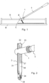
- Figure 1 shows the cutting device of the invention mounted by means of a horizontal shaft (E) of rotation on a runner (C) that can be moved along longitudinal guides (G) of a manual ceramic-cutting machine.
- Figure 2 shows the cutting device of the invention isolated and without the horizontal shaft (E) of rotation to simplify the drawing and wherein the support (1) for mounting the cutting tool (2) and the handle (3) for fixing and actuating the cutting tool can be observed.
- Figure 3 shows an exploded view of an exemplary embodiment of the cutting device, showing the different elements that make it up, specifically: the support (1), the cutting tool (2), the handle (3), the stem (4), a spring (5a) for pushing the stem towards a front position, and annular stop (6).
- the cutting tool (2) comprises a bar (21) provided with: a first end (22) with a ramp (23) inclined towards a front face (26) of the bar, a second end (24) carrying a cutting wheel (25) for marking a break line in the ceramic pieces and; on its front face (26) a row of recesses (27) spaced apart vertically.
- the recesses (27) have a length that coincides with the width of the front face.
- the bar (21) additionally has longitudinal channels (28) on the lateral and rear faces, shown in Figure 7 , for receiving appendages (15) defined in the vertical hole of the support (1) and their mounting in an angular position determined in said support (1).
- the support (1) comprises a vertical hole (11) for mounting the cutting tool (2) and a horizontal hole (12) with a threaded rear segment (13) for threaded mounting the annular stop (6) and the front end of the handle (3).
- the stem (4) and the spring (5a) for pushing the stem (4) are arranged in front of the annular stop (6).
- the stem (4) comprises: a rear end (41) facing the front end of the handle (3) and a front end provided with a projection (42), complementary and couplable to any of the recesses (27) on the front face (26) of the bar of the cutting tool.
- the bar (21) of the cutting tool is accommodated through the vertical hole (11); acting against the front face (26) of said bar (21) the stem (4) that is accommodated in the horizontal hole (12) of the support (1) capable of longitudinal movement and uncapable of rotation and with the intermediate thickening (43) facing a front stop (14) of the support (1); said stem (4) being pushed in the forward direction by the spring (5a).
- the stem has lateral planes (44) parallel to other lateral planes (16) represented in Figure 3 and defined in a hole of the support (1) that connects the horizontal hole (12) with the vertical hole (11) and through which said stem (4) accesses the interior of the vertical hole (11) to act with its front end against the front face (26) of the cutting tool (2).
- the spring (5a) for pushing the stem (4) is mounted around said stem (4) and comprises: a front end that acts against the rear surface of the intermediate thickening (43) of the stem and a front end that acts against a front surface of the annular stop (6).
- the threaded mounting of the annular stop (6) in the support (1) that allows its position to be changed and consequently the push force transmitted by the spring (5a) to the stem (4) in the forward direction.
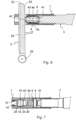
- Figures 6 and 7 show the device of the invention in a locking position of the cutting tool (2).
- the handle (3) that is threaded mounted into the support (1) acts with its front end against the rear end (41) of the stem, preventing its backward movement and ensuring that the projection (42) remains accommodated in one of the recesses (27) preventing any vertical movement of the cutting tool.
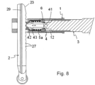
- the handle (3) In the unlocked position of the cutting tool (2), shown in Figure 8 , the handle (3) is spaced apart from the rear end (41) of the stem (4), which allows said stem (4) to perform alternate forward and backward movements.
- the stem (4) When the cutting tool is moved vertically to modify its position in height, the stem (4) performs forward and backward movements, as its projection (42) comes out of a recess (27) in the bar of the cutting tool and is accommodated in the following recess (27).
- the function of the inclined ramp (23), defined at the first end (22) of the bar (21), is to facilitate the initial assembly of the cutting tool in the vertical hole (11) of the support (1), through its progressive actuation against the front end of the stem (4) and the initial backward movement of said stem overcoming the push force of the spring (5a).
- the spring (5b) accommodated in the horizontal hole (12) of the support (1), moves the stem (4) towards a rear position for releasing the cutting tool (2), shown in Figure 9 .
Landscapes
- Engineering & Computer Science (AREA)
- Mining & Mineral Resources (AREA)
- Mechanical Engineering (AREA)
- Processing Of Stones Or Stones Resemblance Materials (AREA)
Abstract
Description
- The present invention can be used in manual machines for cutting ceramic pieces, such as slabs, tiles and the like.
- Manual machines for cutting ceramic pieces are currently known, which comprise a base for supporting the piece to be cut; and longitudinal guides on which a longitudinally movable runner is mounted and which, in turn, receives a cutting device capable of rotating about a horizontal shaft, perpendicular to said guides.
- Said device comprises a support provided with a vertical hole for mounting a cutting tool and a horizontal threaded hole that receives a handle for fixing the cutting tool and for actuating same both in the rotation motion and the longitudinal movement.
- The cutting tool comprises a bar provided with a first end that is inserted into the vertical hole of the support and a second end that receives a cutting wheel for marking a break line on the ceramic pieces.
- The bar of the cutting tools, generally having a circular cross-section, has a smooth front face, and at least one longitudinal, lateral or rear slot, which receives inside a respective anti-rotation appendage defined in the vertical hole of the support when the cutting tool is mounted on the support.
- In
patent ES 2 365 909 T3 - The applicant has found that these cutting devices exhibit a number of drawbacks related to the mounting of the cutting tool on the support and to the immobilisation of said cutting tool in the mounting position.
- Another drawback is that during mounting, the cutting tool must be placed at a suitable height so that when the handle, which acts as a lever, is lowered, the cutting wheel makes contact with the ceramic piece to be cut. During said mounting, the user must hold the cutting tool with one hand and rotate the handle with the other hand so that it is threaded mounted into the horizontal hole of the support and presses with its front end the flat front face of the bar of the cutting tool.
- Once tightening is carried out, it must be checked that the cutting tool is at the appropriate height; otherwise, the handle must be loosened while holding the cutting tool with the hand so that it is not dropped, since the pressure of the handle has been released, and reposition it intuitively at a different height; repeating these operations of loosening the handle, repositioning the cutting tool and tightening the handle, every time the height position of the cutting tool is to be modified, while holding the tool with the hand. This operation is slow and cumbersome.
- Another drawback is that once the cutting tool is tightened with the handle, a slight involuntary rotation of the handle in the direction of loosening can occur during the handling of the cutting machine, with the consequent reduction in the tightening force of the cutting tool by means of the handle and the involuntary change of the height position of said cutting tool. This change in position of the cutting tool occurs when the cutting wheel is pressed against the ceramic piece to mark the cutting line on said ceramic piece.
- Therefore, the technical problem that arises is the development of a cutting device for manual ceramic-cutting machines, which facilitates the mounting, change of position and fixation of the cutting tool with respect to the support incapable of slipping.
- The cutting device for ceramic-cutting machines object of this invention exhibits a number of technical features that provide a series of advantages with respect to the prior art; specifically:
- It allows the height position of the cutting tool to be modified in a controlled manner, placing it in a series of consecutive and predetermined positions.
- It prevents the cutting tool from slipping in an upward direction with respect to the support when the cutting wheel is pressed against the ceramic piece, so that said cutting tool maintains its position in height even though the tightening force applied thereto is reduced in the transversal direction.
- The cutting tool is not required to be manually held, to prevent same from being dropped, when the handle is loosened to change the position in height of the cutting tool.
- This cutting device for manual ceramic-cutting machines is of the type described in the preamble of the main claim and comprises a support provided with: a horizontal hole with at least one threaded rear segment that receives a handle for fixing and actuating the cutting tool, and a vertical hole that receives a cutting tool, which comprises a bar provided with: a first end accommodated through the vertical hole of the support, a second end carrying a cutting wheel for marking a break line in the ceramic pieces to be cut, and a front face facing the aforementioned horizontal hole of the support.
- In accordance with the invention, in order to achieve the proposed objectives, this cutting device comprises a stem accommodated in the horizontal hole of the support capable of movement between: a front position for locking the cutting tool, wherein the front end of said stem is accommodated in said vertical hole, and a rear position for releasing the cutting tool.
- According to the invention, the bar of the cutting tool comprises on its front face at least one row of recesses spaced apart vertically, and the stem comprises at its front end at least one projection which, in the front position for locking the cutting tool by means of the stem is accommodated in one of the recesses of the front face of the bar of the cutting tool.
- Said stem comprises a rear end facing a front end of the handle. Said handle is mounted on the support capable of movement between: a rear position in which said handle is spaced apart from the rear end of the stem and allows its backward movement; and a front position in which said handle acts against the rear end of the stem, preventing its backward movement and fixing same in the front position for locking the cutting tool.
- The bar of the cutting tool comprises at its first end a ramp, inclined towards its front face, the function of which is to facilitate its insertion into the vertical hole of the support, acting against the front end of the stem and causing its backward movement.
- In the front locking position, the projection defined at the front end of the stem is accommodated in one of the recesses in the bar of the cutting tool, preventing said cutting tool from slipping and changing the position in height when pressing the cutting wheel against the ceramic piece to be cut, even if the tightening force of the stem against the bar of the cutting tool is small.
- To lock the cutting tool at the desired height with respect to the support, it is enough to thread the handle into the support until its front end acts against the rear end of the stem, keeping it in the front locking position, uncapable of backward movement.
- According to the invention, the stem comprises an intermediate thickening arranged between a front stop of the support and an annular stop, having adjustable position, threaded mounted on the rear threaded segment of the support.
- In one embodiment of the invention, the device comprises inside the horizontal hole a spring for pushing the stem towards the front position for locking the cutting tool, said stem exerting continuous pressure against the front face of said bar.
- This push spring is mounted between the intermediate thickening of the stem and annular stop threaded mounted in the rear threaded segment of the support.
- To change the height position of the cutting tool, it is sufficient to loosen the handle so that it moves towards the rear area and move the cutting tool vertically, since said spring maintains the pressure against the bar of the cutting tool and describes alternative forward and backward movements as its front projection jumps through the successive frontal recesses of the bar of the cutting tool.
- During this change in height, the same push of the stem, by the action of the spring, holds the cutting tool making manual holding unnecessary.
- In a variant embodiment of the invention, the device comprises, inside the horizontal hole of the support, a spring for pushing the stem towards the rear position for releasing the cutting tool; being required in this case, by means of the handle, to move the stem towards the front position in order to hold and lock the cutting tool with respect to the support.
- In this embodiment, the spring for pushing the stem towards the rear position is mounted between the front stop of the support and the intermediate thickening of the stem.
- Regardless of the pushing direction of the spring, the annular stop mounted on the rear threaded segment of the horizontal hole of the support comprises an internal hole for longitudinal guidance of the rear end of the stem.
- As a complement to the description provided herein, and for the purpose of helping to make the features of the invention more readily understandable, the present specification is accompanied by a set of drawings which, by way of illustration and not limitation, represent the following:
-
Figure 1 shows a manual ceramic-cutting machine, carrying the cutting device object of the invention. -
Figure 2 shows a perspective view of the cutting device of the invention in which the rotation shaft of the support with respect to the runner for longitudinal movement on the guides of the cutting machine has been removed. -
Figure 3 shows an exploded elevation view of the cutting device of the invention provided with a spring for pushing the stem in the forward direction and cross-sectioned by a vertical plane, with the exception of the cutting tool. -
Figure 4 shows a perspective view of an exemplary embodiment of the cutting tool. -
Figure 5 shows a perspective view of an exemplary embodiment of the stem. -
Figure 6 shows an elevation view of the cutting device ofFigure 3 in mounted position, vertically cross-sectioned, and with the handle and stem in the front position for locking the cutting tool. -
Figure 7 corresponds to a plan view of the cutting device, with the support cross-sectioned by a horizontal plane, and with the stem and the handle in the same front position ofFigure 6 . -
Figure 8 shows a view similar toFigure 6 , with the handle in a rear position, in which it allows an alternative forward and backward movement of the stem, and the change of position in height of the cutting tool. -
Figure 9 shows an elevation view of a variant embodiment of the cutting device, which comprises a spring in the horizontal hole that moves the stem towards a rear position for releasing the cutting tool, and in which the stem has been represented in said rear position. -
Figure 10 shows a view similar tofigure 9 , with the stem and the handle in a front position for locking the cutting tool. -
Figure 1 shows the cutting device of the invention mounted by means of a horizontal shaft (E) of rotation on a runner (C) that can be moved along longitudinal guides (G) of a manual ceramic-cutting machine. -
Figure 2 shows the cutting device of the invention isolated and without the horizontal shaft (E) of rotation to simplify the drawing and wherein the support (1) for mounting the cutting tool (2) and the handle (3) for fixing and actuating the cutting tool can be observed. -
Figure 3 shows an exploded view of an exemplary embodiment of the cutting device, showing the different elements that make it up, specifically: the support (1), the cutting tool (2), the handle (3), the stem (4), a spring (5a) for pushing the stem towards a front position, and annular stop (6). - As can be seen in greater detail in
Figure 4 , the cutting tool (2) comprises a bar (21) provided with: a first end (22) with a ramp (23) inclined towards a front face (26) of the bar, a second end (24) carrying a cutting wheel (25) for marking a break line in the ceramic pieces and; on its front face (26) a row of recesses (27) spaced apart vertically. - In this specific embodiment, the recesses (27) have a length that coincides with the width of the front face. The bar (21) additionally has longitudinal channels (28) on the lateral and rear faces, shown in
Figure 7 , for receiving appendages (15) defined in the vertical hole of the support (1) and their mounting in an angular position determined in said support (1). - As shown in
Figure 3 , the support (1) comprises a vertical hole (11) for mounting the cutting tool (2) and a horizontal hole (12) with a threaded rear segment (13) for threaded mounting the annular stop (6) and the front end of the handle (3). - The stem (4) and the spring (5a) for pushing the stem (4) are arranged in front of the annular stop (6).
- The stem (4) comprises: a rear end (41) facing the front end of the handle (3) and a front end provided with a projection (42), complementary and couplable to any of the recesses (27) on the front face (26) of the bar of the cutting tool.
- In the mounting position of the device, shown in
figures 6 to 8 , the bar (21) of the cutting tool is accommodated through the vertical hole (11); acting against the front face (26) of said bar (21) the stem (4) that is accommodated in the horizontal hole (12) of the support (1) capable of longitudinal movement and uncapable of rotation and with the intermediate thickening (43) facing a front stop (14) of the support (1); said stem (4) being pushed in the forward direction by the spring (5a). - To prevent its rotation inside the support (1), the stem has lateral planes (44) parallel to other lateral planes (16) represented in
Figure 3 and defined in a hole of the support (1) that connects the horizontal hole (12) with the vertical hole (11) and through which said stem (4) accesses the interior of the vertical hole (11) to act with its front end against the front face (26) of the cutting tool (2). - In said mounting position, the rear end (41) of the stem is mounted through the interior hole of the annular stop (6).
- The spring (5a) for pushing the stem (4) is mounted around said stem (4) and comprises: a front end that acts against the rear surface of the intermediate thickening (43) of the stem and a front end that acts against a front surface of the annular stop (6). The threaded mounting of the annular stop (6) in the support (1) that allows its position to be changed and consequently the push force transmitted by the spring (5a) to the stem (4) in the forward direction.
-
Figures 6 and 7 show the device of the invention in a locking position of the cutting tool (2). In said locked position, the handle (3) that is threaded mounted into the support (1) acts with its front end against the rear end (41) of the stem, preventing its backward movement and ensuring that the projection (42) remains accommodated in one of the recesses (27) preventing any vertical movement of the cutting tool. - In the unlocked position of the cutting tool (2), shown in
Figure 8 , the handle (3) is spaced apart from the rear end (41) of the stem (4), which allows said stem (4) to perform alternate forward and backward movements. - In this unlocked position, the front end of the stem (4) acts, due to the push force of the spring (5a), against the front face (26), making it necessary to hold the cutting tool with the hand while its position in height is adjusted.
- When the cutting tool is moved vertically to modify its position in height, the stem (4) performs forward and backward movements, as its projection (42) comes out of a recess (27) in the bar of the cutting tool and is accommodated in the following recess (27).
- The function of the inclined ramp (23), defined at the first end (22) of the bar (21), is to facilitate the initial assembly of the cutting tool in the vertical hole (11) of the support (1), through its progressive actuation against the front end of the stem (4) and the initial backward movement of said stem overcoming the push force of the spring (5a).
- In the embodiment variant shown in
figures 9 and 10 , the spring (5b), accommodated in the horizontal hole (12) of the support (1), moves the stem (4) towards a rear position for releasing the cutting tool (2), shown inFigure 9 . - As shown in
Figure 10 , for the fixation of the cutting tool (2) it is enough to move the stem (4) by means of the handle (3) towards the front locking position. - Having sufficiently described the nature of the invention, in addition to a preferred exemplary embodiment, it is hereby stated for the relevant purposes that the materials, shape, size and layout of the described elements may be modified, provided that it does not imply altering the essential features of the invention claimed below.
Claims (9)
- A cutting device for manual ceramic-cutting machines, comprising a support (1) provided with a horizontal hole (12) with at least one threaded rear segment (13) that receives a handle (3) and a vertical hole (11) that receives a cutting tool (2), which comprises a bar (21) provided with a first end (22) accommodated through the vertical hole (11) of the support (1), a second end (24) carrying a cutting wheel (25) for marking a break line in the ceramic pieces to be cut and a front face (26) facing the horizontal hole (12) of the support (1); characterised in that it comprises a stem (4) accommodated in the horizontal hole (12) of the support (1) capable of longitudinal movement between: a front position for locking the cutting tool (2) and a rear position for releasing the cutting tool; the bar (21) of the cutting tool comprises on its front face (26) at least one row of recesses (27) spaced apart vertically, and the stem (4) comprises at its front end at least one projection (42) which, in the front position for locking the cutting tool (2) by means of the stem (4), is accommodated in one of the recesses (27) of the front face (26) of the bar (21) of the cutting tool (2).
- The device, according to claim 1, characterised in that the stem (4) comprises a rear end (41) facing a front end of the handle (3), and said handle (3) is mounted on the support (1) capable of movement between: a rear position in which it allows the backward movement of the stem (4), and a front position in which said handle acts against the rear end of the stem (4) preventing its backward movement and fixing it in the front position for locking the cutting tool (2).
- The device, according to any preceding claim; characterised in that the bar (21) of the cutting tool (2) comprises at its first end (22) a ramp (23) inclined towards its front face (26).
- The device, according to claim 4, characterised in that the stem (4) comprises an intermediate thickening (43) arranged between a front stop (14) of the support (1) and an annular stop (6), with adjustable position, threaded mounted on the rear threaded segment (13) of the support (1).
- The device, according to any of claims 1 to 4, characterised in that it comprises inside the horizontal hole (12) of the support (1) a spring (5a) for pushing the stem (4) towards the front position for locking the cutting tool (2).
- The device, according to claims 4 and 5, characterised in that the spring (5a) for pushing the stem (4) towards the front position is mounted between the intermediate thickening (43) of the stem and the annular stop (6).
- The device, according to any of claims 1 to 4, characterised in that it comprises inside the horizontal hole (12) of the support (1) a spring (5b) for pushing the stem (4) towards the rear position for releasing the cutting tool (2).
- The device, according to claims 4 and 7, characterised in that the spring (5b) for pushing the stem (4) towards the rear position is mounted between the front stop (14) of the support (1) and the intermediate thickening (43) of the stem.
- The device, according to any preceding claim characterised in that the annular stop (6) comprises an interior hole for longitudinal guidance of the rear end of the stem (4).
Applications Claiming Priority (1)
| Application Number | Priority Date | Filing Date | Title |
|---|---|---|---|
| PCT/ES2021/070817 WO2023084132A1 (en) | 2021-11-12 | 2021-11-12 | Cutting device for manual ceramic-cutting machines |
Publications (4)
| Publication Number | Publication Date |
|---|---|
| EP4249195A1 true EP4249195A1 (en) | 2023-09-27 |
| EP4249195A4 EP4249195A4 (en) | 2024-09-04 |
| EP4249195B1 EP4249195B1 (en) | 2025-05-28 |
| EP4249195C0 EP4249195C0 (en) | 2025-05-28 |
Family
ID=86335135
Family Applications (1)
| Application Number | Title | Priority Date | Filing Date |
|---|---|---|---|
| EP21963892.1A Active EP4249195B1 (en) | 2021-11-12 | 2021-11-12 | Cutting device for manual ceramic-cutting machines |
Country Status (10)
| Country | Link |
|---|---|
| US (1) | US12502807B2 (en) |
| EP (1) | EP4249195B1 (en) |
| CN (1) | CN117412845A (en) |
| CA (1) | CA3206127A1 (en) |
| CO (1) | CO2023008473A2 (en) |
| ES (1) | ES3034240T3 (en) |
| MX (1) | MX2023007490A (en) |
| PE (1) | PE20240473A1 (en) |
| PL (1) | PL4249195T3 (en) |
| WO (1) | WO2023084132A1 (en) |
Families Citing this family (2)
| Publication number | Priority date | Publication date | Assignee | Title |
|---|---|---|---|---|
| PE20240473A1 (en) * | 2021-11-12 | 2024-03-13 | Boada Germans Sa | CUTTING DEVICE FOR MANUAL CERAMIC CUTTING MACHINES |
| CN117425552A (en) * | 2021-11-12 | 2024-01-19 | 赫尔曼斯·博阿达股份有限公司 | Cutting device for manual ceramic cutters |
Family Cites Families (41)
| Publication number | Priority date | Publication date | Assignee | Title |
|---|---|---|---|---|
| US185004A (en) * | 1876-12-05 | Improvement in adjustable spittoon-brackets | ||
| US1179706A (en) * | 1915-04-12 | 1916-04-18 | Smith & Hemenway Company | Circular glass-cutter. |
| US1579995A (en) * | 1925-03-16 | 1926-04-06 | Richard J Aubuchont | Cutting or scoring machine |
| US1750718A (en) * | 1927-09-16 | 1930-03-18 | Hobbs Mfg Company | Scoring wheel |
| US1995741A (en) * | 1931-07-27 | 1935-03-26 | Samuel I Granite | Tile cutter and breaker |
| US2529735A (en) * | 1946-03-20 | 1950-11-14 | Martin Harry | Glass cutter |
| US2582078A (en) * | 1951-01-30 | 1952-01-08 | Solum Thorsten | Glass cutting apparatus |
| US2629174A (en) * | 1951-09-28 | 1953-02-24 | Domenic R Corrado | Glass cutting gauge and breaker |
| US3280677A (en) * | 1965-10-13 | 1966-10-25 | Glaces De Boussois | Apparatus for cutting sheet glass |
| US3399586A (en) * | 1966-07-11 | 1968-09-03 | Fletcher Terry Co | Glass cutting head |
| US3459078A (en) * | 1966-11-17 | 1969-08-05 | Black James | Slitting and scoring apparatus |
| US4165854A (en) * | 1978-03-29 | 1979-08-28 | Cramer Industries, Inc. | Eccentric pawl for chair locking device |
| US4228711A (en) * | 1979-05-17 | 1980-10-21 | The Fletcher-Terry Company | Self-castering glass cutter and compensating bi-directional head |
| US4672874A (en) * | 1984-11-26 | 1987-06-16 | Paul Gach | Glass scoring assembly |
| ES295592Y (en) * | 1986-06-25 | 1989-06-01 | Hermanos Boada, S.A. | FLAT CERAMIC PIECES CUTTING MACHINE |
| US5040445A (en) * | 1990-05-01 | 1991-08-20 | Liou Un Fei | Glazed tile cutter |
| AU4381593A (en) * | 1992-05-18 | 1993-12-13 | Lockformer Company, The | Glass scoring mechanism |
| EP0592345B1 (en) * | 1992-08-07 | 1998-12-02 | Germans Boada, S.A. | Machine for cutting/separating flat pieces of ceramic and the like |
| US5560274A (en) * | 1994-09-15 | 1996-10-01 | North American Tile Tool Company | Manual tile cutter |
| FR2779677B1 (en) * | 1998-06-11 | 2000-08-11 | Diamant Boart Sa | MANUAL TILE CUTTING APPARATUS |
| US6269994B1 (en) * | 1999-05-12 | 2001-08-07 | North American Tile Tool Company | Manual tile cutter |
| CN2383650Y (en) * | 1999-08-05 | 2000-06-21 | 烟台梅卡尔空气压缩机有限公司 | Floor tile cutter |
| ES1047002Y (en) | 2000-08-02 | 2001-07-16 | Boada Germans Sa | IMPROVEMENTS INTRODUCED IN CERAMIC CUTTERS. |
| ES2179777B1 (en) * | 2001-05-14 | 2003-12-16 | Boada Germans Sa | CERAMIC MANUAL CUTTER |
| DE10243289A1 (en) * | 2002-09-18 | 2004-05-19 | Robert Bosch Gmbh | tool holder |
| DE10338621B4 (en) * | 2003-08-22 | 2009-02-26 | Otto Ganter Gmbh & Co. Kg Normteilefabrik | Spring loaded locking pin |
| WO2009043944A1 (en) * | 2007-10-03 | 2009-04-09 | Germans Boada, S.A. | Manual ceramics cutter |
| US20140238376A1 (en) * | 2013-02-27 | 2014-08-28 | Stanley Black & Decker, Inc. | Foldable base for tile cutter |
| ES2537224B1 (en) * | 2013-09-20 | 2016-03-09 | Bellota Herrramientas, S.A. | Adapter device for ceramic cutting machine |
| CN204281570U (en) * | 2014-12-06 | 2015-04-22 | 弗兰科瓦利亚尼 | A glass cutting head device |
| BR102015015363B1 (en) * | 2015-06-25 | 2022-10-25 | Cortag Indústria E Comércio Ltda | CUTTING TOOL FOR A CERAMIC CUTTING DEVICE, CUTTING DISK HANDLE HANDLE, CUTTING SET AND CERAMIC CUTTING DEVICE |
| CN205006982U (en) * | 2015-08-19 | 2016-02-03 | 扬州永安塑业有限公司 | Locking body of safe scalpel |
| ES2607130B1 (en) * | 2015-09-28 | 2017-11-22 | Germans Boada, S.A. | Cutting and separation device applicable to manual ceramic cutters |
| DE102016125481A1 (en) * | 2016-12-22 | 2018-06-28 | Böllhoff Verbindungstechnik GmbH | Installation tool for a wire thread insert |
| ES2677006B1 (en) * | 2017-01-26 | 2019-05-07 | Boada Germans Sa | DEVICE FOR SELF-REGULATION OF A CUTTER HEAD FOR MONO-GUIA CUTTERS |
| CN109538610A (en) * | 2018-11-21 | 2019-03-29 | 英业达科技有限公司 | Assembling device |
| CN109623025B (en) * | 2019-01-14 | 2024-12-20 | 艾默生精密工具技术(上海)有限公司 | Cutting machines for cutting tubular parts |
| CN209681289U (en) * | 2019-01-14 | 2019-11-26 | 艾默生管道工具(上海)有限公司 | Cutting machine for cutting tubular pieces |
| EP3778059A1 (en) * | 2019-08-13 | 2021-02-17 | Schleuniger AG | Tool holding device, working machine comprising the tool holding device and method for positioning a tool on a tool holding device |
| CN112157825B (en) * | 2020-10-21 | 2022-12-27 | 广州海格丽斯石英石有限公司 | Ceramic tile cutting machine |
| PE20240473A1 (en) * | 2021-11-12 | 2024-03-13 | Boada Germans Sa | CUTTING DEVICE FOR MANUAL CERAMIC CUTTING MACHINES |
-
2021
- 2021-11-12 PE PE2023001995A patent/PE20240473A1/en unknown
- 2021-11-12 EP EP21963892.1A patent/EP4249195B1/en active Active
- 2021-11-12 CN CN202180088438.8A patent/CN117412845A/en active Pending
- 2021-11-12 CA CA3206127A patent/CA3206127A1/en active Pending
- 2021-11-12 MX MX2023007490A patent/MX2023007490A/en unknown
- 2021-11-12 US US18/260,157 patent/US12502807B2/en active Active
- 2021-11-12 WO PCT/ES2021/070817 patent/WO2023084132A1/en not_active Ceased
- 2021-11-12 PL PL21963892.1T patent/PL4249195T3/en unknown
- 2021-11-12 ES ES21963892T patent/ES3034240T3/en active Active
-
2023
- 2023-06-28 CO CONC2023/0008473A patent/CO2023008473A2/en unknown
Also Published As
| Publication number | Publication date |
|---|---|
| EP4249195B1 (en) | 2025-05-28 |
| US20240066755A1 (en) | 2024-02-29 |
| CA3206127A1 (en) | 2023-05-19 |
| PL4249195T3 (en) | 2025-08-04 |
| ES3034240T3 (en) | 2025-08-14 |
| WO2023084132A1 (en) | 2023-05-19 |
| PE20240473A1 (en) | 2024-03-13 |
| CO2023008473A2 (en) | 2023-06-30 |
| EP4249195A4 (en) | 2024-09-04 |
| MX2023007490A (en) | 2023-07-03 |
| US12502807B2 (en) | 2025-12-23 |
| CN117412845A (en) | 2024-01-16 |
| EP4249195C0 (en) | 2025-05-28 |
Similar Documents
| Publication | Publication Date | Title |
|---|---|---|
| EP4249195B1 (en) | Cutting device for manual ceramic-cutting machines | |
| US5782308A (en) | Quick clamping device for at least one tool of a machine tool | |
| US6338475B1 (en) | Bar clamp | |
| US7770277B2 (en) | Universal pulling tool | |
| US8186018B2 (en) | Auxiliary handle for hand-held power tool | |
| US20050183271A1 (en) | Reciprocating saw | |
| KR910021289A (en) | Manual tool (bar clamp) | |
| KR100777331B1 (en) | Strapping machine for forming a seal between two portions of strapping material and cutting an upper layer of the strapping material | |
| US20040065387A1 (en) | Guide for workbench | |
| US20060043660A1 (en) | Bar clamp | |
| US8109494B1 (en) | Workholding apparatus having a movable jaw member | |
| CA2773634A1 (en) | Saw blade handle with replaceable blades | |
| EP4249196B1 (en) | Cutting device for manual ceramic cutters | |
| US20110239473A1 (en) | Jig Saw with Saw Blade Holder | |
| KR960004234B1 (en) | Hand drill | |
| US6848342B2 (en) | Adjustable self-locking wrench | |
| JPH02243295A (en) | Die clamping device | |
| WO2014098617A1 (en) | A clamp | |
| US20230364692A1 (en) | Clamping device for a circular saw | |
| EP1616660A1 (en) | Clamping device | |
| EP4197465B1 (en) | Surgical tools and surgical tool systems | |
| JP4063923B2 (en) | Work vice intermediate nail block | |
| JP2514745B2 (en) | Mounting device for mounting the tool | |
| WO2000003843A1 (en) | Tool with self-locking grip, interchangeable head-pieces and clamp for fastening to the work bench | |
| JPH0889038A (en) | Sheet metal seedling planting nails |
Legal Events
| Date | Code | Title | Description |
|---|---|---|---|
| STAA | Information on the status of an ep patent application or granted ep patent |
Free format text: STATUS: THE INTERNATIONAL PUBLICATION HAS BEEN MADE |
|
| PUAI | Public reference made under article 153(3) epc to a published international application that has entered the european phase |
Free format text: ORIGINAL CODE: 0009012 |
|
| STAA | Information on the status of an ep patent application or granted ep patent |
Free format text: STATUS: REQUEST FOR EXAMINATION WAS MADE |
|
| 17P | Request for examination filed |
Effective date: 20230623 |
|
| AK | Designated contracting states |
Kind code of ref document: A1 Designated state(s): AL AT BE BG CH CY CZ DE DK EE ES FI FR GB GR HR HU IE IS IT LI LT LU LV MC MK MT NL NO PL PT RO RS SE SI SK SM TR |
|
| P01 | Opt-out of the competence of the unified patent court (upc) registered |
Effective date: 20231128 |
|
| A4 | Supplementary search report drawn up and despatched |
Effective date: 20240806 |
|
| RIC1 | Information provided on ipc code assigned before grant |
Ipc: B28D 1/22 20060101ALI20240731BHEP Ipc: B28D 1/24 20060101AFI20240731BHEP |
|
| GRAP | Despatch of communication of intention to grant a patent |
Free format text: ORIGINAL CODE: EPIDOSNIGR1 |
|
| STAA | Information on the status of an ep patent application or granted ep patent |
Free format text: STATUS: GRANT OF PATENT IS INTENDED |
|
| DAV | Request for validation of the european patent (deleted) | ||
| DAX | Request for extension of the european patent (deleted) | ||
| INTG | Intention to grant announced |
Effective date: 20250210 |
|
| GRAS | Grant fee paid |
Free format text: ORIGINAL CODE: EPIDOSNIGR3 |
|
| GRAA | (expected) grant |
Free format text: ORIGINAL CODE: 0009210 |
|
| STAA | Information on the status of an ep patent application or granted ep patent |
Free format text: STATUS: THE PATENT HAS BEEN GRANTED |
|
| AK | Designated contracting states |
Kind code of ref document: B1 Designated state(s): AL AT BE BG CH CY CZ DE DK EE ES FI FR GB GR HR HU IE IS IT LI LT LU LV MC MK MT NL NO PL PT RO RS SE SI SK SM TR |
|
| REG | Reference to a national code |
Ref country code: GB Ref legal event code: FG4D |
|
| REG | Reference to a national code |
Ref country code: CH Ref legal event code: EP |
|
| REG | Reference to a national code |
Ref country code: IE Ref legal event code: FG4D Ref country code: DE Ref legal event code: R096 Ref document number: 602021031555 Country of ref document: DE |
|
| U01 | Request for unitary effect filed |
Effective date: 20250619 |
|
| U07 | Unitary effect registered |
Designated state(s): AT BE BG DE DK EE FI FR IT LT LU LV MT NL PT RO SE SI Effective date: 20250630 |
|
| P04 | Withdrawal of opt-out of the competence of the unified patent court (upc) registered |
Free format text: CASE NUMBER: APP_30559/2025 Effective date: 20250625 |
|
| REG | Reference to a national code |
Ref country code: ES Ref legal event code: FG2A Ref document number: 3034240 Country of ref document: ES Kind code of ref document: T3 Effective date: 20250814 |
|
| PG25 | Lapsed in a contracting state [announced via postgrant information from national office to epo] |
Ref country code: GR Free format text: LAPSE BECAUSE OF FAILURE TO SUBMIT A TRANSLATION OF THE DESCRIPTION OR TO PAY THE FEE WITHIN THE PRESCRIBED TIME-LIMIT Effective date: 20250829 Ref country code: NO Free format text: LAPSE BECAUSE OF FAILURE TO SUBMIT A TRANSLATION OF THE DESCRIPTION OR TO PAY THE FEE WITHIN THE PRESCRIBED TIME-LIMIT Effective date: 20250828 |
|
| PG25 | Lapsed in a contracting state [announced via postgrant information from national office to epo] |
Ref country code: HR Free format text: LAPSE BECAUSE OF FAILURE TO SUBMIT A TRANSLATION OF THE DESCRIPTION OR TO PAY THE FEE WITHIN THE PRESCRIBED TIME-LIMIT Effective date: 20250528 |
|
| PG25 | Lapsed in a contracting state [announced via postgrant information from national office to epo] |
Ref country code: RS Free format text: LAPSE BECAUSE OF FAILURE TO SUBMIT A TRANSLATION OF THE DESCRIPTION OR TO PAY THE FEE WITHIN THE PRESCRIBED TIME-LIMIT Effective date: 20250828 |
|
| U20 | Renewal fee for the european patent with unitary effect paid |
Year of fee payment: 5 Effective date: 20250918 |
|
| PG25 | Lapsed in a contracting state [announced via postgrant information from national office to epo] |
Ref country code: IS Free format text: LAPSE BECAUSE OF FAILURE TO SUBMIT A TRANSLATION OF THE DESCRIPTION OR TO PAY THE FEE WITHIN THE PRESCRIBED TIME-LIMIT Effective date: 20250928 |
|
| PGFP | Annual fee paid to national office [announced via postgrant information from national office to epo] |
Ref country code: GB Payment date: 20251127 Year of fee payment: 5 |
|
| PG25 | Lapsed in a contracting state [announced via postgrant information from national office to epo] |
Ref country code: SM Free format text: LAPSE BECAUSE OF FAILURE TO SUBMIT A TRANSLATION OF THE DESCRIPTION OR TO PAY THE FEE WITHIN THE PRESCRIBED TIME-LIMIT Effective date: 20250528 |
|
| PGFP | Annual fee paid to national office [announced via postgrant information from national office to epo] |
Ref country code: TR Payment date: 20251023 Year of fee payment: 5 |
|
| PG25 | Lapsed in a contracting state [announced via postgrant information from national office to epo] |
Ref country code: CZ Free format text: LAPSE BECAUSE OF FAILURE TO SUBMIT A TRANSLATION OF THE DESCRIPTION OR TO PAY THE FEE WITHIN THE PRESCRIBED TIME-LIMIT Effective date: 20250528 |
|
| PGFP | Annual fee paid to national office [announced via postgrant information from national office to epo] |
Ref country code: IE Payment date: 20251127 Year of fee payment: 5 |
|
| PGFP | Annual fee paid to national office [announced via postgrant information from national office to epo] |
Ref country code: PL Payment date: 20251024 Year of fee payment: 5 |
|
| PG25 | Lapsed in a contracting state [announced via postgrant information from national office to epo] |
Ref country code: SK Free format text: LAPSE BECAUSE OF FAILURE TO SUBMIT A TRANSLATION OF THE DESCRIPTION OR TO PAY THE FEE WITHIN THE PRESCRIBED TIME-LIMIT Effective date: 20250528 |
|
| PGFP | Annual fee paid to national office [announced via postgrant information from national office to epo] |
Ref country code: ES Payment date: 20251202 Year of fee payment: 5 |
|
| REG | Reference to a national code |
Ref country code: CH Ref legal event code: W10 Free format text: ST27 STATUS EVENT CODE: U-0-0-W10-W00 (AS PROVIDED BY THE NATIONAL OFFICE) Effective date: 20260204 |
|
| RAP4 | Party data changed (patent owner data changed or rights of a patent transferred) |
Owner name: RUBI TOOLS GROUP, S.A. |
|
| U1H | Name or address of the proprietor changed after the registration of the unitary effect |
Owner name: RUBI TOOLS GROUP, S.A.; ES |
|
| PLBE | No opposition filed within time limit |
Free format text: ORIGINAL CODE: 0009261 |
|
| STAA | Information on the status of an ep patent application or granted ep patent |
Free format text: STATUS: NO OPPOSITION FILED WITHIN TIME LIMIT |
|
| REG | Reference to a national code |
Ref country code: CH Ref legal event code: L10 Free format text: ST27 STATUS EVENT CODE: U-0-0-L10-L00 (AS PROVIDED BY THE NATIONAL OFFICE) Effective date: 20260409 |
|
| 26N | No opposition filed |
Effective date: 20260303 |
|
| REG | Reference to a national code |
Ref country code: CH Ref legal event code: H13 Free format text: ST27 STATUS EVENT CODE: U-0-0-H10-H13 (AS PROVIDED BY THE NATIONAL OFFICE) Effective date: 20260623 |
|
| PG25 | Lapsed in a contracting state [announced via postgrant information from national office to epo] |
Ref country code: MC Free format text: LAPSE BECAUSE OF FAILURE TO SUBMIT A TRANSLATION OF THE DESCRIPTION OR TO PAY THE FEE WITHIN THE PRESCRIBED TIME-LIMIT Effective date: 20250528 |
|
| PG25 | Lapsed in a contracting state [announced via postgrant information from national office to epo] |
Ref country code: CH Free format text: LAPSE BECAUSE OF NON-PAYMENT OF DUE FEES Effective date: 20251130 |