EP4249144A1 - Device and method for making efficient y-pipes - Google Patents
Device and method for making efficient y-pipes Download PDFInfo
- Publication number
- EP4249144A1 EP4249144A1 EP23158999.5A EP23158999A EP4249144A1 EP 4249144 A1 EP4249144 A1 EP 4249144A1 EP 23158999 A EP23158999 A EP 23158999A EP 4249144 A1 EP4249144 A1 EP 4249144A1
- Authority
- EP
- European Patent Office
- Prior art keywords
- pipe
- jaws
- punch
- holder
- piece
- Prior art date
- Legal status (The legal status is an assumption and is not a legal conclusion. Google has not performed a legal analysis and makes no representation as to the accuracy of the status listed.)
- Pending
Links
Images



Classifications
-
- B—PERFORMING OPERATIONS; TRANSPORTING
- B21—MECHANICAL METAL-WORKING WITHOUT ESSENTIALLY REMOVING MATERIAL; PUNCHING METAL
- B21D—WORKING OR PROCESSING OF SHEET METAL OR METAL TUBES, RODS OR PROFILES WITHOUT ESSENTIALLY REMOVING MATERIAL; PUNCHING METAL
- B21D7/00—Bending rods, profiles, or tubes
- B21D7/12—Bending rods, profiles, or tubes with program control
-
- B—PERFORMING OPERATIONS; TRANSPORTING
- B21—MECHANICAL METAL-WORKING WITHOUT ESSENTIALLY REMOVING MATERIAL; PUNCHING METAL
- B21C—MANUFACTURE OF METAL SHEETS, WIRE, RODS, TUBES, PROFILES OR LIKE SEMI-MANUFACTURED PRODUCTS OTHERWISE THAN BY ROLLING; AUXILIARY OPERATIONS USED IN CONNECTION WITH METAL-WORKING WITHOUT ESSENTIALLY REMOVING MATERIAL
- B21C37/00—Manufacture of metal sheets, rods, wire, tubes, profiles or like semi-manufactured products, not otherwise provided for; Manufacture of tubes of special shape
- B21C37/06—Manufacture of metal sheets, rods, wire, tubes, profiles or like semi-manufactured products, not otherwise provided for; Manufacture of tubes of special shape of tubes or metal hoses; Combined procedures for making tubes, e.g. for making multi-wall tubes
- B21C37/15—Making tubes of special shape; Making tube fittings
- B21C37/28—Making tube fittings for connecting pipes, e.g. U-pieces
- B21C37/29—Making branched pieces, e.g. T-pieces
-
- B—PERFORMING OPERATIONS; TRANSPORTING
- B21—MECHANICAL METAL-WORKING WITHOUT ESSENTIALLY REMOVING MATERIAL; PUNCHING METAL
- B21D—WORKING OR PROCESSING OF SHEET METAL OR METAL TUBES, RODS OR PROFILES WITHOUT ESSENTIALLY REMOVING MATERIAL; PUNCHING METAL
- B21D11/00—Bending not restricted to forms of material mentioned in only one of groups B21D5/00, B21D7/00, B21D9/00; Bending not provided for in groups B21D5/00 - B21D9/00; Twisting
- B21D11/10—Bending specially adapted to produce specific articles, e.g. leaf springs
-
- B—PERFORMING OPERATIONS; TRANSPORTING
- B21—MECHANICAL METAL-WORKING WITHOUT ESSENTIALLY REMOVING MATERIAL; PUNCHING METAL
- B21D—WORKING OR PROCESSING OF SHEET METAL OR METAL TUBES, RODS OR PROFILES WITHOUT ESSENTIALLY REMOVING MATERIAL; PUNCHING METAL
- B21D11/00—Bending not restricted to forms of material mentioned in only one of groups B21D5/00, B21D7/00, B21D9/00; Bending not provided for in groups B21D5/00 - B21D9/00; Twisting
- B21D11/20—Bending sheet metal, not otherwise provided for
-
- B—PERFORMING OPERATIONS; TRANSPORTING
- B21—MECHANICAL METAL-WORKING WITHOUT ESSENTIALLY REMOVING MATERIAL; PUNCHING METAL
- B21D—WORKING OR PROCESSING OF SHEET METAL OR METAL TUBES, RODS OR PROFILES WITHOUT ESSENTIALLY REMOVING MATERIAL; PUNCHING METAL
- B21D26/00—Shaping without cutting otherwise than using rigid devices or tools or yieldable or resilient pads, i.e. applying fluid pressure or magnetic forces
- B21D26/02—Shaping without cutting otherwise than using rigid devices or tools or yieldable or resilient pads, i.e. applying fluid pressure or magnetic forces by applying fluid pressure
- B21D26/033—Deforming tubular bodies
- B21D26/037—Forming branched tubes
-
- B—PERFORMING OPERATIONS; TRANSPORTING
- B21—MECHANICAL METAL-WORKING WITHOUT ESSENTIALLY REMOVING MATERIAL; PUNCHING METAL
- B21D—WORKING OR PROCESSING OF SHEET METAL OR METAL TUBES, RODS OR PROFILES WITHOUT ESSENTIALLY REMOVING MATERIAL; PUNCHING METAL
- B21D7/00—Bending rods, profiles, or tubes
- B21D7/06—Bending rods, profiles, or tubes in press brakes or between rams and anvils or abutments; Pliers with forming dies
-
- B—PERFORMING OPERATIONS; TRANSPORTING
- B21—MECHANICAL METAL-WORKING WITHOUT ESSENTIALLY REMOVING MATERIAL; PUNCHING METAL
- B21D—WORKING OR PROCESSING OF SHEET METAL OR METAL TUBES, RODS OR PROFILES WITHOUT ESSENTIALLY REMOVING MATERIAL; PUNCHING METAL
- B21D7/00—Bending rods, profiles, or tubes
- B21D7/16—Auxiliary equipment, e.g. for heating or cooling of bends
- B21D7/162—Heating equipment
-
- F—MECHANICAL ENGINEERING; LIGHTING; HEATING; WEAPONS; BLASTING
- F16—ENGINEERING ELEMENTS AND UNITS; GENERAL MEASURES FOR PRODUCING AND MAINTAINING EFFECTIVE FUNCTIONING OF MACHINES OR INSTALLATIONS; THERMAL INSULATION IN GENERAL
- F16L—PIPES; JOINTS OR FITTINGS FOR PIPES; SUPPORTS FOR PIPES, CABLES OR PROTECTIVE TUBING; MEANS FOR THERMAL INSULATION IN GENERAL
- F16L41/00—Branching pipes; Joining pipes to walls
- F16L41/02—Branch units, e.g. made in one piece, welded, riveted
- F16L41/023—Y- pieces
Definitions
- the present invention provides a device, and a method, for decreasing the vertex angle of a Y-pipe.
- Prior art methods include welding two parts together, or hydroforming.
- Hydroforming eliminates the need for welding and the consequent seams, but it results in the Y-pipe having a much larger vertex angle, as metal cannot readily be hydroformed around sharp corners.
- the present invention provides a device as set out in claim 1, and a method as set out in claim 9, for decreasing the vertex angle of a Y-pipe.
- Optional features are set out in the dependent claims.
- a device for decreasing the vertex angle of a Y-pipe comprising a first piece configured to hold the Y-pipe, the first piece comprising a holder portion and a jaws portion, the jaws portion being moveable with relation to the holder portion between at least a first configuration and a second configuration, wherein, in the first configuration the holder portion and jaws portion form a holder for the Y-pipe with the jaws portion forming a first angle, and in the second configuration the holder portion and jaws portion form a holder for the Y-pipe with the jaws portion forming a second angle which is less than the first angle; and a second piece configured to be inserted into the vertex of the Y-pipe, the second piece comprising a wedge portion and a punch portion, the wedge portion be configured to be inserted into the vertex of the Y-pipe and the punch portion having a tip and fitting at least partially within the wedge portion and being moveable with relation to the wedge portion between a retracted
- Such a device provides an easy and reliable means for creating Y-pipes having a sharp vertex without creating points of weakness in the Y-pipe, or protrusions that will disturb the flow of fluid through the Y-pipe.
- the punch portion can be swappable, such that different punch portions having different tip profiles can be used within the wedge portion. Such a feature allows for careful control over the shape of the Y-pipe vertex.
- the holder portion can be configured to only be in contact with a part of the Y-pipe that has a cylindrical shape.
- the jaws portion can be configured to only be in contact with a part of the Y-pipe having non-parallel outer surfaces.
- the holder portion and the jaws portion can be adjacent one another. Such a feature provides improved support to the Y-pipe along its length during the bending process.
- the holder portion and the jaws portion can be moveably connected to one another. Such a feature can simplify the activation of the jaws portion, producing a more consistent bend when used to bend multiple Y-pipes of the same design.
- the holder portion can be adjustable so as to be capable of accommodating Y-pipes of different diameters. Such a feature allows one device to be used on Y-pipes having a variety of diameters.
- a method for decreasing the vertex angle of a Y-pipe comprising, placing the Y-pipe into a device, the device comprising a first piece comprising a holder portion and a jaws portion, the jaws portion being moveable with relation to the holder portion between at least a first configuration and a second configuration, wherein, in the first configuration the holder portion and jaws portion form a holder for the Y-pipe with the jaws portion forming a first angle, and in the second configuration the holder portion and jaws portion form a holder for the Y-pipe with the jaws portion forming a second angle which is less than the first angle; a second piece configured to be inserted into a vertex of the Y-pipe, the second piece comprising a wedge portion and a punch portion, the wedge portion configured to be inserted into the vertex of the Y-pipe, and the punch portion having a tip and fitting at least partially within the wedge portion and being moveable with relation to the wedge portion between
- Such a method provides an easy and reliable means for creating Y-pipes having a sharp vertex without creating points of weakness in the Y-pipe, or protrusions that will disturb the flow of fluid through the Y-pipe.
- the method can further comprise the steps of retracting the punch portion, swapping the punch portion for a second punch portion with a narrower tip, moving the second punch portion into an extended position whilst the jaws of the jaws portion move to a third configuration wherein the jaws portion forms a third angle which is less than the second angle, such that the Y-pipe held between the first piece and second piece has its vertex angle further decreased.
- These optional additional steps allow for a greater range of Y-pipe vertex angles to be achieved.
- the method can be performed with the Y-pipe at ambient temperature.
- the Y-pipe can be heated prior to performing the method. Whilst it is not necessary to provide additional heating equipment in order to heat the Y-pipe prior to bending, doing so may further improve its bendability.
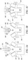
- Figure 1a shows a sectional view of a Y-pipe 100 having a vertex 120 with a vertex angle 110 equal to ⁇ 1 .
- ⁇ 1 is quite a large angle
- the vertex 120 of the Y-pipe has a large radius
- the fluid 130 flowing towards the Y-pipe junction 140 is faced with an almost perpendicular surface at the Y vertex, and so has to turn through a large angle as it splits (as illustrated by the double-headed arrow), slowing the flow of the fluid down.
- Figure 1b shows the same situation for a Y-pipe 100 with a Y vertex 120 with vertex angle 110 equal to ⁇ 2 , which is smaller than angle ⁇ 1 .
- the radius of curvature of the Y vertex 120 is commensurately smaller as a result of the sharper angle ⁇ 2 , meaning the fluid 130 does not need to turn or slow down as much when it splits at the Y-pipe junction 140.
- Figure 1c shows a sectional view of a Y-pipe 100 with a vertex angle 110 equal to ⁇ 3 at its vertex 120 which is even smaller than the angle ⁇ 2 of the Y-pipe of figure 1b .
- ⁇ 3 is even smaller than ⁇ 2 , the radius of curvature of the vertex 120 is reduced still further, and the surface area of the vertex perpendicular to the fluid flow 130 arriving at the vertex is further minimised, meaning the fluid can pass through the junction 140 even faster than for the example of figure 1b .
- Figure 2 shows a schematic of an embodiment of the device 10 of the present invention.
- the device comprises a first piece 200 and second piece 250.
- the Y-pipe 100 is placed and held in the first piece 200.
- the base 210 of the Y-pipe 100 is placed into a holder portion 220 of the first piece 200. Whilst figure 2 shows a gap between the base of the Y-pipe 100 and the holder portion 220, it is to be understood this is only shown for clarity, and that in reality the base portion would be firmly gripped and held in place by the holder portion 220.
- the holder portion 220 of the device 10 may be adjustable, such that it can be altered to accommodate different Y-pipes having different diameters.
- the holder portion can be divided into multiple pieces, the distance between which can be altered to fit different diameters of Y-pipe.
- the holder portion could have an iris-type design such that the size of the aperture within the iris can be varied to fit different diameters of Y-pipe.
- a jaws portion 240 of the first piece 200 comprising two opposed jaws 245 is brought into contact with the divergent sides 230 of the Y-pipe 100 created by the splitting of the pipe. Again, whilst the jaws 245 of the jaws portion 240 are shown spaced from the divergent sides 230 of the Y-pipe 100, in reality they will be pressed into contact with the divergent sides 230 of the Y-pipe 100.
- the jaws portion is capable of movement in relation to the holder portion between at least a first configuration and a second configuration, as shall be described.
- the second piece 250 comprises a wedge portion 260 and a punch portion 270.
- the wedge portion 260 is placed in the crook of the Y-pipe vertex 120.
- the punch portion 270 sits within the wedge portion, and is able to move relative to the wedge portion.
- the punch portion has a tip 280 at the end closest to the holder portion, which is shaped to impress a desired angular profile upon the vertex 120 of the Y-pipe 100.
- the device 10 further comprises a control system 300.
- the control system is connected to the jaws portion 240 and the punch portion 270 so as to control their movements.
- actuation means could be used in the device to move the jaws portions and punch portion, such as pneumatic or hydraulic pistons, for example. As such, the actuation means themselves have been omitted from the figures for clarity, and will not be discussed in any further detail.
- Figure 3a shows the device (with the control system 300 omitted for clarity) ready to be used, with a Y-pipe placed in the holder such that the Y-pipe is held firmly in place at the base 210 by the holder portion 220, and at the divergent sides 230 by the jaws portion 240 in a first configuration, with the wedge portion 260 in contact with, or close proximity to, the vertex 120 of the Y-pipe 100.
- the control system (not shown) activates the jaws portion 240, such that the jaws 245 pivot towards one another (as indicated by the arrows), pressing against the divergent sides 230 of the Y-pipe 100.
- the control system activates the punch portion 270, extending it from the wedge portion 260 towards the holder portion 220. In doing so, the tip 280 of the punch portion 270 is moved into the vertex 120 of the Y-pipe 100, and starts to exert pressure on the vertex.
- a Y-pipe having undergone this process can channel fluid through the junction 140 faster than it would be able to prior to the undergoing the forming process. Equally, it does not suffer from points of weakness or flow disturbance (such as weld seams) within the pipe as can be the case with Y-pipes of a similar angle formed by welding two or more pieces of pipe together.
- the process can be continued using a second punch portion 400 with a narrower tip 410 as illustrated in figures 4a to 4c .
- the jaws portion can be closed to form an even smaller vertex angle, forming a third configuration. It will be clear this process can be repeated as often as necessary, i.e. using fourth, fifth, sixth etc. configurations of the jaws portion with successive different punch portions, until the desired vertex angle is achieved.
- the device can further comprise some means of applying a heat treatment to the Y-pipe, before and/or during the bending operation and/or between bending operations in the case where the process is repeated using further punch portions with narrower tips.
- a heat treatment i.e. a heating device 420 (see figures 6a and 6b )
- a heating device 420 can be separate from the device, such that the Y-pipe is heated outside of the device and then placed in the device for bending.
- the means can be integral to the device (for example, the holder portion, jaws portion, and/or the wedge portion 260) so as to apply heat to the Y-pipe by conduction so that the Y-pipe does not need to be removed from the device during the bending process.
- Suitable heating devices will be known to the person skilled in the art. It will be appreciated that such heating devices 420 could equally be used with systems such as the examples shown in figures 2 , 3 and 4 .
- Figure 4a shows the punch portion 270 being retracted through the wedge portion 260 such that the tip 280 of the punch portion is no longer exerting pressure on or in contact with the vertex 120 of the Y-pipe 100.
- the wedge portion 260 can also be retracted from the vertex 120 at this point to facilitate the removal of the punch portion.
- the punch portion 270 can then be removed from the wedge portion, and replaced with a second punch portion 400 having a narrower tip 410 as shown in figure 4b .
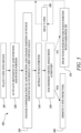
- FIG. 5 shows a flow chart illustrating a method 500 associated with the device 10 as described by example above.
- the Y-pipe is placed into the first piece 200 and second piece 250 of the device, as shown in figure 2 , ready to be processed.
- the Y-pipe may have already been heated prior to being placed into the device, or it may be heated in the device, if desired or necessary.
- the control system 300 activates the jaws portion and the punch portion in synchrony so as to apply pressure at the vertex of the Y-pipe whilst simultaneously pushing the legs of the Y-pipe together, as illustrated in figure 3b .
- the Y-pipe vertex angle is reduced, as illustrated in figure 3c .
- the punch portion can be retracted from the Y-pipe vertex as per step 540.
- the user checks to see if the desired vertex angle has been achieved. If it has, the Y-pipe can be removed from the tool for use, as per step 560. If the user wishes to reduce the Y-pipe vertex angle still further, the punch portion can be swapped out for a punch portion with a narrower tip, as per optional step 570. The user also has the option to heat the Y-pipe prior to the next stage in the process as per step 580.
- the method 500 then returns back to step 520, wherein the jaws 240 and punch 270 portions are again activated by the control system 300 in order to further reduce the Y-pipe vertex angle.
- the method can be repeated as often as necessary until the desired Y-pipe vertex angle is achieved.
- the holder portion 220 is shown as only being in contact with the cylindrical base of the Y-pipe, and not extending to the region where the Y-pipe starts to diverge, and the outer surfaces of the Y-pipe start to diverge.
- the jaws portion 240 is shown having contact only with a portion of the part of the Y-pipe where the outer surfaces are diverging, and as such are non-parallel.
- the gap shown between the holder portion and the jaws portion in figures 2 , 3 , and 4 is not essential, and that various designs of the holder portion are possible without affecting the performance of the device, or the method used to operate it.
- the holder portion and the jaws portion could be adjacent, in contact, or even moveably connected, i.e. by some sort of hinge mechanism.
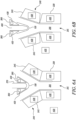
- Figures 6a and 6b show example embodiments where the holder portion 220 and jaws portion 240 are shaped so as to be adjacent to one another, providing maximum support to the Y-pipe during the bending operation.
- the support of the base of the Y-pipe is optimised during the bending process.
- the divergent section of the Y-pipe receives optimal support during the bending process.
- the holder portion 220 In order to facilitate the input of high-pressure water, the holder portion 220 must have an aperture 215 within it that allows water to pass through into the base 210, up to the vertex and along the legs formed by the split in the pipe. An example of a configuration with such an aperture is shown in figure 6 .
- the holder portion 220 with the aperture 215 could equally be used in a non-hydroforming process or device, and/or could be readily substituted into any of figures 2 , 3 , or 4 without affecting their performance or the method of using them.
Landscapes
- Engineering & Computer Science (AREA)
- Mechanical Engineering (AREA)
- General Engineering & Computer Science (AREA)
- Physics & Mathematics (AREA)
- Fluid Mechanics (AREA)
- Bending Of Plates, Rods, And Pipes (AREA)
- Shaping Metal By Deep-Drawing, Or The Like (AREA)
Abstract
Description
- The present invention provides a device, and a method, for decreasing the vertex angle of a Y-pipe.
- The design of pipes (e.g. tubes, conduits, etc.) used to transport fluids of various types (e.g. gasses and liquids) has to take into account the dynamics of the fluid. For example, it is generally desirable not to design pipes that would create excessive eddy currents, which could lead to stagnant flow in some parts of the fluid. Speed of flow is another consideration, which is particularly relevant where the pipe bends, or has a junction where flows split or combine. For example, where it is necessary to split the flow, fluid will flow faster through a Y-shaped junction than it will through a T-shaped junction, because the angle the fluid is made to turn through at the split is smaller in a Y-shaped pipe (or "Y-pipe") than a T-shaped pipe. Indeed, the smaller the angle of the Y vertex (i.e. the angle between the two legs formed by the split in the pipe), the faster the fluid can flow through the Y-pipe.
- The process for constructing a Y-pipe is, however, not without its difficulties.
- Prior art methods include welding two parts together, or hydroforming.
- The advantage of welding two parts together is that sharper angles between the legs of the Y are possible, but this comes at the cost of welding seams which are potential points of weakness and flow disturbance within the pipe.
- Hydroforming eliminates the need for welding and the consequent seams, but it results in the Y-pipe having a much larger vertex angle, as metal cannot readily be hydroformed around sharp corners.
- There is therefore a need for a means of providing a Y-pipe with a small vertex angle that does not have weld seams or at least provides a useful alternative to known Y-pipes.
- The present invention provides a device as set out in claim 1, and a method as set out in claim 9, for decreasing the vertex angle of a Y-pipe. Optional features are set out in the dependent claims.
- In a first aspect there is provided a device for decreasing the vertex angle of a Y-pipe, the device comprising a first piece configured to hold the Y-pipe, the first piece comprising a holder portion and a jaws portion, the jaws portion being moveable with relation to the holder portion between at least a first configuration and a second configuration, wherein, in the first configuration the holder portion and jaws portion form a holder for the Y-pipe with the jaws portion forming a first angle, and in the second configuration the holder portion and jaws portion form a holder for the Y-pipe with the jaws portion forming a second angle which is less than the first angle; and a second piece configured to be inserted into the vertex of the Y-pipe, the second piece comprising a wedge portion and a punch portion, the wedge portion be configured to be inserted into the vertex of the Y-pipe and the punch portion having a tip and fitting at least partially within the wedge portion and being moveable with relation to the wedge portion between a retracted position and an extended position, wherein, in the retracted position the tip of the punch portion is in a first position with respect to the wedge portion, and in the extended position the tip of the punch portion is in a second position with respect to the wedge portion, the second position being closer to the holder portion of the device than the first position; the device further comprising a control system configured to control the movement of the jaws portion and the punch portion such that the movement of the jaws portion between the first configuration and the second configuration is synchronised with the movement of the punch portion between the retracted position and the extended position such that the Y-pipe held between the first piece and second piece has its vertex angle decreased.
- Such a device provides an easy and reliable means for creating Y-pipes having a sharp vertex without creating points of weakness in the Y-pipe, or protrusions that will disturb the flow of fluid through the Y-pipe.
- The punch portion can be swappable, such that different punch portions having different tip profiles can be used within the wedge portion. Such a feature allows for careful control over the shape of the Y-pipe vertex.
- The holder portion can be configured to only be in contact with a part of the Y-pipe that has a cylindrical shape. The jaws portion can be configured to only be in contact with a part of the Y-pipe having non-parallel outer surfaces. Such features allow for Y-pipes with a greater range of divergent angles to be accommodated in the device prior to its activation, whilst still keeping the Y-pipe firmly in place.
- The holder portion and the jaws portion can be adjacent one another. Such a feature provides improved support to the Y-pipe along its length during the bending process.
- The holder portion and the jaws portion can be moveably connected to one another. Such a feature can simplify the activation of the jaws portion, producing a more consistent bend when used to bend multiple Y-pipes of the same design.
- The holder portion can be adjustable so as to be capable of accommodating Y-pipes of different diameters. Such a feature allows one device to be used on Y-pipes having a variety of diameters.
- In a second aspect, there is provided a method for decreasing the vertex angle of a Y-pipe, the method comprising, placing the Y-pipe into a device, the device comprising a first piece comprising a holder portion and a jaws portion, the jaws portion being moveable with relation to the holder portion between at least a first configuration and a second configuration, wherein, in the first configuration the holder portion and jaws portion form a holder for the Y-pipe with the jaws portion forming a first angle, and in the second configuration the holder portion and jaws portion form a holder for the Y-pipe with the jaws portion forming a second angle which is less than the first angle; a second piece configured to be inserted into a vertex of the Y-pipe, the second piece comprising a wedge portion and a punch portion, the wedge portion configured to be inserted into the vertex of the Y-pipe, and the punch portion having a tip and fitting at least partially within the wedge portion and being moveable with relation to the wedge portion between a retracted position and an extended position, wherein, in the retracted position the tip of the punch portion is in a first position with respect to the wedge portion, and in the extended position the tip of the punch portion is in a second position with respect to the wedge portion which is closer to the holder portion of the device than the first position; and a control system configured to control the movement of the jaws portion and the punch portion; using the control system to synchronise movement of the jaws portion from the first configuration to the second configuration and movement of the punch portion from the retracted position to the extended position, such that the Y-pipe held between the first piece and second piece has its vertex angle decreased.
- Such a method provides an easy and reliable means for creating Y-pipes having a sharp vertex without creating points of weakness in the Y-pipe, or protrusions that will disturb the flow of fluid through the Y-pipe.
- The method can further comprise the steps of retracting the punch portion, swapping the punch portion for a second punch portion with a narrower tip, moving the second punch portion into an extended position whilst the jaws of the jaws portion move to a third configuration wherein the jaws portion forms a third angle which is less than the second angle, such that the Y-pipe held between the first piece and second piece has its vertex angle further decreased. These optional additional steps allow for a greater range of Y-pipe vertex angles to be achieved.
- The method can be performed with the Y-pipe at ambient temperature. Alternatively, the Y-pipe can be heated prior to performing the method. Whilst it is not necessary to provide additional heating equipment in order to heat the Y-pipe prior to bending, doing so may further improve its bendability.
- The skilled person will appreciate that except where mutually exclusive, a feature described in relation to any one of the above aspects may be applied mutatis mutandis to any other aspect. Furthermore except where mutually exclusive any feature described herein may be applied to any aspect and/or combined with any other feature described herein.
- Embodiments will now be described by way of example only, with reference to the figures, in which:
-
Figure 1a is a sectional view of Y-pipe with a vertex angle θ1; -
Figure 1b is a sectional view of Y-pipe with a vertex angle θ2; -
Figure 1c is a sectional view of Y-pipe with a vertex angle θ3; -
Figure 2 is a sectional view of a schematic of an embodiment of the device of the present invention; -
Figure 3a shows the first stage of the method of the present invention; -
Figure 3b shows a second stage of the method of the present invention; -
Figure 3c shows a third stage of the method of the present invention; -
Figure 4a shows a first optional stage of the method of the present invention; -
Figure 4b shows a second optional stage of the method of the present invention; -
Figure 4c shows a third optional stage of the method of the present invention; -
Figure 5 shows a flow diagram to illustrate an embodiment of the method of the present invention; -
Figure 6a is a sectional view of a schematic of an alternative embodiment of the device of the present invention in a first configuration; and -
Figure 6b is a sectional view of a schematic of an alternative embodiment of the device of the present invention in a second configuration. - Aspects and embodiments of the present invention will now be discussed with reference to the accompanying figures. Further aspects and embodiments will be apparent to those skilled in the art.
-
Figure 1a shows a sectional view of a Y-pipe 100 having avertex 120 with avertex angle 110 equal to θ1. As θ1 is quite a large angle, and thevertex 120 of the Y-pipe has a large radius, thefluid 130 flowing towards the Y-pipe junction 140 is faced with an almost perpendicular surface at the Y vertex, and so has to turn through a large angle as it splits (as illustrated by the double-headed arrow), slowing the flow of the fluid down. -
Figure 1b shows the same situation for a Y-pipe 100 with aY vertex 120 withvertex angle 110 equal to θ2, which is smaller than angle θ1. The radius of curvature of theY vertex 120 is commensurately smaller as a result of the sharper angle θ2, meaning thefluid 130 does not need to turn or slow down as much when it splits at the Y-pipe junction 140. -
Figure 1c shows a sectional view of a Y-pipe 100 with avertex angle 110 equal to θ3 at itsvertex 120 which is even smaller than the angle θ2 of the Y-pipe offigure 1b . As θ3 is even smaller than θ2, the radius of curvature of thevertex 120 is reduced still further, and the surface area of the vertex perpendicular to thefluid flow 130 arriving at the vertex is further minimised, meaning the fluid can pass through thejunction 140 even faster than for the example offigure 1b . -
Figure 2 shows a schematic of an embodiment of thedevice 10 of the present invention. The device comprises afirst piece 200 andsecond piece 250. The Y-pipe 100 is placed and held in thefirst piece 200. Thebase 210 of the Y-pipe 100 is placed into aholder portion 220 of thefirst piece 200. Whilstfigure 2 shows a gap between the base of the Y-pipe 100 and theholder portion 220, it is to be understood this is only shown for clarity, and that in reality the base portion would be firmly gripped and held in place by theholder portion 220. Theholder portion 220 of thedevice 10 may be adjustable, such that it can be altered to accommodate different Y-pipes having different diameters. For example, the holder portion can be divided into multiple pieces, the distance between which can be altered to fit different diameters of Y-pipe. The holder portion could have an iris-type design such that the size of the aperture within the iris can be varied to fit different diameters of Y-pipe. Ajaws portion 240 of thefirst piece 200 comprising twoopposed jaws 245 is brought into contact with thedivergent sides 230 of the Y-pipe 100 created by the splitting of the pipe. Again, whilst thejaws 245 of thejaws portion 240 are shown spaced from thedivergent sides 230 of the Y-pipe 100, in reality they will be pressed into contact with thedivergent sides 230 of the Y-pipe 100. The jaws portion is capable of movement in relation to the holder portion between at least a first configuration and a second configuration, as shall be described. - The
second piece 250 comprises awedge portion 260 and apunch portion 270. Thewedge portion 260 is placed in the crook of the Y-pipe vertex 120. Thepunch portion 270 sits within the wedge portion, and is able to move relative to the wedge portion. The punch portion has atip 280 at the end closest to the holder portion, which is shaped to impress a desired angular profile upon thevertex 120 of the Y-pipe 100. - The
device 10 further comprises acontrol system 300. The control system is connected to thejaws portion 240 and thepunch portion 270 so as to control their movements. The skilled person will appreciate that a variety of actuation means could be used in the device to move the jaws portions and punch portion, such as pneumatic or hydraulic pistons, for example. As such, the actuation means themselves have been omitted from the figures for clarity, and will not be discussed in any further detail. - The action of the
device 10 and method of use will now be described.Figure 3a shows the device (with thecontrol system 300 omitted for clarity) ready to be used, with a Y-pipe placed in the holder such that the Y-pipe is held firmly in place at the base 210 by theholder portion 220, and at thedivergent sides 230 by thejaws portion 240 in a first configuration, with thewedge portion 260 in contact with, or close proximity to, thevertex 120 of the Y-pipe 100. - In
figure 3b , the control system (not shown) activates thejaws portion 240, such that thejaws 245 pivot towards one another (as indicated by the arrows), pressing against thedivergent sides 230 of the Y-pipe 100. In synchrony with the activation of the jaws portion, the control system activates thepunch portion 270, extending it from thewedge portion 260 towards theholder portion 220. In doing so, thetip 280 of thepunch portion 270 is moved into thevertex 120 of the Y-pipe 100, and starts to exert pressure on the vertex. - Finally, in
figure 3c , the combination of forces from thejaws portion 240 being moved into a second configuration and the movement of thepunch portion 270 has caused the Y-pipe to bend, decreasing thevertex angle 110 and reducing the radius of curvature of the Y-vertex (as indicated by the small arrows). This combination of forces is particularly effective as, when thedivergent sides 230 of the Y-pipe 100 are pressed together, the angle at thevertex 120 is reduced, effectively "freeing up" material in the vertex. This "freed" material can then be pushed by the tip of the punch portion to "sharpen" the vertex, reducing the radius of curvature of thevertex 120, and reducing the surface area of the vertex perpendicular to thefluid flow 130 arriving at the vertex. In use, a Y-pipe having undergone this process can channel fluid through thejunction 140 faster than it would be able to prior to the undergoing the forming process. Equally, it does not suffer from points of weakness or flow disturbance (such as weld seams) within the pipe as can be the case with Y-pipes of a similar angle formed by welding two or more pieces of pipe together. - As an optional further step, where an even greater decrease in the vertex angle of the Y-pipe is desired, the process can be continued using a
second punch portion 400 with anarrower tip 410 as illustrated infigures 4a to 4c . In this case, the jaws portion can be closed to form an even smaller vertex angle, forming a third configuration. It will be clear this process can be repeated as often as necessary, i.e. using fourth, fifth, sixth etc. configurations of the jaws portion with successive different punch portions, until the desired vertex angle is achieved. - Optionally, the device can further comprise some means of applying a heat treatment to the Y-pipe, before and/or during the bending operation and/or between bending operations in the case where the process is repeated using further punch portions with narrower tips. As is known in the art, if manipulating a material such as a metal, heating it will tend to increase its ductility. Therefore heating the Y-pipe prior to or during bending can help with the bending process. The means for applying a heat treatment, i.e. a heating device 420 (see
figures 6a and 6b ), can be separate from the device, such that the Y-pipe is heated outside of the device and then placed in the device for bending. Alternatively the means can be integral to the device (for example, the holder portion, jaws portion, and/or the wedge portion 260) so as to apply heat to the Y-pipe by conduction so that the Y-pipe does not need to be removed from the device during the bending process. Suitable heating devices will be known to the person skilled in the art. It will be appreciated thatsuch heating devices 420 could equally be used with systems such as the examples shown infigures 2 ,3 and4 . -
Figure 4a shows thepunch portion 270 being retracted through thewedge portion 260 such that thetip 280 of the punch portion is no longer exerting pressure on or in contact with thevertex 120 of the Y-pipe 100. Optionally thewedge portion 260 can also be retracted from thevertex 120 at this point to facilitate the removal of the punch portion. Thepunch portion 270 can then be removed from the wedge portion, and replaced with asecond punch portion 400 having anarrower tip 410 as shown infigure 4b . Once this is done, and the wedge portion has been put back in position if it was moved, the process of can be repeated, as shown infigure 4c , with the control system (not shown) activating thejaws portion 240 such that thejaws 245 pivot towards one another (as indicated by the arrows), pressing against thedivergent sides 230 of the Y-pipe 100, whilst in synchrony the control system activates thesecond punch portion 400, extending it from thewedge portion 260 towards theholder portion 220. Again, the combination of forces from thejaws portion 240 andsecond punch portion 400 will cause the Y-pipe to bend further, freeing more material in the vertex which is pushed further by the tip of the punch portion to further sharpen the vertex, further decreasing thevertex angle 110 and further reducing the radius of curvature of the Y-vertex (as indicated by the small arrows infigure 4c ). It will be clear to the skilled person this process of using sharper-tipped punch portions can be repeated as necessary using further configurations of the jaws portion until the desired vertex profile is arrived at. -
Figure 5 shows a flow chart illustrating amethod 500 associated with thedevice 10 as described by example above. At afirst step 510, the Y-pipe is placed into thefirst piece 200 andsecond piece 250 of the device, as shown infigure 2 , ready to be processed. The Y-pipe may have already been heated prior to being placed into the device, or it may be heated in the device, if desired or necessary. In thesecond step 520, thecontrol system 300 activates the jaws portion and the punch portion in synchrony so as to apply pressure at the vertex of the Y-pipe whilst simultaneously pushing the legs of the Y-pipe together, as illustrated infigure 3b . As a result, atstep 530, the Y-pipe vertex angle is reduced, as illustrated infigure 3c . - Once the Y-pipe vertex angle has been reduced, the punch portion can be retracted from the Y-pipe vertex as per
step 540. Atstep 550, the user checks to see if the desired vertex angle has been achieved. If it has, the Y-pipe can be removed from the tool for use, as perstep 560. If the user wishes to reduce the Y-pipe vertex angle still further, the punch portion can be swapped out for a punch portion with a narrower tip, as peroptional step 570. The user also has the option to heat the Y-pipe prior to the next stage in the process as perstep 580. Themethod 500 then returns back to step 520, wherein thejaws 240 and punch 270 portions are again activated by thecontrol system 300 in order to further reduce the Y-pipe vertex angle. The method can be repeated as often as necessary until the desired Y-pipe vertex angle is achieved. - In
figures 2 ,3 , and4 , theholder portion 220 is shown as only being in contact with the cylindrical base of the Y-pipe, and not extending to the region where the Y-pipe starts to diverge, and the outer surfaces of the Y-pipe start to diverge. Equally, thejaws portion 240 is shown having contact only with a portion of the part of the Y-pipe where the outer surfaces are diverging, and as such are non-parallel. The skilled person will appreciate that the gap shown between the holder portion and the jaws portion infigures 2 ,3 , and4 is not essential, and that various designs of the holder portion are possible without affecting the performance of the device, or the method used to operate it. For example, the holder portion and the jaws portion could be adjacent, in contact, or even moveably connected, i.e. by some sort of hinge mechanism. -
Figures 6a and 6b show example embodiments where theholder portion 220 andjaws portion 240 are shaped so as to be adjacent to one another, providing maximum support to the Y-pipe during the bending operation. By extending the holder portion along as much of the cylindrical base of the Y-pipe as possible, the support of the base of the Y-pipe is optimised during the bending process. Equally, by extending the jaws along as much of the non-parallel outer surfaces of the Y-pipe as possible, the divergent section of the Y-pipe receives optimal support during the bending process. Such a configuration, where the Y-pipe is supported at all points between theholder portion 220 and thejaws portion 245, can be used in combination with a hydroforming process as is known in the art. - During a hydroforming process, water is pushed through the Y-pipe at high pressure whilst the shape of the pipe is manipulated. If hydroforming was used in combination with the device or method of the present invention, then water would be pumped through the Y-pipe at high pressure whilst the bending of the Y-pipe is taking place. In order to facilitate the input of high-pressure water, the
holder portion 220 must have anaperture 215 within it that allows water to pass through into thebase 210, up to the vertex and along the legs formed by the split in the pipe. An example of a configuration with such an aperture is shown infigure 6 . By supporting the pipe at all points between theholder portion 220 and thejaws portion 240, i.e. by not having a gap between theholder portion 220 and thejaws portion 240, the risk of the high-pressure water causing the Y-pipe to bulge out in the gap between theholder portion 220 and jaws portion 240 (as shown for example in the configuration offigures 2 ,3 and4 ) is eliminated. It will of course be appreciated that theholder portion 220 with theaperture 215 could equally be used in a non-hydroforming process or device, and/or could be readily substituted into any offigures 2 ,3 , or4 without affecting their performance or the method of using them. - It will be understood that the invention is not limited to the embodiments above-described and various modifications and improvements can be made without departing from the concepts described herein but within the scope of the following claims.
Claims (12)
- A device (10) for decreasing the vertex angle (110) of a Y-pipe (100), the device comprising:a first piece (200) configured to hold the Y-pipe, the first piece comprising a holder portion (220) and a jaws portion (240), the jaws portion being moveable with relation to the holder portion between at least a first configuration and a second configuration, wherein, in the first configuration the holder portion and jaws portion form a holder for the Y-pipe with the jaws portion forming a first angle, and in the second configuration the holder portion and jaws portion form a holder for the Y-pipe with the jaws portion forming a second angle which is less than the first angle; anda second piece (250) configured to be inserted into the vertex (120) of the Y-pipe, the second piece comprising a wedge portion (260) and a punch portion (270), the wedge portion being configured to be inserted into the vertex of the Y-pipe and the punch portion having a tip (280) and fitting at least partially within the wedge portion and being moveable with relation to the wedge portion between a retracted position and an extended position, wherein, in the retracted position the tip of the punch portion is in a first position with respect to the wedge portion, and in the extended position the tip of the punch portion is in a second position with respect to the wedge portion, the second position being closer to the holder portion of the device than the first position;the device further comprising a control system (300) configured to control the movement of the jaws portion and the punch portion such that the movement of the jaws portion between the first configuration and the second configuration is synchronised with the movement of the punch portion between the retracted position and the extended position such that the Y-pipe held between the first piece and second piece has its vertex angle decreased.
- The device of claim 1, wherein the punch portion (270) is swappable, such that different punch portions having different tip profiles can be used within the wedge portion (260).
- The device of claim 1 or 2, wherein the holder portion (220) is configured to only be in contact with a part of the Y-pipe that has a cylindrical shape.
- The device of any preceding claim, wherein the jaws portion (240) is configured to only be in contact with a part of the Y-pipe having non-parallel outer surfaces.
- The device of any preceding claim, wherein the holder portion (220) and the jaws portion (240) are adjacent one another.
- The device of any preceding claim, wherein the holder portion (220) and the jaws portion (240) are moveably connected to one another.
- The device of any preceding claim, wherein the holder portion (220) is adjustable so as to be capable of accommodating Y-pipes of different diameters.
- The device of any preceding claim, further comprising a means (420) for applying a heat treatment to the Y-pipe.
- A method (500) for decreasing the vertex angle of a Y-pipe, the method comprising:placing the Y-pipe into a device (510), the device (10) comprising:a first piece (200) comprising a holder portion (220) and a jaws portion (240), the jaws portion being moveable with relation to the holder portion between at least a first configuration and a second configuration, wherein, in the first configuration the holder portion and jaws portion form a holder for the Y-pipe with the jaws portion forming a first angle, and in the second configuration the holder portion and jaws portion form a holder for the Y-pipe with the jaws portion forming a second angle which is less than the first angle;a second piece (250) configured to be inserted into a vertex (120) of the Y-pipe, the second piece comprising a wedge portion (260) and a punch portion (270), the wedge portion configured to be inserted into the vertex of the Y-pipe, and the punch portion having a tip (280) and fitting at least partially within the wedge portion and being moveable with relation to the wedge portion between a retracted position and an extended position, wherein, in the retracted position the tip of the punch portion is in a first position with respect to the wedge portion, and in the extended position the tip of the punch portion is in a second position with respect to the wedge portion which is closer to the holder portion of the device than the first position; anda control system (300) configured to control the movement of the jaws portion and the punch portion; andusing the control system to synchronise movement of the jaws portion from the first configuration to the second configuration and movement of the punch portion from the retracted position to the extended position (520), such that the Y-pipe held between the first piece and second piece has its vertex angle decreased (530).
- The method of claim 9, further comprising the steps of:retracting the punch portion (540);swapping the punch portion for a second punch portion with a narrower tip (570); andmoving the second punch portion into an extended position whilst the jaws of the jaws portion move to a third configuration wherein the jaws portion forms a third angle which is less than the second angle (520), such that the Y-pipe held between the first piece and second piece has its vertex angle further decreased (530).
- The method of claim 9 or 10, wherein the method is performed with the Y-pipe at ambient temperature.
- The method of claim 9 or 10, wherein the Y-pipe is heated prior to and/or whilst performing the method.
Applications Claiming Priority (1)
| Application Number | Priority Date | Filing Date | Title |
|---|---|---|---|
| GBGB2203992.9A GB202203992D0 (en) | 2022-03-22 | 2022-03-22 | Device and method for making efficient y-pipes |
Publications (1)
| Publication Number | Publication Date |
|---|---|
| EP4249144A1 true EP4249144A1 (en) | 2023-09-27 |
Family
ID=81344774
Family Applications (1)
| Application Number | Title | Priority Date | Filing Date |
|---|---|---|---|
| EP23158999.5A Pending EP4249144A1 (en) | 2022-03-22 | 2023-02-28 | Device and method for making efficient y-pipes |
Country Status (4)
| Country | Link |
|---|---|
| US (1) | US12303962B2 (en) |
| EP (1) | EP4249144A1 (en) |
| CN (1) | CN116809738A (en) |
| GB (1) | GB202203992D0 (en) |
Cited By (1)
| Publication number | Priority date | Publication date | Assignee | Title |
|---|---|---|---|---|
| CN119426918A (en) * | 2024-10-18 | 2025-02-14 | 中冶赛迪工程技术股份有限公司 | Forming technology of hot roll bending sharp angle closed steel |
Citations (5)
| Publication number | Priority date | Publication date | Assignee | Title |
|---|---|---|---|---|
| GB747524A (en) * | 1953-06-22 | 1956-04-04 | Combustion Eng | Tube bending machine |
| US2766513A (en) * | 1938-07-19 | 1956-10-16 | Comb Eugineering Inc | Method of fabricating a tubular element |
| KR100767813B1 (en) * | 2007-04-12 | 2007-10-17 | 유재영 | Manufacturing apparatus for branch pipe for fluid |
| CN106001155A (en) * | 2016-07-04 | 2016-10-12 | 上虞市舜阳管件有限公司 | Forming mold and process for stretch reducing type extruded tee joint |
| CN212760508U (en) * | 2020-08-01 | 2021-03-23 | 丰隆(新兴)制冷设备有限公司 | Make-up machine of tee bend is processed into to T venturi tube |
Family Cites Families (7)
| Publication number | Priority date | Publication date | Assignee | Title |
|---|---|---|---|---|
| AT322323B (en) * | 1972-01-04 | 1975-05-12 | Skomab Internat Maschinen Und | BENDING DEVICE FOR PUNCH KNIVES |
| US4944147A (en) * | 1986-12-08 | 1990-07-31 | Finnegan Patrick J | Apparatus for forming horse shoes |
| US4854150A (en) * | 1986-12-19 | 1989-08-08 | Rockwell International Suspension Systems Company | Method of bending and forming heated tubular workpieces |
| JP5087353B2 (en) * | 2007-09-19 | 2012-12-05 | 三菱製鋼株式会社 | Spring product production line |
| CN107876673A (en) | 2016-09-30 | 2018-04-06 | 上海昌强工业科技股份有限公司 | A kind of Y-type three way type multi-ram forging technique and mould |
| CN109513798B (en) | 2019-01-17 | 2023-05-12 | 江阴中南重工有限公司 | Integrated spherical multi-way pipe fitting and preparation method thereof |
| CN111570696B (en) | 2020-05-25 | 2021-11-05 | 上海电机学院 | Angle-adjustable large three-way die forging device and die forging method thereof |
-
2022
- 2022-03-22 GB GBGB2203992.9A patent/GB202203992D0/en not_active Ceased
-
2023
- 2023-02-28 EP EP23158999.5A patent/EP4249144A1/en active Pending
- 2023-03-16 CN CN202310259486.XA patent/CN116809738A/en active Pending
- 2023-03-16 US US18/185,040 patent/US12303962B2/en active Active
Patent Citations (5)
| Publication number | Priority date | Publication date | Assignee | Title |
|---|---|---|---|---|
| US2766513A (en) * | 1938-07-19 | 1956-10-16 | Comb Eugineering Inc | Method of fabricating a tubular element |
| GB747524A (en) * | 1953-06-22 | 1956-04-04 | Combustion Eng | Tube bending machine |
| KR100767813B1 (en) * | 2007-04-12 | 2007-10-17 | 유재영 | Manufacturing apparatus for branch pipe for fluid |
| CN106001155A (en) * | 2016-07-04 | 2016-10-12 | 上虞市舜阳管件有限公司 | Forming mold and process for stretch reducing type extruded tee joint |
| CN212760508U (en) * | 2020-08-01 | 2021-03-23 | 丰隆(新兴)制冷设备有限公司 | Make-up machine of tee bend is processed into to T venturi tube |
Cited By (1)
| Publication number | Priority date | Publication date | Assignee | Title |
|---|---|---|---|---|
| CN119426918A (en) * | 2024-10-18 | 2025-02-14 | 中冶赛迪工程技术股份有限公司 | Forming technology of hot roll bending sharp angle closed steel |
Also Published As
| Publication number | Publication date |
|---|---|
| US20230302518A1 (en) | 2023-09-28 |
| GB202203992D0 (en) | 2022-05-04 |
| US12303962B2 (en) | 2025-05-20 |
| CN116809738A (en) | 2023-09-29 |
Similar Documents
| Publication | Publication Date | Title |
|---|---|---|
| US12303962B2 (en) | Device and method for making efficient Y-pipes | |
| US9205612B2 (en) | Device for welding plastic tubes | |
| US5593708A (en) | Apparatus for bending plastic pipe | |
| Al-Qureshi et al. | Spring-back and residual stresses in bending of thin-walled aluminium tubes | |
| JP3000017B1 (en) | Pipe material bending method | |
| US20160016264A1 (en) | Barrel tank seam welder system | |
| CN118404234A (en) | Bent pipe welding device for processing metal material products | |
| ATE284765T1 (en) | METHOD AND DEVICE FOR EXPANDING A PIPE MATERIAL | |
| JP2014231068A (en) | Bending processing device | |
| KR20170107541A (en) | METHOD AND COATING APPARATUS FOR APPLYING CLADING LAYER DURING MANUFACTURE OF MULTILAYER HIGH-Duty PIPE | |
| JP2001205367A (en) | Method for bending tube end flange part | |
| JPH08267152A (en) | Method and apparatus for bending metal pipe | |
| ATE291504T1 (en) | METHOD AND DEVICE FOR INDUCTIVE BENDING OF TUBES | |
| JPH0262090B2 (en) | ||
| JP6741224B2 (en) | Joint pipe manufacturing method and processing apparatus suitable for the same | |
| KR20200083405A (en) | Pipe joint device and method for manufacturing the same | |
| JPH06238352A (en) | Method for bending metallic tube in small radius of curvature | |
| JP2019523138A (en) | Equipment for preparing pipe ends for drawing | |
| JPH11156444A (en) | Pipe bender device | |
| JP2000015350A (en) | Device for bending steel pipe and method therefor | |
| JP3860065B2 (en) | Compression bending method for metal strip | |
| JPH06269860A (en) | Bending device for metallic tube | |
| JP3660802B2 (en) | Metal tube thickening processing method | |
| JPH04220120A (en) | Method for bending pipe in minimum radius of curvature | |
| JP3335785B2 (en) | Metal tube manufacturing equipment |
Legal Events
| Date | Code | Title | Description |
|---|---|---|---|
| PUAI | Public reference made under article 153(3) epc to a published international application that has entered the european phase |
Free format text: ORIGINAL CODE: 0009012 |
|
| STAA | Information on the status of an ep patent application or granted ep patent |
Free format text: STATUS: THE APPLICATION HAS BEEN PUBLISHED |
|
| AK | Designated contracting states |
Kind code of ref document: A1 Designated state(s): AL AT BE BG CH CY CZ DE DK EE ES FI FR GB GR HR HU IE IS IT LI LT LU LV MC ME MK MT NL NO PL PT RO RS SE SI SK SM TR |
|
| STAA | Information on the status of an ep patent application or granted ep patent |
Free format text: STATUS: REQUEST FOR EXAMINATION WAS MADE |
|
| 17P | Request for examination filed |
Effective date: 20240219 |
|
| RBV | Designated contracting states (corrected) |
Designated state(s): AL AT BE BG CH CY CZ DE DK EE ES FI FR GB GR HR HU IE IS IT LI LT LU LV MC ME MK MT NL NO PL PT RO RS SE SI SK SM TR |