EP4248856A1 - Medical imaging apparatus - Google Patents
Medical imaging apparatus Download PDFInfo
- Publication number
- EP4248856A1 EP4248856A1 EP23163503.8A EP23163503A EP4248856A1 EP 4248856 A1 EP4248856 A1 EP 4248856A1 EP 23163503 A EP23163503 A EP 23163503A EP 4248856 A1 EP4248856 A1 EP 4248856A1
- Authority
- EP
- European Patent Office
- Prior art keywords
- couch
- power
- connectors
- medical imaging
- imaging apparatus
- Prior art date
- Legal status (The legal status is an assumption and is not a legal conclusion. Google has not performed a legal analysis and makes no representation as to the accuracy of the status listed.)
- Pending
Links
Images





Classifications
-
- A—HUMAN NECESSITIES
- A61—MEDICAL OR VETERINARY SCIENCE; HYGIENE
- A61B—DIAGNOSIS; SURGERY; IDENTIFICATION
- A61B5/00—Measuring for diagnostic purposes; Identification of persons
- A61B5/70—Means for positioning the patient in relation to the detecting, measuring or recording means
- A61B5/704—Tables
-
- A—HUMAN NECESSITIES
- A61—MEDICAL OR VETERINARY SCIENCE; HYGIENE
- A61B—DIAGNOSIS; SURGERY; IDENTIFICATION
- A61B5/00—Measuring for diagnostic purposes; Identification of persons
- A61B5/05—Detecting, measuring or recording for diagnosis by means of electric currents or magnetic fields; Measuring using microwaves or radio waves
- A61B5/055—Detecting, measuring or recording for diagnosis by means of electric currents or magnetic fields; Measuring using microwaves or radio waves involving electronic [EMR] or nuclear [NMR] magnetic resonance, e.g. magnetic resonance imaging
-
- A—HUMAN NECESSITIES
- A61—MEDICAL OR VETERINARY SCIENCE; HYGIENE
- A61B—DIAGNOSIS; SURGERY; IDENTIFICATION
- A61B5/00—Measuring for diagnostic purposes; Identification of persons
- A61B5/68—Arrangements of detecting, measuring or recording means, e.g. sensors, in relation to patient
- A61B5/6801—Arrangements of detecting, measuring or recording means, e.g. sensors, in relation to patient specially adapted to be attached to or worn on the body surface
- A61B5/6813—Specially adapted to be attached to a specific body part
- A61B5/6814—Head
-
- A—HUMAN NECESSITIES
- A61—MEDICAL OR VETERINARY SCIENCE; HYGIENE
- A61B—DIAGNOSIS; SURGERY; IDENTIFICATION
- A61B5/00—Measuring for diagnostic purposes; Identification of persons
- A61B5/68—Arrangements of detecting, measuring or recording means, e.g. sensors, in relation to patient
- A61B5/6801—Arrangements of detecting, measuring or recording means, e.g. sensors, in relation to patient specially adapted to be attached to or worn on the body surface
- A61B5/6813—Specially adapted to be attached to a specific body part
- A61B5/6823—Trunk, e.g., chest, back, abdomen, hip
-
- A—HUMAN NECESSITIES
- A61—MEDICAL OR VETERINARY SCIENCE; HYGIENE
- A61B—DIAGNOSIS; SURGERY; IDENTIFICATION
- A61B5/00—Measuring for diagnostic purposes; Identification of persons
- A61B5/68—Arrangements of detecting, measuring or recording means, e.g. sensors, in relation to patient
- A61B5/6801—Arrangements of detecting, measuring or recording means, e.g. sensors, in relation to patient specially adapted to be attached to or worn on the body surface
- A61B5/6813—Specially adapted to be attached to a specific body part
- A61B5/6828—Leg
-
- A—HUMAN NECESSITIES
- A61—MEDICAL OR VETERINARY SCIENCE; HYGIENE
- A61B—DIAGNOSIS; SURGERY; IDENTIFICATION
- A61B5/00—Measuring for diagnostic purposes; Identification of persons
- A61B5/70—Means for positioning the patient in relation to the detecting, measuring or recording means
-
- A—HUMAN NECESSITIES
- A61—MEDICAL OR VETERINARY SCIENCE; HYGIENE
- A61B—DIAGNOSIS; SURGERY; IDENTIFICATION
- A61B5/00—Measuring for diagnostic purposes; Identification of persons
- A61B5/72—Signal processing specially adapted for physiological signals or for diagnostic purposes
- A61B5/7225—Details of analogue processing, e.g. isolation amplifier, gain or sensitivity adjustment, filtering, baseline or drift compensation
-
- G—PHYSICS
- G01—MEASURING; TESTING
- G01R—MEASURING ELECTRIC VARIABLES; MEASURING MAGNETIC VARIABLES
- G01R33/00—Arrangements or instruments for measuring magnetic variables
- G01R33/20—Arrangements or instruments for measuring magnetic variables involving magnetic resonance
- G01R33/28—Details of apparatus provided for in groups G01R33/44 - G01R33/64
- G01R33/32—Excitation or detection systems, e.g. using radio frequency signals
- G01R33/36—Electrical details, e.g. matching or coupling of the coil to the receiver
-
- G—PHYSICS
- G01—MEASURING; TESTING
- G01R—MEASURING ELECTRIC VARIABLES; MEASURING MAGNETIC VARIABLES
- G01R33/00—Arrangements or instruments for measuring magnetic variables
- G01R33/20—Arrangements or instruments for measuring magnetic variables involving magnetic resonance
- G01R33/28—Details of apparatus provided for in groups G01R33/44 - G01R33/64
- G01R33/32—Excitation or detection systems, e.g. using radio frequency signals
- G01R33/36—Electrical details, e.g. matching or coupling of the coil to the receiver
- G01R33/3692—Electrical details, e.g. matching or coupling of the coil to the receiver involving signal transmission without using electrically conductive connections, e.g. wireless communication or optical communication of the MR signal or an auxiliary signal other than the MR signal
-
- H—ELECTRICITY
- H02—GENERATION; CONVERSION OR DISTRIBUTION OF ELECTRIC POWER
- H02J—ELECTRIC POWER NETWORKS; CIRCUIT ARRANGEMENTS OR SYSTEMS FOR SUPPLYING OR DISTRIBUTING ELECTRIC POWER; SYSTEMS FOR STORING ELECTRIC ENERGY
- H02J50/00—Circuit arrangements or systems for wireless supply or distribution of electric power
- H02J50/10—Circuit arrangements or systems for wireless supply or distribution of electric power using inductive coupling
- H02J50/12—Circuit arrangements or systems for wireless supply or distribution of electric power using inductive coupling of the resonant type
-
- H—ELECTRICITY
- H02—GENERATION; CONVERSION OR DISTRIBUTION OF ELECTRIC POWER
- H02J—ELECTRIC POWER NETWORKS; CIRCUIT ARRANGEMENTS OR SYSTEMS FOR SUPPLYING OR DISTRIBUTING ELECTRIC POWER; SYSTEMS FOR STORING ELECTRIC ENERGY
- H02J50/00—Circuit arrangements or systems for wireless supply or distribution of electric power
- H02J50/40—Circuit arrangements or systems for wireless supply or distribution of electric power using two or more transmitting or receiving devices
- H02J50/402—Circuit arrangements or systems for wireless supply or distribution of electric power using two or more transmitting or receiving devices the two or more transmitting or the two or more receiving devices being integrated in the same unit, e.g. power mats with several coils or antennas with several sub-antennas
-
- H—ELECTRICITY
- H02—GENERATION; CONVERSION OR DISTRIBUTION OF ELECTRIC POWER
- H02J—ELECTRIC POWER NETWORKS; CIRCUIT ARRANGEMENTS OR SYSTEMS FOR SUPPLYING OR DISTRIBUTING ELECTRIC POWER; SYSTEMS FOR STORING ELECTRIC ENERGY
- H02J7/00—Circuit arrangements for charging or discharging batteries or for supplying loads from batteries
- H02J7/865—Battery or charger load switching, e.g. concurrent charging and load supply
-
- A—HUMAN NECESSITIES
- A61—MEDICAL OR VETERINARY SCIENCE; HYGIENE
- A61B—DIAGNOSIS; SURGERY; IDENTIFICATION
- A61B2560/00—Constructional details of operational features of apparatus; Accessories for medical measuring apparatus
- A61B2560/02—Operational features
- A61B2560/0204—Operational features of power management
- A61B2560/0214—Operational features of power management of power generation or supply
-
- A—HUMAN NECESSITIES
- A61—MEDICAL OR VETERINARY SCIENCE; HYGIENE
- A61B—DIAGNOSIS; SURGERY; IDENTIFICATION
- A61B2562/00—Details of sensors; Constructional details of sensor housings or probes; Accessories for sensors
- A61B2562/22—Arrangements of medical sensors with cables or leads; Connectors or couplings specifically adapted for medical sensors
- A61B2562/221—Arrangements of sensors with cables or leads, e.g. cable harnesses
- A61B2562/222—Electrical cables or leads therefor, e.g. coaxial cables or ribbon cables
-
- A—HUMAN NECESSITIES
- A61—MEDICAL OR VETERINARY SCIENCE; HYGIENE
- A61B—DIAGNOSIS; SURGERY; IDENTIFICATION
- A61B2562/00—Details of sensors; Constructional details of sensor housings or probes; Accessories for sensors
- A61B2562/22—Arrangements of medical sensors with cables or leads; Connectors or couplings specifically adapted for medical sensors
- A61B2562/225—Connectors or couplings
- A61B2562/227—Sensors with electrical connectors
-
- A—HUMAN NECESSITIES
- A61—MEDICAL OR VETERINARY SCIENCE; HYGIENE
- A61B—DIAGNOSIS; SURGERY; IDENTIFICATION
- A61B5/00—Measuring for diagnostic purposes; Identification of persons
- A61B5/0002—Remote monitoring of patients using telemetry, e.g. transmission of vital signals via a communication network
- A61B5/0004—Remote monitoring of patients using telemetry, e.g. transmission of vital signals via a communication network characterised by the type of physiological signal transmitted
- A61B5/0013—Medical image data
-
- A—HUMAN NECESSITIES
- A61—MEDICAL OR VETERINARY SCIENCE; HYGIENE
- A61B—DIAGNOSIS; SURGERY; IDENTIFICATION
- A61B6/00—Apparatus or devices for radiation diagnosis; Apparatus or devices for radiation diagnosis combined with radiation therapy equipment
- A61B6/02—Arrangements for diagnosis sequentially in different planes; Stereoscopic radiation diagnosis
- A61B6/03—Computed tomography [CT]
- A61B6/032—Transmission computed tomography [CT]
-
- A—HUMAN NECESSITIES
- A61—MEDICAL OR VETERINARY SCIENCE; HYGIENE
- A61B—DIAGNOSIS; SURGERY; IDENTIFICATION
- A61B6/00—Apparatus or devices for radiation diagnosis; Apparatus or devices for radiation diagnosis combined with radiation therapy equipment
- A61B6/02—Arrangements for diagnosis sequentially in different planes; Stereoscopic radiation diagnosis
- A61B6/03—Computed tomography [CT]
- A61B6/037—Emission tomography
-
- A—HUMAN NECESSITIES
- A61—MEDICAL OR VETERINARY SCIENCE; HYGIENE
- A61B—DIAGNOSIS; SURGERY; IDENTIFICATION
- A61B6/00—Apparatus or devices for radiation diagnosis; Apparatus or devices for radiation diagnosis combined with radiation therapy equipment
- A61B6/04—Positioning of patients; Tiltable beds or the like
- A61B6/0407—Supports, e.g. tables or beds, for the body or parts of the body
-
- G—PHYSICS
- G01—MEASURING; TESTING
- G01R—MEASURING ELECTRIC VARIABLES; MEASURING MAGNETIC VARIABLES
- G01R33/00—Arrangements or instruments for measuring magnetic variables
- G01R33/20—Arrangements or instruments for measuring magnetic variables involving magnetic resonance
- G01R33/28—Details of apparatus provided for in groups G01R33/44 - G01R33/64
- G01R33/30—Sample handling arrangements, e.g. sample cells, spinning mechanisms
- G01R33/307—Sample handling arrangements, e.g. sample cells, spinning mechanisms specially adapted for moving the sample relative to the MR system, e.g. spinning mechanisms, flow cells or means for positioning the sample inside a spectrometer
Definitions
- Embodiments described herein relate generally to a medical imaging apparatus.
- the following relates to the medical imaging apparatuses for holding patients during imaging, and in one embodiment to a couch for use in any of magnetic resonance imaging (MRI), magnetic resonance spectroscopy, computed tomography (CT), and positron emission tomography (PET) .
- MRI magnetic resonance imaging
- CT computed tomography
- PET positron emission tomography
- Detachable patient couches are sometimes used with medical imaging apparatuses, including scanners for MRI, CT or PET. Having a detachable couch reduces a number of patient transfers (e.g., from a hospital bed to a stretcher to a scanner compatible stretcher and back again to the hospital bed) as well eases removal of a patient from the scanner and the associated magnetic field at the end of imaging or in an emergency. In addition, a patient may be prepared for the scan on the couch, outside of the scanning room, leading to a more efficient use of the medical imaging apparatus for busy facilities which may use multiple detachable couches in order to separate the patient preparation and scanning tasks.
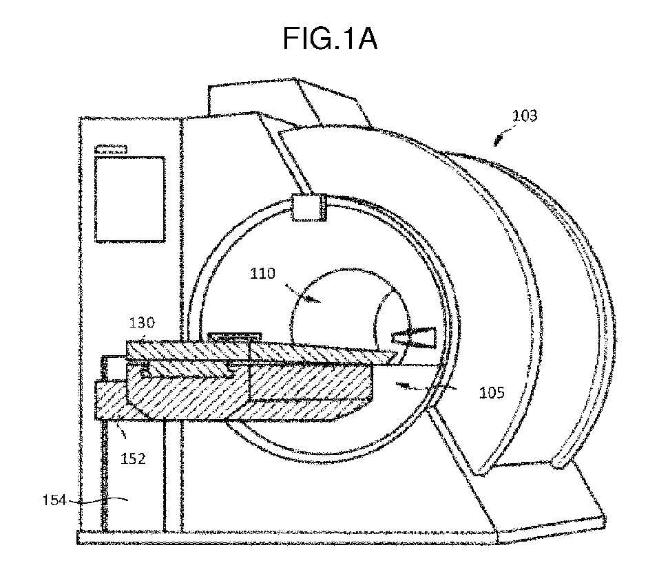
- FIG. 1A depicts a magnetic gantry 103, a bore 110, a support apparatus 105, a couch 130, a base unit 152 and a couch support unit 154. Both the base unit 152 and the couch support 154 contain gears in order to position the patient which add to the weight of the patient couch 130.
- Some MRI imagers have an imaging volume characterized by an open gap bracketed by large plates either on both sides of the patient or on top and underneath the patient.
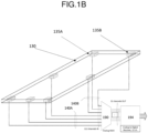
- FIG 1B illustrates internal details of a known couch 130. Shown on the couch 130 are seven coil data ports of which two (135A and135B) are labeled. As illustrated, the coil data ports carry power, control, and data, and known configurations utilize at least 16 data signals per port.
- This data traffic results in a large number of data cables (for example, more than 100 cables) containing data which is passed from the RF coils to coil data ports.
- the coil data ports e.g., 135A and 135B
- the coil data ports are then connected to an Analog Multiplexer 190 via a series of large cables 140A/140B and then to an Analog to Digital Receiver 194 that carries fewer channels away from the couch 130.
- the configuration could omit the Analog multiplexer 190 and have even more channels going into the Analog to Digital Receiver 194 but would increase the cost of the Analog to Digital Receiver 194.
- a cable is run from a control unit outside of the scanner into the bore, for example along or inside the couch 130 to extend along with the couchtop pallet into the bore of the magnetic resonance scanner.
- the cables must have a flexible arrangement that accommodates cable slack when the couchtop pallet is withdrawn onto the couch 130, and which extends to accommodate the movement of the local RF coil with the subject into the scanner bore.
- a connector may comprise a female jack, or a male plug either of which can be mounted individually or as part of a slidable electrical connector strip or sliding receptacles.
- the couch and couchtop pallet arrangement of known magnetic resonance scanners is also a complex assembly typically including a couch height adjustment mechanism and a calibrated and automated mechanical pallet translation mechanism for smoothly translating the couchtop pallet from the couch into a precise position in the magnetic resonance scanner bore for data acquisition, and for smoothly translating the pallet out of the bore and back onto the couch after the data acquisition is complete. Furthermore, integrating a power cable into this complex assembly in a manner which does not interfere with the height adjustment and pallet translation mechanisms add cost, weight, and still further complexity to the system.
- a medical imaging apparatus comprises a power supply unit; a gantry; a couch having a plurality of connectors for respectively supplying a plurality of wireless coils with power from the power supply unit, wherein the plurality of connectors do not receive data from the plurality of wireless coils; and a driving unit configured to position the couch with respect to the gantry.
- the couch may further comprise a connector for connecting to a connector of the gantry, wherein the power supply unit supplies power to the couch via the connector of the gantry and the connector of the couch.
- the power supply unit may be external to the gantry and the couch further may comprise a connector for connecting to the power supply unit external to the gantry.
- the power supply unit may be a battery housed in the couch and which is rechargeable via at least one of a power connector of the gantry and a power connection external to the gantry and the couch.
- the couch may be configured to be detachably connected to the gantry.
- the plurality of connectors may respectively supply the plurality of wireless coils with DC power.
- the plurality of connectors may respectively supply the plurality of wireless coils with DC power and a clock signal.
- the plurality of connectors may respectively supply the plurality of wireless coils with AC power.
- the plurality of connectors may be integrated into sliding receptacle.
- a first connector of the plurality of connectors may be integrated into a first sliding receptacle and a second connector of the plurality of connectors may be integrated into a second sliding receptacle independently slidable from the first sliding receptacle.
- the medical imaging apparatus may further comprise a plurality of cables for respectively connecting the plurality of connectors to the plurality of wireless coils.
- the plurality of cables may comprise a plurality of coaxial cables.
- the plurality of cables may comprise a plurality of triaxial cables.
- the plurality of cables may comprise a plurality of shielded twisted pair cables.
- the plurality of cables may be permanently affixed to the plurality of wireless coils.
- the plurality of connectors may be connected to the couch adjacent to where a patient is configured to lie while being imaged.
- the medical imaging apparatus may further comprise at least one additional connector connected to the couch underneath where a patient is configured to lie while being imaged.
- the driving unit may be configured to position the couch is integrated with the gantry.
- a medical imaging apparatus includes a power supply unit (290), a gantry (103), a couch (202) and a driving unit (152, 154).
- the couch (202) has a plurality of connectors (400A, 400B, 430) for respectively supplying a plurality of wireless coils (512, 514, 516) with power from the power supply unit (290), wherein the plurality of connectors (400A, 400B, 430) do not receive data from the plurality of wireless coils (512, 514, 516).
- the driving unit (152, 154) is configured to position the couch (202) with respect to the gantry (103).
- a number of mechanical components to position the couch within an imaging area are transferred out of the couch in order to reduce motors and motor controls and thereby reduce the weight of the couch.
- the cabling to and from the RF coils is reduced in some embodiments.
- the RF coils used to receive the RF signals (which are often disposed as local RF coils at or near the patient on the couch) can be controlled (a) wirelessly or by (b) using data communication over the power cables.
- Those RF coils may draw power from a variety of electrical connections, such as sliding receptacles or a slidable electrical connector strip placed at the edge of the couch.
- Embodiments of a couch described herein reduce the potential entanglement and the weight of longer cables and cable retractors as well as addressing safety concerns of possible RF burns from RF cabling and RF connectors close to the patient.
- the couch further may provide power to any RF coils which may be needed for the medical imaging.
- Such coils may nonetheless be referred to as “wireless” coils when they do not include data cables connected thereto (or when they may operate without data cables connected thereto in embodiments which can operate both wired and wirelessly).
- “wireless coils” as used herein may include detachably connected power lines/cables, although the wireless coils also may run on batteries that are recharged by the power connectors described herein.
- Subject matter disclosed in this "Summary" is not an exhaustive or complete disclosure of the entire scope of the technology or any embodiments thereof.
- FIG. 2 illustrates an MRI system including the detachable couch 202 according to one embodiment of this disclosure.
- the magnetic gantry 103 and the bore 110 are shown with the detachable patient couch 202 approaching the bore 110.
- the top of the couch 202 rests on the couch base 204, and a power connector 206 connected to the couch base is shown as nearly attached to the power connector 256 that receives power from a power supply unit 290.
- the couch 202 includes transport wheels 210 and rails 260 to guide the top of the couch 202 into the bore 110.
- power from the power connector 256 of the gantry 103 is connected (via power connector 206) to one or more connectors located at a top of couch 202 by cabling within the couch 202.
- power is supplied via a power cable that connectors into the table 202 that may be powered from a power supply unit outside of the room housing the gantry 103.
- the couch 202 contains a battery that is charged (e.g., via a wall socket before the couch 202 is brought into the room with the gantry 103) and that then provides power to RF coils without the couch 202 being connected to power.
- FIG. 3 illustrates an embodiment in which the power (rather than data) is supplied to one or more power connection areas 310 shown on opposite sides of the top of the couch 202.
- the couch 202 may further include a retractable power cord for keeping the powerlines to the couchtop short and out of the way.
- the connections within the power connection areas 310 are shown in greater detail in FIGS. 4A-4D .
- a couch 202 can have a different number of power connection areas 310 (e.g., one or more than two).
- the couch 202 also may include, in addition to or instead of power connection areas 310 on the sides, at least one power connection area (not shown) at one end of the couch 202.
- the couch 202 also may include a power connection area 312 that is underneath a patient when the patient is on the couch 202. Such a power connection area 312 can be used to power RF coils that are underneath the patient during imaging.
- FIG. 4A illustrates an embodiment of a power connection area 310 that utilizes a first series of fixed power connectors 400A.
- These connectors may be multi-pronged, such as, for instance +12V, GND, -12V in a three prong configuration, or, for example +12V and GND in a two prong configuration and are designed to carry power (but not data from the RF coils).
- DC power connectors carrying DC power an alternate embodiment carries low voltage AC power (e.g., 12V AC) which is converted to DC power within an RF coil using an AC-to-DC converter (e.g., a rectifier).
- the first series of fixed power connectors 400A are circular connectors into which short power cords can be inserted.
- the sides of the power connectors 400A are connected to power of a first polarity (e.g., ground, -5V or -12V, respectively) and the bottom of the power connectors 400A are connected to power of a second polarity (e.g., +5V, +5V, and +12V, respectively).
- a first polarity e.g., ground, -5V or -12V, respectively
- a second polarity e.g., +5V, +5V, and +12V, respectively.
- additional power connections can be made along the cylindrical side of the power connectors 400A such that a first part of a connector placed in the power connectors 400A contacts a first polarity, a second part of a connector placed in the power connectors 400A contacts a second polarity, and the third part of a connector placed in the power connectors 400A contacts a third polarity.
- a cylindrical audio connector that includes connections for right and left channels as well as ground (and which may even include a further connection for a microphone).
- FIG. 4B illustrates an embodiment of the power connection areas 310 that utilizes a second series of fixed DC power connectors 400B that are square.
- the sides of the power connectors 400B may be connected to a number of different polarities, such as those described above with respect to FIG. 4A . Additional sides of the power connectors 400B may be connected to connections other than power (e.g., clock).
- the power connectors 400B also may be keyed to prevent the corresponding cable from being inserted incorrectly.
- the power connectors 400B also may be connections using standard power connections, e.g., USB-A, USB-B, and USB-C style-ports and may include circuitry for negotiating the power level to be applied from the couch 202 to any connected device.
- FIG. 4C illustrates an embodiment of a power connection area 310 that uses a slidable electrical connector strip to movably provide DC power connectors 400B.
- the power connectors 400B remain grouped together but can be slid closer to either end of the couch 202.
- one side may be slid more toward the end of the couch 202 that goes into the bore while the other side may be slid more toward the end of the couch 202 that is furthest form the bore.
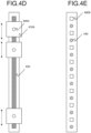
- FIG. 4D illustrates an embodiment of a power connection area 310 that uses a series of independently slidable sliding receptacle connectors 410 sliding within a channel 420 to movably provide DC power connectors 400A at various locations along one or more sides of the couch 202.
- the power connection area 310 may include more than one kind of connector, either fixed or movable.
- the power connection area may include (1) a first set of power connectors 400B for providing power at a first level and (2) a second set of connectors 430 (e.g., coaxial connectors) providing power at a second level which may include additional communicated information (e.g., a clock signal that can be broadcast to all power connectors and that is reliant to interference caused by the transmission of the B1 RF pulse).
- additional communicated information e.g., a clock signal that can be broadcast to all power connectors and that is reliant to interference caused by the transmission of the B1 RF pulse.
- the couch may further include a power cord retractor and/or power cord tensioner that removes the slack in the power cable to keep it from interfering with the motion of the couch 202.
- the couch 202 may also derive power from a battery (692 in FIG. 6 ) which may be integrated with the couch or detachable from the couch 202 in order to minimize weight.
- the battery may be part of the gantry 103, part of the couch 202, or external to both the gantry 103 and the couch 202.
- the cables between RF coils and power connectors can be any of a number of types of cables including, but not limited to, coaxial cable, triaxial cable, parallel cabling, twin axial cables, shielded twisted pair cabling, and unshielded twisted pair.
- combination cables can be made that include two of the cables listed above that are held together with an overmolding.
- the cables can be permanently attached at the couch side and detachably connected at the RF coils side, detachably attached at the couch side and permanently connected at the RF coils side, or detachably attached at the couch side and detachably connected at the RF coils side. In all configurations, the cables are designed to be as short as possible but preferably without contacting the patient.
- FIG. 5 illustrates a patient on the top of couch 202, with the top of the couch 202 positioned on top of rails 260 within the bore 110 of the scanning device.
- the patient is shown with three RF coils which include a surface coil 512, a torso coil 514, and a head coil 516.
- the coils are electrically connected to the top of couch 202 via three sliding receptacle connectors 410A, 410B, and 410C.
- the coils 512, 514, and 516 are powered through the sliding receptacle connectors 410A, 410B, and 410C but controlled by control data transferred wirelessly and image data can also be sent wirelessly to the gantry portion of the system without the data traversing the coil ports (refer to the allows 502).
- the wireless protocol which may include, for example, IEEE 802.11 Wi-Fi, Bluetooth0, Bluetooth ® LE, Near Field Communication, WirelessHART or a variety of other wireless protocols.
- the control data and image data can be transferred over the power cables of the detachable couch 202.
- a combination of RF chokes and capacitors can be used to separate the power from the data.
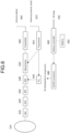
- FIG. 6 is a block diagram which illustrates the subcomponents used for transmitting the wireless image data and control data of this disclosure.
- the torso coil 514 connected to a low noise amplifier 610 which may also be a pre-amplifier.
- the low noise amplifier 610 is connected to either a Variable Gain Amplifier (VGA) or a Gain Control Amplifier (GCA) 620 and the output of the VGA/GCA 620 is passed through a band pass filter (BPF) 630.
- BPF band pass filter
- the output of the BPF 630 is detected and converted by an analog to digital converter (ADC) 640.
- the ADC 640 passes its output, a digital signal, to a data process module 650.
- the data process module 650 contains subcomponents such as one or more processors, a RAM or ROM as well as one or more universal asynchronous receiver transmitters (UARTS).
- the data process module 650 outputs the digital signal to the transmitter module 660 which outputs the image data over a transmitter antenna 662 to a receiver of the image data which may be located adjacent to the bore 110 elsewhere in the gantry 103 or remote from the gantry 103. This is also shown by the upward arrow 502 in FIG. 5 .
- FIG. 6 also shows a receive antenna 672 which may be used to receive control or clock data as shown by the downward arrows 502 in FIG. 5 .
- the data is received by the receive antenna 672 and it is passed to the transceiver 652 and to the data process module 650 before being passed to the ADC 640.
- the received control data passes directly to the PLL 642 before going to the ADC 640.
- the control data passes through the BPF 630, the VGA/GCA 620 and the LNA 610 before reaching the RF coil (torso coil 514) where the control data performs a command (such as turning the device on or off or adjusting some other imaging parameter.
- the battery subcomponents such as the power connector cable 256 as a DC plug, the battery controller 690, the DC/DC converter 680 and the distribution of power to the RF Coil components.
- This distribution may include, for example, a power connection area 310 or 312 using a slidable electrical connector strip or a power connection area 310 or 312 using sliding receptacle connectors 410.
- the power connection area 312 using an optional slidable electrical connector strip may support RF Coils which may be needed under the patient. In this configuration the RF Coils may be directly connected to the connector strip without use of additional cabling (e.g., using a connector in the underside of the RF coil that connectors directly into the power connection area 312 using the slidable electrical connector strip).
- FIG. 7 illustrates a flow diagram showing a method 700 of using the detachable couch together with RF coils wirelessly connected to an MRI system where data is transmitted wirelessly to and from the RF coils.
- Block 710 shows the step of placing the patient on the patient couch 202. This may be done with one or more patients onto multiple couches 202 remote to the gantry 103 in order to make best use of the medical imaging apparatus. In that case, one or more patients can be prepared for imaging while a previous patient is being imaged.
- Shown in block 720 is the transporting of the couch 202 on which the patient has been placed to the gantry 103. This can be done with the help of the couch base 204 and the transport wheels 210 shown in FIG. 2 .
- the couch 202 is connected to a drive unit of the gantry 103.
- This drive unit may be embedded in the couch 202 or integrated with the gantry 103.
- This drive unit may be a drive unit capable of moving the couch 202 either horizontally and/or vertically within the bore 110.
- the electricity base of the couch 202 is connected to the power supply of the gantry 103 such as shown in FIG 2 the power connectors 206 and 256.
- block 750 the electricity of the couch 202, which may carry a synchronization clock is connected to the RF coils.
- the couch 202 is positioned either horizontally or vertically within the bore 110.
- the RF coils receive control instructions wirelessly which may be, for example to initiate or change the strength or timing of the RF in the RF Coil.
- the image data is collected from the patient by using the RF Coil and in block 780 the image data is transmitted wirelessly from the RF coils to a receiver located in the gantry 103 or in another room remote from the gantry 103. This might be by use of 4G or 5G cellular, Bluetooth ® , IEEE 802.11 Wi-Fi, LoRA (registered trademark), WirelessHART, ZigBEE (registered trademark) or other wireless protocol.
- the scan control data received in block 762 is not received wirelessly but transmitted over filtered power connections which also would involve a RF Choke to separate the DC electrical power from the signal.
- the image data of block 770 may also be transmitted via the power cables.
- a synchronization clock signal may be transmitted to the RF coils over the DC power cables.
- Terminology is for the purpose of describing particular embodiments only and is not intended to be limiting of the embodiments.
- the words "preferred” and “preferably” refer to embodiments of the technology that afford certain benefits, under certain circumstances. However, other embodiments may also be preferred, under the same or other circumstances. Furthermore, the recitation of one or more preferred embodiments does not imply that other embodiments are not useful and is not intended to exclude other embodiments from the scope of the technology.
Landscapes
- Health & Medical Sciences (AREA)
- Life Sciences & Earth Sciences (AREA)
- Engineering & Computer Science (AREA)
- Physics & Mathematics (AREA)
- Surgery (AREA)
- Animal Behavior & Ethology (AREA)
- Veterinary Medicine (AREA)
- Public Health (AREA)
- Biophysics (AREA)
- Pathology (AREA)
- Biomedical Technology (AREA)
- Heart & Thoracic Surgery (AREA)
- Medical Informatics (AREA)
- Molecular Biology (AREA)
- General Health & Medical Sciences (AREA)
- Power Engineering (AREA)
- Computer Networks & Wireless Communication (AREA)
- General Physics & Mathematics (AREA)
- Condensed Matter Physics & Semiconductors (AREA)
- Nuclear Medicine, Radiotherapy & Molecular Imaging (AREA)
- Signal Processing (AREA)
- Radiology & Medical Imaging (AREA)
- Physiology (AREA)
- Psychiatry (AREA)
- Computer Vision & Pattern Recognition (AREA)
- Artificial Intelligence (AREA)
- High Energy & Nuclear Physics (AREA)
- Magnetic Resonance Imaging Apparatus (AREA)
Abstract
Description
- Embodiments described herein relate generally to a medical imaging apparatus.
- Specifically, the following relates to the medical imaging apparatuses for holding patients during imaging, and in one embodiment to a couch for use in any of magnetic resonance imaging (MRI), magnetic resonance spectroscopy, computed tomography (CT), and positron emission tomography (PET) .
- Detachable patient couches are sometimes used with medical imaging apparatuses, including scanners for MRI, CT or PET. Having a detachable couch reduces a number of patient transfers (e.g., from a hospital bed to a stretcher to a scanner compatible stretcher and back again to the hospital bed) as well eases removal of a patient from the scanner and the associated magnetic field at the end of imaging or in an emergency. In addition, a patient may be prepared for the scan on the couch, outside of the scanning room, leading to a more efficient use of the medical imaging apparatus for busy facilities which may use multiple detachable couches in order to separate the patient preparation and scanning tasks.
- A number of different shapes and forms of medical imaging apparatuses are in use, most having an annular form, with the patient being imaged in the central aperture which extends through the length of the machine. A known MRI imaging system with a corresponding couch is shown in
FIG. 1A which depicts amagnetic gantry 103, abore 110, asupport apparatus 105, acouch 130, abase unit 152 and acouch support unit 154. Both thebase unit 152 and thecouch support 154 contain gears in order to position the patient which add to the weight of thepatient couch 130. Some MRI imagers have an imaging volume characterized by an open gap bracketed by large plates either on both sides of the patient or on top and underneath the patient. Although annular imagers are shown in figures provided in this description, the presently described technology applies to medical imaging apparatuses of all types. - In magnetic resonance acquisitions, it is sometimes useful to have a local radio frequency (RF) coil disposed with or near the subject during imaging. Such proximate positioning of a local RF coil used for transmitting a magnetic resonance excitation signal, for receiving a magnetic resonance signal, or both, substantially improves radio frequency coupling between the RF coil and the subject.
FIG 1B illustrates internal details of a knowncouch 130. Shown on thecouch 130 are seven coil data ports of which two (135A and135B) are labeled. As illustrated, the coil data ports carry power, control, and data, and known configurations utilize at least 16 data signals per port. This data traffic, which includes imaging data, results in a large number of data cables (for example, more than 100 cables) containing data which is passed from the RF coils to coil data ports. The coil data ports (e.g., 135A and 135B) are then connected to anAnalog Multiplexer 190 via a series oflarge cables 140A/140B and then to an Analog toDigital Receiver 194 that carries fewer channels away from thecouch 130. Alternatively, the configuration could omit theAnalog multiplexer 190 and have even more channels going into the Analog toDigital Receiver 194 but would increase the cost of the Analog toDigital Receiver 194. - As a result, one difficulty with local RF coils is the need to separately transfer data from the coils over the
large cables 140A/140B. In a typical arrangement, a cable is run from a control unit outside of the scanner into the bore, for example along or inside thecouch 130 to extend along with the couchtop pallet into the bore of the magnetic resonance scanner. - The cables must have a flexible arrangement that accommodates cable slack when the couchtop pallet is withdrawn onto the
couch 130, and which extends to accommodate the movement of the local RF coil with the subject into the scanner bore. In addition, one patient may need multiple RF coils for different parts of their body such that more than a single power connector may be contained on the couch. A connector may comprise a female jack, or a male plug either of which can be mounted individually or as part of a slidable electrical connector strip or sliding receptacles. - The couch and couchtop pallet arrangement of known magnetic resonance scanners is also a complex assembly typically including a couch height adjustment mechanism and a calibrated and automated mechanical pallet translation mechanism for smoothly translating the couchtop pallet from the couch into a precise position in the magnetic resonance scanner bore for data acquisition, and for smoothly translating the pallet out of the bore and back onto the couch after the data acquisition is complete. Furthermore, integrating a power cable into this complex assembly in a manner which does not interfere with the height adjustment and pallet translation mechanisms add cost, weight, and still further complexity to the system.
- The above Background is intended only for general organization of topics within the present embodiment and is not intended to limit the disclosure of the present embodiment or any aspect thereof. In particular, subject matter disclosed in the "Background" may include novel technology and may not constitute a recitation of prior art.
- A medical imaging apparatus according to an aspect of the present invention comprises a power supply unit; a gantry; a couch having a plurality of connectors for respectively supplying a plurality of wireless coils with power from the power supply unit, wherein the plurality of connectors do not receive data from the plurality of wireless coils; and a driving unit configured to position the couch with respect to the gantry.
- The couch may further comprise a connector for connecting to a connector of the gantry, wherein the power supply unit supplies power to the couch via the connector of the gantry and the connector of the couch.
- The power supply unit may be external to the gantry and the couch further may comprise a connector for connecting to the power supply unit external to the gantry.
- The power supply unit may be a battery housed in the couch and which is rechargeable via at least one of a power connector of the gantry and a power connection external to the gantry and the couch.
- The couch may be configured to be detachably connected to the gantry.
- The plurality of connectors may respectively supply the plurality of wireless coils with DC power.
- The plurality of connectors may respectively supply the plurality of wireless coils with DC power and a clock signal.
- The plurality of connectors may respectively supply the plurality of wireless coils with AC power.
- The plurality of connectors may be integrated into sliding receptacle.
- A first connector of the plurality of connectors may be integrated into a first sliding receptacle and a second connector of the plurality of connectors may be integrated into a second sliding receptacle independently slidable from the first sliding receptacle.
- The medical imaging apparatus may further comprise a plurality of cables for respectively connecting the plurality of connectors to the plurality of wireless coils.
- The plurality of cables may comprise a plurality of coaxial cables.
- The plurality of cables may comprise a plurality of triaxial cables.
- The plurality of cables may comprise a plurality of shielded twisted pair cables.
- The plurality of cables may be permanently affixed to the plurality of wireless coils.
- The plurality of connectors may be connected to the couch adjacent to where a patient is configured to lie while being imaged.
- The medical imaging apparatus may further comprise at least one additional connector connected to the couch underneath where a patient is configured to lie while being imaged.
- The driving unit may be configured to position the couch is integrated with the gantry.
- A more complete appreciation of the embodiment and many of the attendant advantages thereof will be readily obtained as the same becomes better understood by reference to the following detailed description when considered in connection with the accompanying drawings, wherein:
-
FIG. 1A illustrates a known embodiment of an MRI system. -
FIG. 1B illustrates internal details of a couch associated with a known embodiment of a magnetic resonance system including large bundles of cables required to route data from various ports within the couch. -
FIG. 2 illustrates an MRI system including a detachable couch according to an embodiment. -
FIG. 3 illustrates an embodiment which generally includes power connection areas as part of a detachable couch. -
FIG. 4A illustrates an embodiment of a power connection area that utilizes a first series of fixed DC power connectors. -
FIG. 4B illustrates an embodiment of a power connection area that utilizes a second series of fixed DC power connectors. -
FIG. 4C illustrates an embodiment of a power connection area that uses a slidable electrical connector strip to movably provide DC power connectors. -
FIG. 4D illustrates an embodiment of a power connection area that uses a series of sliding receptacle connectors to movably provide DC power connectors. -
FIG. 4E illustrates an embodiment of a power connection area that utilizes a third series of connectors where the connectors are of different types for carrying different signal types/communications protocols. -
FIG. 5 illustrates a supine patient on a detachable patient couch according to one embodiment. -
FIG. 6 is a block diagram which illustrates the subcomponents used for transmitting the wireless image data and control data of this disclosure. -
FIG. 7 is a flow diagram which illustrates the method of using the detachable couch with an MRI machine and RF coils that transmit data wirelessly. - A medical imaging apparatus according to an embodiment includes a power supply unit (290), a gantry (103), a couch (202) and a driving unit (152, 154). The couch (202) has a plurality of connectors (400A, 400B, 430) for respectively supplying a plurality of wireless coils (512, 514, 516) with power from the power supply unit (290), wherein the plurality of connectors (400A, 400B, 430) do not receive data from the plurality of wireless coils (512, 514, 516). The driving unit (152, 154) is configured to position the couch (202) with respect to the gantry (103).
- Hereinafter, embodiments of a medical imaging apparatus are described in detail with reference to the drawings.
- In this disclosure, a number of mechanical components to position the couch within an imaging area (e.g., a magnetic bore) are transferred out of the couch in order to reduce motors and motor controls and thereby reduce the weight of the couch. This includes the motor and positioning hardware to control at least one of the horizontal and vertical positioning of the couch. In addition, the cabling to and from the RF coils is reduced in some embodiments. The RF coils used to receive the RF signals (which are often disposed as local RF coils at or near the patient on the couch) can be controlled (a) wirelessly or by (b) using data communication over the power cables. Those RF coils may draw power from a variety of electrical connections, such as sliding receptacles or a slidable electrical connector strip placed at the edge of the couch. Embodiments of a couch described herein reduce the potential entanglement and the weight of longer cables and cable retractors as well as addressing safety concerns of possible RF burns from RF cabling and RF connectors close to the patient.
- The couch further may provide power to any RF coils which may be needed for the medical imaging. Such coils may nonetheless be referred to as "wireless" coils when they do not include data cables connected thereto (or when they may operate without data cables connected thereto in embodiments which can operate both wired and wirelessly). Thus, "wireless coils" as used herein may include detachably connected power lines/cables, although the wireless coils also may run on batteries that are recharged by the power connectors described herein. Subject matter disclosed in this "Summary" is not an exhaustive or complete disclosure of the entire scope of the technology or any embodiments thereof.
- Referring now to the drawings, wherein like reference numerals designate identical or corresponding parts throughout the several views.
FIG. 2 illustrates an MRI system including thedetachable couch 202 according to one embodiment of this disclosure. InFIG. 2 , themagnetic gantry 103 and thebore 110 are shown with thedetachable patient couch 202 approaching thebore 110. The top of thecouch 202 rests on thecouch base 204, and apower connector 206 connected to the couch base is shown as nearly attached to thepower connector 256 that receives power from apower supply unit 290. Thecouch 202 includestransport wheels 210 andrails 260 to guide the top of thecouch 202 into thebore 110. In one embodiment, power from thepower connector 256 of thegantry 103 is connected (via power connector 206) to one or more connectors located at a top ofcouch 202 by cabling within thecouch 202. In another embodiment, power is supplied via a power cable that connectors into the table 202 that may be powered from a power supply unit outside of the room housing thegantry 103. In another embodiment, thecouch 202 contains a battery that is charged (e.g., via a wall socket before thecouch 202 is brought into the room with the gantry 103) and that then provides power to RF coils without thecouch 202 being connected to power. -
FIG. 3 illustrates an embodiment in which the power (rather than data) is supplied to one or morepower connection areas 310 shown on opposite sides of the top of thecouch 202. In an embodiment where power is supplied to thecouch 202 by thepower connector 256 or via the power cable, thecouch 202 may further include a retractable power cord for keeping the powerlines to the couchtop short and out of the way. The connections within thepower connection areas 310 are shown in greater detail inFIGS. 4A-4D . Moreover, inFIG. 3 , although shown as having twopower connection areas 310, acouch 202 can have a different number of power connection areas 310 (e.g., one or more than two). Thecouch 202 also may include, in addition to or instead ofpower connection areas 310 on the sides, at least one power connection area (not shown) at one end of thecouch 202. Thecouch 202 also may include apower connection area 312 that is underneath a patient when the patient is on thecouch 202. Such apower connection area 312 can be used to power RF coils that are underneath the patient during imaging. - As shown in
FIGS. 4A-4E , a number of different configurations are possible for thepower connection areas 310.FIG. 4A illustrates an embodiment of apower connection area 310 that utilizes a first series of fixedpower connectors 400A. These connectors may be multi-pronged, such as, for instance +12V, GND, -12V in a three prong configuration, or, for example +12V and GND in a two prong configuration and are designed to carry power (but not data from the RF coils). Although described generally herein as being DC power connectors carrying DC power, an alternate embodiment carries low voltage AC power (e.g., 12V AC) which is converted to DC power within an RF coil using an AC-to-DC converter (e.g., a rectifier). In the embodiment illustrated inFIG. 4A , the first series of fixedpower connectors 400A are circular connectors into which short power cords can be inserted. In one such configuration, the sides of thepower connectors 400A are connected to power of a first polarity (e.g., ground, -5V or -12V, respectively) and the bottom of thepower connectors 400A are connected to power of a second polarity (e.g., +5V, +5V, and +12V, respectively). In yet another configuration, additional power connections can be made along the cylindrical side of thepower connectors 400A such that a first part of a connector placed in thepower connectors 400A contacts a first polarity, a second part of a connector placed in thepower connectors 400A contacts a second polarity, and the third part of a connector placed in thepower connectors 400A contacts a third polarity. Those of skill in the art will appreciate the similarity with a cylindrical audio connector that includes connections for right and left channels as well as ground (and which may even include a further connection for a microphone). - Alternatively,
FIG. 4B illustrates an embodiment of thepower connection areas 310 that utilizes a second series of fixedDC power connectors 400B that are square. In the embodiment illustrated inFIG. 4B , the sides of thepower connectors 400B may be connected to a number of different polarities, such as those described above with respect toFIG. 4A . Additional sides of thepower connectors 400B may be connected to connections other than power (e.g., clock). Thepower connectors 400B also may be keyed to prevent the corresponding cable from being inserted incorrectly. Thepower connectors 400B also may be connections using standard power connections, e.g., USB-A, USB-B, and USB-C style-ports and may include circuitry for negotiating the power level to be applied from thecouch 202 to any connected device. - In yet another embodiment,
FIG. 4C illustrates an embodiment of apower connection area 310 that uses a slidable electrical connector strip to movably provideDC power connectors 400B. In the embodiment illustrated inFIG. 4C , thepower connectors 400B remain grouped together but can be slid closer to either end of thecouch 202. In a configuration using apower connection area 310 that uses the slidable electrical connector strip on each side, one side may be slid more toward the end of thecouch 202 that goes into the bore while the other side may be slid more toward the end of thecouch 202 that is furthest form the bore. -
FIG. 4D illustrates an embodiment of apower connection area 310 that uses a series of independently slidable sliding receptacle connectors 410 sliding within achannel 420 to movably provideDC power connectors 400A at various locations along one or more sides of thecouch 202. In yet another embodiment, as shown inFIG. 4E , thepower connection area 310 may include more than one kind of connector, either fixed or movable. For example, the power connection area may include (1) a first set ofpower connectors 400B for providing power at a first level and (2) a second set of connectors 430 (e.g., coaxial connectors) providing power at a second level which may include additional communicated information (e.g., a clock signal that can be broadcast to all power connectors and that is reliant to interference caused by the transmission of the B1 RF pulse). Using the configurations ofFIGS. 4A-4E permits multiple RF coils to be inserted at multiple positions along the top of thecouch 202 with a minimum of cabling to the RF coils. In embodiments in which a power cable needs to move to accommodate motion of a power connection area, the couch may further include a power cord retractor and/or power cord tensioner that removes the slack in the power cable to keep it from interfering with the motion of thecouch 202. Thecouch 202 may also derive power from a battery (692 inFIG. 6 ) which may be integrated with the couch or detachable from thecouch 202 in order to minimize weight. The battery may be part of thegantry 103, part of thecouch 202, or external to both thegantry 103 and thecouch 202. - The cables between RF coils and power connectors can be any of a number of types of cables including, but not limited to, coaxial cable, triaxial cable, parallel cabling, twin axial cables, shielded twisted pair cabling, and unshielded twisted pair. In connections where multiple connectors are to be connected to the same RF coil; combination cables can be made that include two of the cables listed above that are held together with an overmolding. The cables can be permanently attached at the couch side and detachably connected at the RF coils side, detachably attached at the couch side and permanently connected at the RF coils side, or detachably attached at the couch side and detachably connected at the RF coils side. In all configurations, the cables are designed to be as short as possible but preferably without contacting the patient.
-
FIG. 5 illustrates a patient on the top ofcouch 202, with the top of thecouch 202 positioned on top ofrails 260 within thebore 110 of the scanning device. InFig. 5 , the patient is shown with three RF coils which include asurface coil 512, atorso coil 514, and ahead coil 516. The coils are electrically connected to the top ofcouch 202 via three slidingreceptacle connectors coils receptacle connectors detachable couch 202. In this embodiment, a combination of RF chokes and capacitors can be used to separate the power from the data. -
FIG. 6 is a block diagram which illustrates the subcomponents used for transmitting the wireless image data and control data of this disclosure. InFig. 6 , illustrated is thetorso coil 514 connected to alow noise amplifier 610 which may also be a pre-amplifier. Thelow noise amplifier 610 is connected to either a Variable Gain Amplifier (VGA) or a Gain Control Amplifier (GCA) 620 and the output of the VGA/GCA 620 is passed through a band pass filter (BPF) 630. The output of theBPF 630 is detected and converted by an analog to digital converter (ADC) 640. TheADC 640 passes its output, a digital signal, to adata process module 650. Thedata process module 650 contains subcomponents such as one or more processors, a RAM or ROM as well as one or more universal asynchronous receiver transmitters (UARTS). Thedata process module 650 outputs the digital signal to thetransmitter module 660 which outputs the image data over atransmitter antenna 662 to a receiver of the image data which may be located adjacent to thebore 110 elsewhere in thegantry 103 or remote from thegantry 103. This is also shown by theupward arrow 502 inFIG. 5 .FIG. 6 also shows a receiveantenna 672 which may be used to receive control or clock data as shown by thedownward arrows 502 inFIG. 5 . In the case of receiving the control or clock data, the data is received by the receiveantenna 672 and it is passed to thetransceiver 652 and to thedata process module 650 before being passed to theADC 640. Alternately the received control data passes directly to thePLL 642 before going to theADC 640. The control data passes through theBPF 630, the VGA/GCA 620 and theLNA 610 before reaching the RF coil (torso coil 514) where the control data performs a command (such as turning the device on or off or adjusting some other imaging parameter. - Also shown in
FIG 6 are the battery subcomponents, such as thepower connector cable 256 as a DC plug, thebattery controller 690, the DC/DC converter 680 and the distribution of power to the RF Coil components. This distribution may include, for example, apower connection area power connection area power connection area 312 using an optional slidable electrical connector strip may support RF Coils which may be needed under the patient. In this configuration the RF Coils may be directly connected to the connector strip without use of additional cabling (e.g., using a connector in the underside of the RF coil that connectors directly into thepower connection area 312 using the slidable electrical connector strip). -
FIG. 7 illustrates a flow diagram showing amethod 700 of using the detachable couch together with RF coils wirelessly connected to an MRI system where data is transmitted wirelessly to and from the RF coils.Block 710 shows the step of placing the patient on thepatient couch 202. This may be done with one or more patients ontomultiple couches 202 remote to thegantry 103 in order to make best use of the medical imaging apparatus. In that case, one or more patients can be prepared for imaging while a previous patient is being imaged. Shown inblock 720 is the transporting of thecouch 202 on which the patient has been placed to thegantry 103. This can be done with the help of thecouch base 204 and thetransport wheels 210 shown inFIG. 2 . Inblock 730 thecouch 202 is connected to a drive unit of thegantry 103. This drive unit may be embedded in thecouch 202 or integrated with thegantry 103. This drive unit may be a drive unit capable of moving thecouch 202 either horizontally and/or vertically within thebore 110. Inblock 740 the electricity base of thecouch 202 is connected to the power supply of thegantry 103 such as shown inFIG 2 thepower connectors FIG. 7 , block 750, the electricity of thecouch 202, which may carry a synchronization clock is connected to the RF coils. This may be, for example, connecting the RF coils 512 514 or 516 to various points in thepower connection area block 760 thecouch 202 is positioned either horizontally or vertically within thebore 110. Further, inblock 760, the RF coils receive control instructions wirelessly which may be, for example to initiate or change the strength or timing of the RF in the RF Coil. Inblock 770, the image data is collected from the patient by using the RF Coil and inblock 780 the image data is transmitted wirelessly from the RF coils to a receiver located in thegantry 103 or in another room remote from thegantry 103. This might be by use of 4G or 5G cellular, Bluetooth®, IEEE 802.11 Wi-Fi, LoRA (registered trademark), WirelessHART, ZigBEE (registered trademark) or other wireless protocol. - In another embodiment, the scan control data received in block 762 is not received wirelessly but transmitted over filtered power connections which also would involve a RF Choke to separate the DC electrical power from the signal. In this embodiment, the image data of
block 770 may also be transmitted via the power cables. - In another embodiment, a synchronization clock signal may be transmitted to the RF coils over the DC power cables.
- Terminology. Terminology used herein is for the purpose of describing particular embodiments only and is not intended to be limiting of the embodiments.
- As used herein, the singular forms "a", "an" and "the" are intended to include the plural forms as well, unless the context clearly indicates otherwise.
- It will be further understood that the terms "comprises" and/or "comprising," when used in this specification, specify the presence of stated features, steps, operations, elements, and/or components, but do not preclude the presence or addition of one or more other features, steps, operations, elements, components, and/or groups thereof.
- As used herein, the term "and/or" includes any and all combinations of one or more of the associated listed items and may be abbreviated as "/".
- As used herein, the words "preferred" and "preferably" refer to embodiments of the technology that afford certain benefits, under certain circumstances. However, other embodiments may also be preferred, under the same or other circumstances. Furthermore, the recitation of one or more preferred embodiments does not imply that other embodiments are not useful and is not intended to exclude other embodiments from the scope of the technology.
- The description and specific examples, while indicating embodiments of the technology, are intended for purposes of illustration only and are not intended to limit the scope of the technology. Moreover, recitation of multiple embodiments having stated features is not intended to exclude other embodiments having additional features, or other embodiments incorporating different combinations of the stated features. Specific examples are provided for illustrative purposes of how to make and use the compositions and methods of this technology and, unless explicitly stated otherwise, are not intended to be a representation that given embodiments of this technology have, or have not, been made or tested.
- According to at least one aspect of the embodiments described above, it is possible to reduce the number of cables per one bundle of a composite cable for connecting a coil.
- While certain embodiments have been described, these embodiments have been presented by way of example only, and are not intended to limit the scope of the inventions. Indeed, the novel embodiments described herein may be embodied in a variety of other forms; furthermore, various omissions, substitutions and changes in the form of the embodiments described herein may be made without departing from the scope of the invention as defined by the appended claims.
- Obviously, numerous modifications and variations of the present invention are possible in light of the above teachings. It is therefore to be understood that within the scope of the appended claims, the invention may be practiced otherwise than as specifically described herein.
Claims (15)
- A medical imaging apparatus comprising:a power supply unit (290);a gantry (103);a couch (202) having a plurality of connectors (400A, 400B, 430) for respectively supplying a plurality of wireless coils (512, 514, 516) with power from the power supply unit (290), wherein the plurality of connectors (400A, 400B, 430) do not receive data from the plurality of wireless coils (512, 514, 516); anda driving unit (152, 154) configured to position the couch (202) with respect to the gantry (103).
- The medical imaging apparatus according to claim 1, wherein the couch (202) further comprises a connector (206) for connecting to a connector (256) of the gantry (103),
wherein the power supply unit (290) is configured to supply power to the couch (202) via the connector (256) of the gantry (103) and the connector (206) of the couch (202). - The medical imaging apparatus according to claim 1, wherein the power supply unit (290) is external to the gantry (103) and the couch (202) further comprises a connector (206) for connecting to the power supply unit (290) external to the gantry (103).
- The medical imaging apparatus according to claim 1, wherein the power supply unit (290) is a battery (692) housed in the couch (202) and which is rechargeable via at least one of a power connector (256) of the gantry (103) and a power connection external to the gantry (103) and the couch (202).
- The medical imaging apparatus according to any one of claims 1 to 4, wherein the couch (202) is configured to be detachably connected to the gantry (103).
- The medical imaging apparatus according to any preceding claim, wherein the plurality of connectors (400A, 400B, 430) respectively supply the plurality of wireless coils (512, 514, 516) with DC power or with DC power and a clock signal.
- The medical imaging apparatus according to any one of claims 1 to 5, wherein the plurality of connectors (400A, 400B, 430) respectively supply the plurality of wireless coils (512, 514, 516) with AC power.
- The medical imaging apparatus according to any one of claims 1 to 5, wherein the plurality of connectors (400A, 400B) are integrated into sliding receptacle.
- The medical imaging apparatus according to any one of claims 1 to 5, wherein a first connector (400A, 400B) of the plurality of connectors (400A, 400B) is integrated into a first sliding receptacle and a second connector (400A, 400B) of the plurality of connectors (400A, 400B) is integrated into a second sliding receptacle independently slidable from the first sliding receptacle.
- The medical imaging apparatus according to any preceding claim, further comprising a plurality of cables for respectively connecting the plurality of connectors to the plurality of wireless coils (512, 514, 516).
- The medical imaging apparatus according to claim 10, wherein the plurality of cables comprises a plurality of coaxial cables, or a plurality of triaxial cables or a plurality of shielded twisted pair cables.
- The medical imaging apparatus according to claim 10, wherein the plurality of cables are permanently affixed to the plurality of wireless coils (512, 514, 516).
- The medical imaging apparatus according to any one of claims 1 to 4, wherein the plurality of connectors (400A, 400B, 430) are connected to the couch (202) adjacent to where a patient is configured to lie while being imaged.
- The medical imaging apparatus according to any one of claims 1 to 4, further comprising at least one additional connector (400A, 400B, 430) connected to the couch (202) underneath where a patient is configured to lie while being imaged.
- The medical imaging apparatus according to any preceding claim, wherein the driving unit (152, 154) configured to position the couch is integrated with the gantry (103).
Applications Claiming Priority (1)
| Application Number | Priority Date | Filing Date | Title |
|---|---|---|---|
| US17/701,032 US12016704B2 (en) | 2022-03-22 | 2022-03-22 | Medical imaging apparatus including a gantry and a couch having built-in power connectors |
Publications (1)
| Publication Number | Publication Date |
|---|---|
| EP4248856A1 true EP4248856A1 (en) | 2023-09-27 |
Family
ID=85726806
Family Applications (1)
| Application Number | Title | Priority Date | Filing Date |
|---|---|---|---|
| EP23163503.8A Pending EP4248856A1 (en) | 2022-03-22 | 2023-03-22 | Medical imaging apparatus |
Country Status (4)
| Country | Link |
|---|---|
| US (1) | US12016704B2 (en) |
| EP (1) | EP4248856A1 (en) |
| JP (1) | JP2023140276A (en) |
| CN (1) | CN116784823A (en) |
Families Citing this family (6)
| Publication number | Priority date | Publication date | Assignee | Title |
|---|---|---|---|---|
| USD1036385S1 (en) * | 2021-09-17 | 2024-07-23 | Coilcraft, Incorporated | Electronic component |
| CN117008026A (en) * | 2022-04-28 | 2023-11-07 | 西门子(深圳)磁共振有限公司 | Coil interface devices, coil devices and magnetic resonance imaging equipment |
| JP7737159B2 (en) * | 2023-08-30 | 2025-09-10 | 株式会社ニューギン | gaming machines |
| EP4530653A1 (en) * | 2023-09-29 | 2025-04-02 | Koninklijke Philips N.V. | Signal transmission line arrangement |
| JP2025082045A (en) * | 2023-11-16 | 2025-05-28 | 富士フイルム株式会社 | Bed device and medical image pickup system |
| JP2025082044A (en) * | 2023-11-16 | 2025-05-28 | 富士フイルム株式会社 | Bed device and medical image pickup system |
Citations (3)
| Publication number | Priority date | Publication date | Assignee | Title |
|---|---|---|---|---|
| WO2009150575A1 (en) * | 2008-06-10 | 2009-12-17 | Koninklijke Philips Electronics N.V. | Power supply for radio frequency coils in magnetic resonance systems |
| US20140062485A1 (en) * | 2012-09-03 | 2014-03-06 | Toshiba Medical Systems Corporation | Magnetic resonance imaging apparatus and radio communication device |
| JP2019092935A (en) * | 2017-11-24 | 2019-06-20 | 株式会社日立製作所 | Magnetic resonance imaging device and fastener thereof |
Family Cites Families (12)
| Publication number | Priority date | Publication date | Assignee | Title |
|---|---|---|---|---|
| NL8802874A (en) | 1988-11-22 | 1990-06-18 | Philips Nv | PATIENT POSITIONING AND TRANSPORT SYSTEM, PATIENT TABLE, TROLLEY AND TABLETOP FOR USE IN SUCH A SYSTEM. |
| DE102004052265B4 (en) | 2003-12-04 | 2021-09-09 | Siemens Healthcare Gmbh | Medical examination and therapy device with a storage device |
| US20070039101A1 (en) | 2005-06-03 | 2007-02-22 | Sentinelle Medical, Inc. | Specialized tabletops for medical imaging |
| EP2217939A1 (en) * | 2007-11-30 | 2010-08-18 | Koninklijke Philips Electronics N.V. | Mr coils with an active electronic component having an indirect power connection |
| DE102008048290A1 (en) | 2008-09-22 | 2010-04-01 | Siemens Aktiengesellschaft | Magnetic resonance system with transmission of a digitized magnetic resonance signal over an air gap |
| JP6091845B2 (en) * | 2012-01-10 | 2017-03-08 | 東芝メディカルシステムズ株式会社 | Bed apparatus for magnetic resonance imaging apparatus and magnetic resonance imaging apparatus |
| US9664756B2 (en) | 2012-02-22 | 2017-05-30 | Hitachi, Ltd. | Magnetic resonance imaging device and RF coil |
| DE102012211147B4 (en) * | 2012-06-28 | 2017-08-31 | Siemens Healthcare Gmbh | Automatic detuning of unconnected transmit-receive coils for MRI |
| JP6073612B2 (en) * | 2012-09-12 | 2017-02-01 | 東芝メディカルシステムズ株式会社 | Magnetic resonance imaging system |
| JP6104712B2 (en) * | 2013-05-28 | 2017-03-29 | 東芝メディカルシステムズ株式会社 | Magnetic resonance imaging system |
| DE102016212043B4 (en) | 2016-07-01 | 2018-03-01 | Siemens Healthcare Gmbh | Patient couch with flexible RF transmission power distribution for a magnetic resonance tomograph |
| US11525876B2 (en) * | 2019-12-26 | 2022-12-13 | Canon Medical Systems Corporation | Couch and magnetic resonance imaging device |
-
2022
- 2022-03-22 US US17/701,032 patent/US12016704B2/en active Active
- 2022-12-16 JP JP2022201169A patent/JP2023140276A/en active Pending
-
2023
- 2023-03-20 CN CN202310267329.3A patent/CN116784823A/en active Pending
- 2023-03-22 EP EP23163503.8A patent/EP4248856A1/en active Pending
Patent Citations (3)
| Publication number | Priority date | Publication date | Assignee | Title |
|---|---|---|---|---|
| WO2009150575A1 (en) * | 2008-06-10 | 2009-12-17 | Koninklijke Philips Electronics N.V. | Power supply for radio frequency coils in magnetic resonance systems |
| US20140062485A1 (en) * | 2012-09-03 | 2014-03-06 | Toshiba Medical Systems Corporation | Magnetic resonance imaging apparatus and radio communication device |
| JP2019092935A (en) * | 2017-11-24 | 2019-06-20 | 株式会社日立製作所 | Magnetic resonance imaging device and fastener thereof |
Also Published As
| Publication number | Publication date |
|---|---|
| CN116784823A (en) | 2023-09-22 |
| US20230301597A1 (en) | 2023-09-28 |
| JP2023140276A (en) | 2023-10-04 |
| US12016704B2 (en) | 2024-06-25 |
Similar Documents
| Publication | Publication Date | Title |
|---|---|---|
| US12016704B2 (en) | Medical imaging apparatus including a gantry and a couch having built-in power connectors | |
| US11844600B2 (en) | MRI transfer station and dock | |
| EP2096454B1 (en) | Open architecture imaging apparatus and coil system for magnetic resonance imaging | |
| US9241765B2 (en) | Open architecture imaging apparatus and coil system for magnetic resonance imaging | |
| CN103857333B (en) | Magnetic resonance imaging apparatus and bed device | |
| JP5148173B2 (en) | Magnetic resonance imaging system | |
| JP2023140276A5 (en) | ||
| US20090237079A1 (en) | Magnetic resonance device and method | |
| CN215348948U (en) | Movable medical bed system and magnetic resonance imaging device | |
| WO2009069097A1 (en) | Mr coils with an active electronic component having an indirect power connection | |
| US20140021956A1 (en) | Magnetic resonance imaging apparatus, bed device and rf coil device | |
| US20190128978A1 (en) | Local knee coil for a magnetic resonance imaging device | |
| CN103717131B (en) | MR imaging apparatus, diagnostic bed device and RF coil device | |
| WO2009150575A1 (en) | Power supply for radio frequency coils in magnetic resonance systems | |
| JP7017911B2 (en) | Magnetic resonance imaging device and its fixture | |
| US9770378B2 (en) | Docking apparatus | |
| CN103782183A (en) | MR receive coil platform with selective engagement between receive coil and patient table top | |
| CN217820798U (en) | Special magnetic resonance imaging system of ultralow field backbone | |
| CN201384492Y (en) | Receiving coil device used for magnetic resonance | |
| CN216117979U (en) | Radio frequency coil device and magnetic resonance equipment | |
| CN216394613U (en) | Scanning bed | |
| CN120837048A (en) | A medical magnetic resonance imaging system with a split diagnostic bed | |
| CN120732393A (en) | Combined medical magnetic resonance imaging system | |
| KR20180027930A (en) | Mri |
Legal Events
| Date | Code | Title | Description |
|---|---|---|---|
| PUAI | Public reference made under article 153(3) epc to a published international application that has entered the european phase |
Free format text: ORIGINAL CODE: 0009012 |
|
| STAA | Information on the status of an ep patent application or granted ep patent |
Free format text: STATUS: REQUEST FOR EXAMINATION WAS MADE |
|
| 17P | Request for examination filed |
Effective date: 20230322 |
|
| AK | Designated contracting states |
Kind code of ref document: A1 Designated state(s): AL AT BE BG CH CY CZ DE DK EE ES FI FR GB GR HR HU IE IS IT LI LT LU LV MC ME MK MT NL NO PL PT RO RS SE SI SK SM TR |
|
| STAA | Information on the status of an ep patent application or granted ep patent |
Free format text: STATUS: EXAMINATION IS IN PROGRESS |
|
| 17Q | First examination report despatched |
Effective date: 20250725 |
|
| RIC1 | Information provided on ipc code assigned before grant |
Ipc: A61B 5/055 20060101AFI20260119BHEP Ipc: G01R 33/36 20060101ALI20260119BHEP Ipc: A61B 6/03 20060101ALN20260119BHEP Ipc: A61B 6/04 20060101ALN20260119BHEP |
|
| GRAP | Despatch of communication of intention to grant a patent |
Free format text: ORIGINAL CODE: EPIDOSNIGR1 |
|
| STAA | Information on the status of an ep patent application or granted ep patent |
Free format text: STATUS: GRANT OF PATENT IS INTENDED |
|
| RIC1 | Information provided on ipc code assigned before grant |
Ipc: A61B 5/055 20060101AFI20260226BHEP Ipc: G01R 33/36 20060101ALI20260226BHEP Ipc: A61B 6/03 20060101ALN20260226BHEP Ipc: A61B 6/04 20060101ALN20260226BHEP |
|
| INTG | Intention to grant announced |
Effective date: 20260317 |