EP4248088B1 - Verfahren und system zur optimierung der leistung einer windturbine mit gierfehlausrichtung - Google Patents
Verfahren und system zur optimierung der leistung einer windturbine mit gierfehlausrichtung Download PDFInfo
- Publication number
- EP4248088B1 EP4248088B1 EP22700333.2A EP22700333A EP4248088B1 EP 4248088 B1 EP4248088 B1 EP 4248088B1 EP 22700333 A EP22700333 A EP 22700333A EP 4248088 B1 EP4248088 B1 EP 4248088B1
- Authority
- EP
- European Patent Office
- Prior art keywords
- wind
- wind turbine
- yaw
- generator
- hub
- Prior art date
- Legal status (The legal status is an assumption and is not a legal conclusion. Google has not performed a legal analysis and makes no representation as to the accuracy of the status listed.)
- Active
Links
Images
Classifications
-
- F—MECHANICAL ENGINEERING; LIGHTING; HEATING; WEAPONS; BLASTING
- F03—MACHINES OR ENGINES FOR LIQUIDS; WIND, SPRING, OR WEIGHT MOTORS; PRODUCING MECHANICAL POWER OR A REACTIVE PROPULSIVE THRUST, NOT OTHERWISE PROVIDED FOR
- F03D—WIND MOTORS
- F03D7/00—Controlling wind motors
- F03D7/02—Controlling wind motors the wind motors having rotation axis substantially parallel to the air flow entering the rotor
- F03D7/022—Adjusting aerodynamic properties of the blades
- F03D7/0224—Adjusting blade pitch
-
- F—MECHANICAL ENGINEERING; LIGHTING; HEATING; WEAPONS; BLASTING
- F03—MACHINES OR ENGINES FOR LIQUIDS; WIND, SPRING, OR WEIGHT MOTORS; PRODUCING MECHANICAL POWER OR A REACTIVE PROPULSIVE THRUST, NOT OTHERWISE PROVIDED FOR
- F03D—WIND MOTORS
- F03D7/00—Controlling wind motors
- F03D7/02—Controlling wind motors the wind motors having rotation axis substantially parallel to the air flow entering the rotor
- F03D7/0272—Controlling wind motors the wind motors having rotation axis substantially parallel to the air flow entering the rotor by measures acting on the electrical generator
-
- F—MECHANICAL ENGINEERING; LIGHTING; HEATING; WEAPONS; BLASTING
- F03—MACHINES OR ENGINES FOR LIQUIDS; WIND, SPRING, OR WEIGHT MOTORS; PRODUCING MECHANICAL POWER OR A REACTIVE PROPULSIVE THRUST, NOT OTHERWISE PROVIDED FOR
- F03D—WIND MOTORS
- F03D7/00—Controlling wind motors
- F03D7/02—Controlling wind motors the wind motors having rotation axis substantially parallel to the air flow entering the rotor
- F03D7/04—Automatic control; Regulation
- F03D7/042—Automatic control; Regulation by means of an electrical or electronic controller
- F03D7/048—Automatic control; Regulation by means of an electrical or electronic controller controlling wind farms
-
- F—MECHANICAL ENGINEERING; LIGHTING; HEATING; WEAPONS; BLASTING
- F05—INDEXING SCHEMES RELATING TO ENGINES OR PUMPS IN VARIOUS SUBCLASSES OF CLASSES F01-F04
- F05B—INDEXING SCHEME RELATING TO WIND, SPRING, WEIGHT, INERTIA OR LIKE MOTORS, TO MACHINES OR ENGINES FOR LIQUIDS COVERED BY SUBCLASSES F03B, F03D AND F03G
- F05B2270/00—Control
- F05B2270/10—Purpose of the control system
- F05B2270/103—Purpose of the control system to affect the output of the engine
- F05B2270/1032—Torque
-
- F—MECHANICAL ENGINEERING; LIGHTING; HEATING; WEAPONS; BLASTING
- F05—INDEXING SCHEMES RELATING TO ENGINES OR PUMPS IN VARIOUS SUBCLASSES OF CLASSES F01-F04
- F05B—INDEXING SCHEME RELATING TO WIND, SPRING, WEIGHT, INERTIA OR LIKE MOTORS, TO MACHINES OR ENGINES FOR LIQUIDS COVERED BY SUBCLASSES F03B, F03D AND F03G
- F05B2270/00—Control
- F05B2270/10—Purpose of the control system
- F05B2270/103—Purpose of the control system to affect the output of the engine
- F05B2270/1033—Power (if explicitly mentioned)
-
- F—MECHANICAL ENGINEERING; LIGHTING; HEATING; WEAPONS; BLASTING
- F05—INDEXING SCHEMES RELATING TO ENGINES OR PUMPS IN VARIOUS SUBCLASSES OF CLASSES F01-F04
- F05B—INDEXING SCHEME RELATING TO WIND, SPRING, WEIGHT, INERTIA OR LIKE MOTORS, TO MACHINES OR ENGINES FOR LIQUIDS COVERED BY SUBCLASSES F03B, F03D AND F03G
- F05B2270/00—Control
- F05B2270/30—Control parameters, e.g. input parameters
- F05B2270/32—Wind speeds
-
- F—MECHANICAL ENGINEERING; LIGHTING; HEATING; WEAPONS; BLASTING
- F05—INDEXING SCHEMES RELATING TO ENGINES OR PUMPS IN VARIOUS SUBCLASSES OF CLASSES F01-F04
- F05B—INDEXING SCHEME RELATING TO WIND, SPRING, WEIGHT, INERTIA OR LIKE MOTORS, TO MACHINES OR ENGINES FOR LIQUIDS COVERED BY SUBCLASSES F03B, F03D AND F03G
- F05B2270/00—Control
- F05B2270/30—Control parameters, e.g. input parameters
- F05B2270/327—Rotor or generator speeds
-
- F—MECHANICAL ENGINEERING; LIGHTING; HEATING; WEAPONS; BLASTING
- F05—INDEXING SCHEMES RELATING TO ENGINES OR PUMPS IN VARIOUS SUBCLASSES OF CLASSES F01-F04
- F05B—INDEXING SCHEME RELATING TO WIND, SPRING, WEIGHT, INERTIA OR LIKE MOTORS, TO MACHINES OR ENGINES FOR LIQUIDS COVERED BY SUBCLASSES F03B, F03D AND F03G
- F05B2270/00—Control
- F05B2270/30—Control parameters, e.g. input parameters
- F05B2270/329—Azimuth or yaw angle
-
- F—MECHANICAL ENGINEERING; LIGHTING; HEATING; WEAPONS; BLASTING
- F05—INDEXING SCHEMES RELATING TO ENGINES OR PUMPS IN VARIOUS SUBCLASSES OF CLASSES F01-F04
- F05B—INDEXING SCHEME RELATING TO WIND, SPRING, WEIGHT, INERTIA OR LIKE MOTORS, TO MACHINES OR ENGINES FOR LIQUIDS COVERED BY SUBCLASSES F03B, F03D AND F03G
- F05B2270/00—Control
- F05B2270/70—Type of control algorithm
- F05B2270/708—Type of control algorithm with comparison tables
-
- Y—GENERAL TAGGING OF NEW TECHNOLOGICAL DEVELOPMENTS; GENERAL TAGGING OF CROSS-SECTIONAL TECHNOLOGIES SPANNING OVER SEVERAL SECTIONS OF THE IPC; TECHNICAL SUBJECTS COVERED BY FORMER USPC CROSS-REFERENCE ART COLLECTIONS [XRACs] AND DIGESTS
- Y02—TECHNOLOGIES OR APPLICATIONS FOR MITIGATION OR ADAPTATION AGAINST CLIMATE CHANGE
- Y02E—REDUCTION OF GREENHOUSE GAS [GHG] EMISSIONS, RELATED TO ENERGY GENERATION, TRANSMISSION OR DISTRIBUTION
- Y02E10/00—Energy generation through renewable energy sources
- Y02E10/70—Wind energy
- Y02E10/72—Wind turbines with rotation axis in wind direction
Definitions
- the present invention relates to a system comprising a wind turbine and a first control device which controls the wind turbine based on a yaw misalignment.
- the present invention also relates to a wind farm comprising the system, wherein a plurality of adjacent wind turbines is provided, and to a method of controlling a wind turbine.
- wake steering strategies by adjusting wake effects between the wind turbines are performed to increase the annual energy production (AEP) of the wind farm.
- AEP annual energy production
- an upstream wind turbine is set into a yawed condition, i.e., with a yaw misalignment, where a rotational axis of a hub is not fully aligned with the wind direction so as to deflect a wake produced by the upstream wind turbine away from a downstream wind turbine.
- the yawed conditions can therefore represent a desired yaw misalignment of the respective wind turbines to operate a wind farm controller in an optimum condition.
- the wake steering strategies require a proper operation of a wind turbine generator (WTG) under yawed conditions, where the wind turbines are not necessarily aligned in the wind direction.
- WTG wind turbine generator
- a target torque TCtrl of the generator is also determined as a function that depends on the rotor speed wrot and on other characteristics of the wind turbine.
- the operational point of the wind turbine converges to an optimum, whenever all assumptions are met. It is the aim of the controller to perform as optimum as possible under a rated power.
- the conventional controller is adjusted based on a model of the wind turbine which is aligned with the wind direction, and the conventional controller is designed for an optimum operational point under normal operation.
- some wind turbines for example in a wind farm
- have a (desired) yaw misalignment for example to avoid wake effects
- the wind turbine does not operate in an optimum operational point.
- the wind turbine can also be subjected to a (desired) yaw misalignment due to reasons other than avoiding wake effects.
- a system comprising a wind turbine and a first control device.
- the wind turbine comprises a tower; a nacelle being mounted rotatable relative to the tower around a yaw axis so that the nacelle is orientated in an actual yaw angle; a hub being mounted rotatable relative to the nacelle around a rotational axis; at least one blade mounted to the hub; and a generator arranged in the nacelle and comprising an electromagnetic rotor connected to the hub, wherein the generator is configured to convert a rotational energy from the electromagnetic rotor into an electrical energy.
- the first control device is configured to acquire a yaw misalignment of the wind turbine, which yaw misalignment is a difference between the actual yaw angle and a wind direction at the wind turbine; and to determine at least one of a target pitch angle of the blade by calculating the target pitch angle of the blade as a function of an incoming wind speed, a rotor speed of the hub and the yaw misalignment and a target torque of the generator as a function of the rotor speed and the yaw misalignment to optimize a power output from the wind turbine.
- the WTG is optimally operated in yawed conditions, loses only a minimum of energy yield in yawed conditions, makes the wind turbine control under wake steering more efficient and achieves higher wind farm energy yield.
- the performance of the wind farm will be increased by this improved WTG control with better and efficient performance at substantially no extra costs.
- the first control device can be upgraded or retrofitted in existing wind turbines or wind farms.
- the present invention takes a change of the aerodynamic behaviour in a misaligned operation of the hub into account.
- the efficiency of the wind turbine is thus optimized.
- the pitch angle can be controlled in an open loop by taking the yaw misalignment into account, as the aerodynamic behaviour of the hub is different than in a normal aligned operation.
- the first control device is configured to determine the at least one of the target pitch angle of the blade and the target torque of the generator by considering a lookup-table, in which a relation between the incoming wind speed, the rotor speed of the hub and the yaw misalignment, and/or a relation between the target torque and the rotor speed and the yaw misalignment are stored.
- the first control device is either integrated in the wind turbine or a remote control device.
- the remote control device is connected to the wind turbine in a wireless manner.
- the first control device is configured to determine the at least one of the target pitch angle of the blade and the target torque of the generator such that a tip-speed ratio is set, at which a power coefficient of the wind turbine becomes an optimum at the given yaw misalignment.
- a wind farm comprising the system, wherein a plurality of adjacent wind turbines is provided.
- the wind farm comprises a second control device which is configured to determine the respective actual yaw angles of the plurality of adjacent wind turbines based on wake conditions between the plurality of adjacent wind turbines.
- the second control device which is configured to determine the respective actual yaw angles of the plurality of adjacent wind turbines based on the wake conditions between the plurality of adjacent wind turbines such that a total power output of the wind farm becomes an optimum.
- the first and second control devices are either integrated as a unit or separate control devices.
- a method of controlling a wind turbine comprises a tower; a nacelle being mounted rotatable relative to the tower around a yaw axis so that the nacelle is orientated in an actual yaw angle; a hub being mounted rotatable relative to the nacelle around a rotational axis; at least one blade mounted to the hub; and a generator arranged in the nacelle and comprising an electromagnetic rotor connected to the hub, wherein the generator is configured to convert a rotational energy from the electromagnetic rotor into an electrical energy.
- the method comprises steps of acquiring a yaw misalignment of the wind turbine, which yaw misalignment is a difference between the actual yaw angle and a wind direction at the wind turbine; and determining at least one of a target pitch angle of the blade as a function of an incoming wind speed, a rotor speed of the hub and the yaw misalignment and a target torque of the generator as a function of the rotor speed and the yaw misalignment to optimize a power output from the wind turbine.
- the at least one of the target pitch angle of the blade and the target torque of the generator is determined by considering a lookup-table, in which a relation between the incoming wind speed, the rotor speed of the hub and the yaw misalignment, and a relation between the target torque and the rotor speed and the yaw misalignment are stored.
- the at least one of the target pitch angle of the blade and the target torque of the generator is determined such that a tip-speed ratio is set, at which a power coefficient of the wind turbine becomes an optimum at the given yaw misalignment.
- a plurality of adjacent wind turbines is provided, and the respective actual yaw angles of the plurality of adjacent wind turbines are controlled based on wake conditions between the plurality of adjacent wind turbines.
- the respective actual yaw angles of the plurality of adjacent wind turbines are controlled based on the wake conditions between the plurality of adjacent wind turbines such that a total power output of the wind farm becomes an optimum.
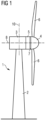
- Fig. 1 shows a wind turbine 1.
- the wind turbine 1 comprises a nacelle 3 and a tower 2.
- the nacelle 3 is mounted at the top of the tower 2.
- the nacelle 3 is mounted rotatable relative to the tower 2 around a yaw axis 10 by means of a yaw bearing.
- the wind turbine 1 also comprises a hub 4 with three rotor blades 6 (of which two rotor blades 6 are depicted in Fig. 1 ).
- the hub 4 is mounted rotatable relative to the nacelle 3 by means of a main bearing 7.
- the hub 4 is mounted rotatable about a rotor axis of rotation 8.
- the wind turbine 1 furthermore comprises a generator 5.
- the generator 5 in turn comprises an electromagnetic rotor connecting the generator 5 with the hub 4. If the hub 4 is connected directly to the generator 5, the wind turbine 1 is referred to as a gearless, direct-driven wind turbine. Such a generator 5 is referred as direct drive generator 5.
- the hub 4 may also be connected to the generator 5 via a gear box 9 (see Fig. 2 ).
- This type of wind turbine 1 is referred to as a geared wind turbine.
- the present invention is suitable for both types of wind turbines 1.
- the generator 5 is accommodated within the nacelle 3.
- the generator 5 is arranged and prepared for converting the rotational energy from the hub 4 into electrical energy in the shape of an AC power.
- the first control device can be either integrated in the wind turbine 1 or a remote control device.
- the first control device as a remote control device can be configured to control a plurality of adjacent wind turbines 1 of a wind farm.
- the remote control device is preferably connected to the wind turbines 1 of the wind farm in a wireless manner.
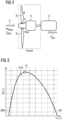
- Fig. 2 shows a schematic configuration of a wind-turbine-generator-system (WTG) according to an embodiment.
- the wind having a wind speed U drives the blades 6 and the hub 4 which is connected to the electromagnetic rotor of the generator 5 via a gearbox 9.
- the hub 4 rotates with a rotor speed ⁇ rot.
- the blades 6 are adjusted to have a (preferably common) target pitch angle ⁇ which is an orientation of the blades 6 around the longitudinal axes of the respective blades 6.
- the wind rotates the hub 4 by an aerodynamic power Pwareo and an aerodynamic torque Taero.
- the first control device determines a set point of the target torque TCtrl of the generator 5.
- a mechanical efficiency of a system consisting of the blades 6, the hub 4 and the gearbox 9 is designated by reference sign ⁇ mech.
- the first control device is configured to acquire a yaw misalignment ⁇ of the wind turbine 1, which yaw misalignment ⁇ is a difference between an actual yaw angle of the nacelle 3 and the hub 4, and a wind direction at the wind turbine 1.
- the first control device can either be configured to directly measure the wind direction or to receive information about the wind direction from a remote device (for example from a second control device for controlling a plurality of wind turbines 1 in a wind farm).
- the first control device is further configured to determine at least one of a target pitch angle ⁇ of the blade 6 and the target torque TCtrl of the generator 5 based on the yaw misalignment ⁇ to optimize a power output from the wind turbine 1.
- the first control device can be configured to determine the at least one of the target pitch angle ⁇ of the blade 6 and the target torque TCtrl of the generator 5 based on the yaw misalignment ⁇ to maximize a power output from the wind turbine 1.
- the power output of the wind turbine 1 is the output amount of electrical energy per unit time.
- the first control device is configured to determine the at least one of the target pitch angle ⁇ of the blade 6 and the target torque TCtrl of the generator 5 by calculating the target pitch angle ⁇ of the blade 6 as a function of the incoming wind speed U, the rotor speed ⁇ rot of the bub 4 and the yaw misalignment ⁇ , and by calculating the target torque TCtrl as a function of the rotor speed ⁇ orot and the yaw misalignment ⁇ .
- the first control device can be configured to determine the at least one of the target pitch angle ⁇ of the blade 6 and the target torque TCtrl of the generator 5 by considering a lookup-table, in which a relation between the incoming wind speed U, the rotor speed ⁇ rot of the hub 4 and the yaw misalignment ⁇ , and/or a relation between the target torque TCtrl and the rotor speed ⁇ rot and the yaw misalignment ⁇ are stored.
- Fig. 3 shows operational points 21, 210 according to an embodiment vis-à-vis the prior art on a graphs 20, 200, which represent an aerodynamic power coefficient cp against a tip-speed ratio (TSR) ⁇ , respectively.
- the tip-speed ratio ⁇ is a ratio between a tangential speed of the tip of a blade 6 and the actual wind speed U.
- Both graphs 20, 200 are plotted at a given yaw misalignment ⁇ .
- Reference sign 200 designates a prior art graph, on which an operational point 210 is set, which does not consider the yaw misalignment ⁇ .
- Reference sign 20 designates a graph according to an embodiment of the present invention, on which an operational point 21 is set, which considers the yaw misalignment ⁇ .
- the operational point 21 of the present invention is an optimum operational point, while the operational point 210 of the prior art is a sub-optimum operational point 21.
- the first control device is configured to determine the at least one of the target pitch angle ⁇ of the blade 6 and the target torque TCtrl of the generator 5 such that a tip-speed ratio ⁇ is set, at which a power coefficient cp of the wind turbine 1 becomes an optimum at the given yaw misalignment ⁇ .
- the control algorithm would not take the yaw misalignment ⁇ into account, the wind turbine 1 would converge to the sub-optimum operational point 210. However, by taking the yaw misalignment ⁇ into account, the loss of efficiency is removed, and the wind turbine performance is optimized.
- the graphs 200, 210 of the aerodynamic power coefficient cp against the tip-speed ratio ⁇ are the same for the prior art and the present invention; however, the graphs 200, 210 of the aerodynamic power coefficient cp against the tip-speed ratio ⁇ of prior art and the present invention can be different from each other.
- the present invention is particularly useful in controlling the wind farm, where a plurality of adjacent wind turbines 1 is provided.
- a wind turbine 1 produces a wake effect to an adjacent, downstream wind turbine 1, which wake effect could impair the output power of the adjacent, downstream wind turbine 1 and thus the efficiency of the entire wind farm.
- a second control device (not shown) is provided which minimizes the loss of efficiency by minimizing the wake effect.
- This is achieved by setting a yaw misalignment ⁇ of a specific wind turbine 1 so as to deflect the wake away from other wind turbines 1.
- the term yaw misalignment ⁇ here relates to a desired difference between the wind direction at the wind turbine 1 and the adjusted actual (and desired) yaw angle.
- the specific wind turbine 1 will have a reduced output power, but on the other hand, the wake effects to other wind turbines 1 are minimized, which in turn improves the overall efficiency of the entire wind farm.
- the second control device is thus configured to determine the respective actual yaw angles of the plurality of adjacent wind turbines 1 based on wake conditions between the plurality of adjacent wind turbines 1.
- a total power output of the wind farm becomes an optimum. For example, the total power output of the wind farm is maximized.
- the first and second control devices can be either integrated as a unit or separate control devices.
Landscapes
- Engineering & Computer Science (AREA)
- Life Sciences & Earth Sciences (AREA)
- Sustainable Development (AREA)
- Sustainable Energy (AREA)
- Chemical & Material Sciences (AREA)
- Combustion & Propulsion (AREA)
- Mechanical Engineering (AREA)
- General Engineering & Computer Science (AREA)
- Physics & Mathematics (AREA)
- Fluid Mechanics (AREA)
- Wind Motors (AREA)
Claims (12)
- System, das eine Windkraftanlage (1) und eine erste Steuervorrichtung umfasst, wobei
die Windkraftanlage (1) Folgendes umfasst:einen Turm (2);eine Gondel (3), die derart relativ zu dem Turm (2) um eine Gierachse (10) drehbar angebracht ist, dass die Gondel (3) in einem Ist-Gierwinkel ausgerichtet wird;eine Nabe (4), die relativ zu der Gondel (3) um eine Drehachse (8) drehbar angebracht ist;mindestens ein an der Nabe (4) angebrachtes Blatt (6); undeinen Generator (5), der in der Gondel (3) angeordnet ist und einen mit der Nabe (4) verbundenen elektromagnetischen Rotor umfasst, wobei der Generator (5) dazu ausgelegt ist, eine Drehenergie von dem elektromagnetischen Rotor in eine elektrische Energie umzuwandeln; unddie erste Steuervorrichtung zu Folgendem ausgelegt ist:Erfassen einer Gierfehlausrichtung (γ) der Windkraftanlage (1), wobei die Gierfehlausrichtung (γ) eine Differenz zwischen dem Ist-Gierwinkel und einer Windrichtung an der Windkraftanlage (1) ist; undBestimmen eines Zielanstellwinkels (β) des Blatts (6) durch Berechnen des Zielanstellwinkels (β) des Blatts (6) in Abhängigkeit von einer ankommenden Windgeschwindigkeit (U), einer Rotordrehzahl (ωrot) der Nabe (4) und der Gierfehlausrichtung (γ), um eine Leistungsabgabe von der Windkraftanlage (1) zu optimieren, oder eines Zieldrehmoments (TCtrl) des Generators (5) durch Berechnen des Zieldrehmoments (TCtrl) in Abhängigkeit von der Rotordrehzahl (ωrot) und der Gierfehlausrichtung (γ), um eine Leistungsabgabe von der Windkraftanlage (1) zu optimieren. - System nach dem vorhergehenden Anspruch, wobei die erste Steuervorrichtung dazu ausgelegt ist, das mindestens eine des Zielanstellwinkels (β) des Blatts (6) und des Zieldrehmoments (TCtrl) des Generators (5) unter Berücksichtigung einer Nachschlagetabelle zu bestimmen, wobei eine Relation zwischen der ankommenden Windgeschwindigkeit (U), der Rotordrehzahl (ωrot) der Nabe (4) und der Gierfehlausrichtung (γ) und/oder eine Relation zwischen dem Zieldrehmoment (TCtrl) und der Rotordrehzahl (ωrot) und der Gierfehlausrichtung (γ) gespeichert sind.
- System nach einem der vorhergehenden Ansprüche, wobei die erste Steuervorrichtung entweder in die Windkraftanlage (1) integriert oder eine Fernsteuervorrichtung ist.
- System nach einem der vorhergehenden Ansprüche, wobei die erste Steuervorrichtung dazu ausgelegt ist, das mindestens eine des Zielanstellwinkels (β) des Blatts (6) und des Zieldrehmoments (TCtrl) des Generators (5) derart zu bestimmen, dass eine Schnelllaufzahl (λ) eingestellt wird, bei der ein Leistungskoeffizient (cp) der Windkraftanlage (1) bei der gegebenen Gierfehlausrichtung (γ) optimiert wird.
- Windpark, der das System nach einem der vorhergehenden Ansprüche umfasst, wobei eine Mehrzahl von benachbarten Windkraftanlagen (1) bereitgestellt ist und der Windpark eine zweite Steuervorrichtung umfasst, die dazu ausgelegt ist, die jeweiligen Ist-Gierwinkel der Mehrzahl von benachbarten Windkraftanlagen (1) basierend auf Nachlaufbedingungen zwischen der Mehrzahl von benachbarten Windkraftanlagen (1) zu bestimmen.
- Windpark nach dem vorhergehenden Anspruch, wobei die zweite Steuervorrichtung, die dazu ausgelegt ist, die jeweiligen Ist-Gierwinkel der Mehrzahl von benachbarten Windkraftanlagen (1) basierend auf den Nachlaufbedingungen zwischen der Mehrzahl von benachbarten Windkraftanlagen (1) derart zu bestimmen, dass eine Gesamtleistungsabgabe des Windparks optimiert wird.
- Windpark nach einem der Ansprüche 5 und 6, wobei die erste und die zweite Steuervorrichtung entweder als eine Einheit integriert oder separate Steuervorrichtungen sind.
- Verfahren zum Steuern einer Windkraftanlage (1), wobei die Windkraftanlage (1) einen Turm (2); eine Gondel (3), die derart relativ zu dem Turm (2) um eine Gierachse (10) drehbar angebracht ist, dass die Gondel (3) in einem Ist-Gierwinkel ausgerichtet wird; eine Nabe (4), die relativ zu der Gondel (3) um eine Drehachse (8) drehbar angebracht ist; mindestens ein an der Nabe (4) angebrachtes Blatt (6); und einen Generator (5) umfasst, der in der Gondel (3) angeordnet ist und einen mit der Nabe (4) verbundenen elektromagnetischen Rotor umfasst, wobei der Generator (5) dazu ausgelegt ist, eine Drehenergie von dem elektromagnetischen Rotor in eine elektrische Energie umzuwandeln; und
wobei das Verfahren die folgenden Schritte umfasst:Erfassen einer Gierfehlausrichtung (γ) der Windkraftanlage (1), wobei die Gierfehlausrichtung (γ) eine Differenz zwischen dem Ist-Gierwinkel und einer Windrichtung an der Windkraftanlage (1) ist; undBestimmen eines Zielanstellwinkels (β) des Blatts (6) durch Berechnen des Zielanstellwinkels (β) des Blatts (6) in Abhängigkeit von einer ankommenden Windgeschwindigkeit (U), einer Rotordrehzahl (ωrot) der Nabe (4) und der Gierfehlausrichtung (γ), um eine Leistungsabgabe von der Windkraftanlage (1) zu optimieren, oder eines Zieldrehmoments (TCtrl) des Generators (5) durch Berechnen des Zieldrehmoments (TCtrl) in Abhängigkeit von der Rotordrehzahl (ωrot) und der Gierfehlausrichtung (γ), um eine Leistungsabgabe von der Windkraftanlage (1) zu optimieren. - Verfahren nach dem vorhergehenden Anspruch, wobei das mindestens eine des Zielanstellwinkels (β) des Blatts (6) und des Zieldrehmoments (TCtrl) des Generators (5) unter Berücksichtigung einer Nachschlagetabelle bestimmt wird, wobei eine Relation zwischen der ankommenden Windgeschwindigkeit (U), der Rotordrehzahl (ωrot) der Nabe (4) und der Gierfehlausrichtung (γ) und eine Relation zwischen dem Zieldrehmoment (TCtrl) und der Rotordrehzahl (ωrot) und der Gierfehlausrichtung (γ) gespeichert sind.
- Verfahren nach einem der Ansprüche 8 bis 9, wobei das mindestens eine des Zielanstellwinkels (β) des Blatts (6) und des Zieldrehmoments (TCtrl) des Generators (5) derart bestimmt wird, dass eine Schnelllaufzahl (λ) eingestellt wird, bei der ein Leistungskoeffizient (cp) der Windkraftanlage (1) bei der gegebenen Gierfehlausrichtung (γ) optimiert wird.
- Verfahren nach einem der Ansprüche 8 bis 10, wobei eine Mehrzahl von benachbarten Windkraftanlagen (1) bereitgestellt sind und die jeweiligen Ist-Gierwinkel der Mehrzahl von benachbarten Windkraftanlagen (1) basierend auf Nachlaufbedingungen zwischen der Mehrzahl von benachbarten Windkraftanlagen (1) bestimmt werden.
- Verfahren nach einem der Ansprüche 8 bis 11, wobei die jeweiligen Ist-Gierwinkel der Mehrzahl von benachbarten Windkraftanlagen (1) basierend auf den Nachlaufbedingungen zwischen der Mehrzahl von benachbarten Windkraftanlagen (1) derart gesteuert werden, dass eine Gesamtleistungsabgabe des Windparks optimiert wird.
Applications Claiming Priority (2)
| Application Number | Priority Date | Filing Date | Title |
|---|---|---|---|
| EP21382095.4A EP4039967A1 (de) | 2021-02-05 | 2021-02-05 | Verfahren und system zur optimierung der leistung einer windturbine mit gierfehlausrichtung |
| PCT/EP2022/050522 WO2022167180A1 (en) | 2021-02-05 | 2022-01-12 | Method and system for optimizing power output of a wind turbine with yaw misalignment |
Publications (3)
| Publication Number | Publication Date |
|---|---|
| EP4248088A1 EP4248088A1 (de) | 2023-09-27 |
| EP4248088B1 true EP4248088B1 (de) | 2024-11-13 |
| EP4248088C0 EP4248088C0 (de) | 2024-11-13 |
Family
ID=74732827
Family Applications (2)
| Application Number | Title | Priority Date | Filing Date |
|---|---|---|---|
| EP21382095.4A Pending EP4039967A1 (de) | 2021-02-05 | 2021-02-05 | Verfahren und system zur optimierung der leistung einer windturbine mit gierfehlausrichtung |
| EP22700333.2A Active EP4248088B1 (de) | 2021-02-05 | 2022-01-12 | Verfahren und system zur optimierung der leistung einer windturbine mit gierfehlausrichtung |
Family Applications Before (1)
| Application Number | Title | Priority Date | Filing Date |
|---|---|---|---|
| EP21382095.4A Pending EP4039967A1 (de) | 2021-02-05 | 2021-02-05 | Verfahren und system zur optimierung der leistung einer windturbine mit gierfehlausrichtung |
Country Status (5)
| Country | Link |
|---|---|
| US (1) | US12352241B2 (de) |
| EP (2) | EP4039967A1 (de) |
| CN (1) | CN116867964A (de) |
| ES (1) | ES3010542T3 (de) |
| WO (1) | WO2022167180A1 (de) |
Families Citing this family (1)
| Publication number | Priority date | Publication date | Assignee | Title |
|---|---|---|---|---|
| CN120777144B (zh) * | 2025-06-25 | 2026-02-06 | 华北电力大学 | 风电场多目标偏航尾流优化方法、电子设备及存储介质 |
Family Cites Families (19)
| Publication number | Priority date | Publication date | Assignee | Title |
|---|---|---|---|---|
| US5155375A (en) * | 1991-09-19 | 1992-10-13 | U.S. Windpower, Inc. | Speed control system for a variable speed wind turbine |
| EP1597476A1 (de) * | 2003-02-18 | 2005-11-23 | Forskningscenter Riso | Verfahren zur steuerung der aerodynamischen last einer windturbine auf grundlage von lokaler schaufelströmungsmessung |
| US8183707B2 (en) * | 2007-10-30 | 2012-05-22 | General Electric Company | Method of controlling a wind energy system and wind speed sensor free wind energy system |
| WO2010086688A1 (en) * | 2009-01-28 | 2010-08-05 | Clipper Windpower, Inc. | Load peak mitigation method and control system for a wind turbine |
| UA99876C2 (ru) * | 2011-05-19 | 2012-10-10 | Мита-Текник А/С | Способ управления ориентацией ветрового генератора и ветровой генератор |
| US8317471B2 (en) * | 2011-11-29 | 2012-11-27 | General Electric Company | Method for preventing rotor overspeed of a wind turbine |
| US8890349B1 (en) * | 2012-01-19 | 2014-11-18 | Northern Power Systems, Inc. | Load reduction system and method for a wind power unit |
| US9303626B2 (en) * | 2012-12-18 | 2016-04-05 | General Electric Company | Control system and method for mitigating loads during yaw error on a wind turbine |
| EP2754887B1 (de) * | 2013-01-14 | 2016-01-06 | ALSTOM Renewable Technologies | Verfahren zum Betreiben eines Windturbinenrotationssystems sowie Windturbinenrotationssystem |
| EP2754886B1 (de) * | 2013-01-14 | 2016-01-06 | ALSTOM Renewable Technologies | Verfahren zum Betreiben eines Windturbinenrotationssystems sowie Windturbinenrotationssystem |
| US9388792B2 (en) * | 2013-03-15 | 2016-07-12 | Frontier Wind, Llc | Distributed control system |
| WO2015048972A1 (en) * | 2013-10-01 | 2015-04-09 | Vestas Wind Systems A/S | Safe mode operation at high yaw error |
| ES2538739B1 (es) * | 2013-12-23 | 2016-04-14 | Acciona Windpower, S.A. | Método de control de aerogenerador |
| DK201670197A1 (en) * | 2016-04-04 | 2017-10-23 | Mita-Teknik As | A system and a method for optimal yaw control |
| US10465655B2 (en) * | 2016-07-05 | 2019-11-05 | Inventus Holdings, Llc | Wind turbine wake steering apparatus |
| DK179188B1 (en) * | 2016-07-06 | 2018-01-22 | Envision Energy (Jiangsu) Co Ltd | Wind turbine and a method of operating a wind turbine |
| EP3343025A1 (de) * | 2016-12-30 | 2018-07-04 | Acciona Windpower, S.A. | Verfahren zur reduzierung von lasten, die auf ein windturbinengierungssystem wirken |
| US11136961B2 (en) * | 2017-06-01 | 2021-10-05 | General Electric Company | System and method for optimizing power output of a wind turbine during an operational constraint |
| CN110985309B (zh) * | 2019-12-09 | 2022-03-11 | 远景智能国际私人投资有限公司 | 偏航对风异常检测方法、装置、设备和存储介质 |
-
2021
- 2021-02-05 EP EP21382095.4A patent/EP4039967A1/de active Pending
-
2022
- 2022-01-12 ES ES22700333T patent/ES3010542T3/es active Active
- 2022-01-12 EP EP22700333.2A patent/EP4248088B1/de active Active
- 2022-01-12 US US18/274,913 patent/US12352241B2/en active Active
- 2022-01-12 CN CN202280013585.3A patent/CN116867964A/zh active Pending
- 2022-01-12 WO PCT/EP2022/050522 patent/WO2022167180A1/en not_active Ceased
Also Published As
| Publication number | Publication date |
|---|---|
| US20240093669A1 (en) | 2024-03-21 |
| EP4248088A1 (de) | 2023-09-27 |
| WO2022167180A1 (en) | 2022-08-11 |
| US12352241B2 (en) | 2025-07-08 |
| ES3010542T3 (en) | 2025-04-03 |
| EP4248088C0 (de) | 2024-11-13 |
| CN116867964A (zh) | 2023-10-10 |
| EP4039967A1 (de) | 2022-08-10 |
Similar Documents
| Publication | Publication Date | Title |
|---|---|---|
| EP2096300B1 (de) | Verfahren zur Steuerung der Schnellaufzahl von Windturbinenschaufeln | |
| EP2067988B1 (de) | Verfahren und Vorrichtung zur Reduktion der asymmetrischen Rotorlasten beim Abstellen einer Windturbine | |
| EP2657518B1 (de) | Verfahren und Systeme zum Betrieb einer Windkraftanlage in geräuscharmer Betriebsart | |
| EP2169219B1 (de) | System und Verfahren zur Steuerung einer Windturbine bei elektrischen Energieversorgungsnetzverlust und verändernden Windverhältnissen | |
| EP2273105B1 (de) | Verfahren und Vorrichtung zur geräuschoptimierten Steuerung einer Windkraftanlage | |
| DK2096301T3 (en) | Method of operating a wind turbine plant under high wind conditions | |
| US8212373B2 (en) | Wind plant and method for increasing energy capture in a wind plant | |
| US20060002794A1 (en) | Methods and apparatus for twist bend coupled (TCB) wind turbine blades | |
| EP2522853B1 (de) | Drehmoment-Drehzahlsteuerung einer Windturbine | |
| EP1772623A1 (de) | Aktive Strömungsregelung eines Rotorblattes einer Windkraftanlage | |
| WO2004099608A1 (en) | Wind turbine blade with lift-regulating means | |
| EP2481916A1 (de) | Windradstromerzeugungssystem mit Hydraulikgetriebe | |
| EP3964706B1 (de) | Verfahren zum betrieb einer windturbine sowie windturbine | |
| KR102042259B1 (ko) | 풍력발전시스템 및 그것의 구동 정지 방법 | |
| US20220341391A1 (en) | Yaw systems and methods | |
| EP4248088B1 (de) | Verfahren und system zur optimierung der leistung einer windturbine mit gierfehlausrichtung | |
| CN114423941B (zh) | 控制风力涡轮机的控制装置和方法 | |
| EP4280412A1 (de) | System und verfahren zur steuerung einer vielzahl von stromgeneratoren | |
| US12331716B2 (en) | Hub assembly for a wind turbine having a spacer |
Legal Events
| Date | Code | Title | Description |
|---|---|---|---|
| STAA | Information on the status of an ep patent application or granted ep patent |
Free format text: STATUS: UNKNOWN |
|
| STAA | Information on the status of an ep patent application or granted ep patent |
Free format text: STATUS: THE INTERNATIONAL PUBLICATION HAS BEEN MADE |
|
| PUAI | Public reference made under article 153(3) epc to a published international application that has entered the european phase |
Free format text: ORIGINAL CODE: 0009012 |
|
| STAA | Information on the status of an ep patent application or granted ep patent |
Free format text: STATUS: REQUEST FOR EXAMINATION WAS MADE |
|
| 17P | Request for examination filed |
Effective date: 20230619 |
|
| AK | Designated contracting states |
Kind code of ref document: A1 Designated state(s): AL AT BE BG CH CY CZ DE DK EE ES FI FR GB GR HR HU IE IS IT LI LT LU LV MC MK MT NL NO PL PT RO RS SE SI SK SM TR |
|
| DAV | Request for validation of the european patent (deleted) | ||
| DAX | Request for extension of the european patent (deleted) | ||
| GRAP | Despatch of communication of intention to grant a patent |
Free format text: ORIGINAL CODE: EPIDOSNIGR1 |
|
| STAA | Information on the status of an ep patent application or granted ep patent |
Free format text: STATUS: GRANT OF PATENT IS INTENDED |
|
| INTG | Intention to grant announced |
Effective date: 20240607 |
|
| GRAS | Grant fee paid |
Free format text: ORIGINAL CODE: EPIDOSNIGR3 |
|
| GRAA | (expected) grant |
Free format text: ORIGINAL CODE: 0009210 |
|
| STAA | Information on the status of an ep patent application or granted ep patent |
Free format text: STATUS: THE PATENT HAS BEEN GRANTED |
|
| AK | Designated contracting states |
Kind code of ref document: B1 Designated state(s): AL AT BE BG CH CY CZ DE DK EE ES FI FR GB GR HR HU IE IS IT LI LT LU LV MC MK MT NL NO PL PT RO RS SE SI SK SM TR |
|
| REG | Reference to a national code |
Ref country code: GB Ref legal event code: FG4D |
|
| REG | Reference to a national code |
Ref country code: CH Ref legal event code: EP |
|
| REG | Reference to a national code |
Ref country code: DE Ref legal event code: R096 Ref document number: 602022007704 Country of ref document: DE |
|
| REG | Reference to a national code |
Ref country code: IE Ref legal event code: FG4D |
|
| U01 | Request for unitary effect filed |
Effective date: 20241203 |
|
| U07 | Unitary effect registered |
Designated state(s): AT BE BG DE DK EE FI FR IT LT LU LV MT NL PT RO SE SI Effective date: 20241212 |
|
| PG25 | Lapsed in a contracting state [announced via postgrant information from national office to epo] |
Ref country code: HR Free format text: LAPSE BECAUSE OF FAILURE TO SUBMIT A TRANSLATION OF THE DESCRIPTION OR TO PAY THE FEE WITHIN THE PRESCRIBED TIME-LIMIT Effective date: 20241113 Ref country code: IS Free format text: LAPSE BECAUSE OF FAILURE TO SUBMIT A TRANSLATION OF THE DESCRIPTION OR TO PAY THE FEE WITHIN THE PRESCRIBED TIME-LIMIT Effective date: 20250313 |
|
| U20 | Renewal fee for the european patent with unitary effect paid |
Year of fee payment: 4 Effective date: 20250312 |
|
| PG25 | Lapsed in a contracting state [announced via postgrant information from national office to epo] |
Ref country code: GR Free format text: LAPSE BECAUSE OF FAILURE TO SUBMIT A TRANSLATION OF THE DESCRIPTION OR TO PAY THE FEE WITHIN THE PRESCRIBED TIME-LIMIT Effective date: 20250214 |
|
| PG25 | Lapsed in a contracting state [announced via postgrant information from national office to epo] |
Ref country code: PL Free format text: LAPSE BECAUSE OF FAILURE TO SUBMIT A TRANSLATION OF THE DESCRIPTION OR TO PAY THE FEE WITHIN THE PRESCRIBED TIME-LIMIT Effective date: 20241113 |
|
| PG25 | Lapsed in a contracting state [announced via postgrant information from national office to epo] |
Ref country code: RS Free format text: LAPSE BECAUSE OF FAILURE TO SUBMIT A TRANSLATION OF THE DESCRIPTION OR TO PAY THE FEE WITHIN THE PRESCRIBED TIME-LIMIT Effective date: 20250213 |
|
| PG25 | Lapsed in a contracting state [announced via postgrant information from national office to epo] |
Ref country code: SM Free format text: LAPSE BECAUSE OF FAILURE TO SUBMIT A TRANSLATION OF THE DESCRIPTION OR TO PAY THE FEE WITHIN THE PRESCRIBED TIME-LIMIT Effective date: 20241113 |
|
| PG25 | Lapsed in a contracting state [announced via postgrant information from national office to epo] |
Ref country code: SK Free format text: LAPSE BECAUSE OF FAILURE TO SUBMIT A TRANSLATION OF THE DESCRIPTION OR TO PAY THE FEE WITHIN THE PRESCRIBED TIME-LIMIT Effective date: 20241113 |
|
| PG25 | Lapsed in a contracting state [announced via postgrant information from national office to epo] |
Ref country code: CZ Free format text: LAPSE BECAUSE OF FAILURE TO SUBMIT A TRANSLATION OF THE DESCRIPTION OR TO PAY THE FEE WITHIN THE PRESCRIBED TIME-LIMIT Effective date: 20241113 |
|
| REG | Reference to a national code |
Ref country code: CH Ref legal event code: PL |
|
| PG25 | Lapsed in a contracting state [announced via postgrant information from national office to epo] |
Ref country code: MC Free format text: LAPSE BECAUSE OF FAILURE TO SUBMIT A TRANSLATION OF THE DESCRIPTION OR TO PAY THE FEE WITHIN THE PRESCRIBED TIME-LIMIT Effective date: 20241113 |
|
| PLBE | No opposition filed within time limit |
Free format text: ORIGINAL CODE: 0009261 |
|
| STAA | Information on the status of an ep patent application or granted ep patent |
Free format text: STATUS: NO OPPOSITION FILED WITHIN TIME LIMIT |
|
| PG25 | Lapsed in a contracting state [announced via postgrant information from national office to epo] |
Ref country code: CH Free format text: LAPSE BECAUSE OF NON-PAYMENT OF DUE FEES Effective date: 20250131 |
|
| 26N | No opposition filed |
Effective date: 20250814 |
|
| PG25 | Lapsed in a contracting state [announced via postgrant information from national office to epo] |
Ref country code: IE Free format text: LAPSE BECAUSE OF NON-PAYMENT OF DUE FEES Effective date: 20250112 |
|
| U20 | Renewal fee for the european patent with unitary effect paid |
Year of fee payment: 5 Effective date: 20260202 |
|
| PGFP | Annual fee paid to national office [announced via postgrant information from national office to epo] |
Ref country code: GB Payment date: 20260126 Year of fee payment: 5 |
|
| PGFP | Annual fee paid to national office [announced via postgrant information from national office to epo] |
Ref country code: ES Payment date: 20260210 Year of fee payment: 5 |
|
| PGFP | Annual fee paid to national office [announced via postgrant information from national office to epo] |
Ref country code: NO Payment date: 20260120 Year of fee payment: 5 |