EP4246799A1 - Dc motor driving system and method - Google Patents
Dc motor driving system and method Download PDFInfo
- Publication number
- EP4246799A1 EP4246799A1 EP22200278.4A EP22200278A EP4246799A1 EP 4246799 A1 EP4246799 A1 EP 4246799A1 EP 22200278 A EP22200278 A EP 22200278A EP 4246799 A1 EP4246799 A1 EP 4246799A1
- Authority
- EP
- European Patent Office
- Prior art keywords
- motor
- supply device
- power supply
- microprocessor
- driving system
- Prior art date
- Legal status (The legal status is an assumption and is not a legal conclusion. Google has not performed a legal analysis and makes no representation as to the accuracy of the status listed.)
- Pending
Links
Images



Classifications
-
- H—ELECTRICITY
- H02—GENERATION; CONVERSION OR DISTRIBUTION OF ELECTRIC POWER
- H02P—CONTROL OR REGULATION OF ELECTRIC MOTORS, ELECTRIC GENERATORS OR DYNAMO-ELECTRIC CONVERTERS; CONTROLLING TRANSFORMERS, REACTORS OR CHOKE COILS
- H02P23/00—Arrangements or methods for the control of AC motors characterised by a control method other than vector control
- H02P23/14—Estimation or adaptation of motor parameters, e.g. rotor time constant, flux, speed, current or voltage
-
- H—ELECTRICITY
- H02—GENERATION; CONVERSION OR DISTRIBUTION OF ELECTRIC POWER
- H02P—CONTROL OR REGULATION OF ELECTRIC MOTORS, ELECTRIC GENERATORS OR DYNAMO-ELECTRIC CONVERTERS; CONTROLLING TRANSFORMERS, REACTORS OR CHOKE COILS
- H02P7/00—Arrangements for regulating or controlling the speed or torque of electric DC motors
- H02P7/06—Arrangements for regulating or controlling the speed or torque of electric DC motors for regulating or controlling an individual DC dynamo-electric motor by varying field or armature current
- H02P7/18—Arrangements for regulating or controlling the speed or torque of electric DC motors for regulating or controlling an individual DC dynamo-electric motor by varying field or armature current by master control with auxiliary power
- H02P7/24—Arrangements for regulating or controlling the speed or torque of electric DC motors for regulating or controlling an individual DC dynamo-electric motor by varying field or armature current by master control with auxiliary power using discharge tubes or semiconductor devices
- H02P7/28—Arrangements for regulating or controlling the speed or torque of electric DC motors for regulating or controlling an individual DC dynamo-electric motor by varying field or armature current by master control with auxiliary power using discharge tubes or semiconductor devices using semiconductor devices
-
- H—ELECTRICITY
- H02—GENERATION; CONVERSION OR DISTRIBUTION OF ELECTRIC POWER
- H02P—CONTROL OR REGULATION OF ELECTRIC MOTORS, ELECTRIC GENERATORS OR DYNAMO-ELECTRIC CONVERTERS; CONTROLLING TRANSFORMERS, REACTORS OR CHOKE COILS
- H02P29/00—Arrangements for regulating or controlling electric motors, appropriate for both AC and DC motors
- H02P29/02—Providing protection against overload without automatic interruption of supply
- H02P29/032—Preventing damage to the motor, e.g. setting individual current limits for different drive conditions
Definitions
- the present disclosure relates to a motor driving system and method, and more particularly to a DC motor driving system and method.
- the DC motor is usually driven by a constant voltage. Under this driving condition, there is a specific relation curve between the rotational speed and the torque of the motor, as shown in FIG. 1 . Accordingly, the required torque can be obtained by adjusting the rotational speed. However, if the motor operates with the maximum torque, the torque of the motor cannot be further increased.
- the present disclosure provides a DC motor driving system and method. Based on the variable-voltage characteristic of the power supply device, the DC motor driving system and method varies the relation curve between the rotational speed and the torque of the DC motor through adjusting the motor voltage, thereby increasing the maximum torque of the DC motor. Consequently, the applicability of the DC motor is enhanced.
- a DC motor driving system includes a DC motor, a power supply device, a switch circuit, and a microprocessor.
- the power supply device is configured to provide an input electrical energy.
- the switch circuit is electrically connected between the power supply device and the DC motor for receiving the input electrical energy and outputting a motor electrical energy to the DC motor.
- the motor electrical energy includes a motor power and a motor voltage.
- the microprocessor is electrically connected to the switch circuit for controlling operation of switches in the switch circuit, and the microprocessor and the power supply device are in communication with each other.
- the DC motor driving system switchably works in a constant-voltage mode, a first variable-voltage mode, or a second variable-voltage mode.
- the input electrical energy provided by the power supply device remains unchanged.
- the microprocessor transmits a first adjusting signal to the power supply device, and the power supply device adjusts the input electrical energy according to the first adjusting signal for increasing the motor voltage and the motor power.
- the microprocessor transmits a second adjusting signal to the power supply device, and the power supply device adjusts the input electrical energy according to the second adjusting signal for decreasing the motor voltage and keeping the motor power unchanged.
- a DC motor driving method includes steps (a), (b), (c), and (d).
- a DC motor, a power supply device, a switch circuit, and a microprocessor are provided.
- the power supply device is configured to provide an input electrical energy.
- the switch circuit is electrically connected between the power supply device and the DC motor to receive the input electrical energy and output a motor electrical energy to the DC motor.
- the motor electrical energy includes a motor power and a motor voltage.
- the microprocessor is electrically connected to the switch circuit for controlling operation of switches in the switch circuit, and the microprocessor and the power supply device are in communication with each other.
- step (b) a constant-voltage mode is performed, and the input electrical energy provided by the power supply device is controlled to remain unchanged.
- step (c) a first variable-voltage mode is performed, the microprocessor is controlled to transmit a first adjusting signal to the power supply device, and the power supply device is controlled to adjust the input electrical energy according to the first adjusting signal for increasing the motor voltage and the motor power.
- step (d) a second variable-voltage mode is performed, the microprocessor is controlled to transmit a second adjusting signal to the power supply device, and the power supply device is controlled to adjust the input electrical energy according to the second adjusting signal for decreasing the motor voltage and keeping the motor power unchanged.
- a DC motor driving system is provided.
- the DC motor driving system is electrically connected to a power supply device configured to provide an input electrical energy.
- the DC motor driving system includes a DC motor, a power supply device, a switch circuit, and a microprocessor.
- the switch circuit is electrically connected between the power supply device and the DC motor for receiving the input electrical energy and outputting a motor electrical energy to the DC motor.
- the motor electrical energy includes a motor power and a motor voltage.
- the microprocessor is electrically connected to the switch circuit for controlling operation of switches in the switch circuit, and the microprocessor and the power supply device are in communication with each other.
- the DC motor driving system switchably works in a constant-voltage mode, a first variable-voltage mode, or a second variable-voltage mode.
- the input electrical energy provided by the power supply device remains unchanged.
- the microprocessor transmits a first adjusting signal to the power supply device, and the power supply device adjusts the input electrical energy according to the first adjusting signal for increasing the motor voltage and the motor power.
- the microprocessor transmits a second adjusting signal to the power supply device, and the power supply device adjusts the input electrical energy according to the second adjusting signal for decreasing the motor voltage and keeping the motor power unchanged.
- FIG. 2 is a schematic block diagram illustrating a DC motor driving system according to an embodiment of the present disclosure.
- the electrical energy transmission path is depicted by solid lines, and the signal transmission path is depicted by dashed lines.
- the DC motor driving system 1 includes a DC motor 11, a power supply device 12, a switch circuit 13, and a microprocessor 14.
- the power supply device 12 is configured to provide an input electrical energy.
- the power supply device 12 may adopt a USB PD (universal serial bus power delivery) standard, but not limited thereto.
- USB PD universal serial bus power delivery
- the switch circuit 13 is electrically connected between the power supply device 12 and the DC motor 11 to receive the input electrical energy from the power supply device 12 and output a motor electrical energy to the DC motor 11, and the motor electrical energy includes a motor power and a motor voltage.
- the microprocessor 14 is electrically connected to the switch circuit 13 for controlling the operation of the switches in the switch circuit 13. Further, the microprocessor 14 and the power supply device 12 are in communication with each other, namely there is a two-way communication between the microprocessor 14 and the power supply device 12.
- the DC motor driving system 1 switchably works in a constant-voltage mode, a first variable-voltage mode, or a second variable-voltage mode.
- the DC motor driving system 1 works in the constant-voltage mode, the input electrical energy provided by the power supply device 12 remains unchanged, and the motor electrical energy received by the DC motor 11 remains unchanged correspondingly.
- the relation between the rotational speed and the torque of the DC motor 11 is similar to that shown in FIG. 1 .
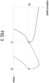
- FIG. 3 schematically shows a relation curve between the rotational speed and the torque of the DC motor 11 under the first variable-voltage mode.
- the relation curve before the power supply device 12 adjusting the input electrical energy is represented by a solid line
- the relation curve after the power supply device 12 adjusting the input electrical energy is represented by a dashed line.
- T1 represents the maximum torque of the DC motor 11 before the motor voltage increases
- T2 represents the maximum torque of the DC motor 11 after the motor voltage increases
- R1 represents the rotational speed of the DC motor 11 corresponding to the maximum torques T1 and T2.
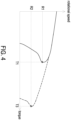
- FIG. 4 schematically shows a relation curve between the rotational speed and the torque of the DC motor 11 in the second variable-voltage mode.
- the relation curve before the power supply device 12 adjusting the input electrical energy is represented by a solid line
- the relation curve after the power supply device 12 adjusting the input electrical energy is represented by a dashed line.
- T1 represents the maximum torque of the DC motor 11 before the motor voltage decreases
- T3 represents the maximum torque of the DC motor 11 after the motor voltage decreases
- R1 represents the rotational speed of the DC motor 11 corresponding to the maximum torque T1
- R2 represents the rotational speed of the DC motor 11 corresponding to the maximum torque T2.
- the DC motor 11 reaches the maximum torque at a lower rotational speed.
- the maximum torque of the DC motor 11 can be increased by changing the relation curve between the rotational speed and the torque of the DC motor 11 through adjusting the motor voltage. Consequently, the applicability of the DC motor 11 is enhanced.
- the DC motor driving system 1 further includes an external control button 151, and the user may switch the DC motor driving system 1 to work in the constant-voltage mode, the first variable-voltage mode, or the second variable voltage mode through operating the external control button 151.
- the microprocessor 14 also can switch the work mode of the DC motor driving system 1 according to the work state of the DC motor 11. For example, the microprocessor 14 obtains the duty cycle of the DC motor 11 and compares the duty cycle of the DC motor 11 with a preset duty cycle. If the microprocessor 14 determines that the duty cycle of the DC motor 11 is less than the preset duty cycle, the DC motor driving system 1 works in the constant-voltage mode. If the microprocessor 14 determines that the duty cycle of the DC motor 11 is greater than or equal to the preset duty cycle, which means that the DC motor 11 requires high torque to output high torque force, the DC motor driving system 1 works in the first or second variable-voltage mode.
- the microprocessor 14 compares the motor power with a rated power of the DC motor 11. If the motor power is less than the rated power, there is still room for increase in the motor power. Therefore, the microprocessor 14 transmits the first adjusting signal to the power supply device 12 so that the DC motor driving system 1 works in the first variable-voltage mode. If the motor power is equal to the rated power, the motor power can't be further increased. Therefore, the microprocessor 14 transmits the second adjusting signal to the power supply device 12 so that the DC motor driving system 1 works in the second variable-voltage mode.
- the DC motor driving system 1 further includes a current sensor 152.
- the current sensor 152 is for example but not limited to a Hall sensor.
- the current sensor 152 is configured to sense the current of the DC motor 11 and transmit a sensing signal to the microprocessor 14 correspondingly.
- the microprocessor 14 obtains the duty cycle of the DC motor 11 according to the sensing signal.
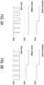
- FIG. 5A schematically shows a relation between the rotational speed, the motor voltage, and the duty cycle of the DC motor 11 driven by a constant voltage.
- FIG. 5B schematically shows a relation between the rotational speed, the motor voltage, and the duty cycle of the DC motor 11 driven by a variable voltage.
- FIG. 5A in the case that the DC motor 11 is driven by a constant voltage, when the rotational speed of the DC motor 11 decreases, the duty cycle of the DC motor 11 decreases since the motor voltage remains unchanged.
- FIG. 5A in the case that the DC motor 11 is driven by a constant voltage, when the rotational speed of the DC motor 11 decreases, the duty cycle of the DC motor 11 decreases since the motor voltage remains unchanged.
- the microprocessor 14 controls the power supply device 12 to adjust the input electrical energy through signal transmission, thereby decreasing the motor voltage and keeping the duty cycle of the DC motor 11 unchanged. It is noted that decreasing margin of the motor voltage depends on the decreasing margin of the rotational speed of the DC motor 11. Consequently, the DC motor 11 always achieves good duty cycle at different rotational speeds, thereby reducing harmonics and improving overall efficiency.
- the DC motor driving system 1 further includes a fuse 16 disposed on the electrical energy transmission path between the power supply device 12 and the switch circuit 13 to provide current protection.
- the DC motor driving system 1 further includes a voltage stabilizer 17 electrically connected between the power supply device 12 and the microprocessor 14.
- the DC motor driving system 1 further includes a driver 18, and the microprocessor 14 controls the switches in the switch circuit 13 through the driver 18.
- the DC motor driving system 1 further includes a shunt resistance 19 and an operational amplifier 20. The shunt resistance 19 is electrically connected to the current sensor 152, and the operational amplifier 20 is electrically connected between the shunt resistance 19 and the microprocessor 14.
- the power supply device 12 may be independent from the DC motor driving system 1. Under this circumstance, the DC motor driving system 1 is electrically connected to the power supply device 12. The power supply device 12 is configured to provide the input electrical energy, and the DC motor driving system 1 includes the DC motor 11, the switch circuit 13, and the microprocessor 14. Since the operation of the DC motor driving system 1 and the power supply device 12 are the same as that in the above embodiments, the detailed descriptions thereof are omitted herein.
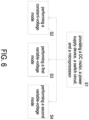
- FIG. 6 is a schematic flow chart illustrating a DC motor driving method according to an embodiment of the present disclosure.
- the DC motor driving method of the present application can be applied to the above-mentioned DC motor driving system 1.
- the DC motor driving method includes steps S1, S2, S3, and S4.
- a DC motor 11, a power supply device 12, a switch circuit 13, and a microprocessor 14 are provided.
- the power supply device 12 is configured to provide the input electrical energy.
- the switch circuit 13 is electrically connected between the power supply device 12 and the DC motor 11 to receive the input electrical energy and output the motor electrical energy to the DC motor 11, and the motor electrical energy includes the motor power and the motor voltage.
- the microprocessor 14 is electrically connected to the switch circuit 13 for controlling the operation of the switches in the switch circuit 13, and the microprocessor 14 and the power supply device 12 are in communication with each other.
- the constant-voltage mode is performed, and the input electrical energy provided by the power supply device 12 is controlled to remain unchanged.
- the first variable-voltage mode is performed, the microprocessor 14 is controlled to transmit the first adjusting signal to the power supply device 12, and the power supply device 12 is controlled to adjust the input electrical energy according to the first adjusting signal for increasing the motor voltage and the motor power.
- the second variable-voltage mode is performed, the microprocessor 14 is controlled to transmit the second adjusting signal to the power supply device 12, and the power supply device 12 is controlled to adjust the input electrical energy according to the second adjusting signal for decreasing the motor voltage and keeping the motor power unchanged.
- the steps S2, S3, and S4 are switchably performed, and the switching between the steps S2, S3, and S4 may be controlled by the user actively or may be controlled by the microprocessor 14 according to the operation state (e.g., the duty cycle) of the DC motor 11.
- the DC motor driving method further includes a step S5 of determining whether the duty cycle of the DC motor 11 is less than a preset duty cycle. If the determining result of the step S5 is satisfied, the step S2 is performed. If the determining result of the step S5 is not satisfied, the step S3 or S4 is performed.
- the DC motor driving method further includes a step S6 of determining whether the motor power is less than the rated power of the DC motor 11 when the determining result of the step S5 is not satisfied. If the determining result of the step S6 is satisfied, the step S3 is performed. If the determining result of the step S6 is not satisfied (i.e., the motor power equals the rated power), the step S4 is performed.
- the duty cycle of the DC motor 11 is obtained according to the sensing signal transmitted by the current sensor 152 sensing the current of the DC motor 11.
- the DC motor driving method further includes a step of controlling the microprocessor 14 to control the power supply device 12 to decrease the motor voltage when the rotational speed of the DC motor 11 decreases, so as to keep the duty cycle of the DC motor 11 unchanged.
- the present disclosure provides a DC motor driving system and method. Based on the variable-voltage characteristic of the power supply device, the DC motor driving system and method varies the relation curve between the rotational speed and the torque of the DC motor through adjusting the motor voltage, thereby increasing the maximum torque of the DC motor. Consequently, the applicability of the DC motor is enhanced. In addition, when the rotational speed of the DC motor decreases, the motor voltage is decreased to keep the duty cycle of the DC motor to unchanged. Consequently, the DC motor always achieves good duty cycle at different rotational speeds, thereby reducing harmonics and improving overall efficiency.
Landscapes
- Engineering & Computer Science (AREA)
- Power Engineering (AREA)
- Control Of Direct Current Motors (AREA)
Abstract
Description
- The present disclosure relates to a motor driving system and method, and more particularly to a DC motor driving system and method.
- Conventionally, the DC motor is usually driven by a constant voltage. Under this driving condition, there is a specific relation curve between the rotational speed and the torque of the motor, as shown in
FIG. 1 . Accordingly, the required torque can be obtained by adjusting the rotational speed. However, if the motor operates with the maximum torque, the torque of the motor cannot be further increased. - Therefore, there is a need of providing a DC motor driving system and method in order to overcome the drawbacks of the conventional technologies.
- The present disclosure provides a DC motor driving system and method. Based on the variable-voltage characteristic of the power supply device, the DC motor driving system and method varies the relation curve between the rotational speed and the torque of the DC motor through adjusting the motor voltage, thereby increasing the maximum torque of the DC motor. Consequently, the applicability of the DC motor is enhanced.
- In accordance with an aspect of the present disclosure, a DC motor driving system is provided. The DC motor driving system includes a DC motor, a power supply device, a switch circuit, and a microprocessor. The power supply device is configured to provide an input electrical energy. The switch circuit is electrically connected between the power supply device and the DC motor for receiving the input electrical energy and outputting a motor electrical energy to the DC motor. The motor electrical energy includes a motor power and a motor voltage. The microprocessor is electrically connected to the switch circuit for controlling operation of switches in the switch circuit, and the microprocessor and the power supply device are in communication with each other. The DC motor driving system switchably works in a constant-voltage mode, a first variable-voltage mode, or a second variable-voltage mode. When the DC motor driving system works in the constant-voltage mode, the input electrical energy provided by the power supply device remains unchanged. When the DC motor driving system works in the first variable-voltage mode, the microprocessor transmits a first adjusting signal to the power supply device, and the power supply device adjusts the input electrical energy according to the first adjusting signal for increasing the motor voltage and the motor power. When the DC motor driving system works in the second variable-voltage mode, the microprocessor transmits a second adjusting signal to the power supply device, and the power supply device adjusts the input electrical energy according to the second adjusting signal for decreasing the motor voltage and keeping the motor power unchanged.
- In accordance with another aspect of the present disclosure, a DC motor driving method is provided. The DC motor driving method includes steps (a), (b), (c), and (d). In the step (a), a DC motor, a power supply device, a switch circuit, and a microprocessor are provided. The power supply device is configured to provide an input electrical energy. The switch circuit is electrically connected between the power supply device and the DC motor to receive the input electrical energy and output a motor electrical energy to the DC motor. The motor electrical energy includes a motor power and a motor voltage. The microprocessor is electrically connected to the switch circuit for controlling operation of switches in the switch circuit, and the microprocessor and the power supply device are in communication with each other. In the step (b), a constant-voltage mode is performed, and the input electrical energy provided by the power supply device is controlled to remain unchanged. In the step (c), a first variable-voltage mode is performed, the microprocessor is controlled to transmit a first adjusting signal to the power supply device, and the power supply device is controlled to adjust the input electrical energy according to the first adjusting signal for increasing the motor voltage and the motor power. In the step (d), a second variable-voltage mode is performed, the microprocessor is controlled to transmit a second adjusting signal to the power supply device, and the power supply device is controlled to adjust the input electrical energy according to the second adjusting signal for decreasing the motor voltage and keeping the motor power unchanged.
- In accordance with further another aspect of the present disclosure, a DC motor driving system is provided. The DC motor driving system is electrically connected to a power supply device configured to provide an input electrical energy. The DC motor driving system includes a DC motor, a power supply device, a switch circuit, and a microprocessor. The switch circuit is electrically connected between the power supply device and the DC motor for receiving the input electrical energy and outputting a motor electrical energy to the DC motor. The motor electrical energy includes a motor power and a motor voltage. The microprocessor is electrically connected to the switch circuit for controlling operation of switches in the switch circuit, and the microprocessor and the power supply device are in communication with each other. The DC motor driving system switchably works in a constant-voltage mode, a first variable-voltage mode, or a second variable-voltage mode. When the DC motor driving system works in the constant-voltage mode, the input electrical energy provided by the power supply device remains unchanged. When the DC motor driving system works in the first variable-voltage mode, the microprocessor transmits a first adjusting signal to the power supply device, and the power supply device adjusts the input electrical energy according to the first adjusting signal for increasing the motor voltage and the motor power. When the DC motor driving system works in the second variable-voltage mode, the microprocessor transmits a second adjusting signal to the power supply device, and the power supply device adjusts the input electrical energy according to the second adjusting signal for decreasing the motor voltage and keeping the motor power unchanged.
-
-
FIG. 1 schematically shows a relation curve between the rotational speed and the torque of the DC motor driven by a constant voltage; -
FIG. 2 is a schematic block diagram illustrating a DC motor driving system according to an embodiment of the present disclosure; -
FIG. 3 schematically shows a relation curve between the rotational speed and the torque of the DC motor under the first variable-voltage mode; -
FIG. 4 schematically shows a relation curve between the rotational speed and the torque of the DC motor under the second variable-voltage mode; -
FIG. 5A schematically shows a relation between the rotational speed, the motor voltage, and the duty cycle of the DC motor driven by a constant voltage; -
FIG. 5B schematically shows a relation between the rotational speed, the motor voltage, and the duty cycle of the DC motor driven by a variable voltage; -
FIG. 6 is a schematic flow chart illustrating a DC motor driving method according to an embodiment of the present disclosure; and -
FIG. 7 is a schematic flow chart illustrating a variant of the DC motor driving method ofFIG. 6 . - The present disclosure will now be described more specifically with reference to the following embodiments. It is to be noted that the following descriptions of preferred embodiments of this disclosure are presented herein for purpose of illustration and description only. It is not intended to be exhaustive or to be limited to the precise form disclosed.
-
FIG. 2 is a schematic block diagram illustrating a DC motor driving system according to an embodiment of the present disclosure. InFIG. 2 , the electrical energy transmission path is depicted by solid lines, and the signal transmission path is depicted by dashed lines. As shown inFIG. 2 , the DCmotor driving system 1 includes aDC motor 11, apower supply device 12, aswitch circuit 13, and amicroprocessor 14. Thepower supply device 12 is configured to provide an input electrical energy. Thepower supply device 12 may adopt a USB PD (universal serial bus power delivery) standard, but not limited thereto. Theswitch circuit 13 is electrically connected between thepower supply device 12 and theDC motor 11 to receive the input electrical energy from thepower supply device 12 and output a motor electrical energy to theDC motor 11, and the motor electrical energy includes a motor power and a motor voltage. Themicroprocessor 14 is electrically connected to theswitch circuit 13 for controlling the operation of the switches in theswitch circuit 13. Further, themicroprocessor 14 and thepower supply device 12 are in communication with each other, namely there is a two-way communication between themicroprocessor 14 and thepower supply device 12. The DCmotor driving system 1 switchably works in a constant-voltage mode, a first variable-voltage mode, or a second variable-voltage mode. - When the DC
motor driving system 1 works in the constant-voltage mode, the input electrical energy provided by thepower supply device 12 remains unchanged, and the motor electrical energy received by theDC motor 11 remains unchanged correspondingly. In the constant-voltage mode, the relation between the rotational speed and the torque of theDC motor 11 is similar to that shown inFIG. 1 . - When the DC
motor driving system 1 works in the first variable-voltage mode, themicroprocessor 14 transmits a first adjusting signal to thepower supply device 12, and thepower supply device 12 adjusts the input electrical energy according to the first adjusting signal for increasing the motor voltage and the motor power.FIG. 3 schematically shows a relation curve between the rotational speed and the torque of theDC motor 11 under the first variable-voltage mode. InFIG. 3 , the relation curve before thepower supply device 12 adjusting the input electrical energy is represented by a solid line, and the relation curve after thepower supply device 12 adjusting the input electrical energy is represented by a dashed line. As shown inFIG. 3 , in practical applications, when the torque of theDC motor 11 reaches its maximum value, the motor voltage is increased through adjusting the input electric energy, and the motor power is increased as well. Thereby, the relation curve between the rotational speed and the torque of theDC motor 11 is varied, and theDC motor 11 can achieve greater torque at the same rotational speed. InFIG. 3 , T1 represents the maximum torque of theDC motor 11 before the motor voltage increases, T2 represents the maximum torque of theDC motor 11 after the motor voltage increases, and R1 represents the rotational speed of theDC motor 11 corresponding to the maximum torques T1 and T2. - When the DC
motor driving system 1 works in the second variable-voltage mode, themicroprocessor 14 transmits a second adjusting signal to thepower supply device 12, and thepower supply device 12 adjusts the input electrical energy according to the second adjusting signal for decreasing the motor voltage and keeping the motor power unchanged.FIG. 4 schematically shows a relation curve between the rotational speed and the torque of theDC motor 11 in the second variable-voltage mode. InFIG. 4 , the relation curve before thepower supply device 12 adjusting the input electrical energy is represented by a solid line, and the relation curve after thepower supply device 12 adjusting the input electrical energy is represented by a dashed line. As shown inFIG. 4 , in practical applications, when the torque of theDC motor 11 reaches its maximum value, the motor voltage is decreased through adjusting the input electric energy, and the motor power remains unchanged. Thereby, the relation curve between the rotational speed and the torque of theDC motor 11 is varied, and theDC motor 11 can achieve greater torque at a lower rotational speed. InFIG. 4 , T1 represents the maximum torque of theDC motor 11 before the motor voltage decreases, T3 represents the maximum torque of theDC motor 11 after the motor voltage decreases, R1 represents the rotational speed of theDC motor 11 corresponding to the maximum torque T1, and R2 represents the rotational speed of theDC motor 11 corresponding to the maximum torque T2. In the second variable-voltage mode, after the motor voltage decreases, theDC motor 11 reaches the maximum torque at a lower rotational speed. - Therefore, based on the variable-voltage characteristic of the
power supply device 12, the maximum torque of theDC motor 11 can be increased by changing the relation curve between the rotational speed and the torque of theDC motor 11 through adjusting the motor voltage. Consequently, the applicability of theDC motor 11 is enhanced. - The user may actively control to switch the work mode of the DC
motor driving system 1. For example, in an embodiment, as shown inFIG. 2 , the DCmotor driving system 1 further includes anexternal control button 151, and the user may switch the DCmotor driving system 1 to work in the constant-voltage mode, the first variable-voltage mode, or the second variable voltage mode through operating theexternal control button 151. - In addition, the
microprocessor 14 also can switch the work mode of the DCmotor driving system 1 according to the work state of theDC motor 11. For example, themicroprocessor 14 obtains the duty cycle of theDC motor 11 and compares the duty cycle of theDC motor 11 with a preset duty cycle. If themicroprocessor 14 determines that the duty cycle of theDC motor 11 is less than the preset duty cycle, the DCmotor driving system 1 works in the constant-voltage mode. If themicroprocessor 14 determines that the duty cycle of theDC motor 11 is greater than or equal to the preset duty cycle, which means that theDC motor 11 requires high torque to output high torque force, the DCmotor driving system 1 works in the first or second variable-voltage mode. Under this circumstance, whether the DCmotor driving system 1 works in the first variable-voltage mode or the second variable-voltage mode depends on the motor power of theDC motor 11. In specific, themicroprocessor 14 compares the motor power with a rated power of theDC motor 11. If the motor power is less than the rated power, there is still room for increase in the motor power. Therefore, themicroprocessor 14 transmits the first adjusting signal to thepower supply device 12 so that the DCmotor driving system 1 works in the first variable-voltage mode. If the motor power is equal to the rated power, the motor power can't be further increased. Therefore, themicroprocessor 14 transmits the second adjusting signal to thepower supply device 12 so that the DCmotor driving system 1 works in the second variable-voltage mode. - In an embodiment, as shown in
FIG. 2 , the DCmotor driving system 1 further includes acurrent sensor 152. Thecurrent sensor 152 is for example but not limited to a Hall sensor. Thecurrent sensor 152 is configured to sense the current of theDC motor 11 and transmit a sensing signal to themicroprocessor 14 correspondingly. Themicroprocessor 14 obtains the duty cycle of theDC motor 11 according to the sensing signal. -
FIG. 5A schematically shows a relation between the rotational speed, the motor voltage, and the duty cycle of theDC motor 11 driven by a constant voltage.FIG. 5B schematically shows a relation between the rotational speed, the motor voltage, and the duty cycle of theDC motor 11 driven by a variable voltage. As shown inFIG. 5A , in the case that theDC motor 11 is driven by a constant voltage, when the rotational speed of theDC motor 11 decreases, the duty cycle of theDC motor 11 decreases since the motor voltage remains unchanged. In the present disclosure, as shown inFIG. 5B , when the rotational speed of theDC motor 11 decreases, themicroprocessor 14 controls thepower supply device 12 to adjust the input electrical energy through signal transmission, thereby decreasing the motor voltage and keeping the duty cycle of theDC motor 11 unchanged. It is noted that decreasing margin of the motor voltage depends on the decreasing margin of the rotational speed of theDC motor 11. Consequently, theDC motor 11 always achieves good duty cycle at different rotational speeds, thereby reducing harmonics and improving overall efficiency. - Please refer to
FIG. 2 again. In an embodiment, the DCmotor driving system 1 further includes afuse 16 disposed on the electrical energy transmission path between thepower supply device 12 and theswitch circuit 13 to provide current protection. In an embodiment, the DCmotor driving system 1 further includes avoltage stabilizer 17 electrically connected between thepower supply device 12 and themicroprocessor 14. In an embodiment, the DCmotor driving system 1 further includes adriver 18, and themicroprocessor 14 controls the switches in theswitch circuit 13 through thedriver 18. In an embodiment, the DCmotor driving system 1 further includes ashunt resistance 19 and anoperational amplifier 20. Theshunt resistance 19 is electrically connected to thecurrent sensor 152, and theoperational amplifier 20 is electrically connected between theshunt resistance 19 and themicroprocessor 14. - In an embodiment, the
power supply device 12 may be independent from the DCmotor driving system 1. Under this circumstance, the DCmotor driving system 1 is electrically connected to thepower supply device 12. Thepower supply device 12 is configured to provide the input electrical energy, and the DCmotor driving system 1 includes theDC motor 11, theswitch circuit 13, and themicroprocessor 14. Since the operation of the DCmotor driving system 1 and thepower supply device 12 are the same as that in the above embodiments, the detailed descriptions thereof are omitted herein. -
FIG. 6 is a schematic flow chart illustrating a DC motor driving method according to an embodiment of the present disclosure. The DC motor driving method of the present application can be applied to the above-mentioned DCmotor driving system 1. As shown inFIG. 6 , the DC motor driving method includes steps S1, S2, S3, and S4. - In the step SI, a
DC motor 11, apower supply device 12, aswitch circuit 13, and amicroprocessor 14 are provided. Thepower supply device 12 is configured to provide the input electrical energy. Theswitch circuit 13 is electrically connected between thepower supply device 12 and theDC motor 11 to receive the input electrical energy and output the motor electrical energy to theDC motor 11, and the motor electrical energy includes the motor power and the motor voltage. Themicroprocessor 14 is electrically connected to theswitch circuit 13 for controlling the operation of the switches in theswitch circuit 13, and themicroprocessor 14 and thepower supply device 12 are in communication with each other. - In the step S2, the constant-voltage mode is performed, and the input electrical energy provided by the
power supply device 12 is controlled to remain unchanged. In the step S3, the first variable-voltage mode is performed, themicroprocessor 14 is controlled to transmit the first adjusting signal to thepower supply device 12, and thepower supply device 12 is controlled to adjust the input electrical energy according to the first adjusting signal for increasing the motor voltage and the motor power. In the step S4, the second variable-voltage mode is performed, themicroprocessor 14 is controlled to transmit the second adjusting signal to thepower supply device 12, and thepower supply device 12 is controlled to adjust the input electrical energy according to the second adjusting signal for decreasing the motor voltage and keeping the motor power unchanged. - In the DC motor driving method, the steps S2, S3, and S4 are switchably performed, and the switching between the steps S2, S3, and S4 may be controlled by the user actively or may be controlled by the
microprocessor 14 according to the operation state (e.g., the duty cycle) of theDC motor 11. For example, in an embodiment, as shown inFIG. 7 , the DC motor driving method further includes a step S5 of determining whether the duty cycle of theDC motor 11 is less than a preset duty cycle. If the determining result of the step S5 is satisfied, the step S2 is performed. If the determining result of the step S5 is not satisfied, the step S3 or S4 is performed. In an embodiment, the DC motor driving method further includes a step S6 of determining whether the motor power is less than the rated power of theDC motor 11 when the determining result of the step S5 is not satisfied. If the determining result of the step S6 is satisfied, the step S3 is performed. If the determining result of the step S6 is not satisfied (i.e., the motor power equals the rated power), the step S4 is performed. - In an embodiment, in the step S5, the duty cycle of the
DC motor 11 is obtained according to the sensing signal transmitted by thecurrent sensor 152 sensing the current of theDC motor 11. In an embodiment, the DC motor driving method further includes a step of controlling themicroprocessor 14 to control thepower supply device 12 to decrease the motor voltage when the rotational speed of theDC motor 11 decreases, so as to keep the duty cycle of theDC motor 11 unchanged. - In summary, the present disclosure provides a DC motor driving system and method. Based on the variable-voltage characteristic of the power supply device, the DC motor driving system and method varies the relation curve between the rotational speed and the torque of the DC motor through adjusting the motor voltage, thereby increasing the maximum torque of the DC motor. Consequently, the applicability of the DC motor is enhanced. In addition, when the rotational speed of the DC motor decreases, the motor voltage is decreased to keep the duty cycle of the DC motor to unchanged. Consequently, the DC motor always achieves good duty cycle at different rotational speeds, thereby reducing harmonics and improving overall efficiency.
Claims (18)
- A DC motor driving system (1), characterized by comprising:a DC motor (11);a power supply device (12), configured to provide an input electrical energy;a switch circuit (13), electrically connected between the power supply device (12) and the DC motor (11) for receiving the input electrical energy and outputting a motor electrical energy to the DC motor (11), wherein the motor electrical energy comprises a motor power and a motor voltage; anda microprocessor (14), electrically connected to the switch circuit (13) for controlling operation of switches in the switch circuit (13), wherein the microprocessor (14) and the power supply device (12) are in communication with each other,wherein the DC motor driving system (1) switchably works in a constant-voltage mode, a first variable-voltage mode, or a second variable-voltage mode, when the DC motor driving system (1) works in the constant-voltage mode, the input electrical energy provided by the power supply device (12) remains unchanged; when the DC motor driving system (1) works in the first variable-voltage mode, the microprocessor (14) transmits a first adjusting signal to the power supply device (12), and the power supply device (12) adjusts the input electrical energy according to the first adjusting signal for increasing the motor voltage and the motor power; when the DC motor driving system (1) works in the second variable-voltage mode, the microprocessor (14) transmits a second adjusting signal to the power supply device (12), and the power supply device (12) adjusts the input electrical energy according to the second adjusting signal for decreasing the motor voltage and keeping the motor power unchanged.
- The DC motor driving system according to claim 1, wherein if the microprocessor (14) determines that a duty cycle of the DC motor (11) is less than a preset duty cycle, the DC motor driving system (1) works in the constant-voltage mode; if the microprocessor (14) determines that the duty cycle of the DC motor (11) is greater than or equal to the preset duty cycle, the DC motor driving system (1) works in the first or second variable-voltage mode.
- The DC motor driving system according to claim 2, wherein when the microprocessor (14) determines that the duty cycle of the DC motor (11) is greater than or equal to the preset duty cycle, the microprocessor (14) compares the motor power with a rated power of the DC motor (11), the microprocessor (14) transmits the first adjusting signal to the power supply device (12) for making the DC motor driving system (1) work in the first variable-voltage mode when the motor power is less than the rated power, and the microprocessor (14) transmits the second adjusting signal to the power supply device (12) for making the DC motor driving system (1) work in the second variable-voltage mode when the motor power is equal to the rated power.
- The DC motor driving system according to claim 2, further comprising a current sensor (152), wherein the current sensor (152) is configured to sense a current of the DC motor (11) and transmit a sensing signal to the microprocessor (14), and the microprocessor (14) obtains the duty cycle of the DC motor (11) according to the sensing signal.
- The DC motor driving system according to claim 1, wherein when a rotational speed of the DC motor (11) decreases, the microprocessor (14) decreases the motor voltage by controlling the power supply device (12), thereby keeping a duty cycle of the DC motor (11) unchanged.
- The DC motor driving system according to claim 1, wherein the power supply device (12) adopts USB PD.
- A DC motor driving method, characterized by comprising steps of:(a) providing a DC motor (11), a power supply device (12), a switch circuit (13), and a microprocessor (14), wherein the power supply device (12) is configured to provide an input electrical energy, the switch circuit (13) is electrically connected between the power supply device (12) and the DC motor (11) to receive the input electrical energy and output a motor electrical energy to the DC motor (11), the motor electrical energy includes a motor power and a motor voltage, the microprocessor (14) is electrically connected to the switch circuit (13) for controlling operation of switches in the switch circuit (13), and the microprocessor (14) and the power supply device (12) are in communication with each other;(b) performing a constant-voltage mode, and controlling the input electrical energy provided by the power supply device (12) to remain unchanged;(c) performing a first variable-voltage mode, controlling the microprocessor (14) to transmit a first adjusting signal to the power supply device (12), and controlling the power supply device (12) to adjust the input electrical energy according to the first adjusting signal for increasing the motor voltage and the motor power; and(d) performing a second variable-voltage mode, controlling the microprocessor (14) to transmit a second adjusting signal to the power supply device (12), and controlling the power supply device (12) to adjust the input electrical energy according to the second adjusting signal for decreasing the motor voltage and keeping the motor power unchanged.
- The DC motor driving method according to claim 7, further comprising steps of:(e) determining whether a duty cycle of the DC motor (11) is less than a preset duty cycle; and(f) performing the step (b) when a determining result of the step (e) is satisfied, and performing the step (c) or (d) when the determining result of the step (e) is not satisfied.
- The DC motor driving method according to claim 8, further comprising steps of:(g) comparing the motor power with a rated power of the DC motor (11) when the determining result of the step (e) is not satisfied;(h) performing the step (c) when the motor power is less than the rated power; and(i) performing the step (d) when the motor power is equal to the rated power.
- The DC motor driving method according to claim 8, wherein in the step (e), the duty cycle of the DC motor (11) is obtained according to a sensing signal transmitted by a current sensor (152) sensing a current of the DC motor (11).
- The DC motor driving method according to claim 7, further comprising a step of:
(j) controlling the microprocessor (14) to control the power supply device (12) to decrease the motor voltage when a rotational speed of the DC motor (11) decreases, so as to keep a duty cycle of the DC motor (11) unchanged. - The DC motor driving method according to claim 7, wherein the power supply device (12) adopts USB PD.
- A DC motor driving system (1), electrically connected to a power supply device (12) configured to provide an input electrical energy, and characterized by comprising:a DC motor (11);a switch circuit (13), electrically connected between the power supply device (12) and the DC motor (11) for receiving the input electrical energy and outputting a motor electrical energy to the DC motor (11), wherein the motor electrical energy comprises a motor power and a motor voltage; anda microprocessor (14), electrically connected to the switch circuit (13) for controlling operation of switches in the switch circuit (13), wherein the microprocessor (14) and the power supply device (12) are in communication with each other,wherein the DC motor driving system (1) switchably works in a constant-voltage mode, a first variable-voltage mode, or a second variable-voltage mode, when the DC motor driving system (1) works in the constant-voltage mode, the input electrical energy provided by the power supply device (12) remains unchanged; when the DC motor driving system (1) works in the first variable-voltage mode, the microprocessor (14) transmits a first adjusting signal to the power supply device (12), and the power supply device (12) adjusts the input electrical energy according to the first adjusting signal for increasing the motor voltage and the motor power; when the DC motor driving system (1) works in the second variable-voltage mode, the microprocessor (14) transmits a second adjusting signal to the power supply device (12), and the power supply device (12) adjusts the input electrical energy according to the second adjusting signal for decreasing the motor voltage and keeping the motor power unchanged.
- The DC motor driving system according to claim 13, wherein if the microprocessor (14) determines that a duty cycle of the DC motor (11) is less than a preset duty cycle, the DC motor driving system (1) works in the constant-voltage mode; if the microprocessor (14) determines that the duty cycle of the DC motor (11) is greater than or equal to the preset duty cycle, the DC motor driving system (1) works in the first or second variable-voltage mode.
- The DC motor driving system according to claim 14, wherein when the microprocessor (14) determines that the duty cycle of the DC motor (11) is greater than or equal to the preset duty cycle, the microprocessor (14) compares the motor power with a rated power of the DC motor (11), the microprocessor (14) transmits the first adjusting signal to the power supply device (12) for making the DC motor driving system (1) work in the first variable-voltage mode when the motor power is less than the rated power, and the microprocessor (14) transmits the second adjusting signal to the power supply device (12) for making the DC motor driving system (1) work in the second variable-voltage mode when the motor power is equal to the rated power.
- The DC motor driving system according to claim 14, further comprising a current sensor (152), wherein the current sensor (152) is configured to sense a current of the DC motor (11) and transmit a sensing signal to the microprocessor (14), and the microprocessor (14) obtains the duty cycle of the DC motor (11) according to the sensing signal.
- The DC motor driving system according to claim 13, wherein when a rotational speed of the DC motor (11) decreases, the microprocessor (14) decreases the motor voltage by controlling the power supply device (12), thereby keeping a duty cycle of the DC motor (11) unchanged.
- The DC motor driving system according to claim 13, wherein the power supply device (12) adopts USB PD.
Applications Claiming Priority (1)
| Application Number | Priority Date | Filing Date | Title |
|---|---|---|---|
| CN202210268737.6A CN116800140A (en) | 2022-03-18 | 2022-03-18 | DC motor drive system and method |
Publications (1)
| Publication Number | Publication Date |
|---|---|
| EP4246799A1 true EP4246799A1 (en) | 2023-09-20 |
Family
ID=83689328
Family Applications (1)
| Application Number | Title | Priority Date | Filing Date |
|---|---|---|---|
| EP22200278.4A Pending EP4246799A1 (en) | 2022-03-18 | 2022-10-07 | Dc motor driving system and method |
Country Status (3)
| Country | Link |
|---|---|
| US (1) | US12021465B2 (en) |
| EP (1) | EP4246799A1 (en) |
| CN (1) | CN116800140A (en) |
Citations (2)
| Publication number | Priority date | Publication date | Assignee | Title |
|---|---|---|---|---|
| US20030234627A1 (en) * | 2002-06-20 | 2003-12-25 | Mark Reinhold | Motor with dynamic current draw |
| CN110601530A (en) * | 2019-09-06 | 2019-12-20 | 佛山市至和智能科技有限公司 | Booster circuit motor system and control method thereof |
Family Cites Families (13)
| Publication number | Priority date | Publication date | Assignee | Title |
|---|---|---|---|---|
| US5528485A (en) * | 1994-03-14 | 1996-06-18 | Devilbiss; Roger S. | Power control circuit for improved power application and control |
| JP4092811B2 (en) | 1999-04-19 | 2008-05-28 | トヨタ自動車株式会社 | Motor control device and control method |
| KR100460459B1 (en) * | 2002-07-30 | 2004-12-08 | 삼성전자주식회사 | Semiconductor memory device with improved test mode |
| TW200733539A (en) | 2006-02-17 | 2007-09-01 | Rexon Ind Corp Ltd | System of controlling motor speed |
| TW200929843A (en) | 2007-12-25 | 2009-07-01 | Univ Minghsin Sci & Tech | A wide speed controlling method of a brushless DC motor |
| JP4424427B2 (en) | 2008-03-18 | 2010-03-03 | トヨタ自動車株式会社 | Vehicle control apparatus and control method |
| CN102055387A (en) | 2009-11-04 | 2011-05-11 | 宇泉能源科技股份有限公司 | Motor control system with speed change function and method thereof |
| EP2512021B1 (en) * | 2011-04-14 | 2017-07-19 | Nxp B.V. | A controller for a switched mode power converter |
| TWI692931B (en) | 2013-11-13 | 2020-05-01 | 布魯克斯自動機械公司 | Variable reluctance motor load mapping apparatus, method for characterizing the relationship between torque, current and position of determining motor load for a variable reluctance motor, method for characterizing the relationship between torque, current and position of a variable reluctance motor, a brushless electric machine, and a variable reluctance motor controller |
| TWI520478B (en) | 2014-03-14 | 2016-02-01 | 翌能科技股份有限公司 | Dc motor control method and dc motor control device |
| US11121650B2 (en) | 2019-11-17 | 2021-09-14 | Michael L Froelich | Direct current motor combinations for electric vehicles |
| JP6819412B2 (en) | 2017-03-30 | 2021-01-27 | ブラザー工業株式会社 | Image processing device |
| US10635150B2 (en) * | 2018-04-17 | 2020-04-28 | Aptiv Technologies Limited | Electrical power supply device and method of operating same |
-
2022
- 2022-03-18 CN CN202210268737.6A patent/CN116800140A/en active Pending
- 2022-06-09 US US17/836,247 patent/US12021465B2/en active Active
- 2022-10-07 EP EP22200278.4A patent/EP4246799A1/en active Pending
Patent Citations (2)
| Publication number | Priority date | Publication date | Assignee | Title |
|---|---|---|---|---|
| US20030234627A1 (en) * | 2002-06-20 | 2003-12-25 | Mark Reinhold | Motor with dynamic current draw |
| CN110601530A (en) * | 2019-09-06 | 2019-12-20 | 佛山市至和智能科技有限公司 | Booster circuit motor system and control method thereof |
Also Published As
| Publication number | Publication date |
|---|---|
| US20230299701A1 (en) | 2023-09-21 |
| CN116800140A (en) | 2023-09-22 |
| US12021465B2 (en) | 2024-06-25 |
Similar Documents
| Publication | Publication Date | Title |
|---|---|---|
| JP3102981B2 (en) | Output control device for vehicle alternator | |
| JP4561792B2 (en) | Vehicle power generation control device | |
| KR101653001B1 (en) | Voltage regulator | |
| US20060091864A1 (en) | Vehicle power-generation control unit | |
| US7466089B2 (en) | Methods and systems for controlling an electronically commutated motor | |
| EP2208660B1 (en) | Electrically driven power steering device | |
| US8217610B2 (en) | Power tools | |
| JP2009198139A (en) | Brushless motor driving device for compressor of air conditioner | |
| US8305777B2 (en) | Control device for rectifier stations in a high-voltage DC transmission system | |
| JP4316568B2 (en) | Vehicle generator control system | |
| EP3647602B1 (en) | Fan control method and system | |
| JP4682901B2 (en) | Power generation control system | |
| US12021465B2 (en) | DC motor driving system and method | |
| US5632000A (en) | Device for optimizing the speed control behavior of a subfractional horsepower motor | |
| CN110945766B (en) | Method, control device, converter device and electric drive system for operating a pulse-width modulated converter | |
| US10243495B2 (en) | Controller for a separately excited electric generator in a vehicle electrical system of a motor vehicle | |
| TWI831151B (en) | Dc motor driving system and method | |
| US7095189B2 (en) | Method for controlling a brushless electric motor | |
| JP4658376B2 (en) | Actuator speed control method | |
| JP3265994B2 (en) | Drive device for electric compressor | |
| US6717384B2 (en) | Frequency changer protection circuit for controlling the acceleration of an electric vehicle | |
| US20210099125A1 (en) | Motor driving device and electric oil pump device | |
| KR102723875B1 (en) | Device for sensing current of motor for electronic power steering | |
| JPH11164596A (en) | Power supply for vehicles | |
| EP2056443B1 (en) | Apparatus for controlling generation of power in vehicles |
Legal Events
| Date | Code | Title | Description |
|---|---|---|---|
| PUAI | Public reference made under article 153(3) epc to a published international application that has entered the european phase |
Free format text: ORIGINAL CODE: 0009012 |
|
| STAA | Information on the status of an ep patent application or granted ep patent |
Free format text: STATUS: THE APPLICATION HAS BEEN PUBLISHED |
|
| AK | Designated contracting states |
Kind code of ref document: A1 Designated state(s): AL AT BE BG CH CY CZ DE DK EE ES FI FR GB GR HR HU IE IS IT LI LT LU LV MC ME MK MT NL NO PL PT RO RS SE SI SK SM TR |
|
| STAA | Information on the status of an ep patent application or granted ep patent |
Free format text: STATUS: REQUEST FOR EXAMINATION WAS MADE |
|
| 17P | Request for examination filed |
Effective date: 20240228 |
|
| RBV | Designated contracting states (corrected) |
Designated state(s): AL AT BE BG CH CY CZ DE DK EE ES FI FR GB GR HR HU IE IS IT LI LT LU LV MC ME MK MT NL NO PL PT RO RS SE SI SK SM TR |
|
| STAA | Information on the status of an ep patent application or granted ep patent |
Free format text: STATUS: EXAMINATION IS IN PROGRESS |
|
| 17Q | First examination report despatched |
Effective date: 20250813 |