EP4246667A1 - Heat dissipation member and battery pack including same - Google Patents
Heat dissipation member and battery pack including same Download PDFInfo
- Publication number
- EP4246667A1 EP4246667A1 EP22892993.1A EP22892993A EP4246667A1 EP 4246667 A1 EP4246667 A1 EP 4246667A1 EP 22892993 A EP22892993 A EP 22892993A EP 4246667 A1 EP4246667 A1 EP 4246667A1
- Authority
- EP
- European Patent Office
- Prior art keywords
- heat dispersion
- heat
- dispersion part
- battery pack
- battery
- Prior art date
- Legal status (The legal status is an assumption and is not a legal conclusion. Google has not performed a legal analysis and makes no representation as to the accuracy of the status listed.)
- Pending
Links
Images



Classifications
-
- H—ELECTRICITY
- H01—ELECTRIC ELEMENTS
- H01M—PROCESSES OR MEANS, e.g. BATTERIES, FOR THE DIRECT CONVERSION OF CHEMICAL ENERGY INTO ELECTRICAL ENERGY
- H01M10/00—Secondary cells; Manufacture thereof
- H01M10/60—Heating or cooling; Temperature control
- H01M10/65—Means for temperature control structurally associated with the cells
- H01M10/655—Solid structures for heat exchange or heat conduction
-
- A—HUMAN NECESSITIES
- A62—LIFE-SAVING; FIRE-FIGHTING
- A62C—FIRE-FIGHTING
- A62C3/00—Fire prevention, containment or extinguishing specially adapted for particular objects or places
- A62C3/16—Fire prevention, containment or extinguishing specially adapted for particular objects or places in electrical installations, e.g. cableways
-
- H—ELECTRICITY
- H01—ELECTRIC ELEMENTS
- H01M—PROCESSES OR MEANS, e.g. BATTERIES, FOR THE DIRECT CONVERSION OF CHEMICAL ENERGY INTO ELECTRICAL ENERGY
- H01M10/00—Secondary cells; Manufacture thereof
- H01M10/60—Heating or cooling; Temperature control
- H01M10/61—Types of temperature control
- H01M10/613—Cooling or keeping cold
-
- H—ELECTRICITY
- H01—ELECTRIC ELEMENTS
- H01M—PROCESSES OR MEANS, e.g. BATTERIES, FOR THE DIRECT CONVERSION OF CHEMICAL ENERGY INTO ELECTRICAL ENERGY
- H01M10/00—Secondary cells; Manufacture thereof
- H01M10/60—Heating or cooling; Temperature control
- H01M10/65—Means for temperature control structurally associated with the cells
- H01M10/655—Solid structures for heat exchange or heat conduction
- H01M10/6551—Surfaces specially adapted for heat dissipation or radiation, e.g. fins or coatings
-
- H—ELECTRICITY
- H01—ELECTRIC ELEMENTS
- H01M—PROCESSES OR MEANS, e.g. BATTERIES, FOR THE DIRECT CONVERSION OF CHEMICAL ENERGY INTO ELECTRICAL ENERGY
- H01M10/00—Secondary cells; Manufacture thereof
- H01M10/60—Heating or cooling; Temperature control
- H01M10/65—Means for temperature control structurally associated with the cells
- H01M10/655—Solid structures for heat exchange or heat conduction
- H01M10/6554—Rods or plates
- H01M10/6555—Rods or plates arranged between the cells
-
- H—ELECTRICITY
- H01—ELECTRIC ELEMENTS
- H01M—PROCESSES OR MEANS, e.g. BATTERIES, FOR THE DIRECT CONVERSION OF CHEMICAL ENERGY INTO ELECTRICAL ENERGY
- H01M10/00—Secondary cells; Manufacture thereof
- H01M10/60—Heating or cooling; Temperature control
- H01M10/65—Means for temperature control structurally associated with the cells
- H01M10/655—Solid structures for heat exchange or heat conduction
- H01M10/6556—Solid parts with flow channel passages or pipes for heat exchange
-
- H—ELECTRICITY
- H01—ELECTRIC ELEMENTS
- H01M—PROCESSES OR MEANS, e.g. BATTERIES, FOR THE DIRECT CONVERSION OF CHEMICAL ENERGY INTO ELECTRICAL ENERGY
- H01M10/00—Secondary cells; Manufacture thereof
- H01M10/60—Heating or cooling; Temperature control
- H01M10/65—Means for temperature control structurally associated with the cells
- H01M10/658—Means for temperature control structurally associated with the cells by thermal insulation or shielding
-
- H—ELECTRICITY
- H01—ELECTRIC ELEMENTS
- H01M—PROCESSES OR MEANS, e.g. BATTERIES, FOR THE DIRECT CONVERSION OF CHEMICAL ENERGY INTO ELECTRICAL ENERGY
- H01M50/00—Constructional details or processes of manufacture of the non-active parts of electrochemical cells other than fuel cells, e.g. hybrid cells
- H01M50/20—Mountings; Secondary casings or frames; Racks, modules or packs; Suspension devices; Shock absorbers; Transport or carrying devices; Holders
- H01M50/204—Racks, modules or packs for multiple batteries or multiple cells
-
- H—ELECTRICITY
- H01—ELECTRIC ELEMENTS
- H01M—PROCESSES OR MEANS, e.g. BATTERIES, FOR THE DIRECT CONVERSION OF CHEMICAL ENERGY INTO ELECTRICAL ENERGY
- H01M50/00—Constructional details or processes of manufacture of the non-active parts of electrochemical cells other than fuel cells, e.g. hybrid cells
- H01M50/20—Mountings; Secondary casings or frames; Racks, modules or packs; Suspension devices; Shock absorbers; Transport or carrying devices; Holders
- H01M50/289—Mountings; Secondary casings or frames; Racks, modules or packs; Suspension devices; Shock absorbers; Transport or carrying devices; Holders characterised by spacing elements or positioning means within frames, racks or packs
-
- H—ELECTRICITY
- H01—ELECTRIC ELEMENTS
- H01M—PROCESSES OR MEANS, e.g. BATTERIES, FOR THE DIRECT CONVERSION OF CHEMICAL ENERGY INTO ELECTRICAL ENERGY
- H01M10/00—Secondary cells; Manufacture thereof
- H01M10/60—Heating or cooling; Temperature control
- H01M10/65—Means for temperature control structurally associated with the cells
- H01M10/653—Means for temperature control structurally associated with the cells characterised by electrically insulating or thermally conductive materials
-
- Y—GENERAL TAGGING OF NEW TECHNOLOGICAL DEVELOPMENTS; GENERAL TAGGING OF CROSS-SECTIONAL TECHNOLOGIES SPANNING OVER SEVERAL SECTIONS OF THE IPC; TECHNICAL SUBJECTS COVERED BY FORMER USPC CROSS-REFERENCE ART COLLECTIONS [XRACs] AND DIGESTS
- Y02—TECHNOLOGIES OR APPLICATIONS FOR MITIGATION OR ADAPTATION AGAINST CLIMATE CHANGE
- Y02E—REDUCTION OF GREENHOUSE GAS [GHG] EMISSIONS, RELATED TO ENERGY GENERATION, TRANSMISSION OR DISTRIBUTION
- Y02E60/00—Enabling technologies; Technologies with a potential or indirect contribution to GHG emissions mitigation
- Y02E60/10—Energy storage using batteries
Definitions
- the present disclosure relates to a heat dissipation member and a battery pack including the same, and more particularly to a heat dissipation member that can effectively dissipate heat while preventing heat propagation between adj acent battery modules, and a battery pack including the same.
- a secondary battery has attracted considerable attention as an energy source for power-driven devices, such as an electric bicycle, an electric vehicle, and a hybrid electric vehicle, as well as an energy source for mobile devices, such as a mobile phone, a digital camera, a laptop computer and a wearable device.
- a middle or large-sized battery module having a plurality of battery cells electrically connected to one another is used.
- middle or large-sized battery modules Since it is preferable for middle or large-sized battery modules to be manufactured with as small a size and weight as possible, a prismatic battery, a pouch-type battery, or the like, which can be stacked with high integration and has a small weight relative to capacity, is mainly used as a battery cell of the middle or large-sized battery modules.
- the battery pack of the prior art may include a plurality of battery modules.
- a part of the battery cells of the respective battery modules is thermally runaway and ignites or explodes, heat or flame is transmitted to the adjacent secondary battery, which causes occurrence of a secondary explosion or the like, and thus efforts to prevent secondary ignition or explosion increase.
- a heat dissipation member comprising: a heat dispersion member including a first heat dispersion part and a second heat dispersion part; and a heat insulating member formed along an outer surface of the heat dispersion member.
- the first heat dispersion part and the second heat dispersion part are integrally formed, and the first heat dispersion part and the second heat dispersion part may be formed so as to be partially spaced apart from each other.
- the first heat dispersion part and the second heat dispersion part are respectively bent and extended, and the directions in which the first heat dispersion part and the second heat dispersion part are bent may be directions opposite to each other.
- the heat dissipation member may further comprise a first depressed part formed in the first heat dispersion part, and a second depressed part formed in the second heat dispersion part.
- the heat dissipation member may further comprise a cooling member formed in the first depressed part and the second depressed part.
- the heat dissipation member may further comprise a first indented part formed in the first heat dispersion part; and a second indented part formed in the second heat dispersion part, wherein the first indented part and the second indented part may be formed so as to contact each other.
- a battery pack comprising: a plurality of battery modules; and a heat dissipation member located between adjacent battery modules among the plurality of battery modules, wherein the heat dissipation member comprises a heat dispersion member including a first heat dispersion part and a second heat dispersion part; and a heat insulation member formed along an outer surface of the heat dispersion member.
- the heat insulation member may be formed between the heat dispersion member and the battery module.
- the heat insulation member may be formed so as to be in contact with the battery module.
- the first heat dispersion part and the second heat dispersion part are integrally formed, and the first heat dispersion part and the second heat dispersion part may be formed so as to be partially spaced apart from each other
- the first heat dispersion part and the second heat dispersion part are respectively bent and extended, and the directions in which the first heat dispersion part and the second heat dispersion part are bent may be directions opposite to each other.
- the battery pack further comprises a first indented part formed in the first heat dispersion part; and a second indented part formed in the second heat dispersion part, wherein the first indented part and the second indented part may be formed so as to contact each other.
- the battery pack may further comprise a first depressed part formed in the first heat dispersion part, and a second depressed part formed in the second heat dispersion part.
- the battery pack may further comprise a cooling member formed in the first depressed part and the second depressed part.
- the battery pack further comprise a pack frame that houses the plurality of battery modules, wherein the cooling member may be in contact with the upper part of the pack frame.
- the cooling member may be in contact with the upper inner surface of the pack frame.
- the battery pack according to yet another embodiment of the present disclosure may further comprise a thermal conductive resin layer formed between a lower part of the battery module and a bottom part of the pack frame.
- the battery pack may further comprise a heat sink formed between a lower part of the thermal conductive resin layer and a bottom part of the pack frame.
- the heat dispersion member included in the heat dissipation member is located between the heat insulation members, and a separation space is formed between the respective heat dispersion members, thereby capable of effectively dissipating heat while preventing heat propagation between the battery modules.
- planar when referred to as “planar”, it means when a target portion is viewed from the upper side, and when referred to as “cross-sectional”, it means when a target portion is viewed from the side of a cross section cut vertically.
- Fig. 1 is a perspective view showing a heat dissipation member according to one embodiment of the present disclosure.
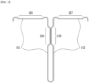
- Fig. 2 is a diagram showing a heat dispersion member included in the heat dissipation member of Fig. 1 .
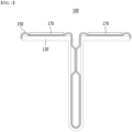
- Fig. 3 is a diagram showing a cross section of the heat dispersion member of Fig. 2 .
- Fig. 4 is a diagram showing a state in which a heat dispersion member and a heat insulation member included in the heat dissipation member of Fig. 1 are coupled.
- Fig. 5 is a diagram showing a state in which a cooling member to the heat dispersion member and the heat insulation member of Fig. 4 are coupled to form a heat dissipation member.
- the heat dissipation member 100 may include a heat dispersion member 150 including a first heat dispersion part 151 and a second heat dispersion part 152.
- the heat dispersion member 150 may include a first heat dispersion part 151 and a second heat dispersion part 152 that are integrally formed. At this time, the first heat dispersion part 151 and the second heat dispersion part 152 may be formed so as to be partially spaced apart from each other. Therefore, a space may be formed between the first heat dispersion part 151 and the second heat dispersion part 152.
- the first heat dispersion part 151 and the second heat dispersion part 152 may be respectively bent and extended, and the directions in which the first heat dispersion part 151 and the second heat dispersion part 152 are bent may be directions opposite to each other.
- the first heat dispersion part 151 may refer to the left area with respect to the center of the heat dispersion member 150 (see Fig. 3 )
- the second heat dispersion part 152 may refer to the right area. Therefore, as being away from a heat dispersion member 150 in which the first heat dispersion part 151 and the second heat dispersion part 152 are integrated, the first heat dispersion part 151 and the second heat dispersion part 152 may have bent portions. Therefore, as being bent as described above, the first heat dispersion part 151 and the second heat dispersion part 152 may have portions bent and extended in directions opposite to each other.
- the heat dissipation member 100 may further include a first depressed part 156 formed in the first heat dispersion part 151, and a second depressed part 157 formed in the second heat dispersion part 152.
- the first depressed part 156 may be formed in the bent and extended portion of the first heat dispersion part 151
- the second depressed part 157 may be formed in the bent and extended portion of the second heat dispersion part 152.
- the heat dissipation member 100 may further include a first indented part 158 formed in the first heat dispersion part 151 and a second indented part 159 formed in the second heat dispersion part 152.
- the first indented part 158 and the second indented part 159 may be formed adjacent to the lower end of the heat dispersion member 150 where the first heat dispersion part 151 and the second heat dispersion part 152 are integrated.
- the first indented part 158 and the second indented part 159 may be formed so as to contact each other.
- heat transferred to the first heat dispersion part 151 or the second heat dispersion part 152 can be rapidly transferred to the second heat dispersion part 152 or the first heat dispersion part 151.
- heat transfer path in the heat dispersion member 150, together with a heat transfer path through the lower end of the heat dissipation member 150 where the first heat dispersion part 151 and the second heat dispersion part 152 are integrated, it is possible to improve the heat dissipation performance of the heat dispersion member 150.
- the heat dissipation member 100 may further include a cooling member 170 formed in the first depressed part 156 and the second depressed part 157.
- the cooling member 170 may be a cooling pad.
- the cooling pad may be formed of a silicon-based or acrylic-based material.
- the cooling pad may be a silicone pad, a silicone rubber pad, a silicone polymer pad, or the like, and may be an acrylic pad, an acrylic polymer pad, or the like, but is not limited thereto.
- the cooling member 170 can cool the heat transferred from the heat dispersion member 150 of the heat dissipation member 100.
- the heat dissipation member 100 may include a heat insulation member 130 that is formed along the outer surface of the heat dispersion member 150.
- the heat insulation member 130 may be formed at a part of the outer surface of the heat dispersion member 150. More specifically, the heat insulation member 130 may be formed on the outer surface of the lower end of the bent and extended portion of the outer surface of the heat dispersion member 150.
- the heat insulation member 130 may not be formed on the inner surface of the heat dispersion member 150.
- a space formed between the first heat dispersion part 151 and the second heat dispersion part 152 of the heat dispersion member 150 may refer to as an inner surface of the heat dispersion member 150. Therefore, the heat insulation member 130 may not be formed on the inner surface of the heat dispersion member 150. This may facilitate heat transfer between the first heat dispersion part 151 and the second heat dispersion part 152 of the heat dispersion member 150.
- the heat insulation member 130 may serve to block the heat propagation of heat moved from one of the heat dispersion parts 151 and 152, the movement of the moved heat to the other heat dispersion parts 152 and 151 may act as a disturbing factor. Therefore, the heat insulation member 130 according to the present embodiment is not formed on the inner surface of the heat dispersion member 150, thereby capable of securing heat transfer between the first heat dispersion part 151 and the second heat dispersion part 152.
- the portion where the heat insulation member 130 is formed may be a portion that is in contact with the module frame 18 of the battery module 10 as will be described later. Therefore, due to the configuration of the heat insulation member 130, it is possible to effectively dissipate the generated heat while preventing heat transfer to adjacent battery modules 10 when the battery module 10 catches fire.
- the heat dispersion member 150 may be made of a material such as aluminum (Al) or graphite.
- the material of the heat dispersion member 150 is not limited thereto, and any material having high thermal conductivity may be included in the present embodiment.
- the heat insulation member 130 may include a ceramic material.
- the ceramic material may be made of a material such as ceramic fiber.
- the material of the heat insulation member 130 is not limited thereto, and any material having high heat insulating properties may be included in the present embodiment.
- a battery pack according to another embodiment of the present disclosure will be described with reference to Figs. 6 to 8 . It can include all the contents of the heat dissipation member described above.
- Fig. 6 is a diagram showing a battery pack according to another embodiment of the present disclosure.
- Fig. 7 is a diagram showing a battery pack according to another embodiment of the present disclosure.
- Fig. 8 is a perspective view showing a battery module included in the battery pack of Figs. 6 and 7 .
- the battery pack 1000 includes a plurality of battery modules 10, a pack frame 1100 that houses the plurality of battery modules 10, and a heat dissipation member 100 located between adjacent battery modules 10 among a plurality of battery modules 10.
- the battery module 10 included in the battery pack 1000 may be configured such that a plurality of battery cells 11 are stacked in a preset direction and then mounted in the module frame 18.
- the plurality of battery cells 11 are not particularly limited in the type thereof, and may be a pouch-type secondary battery or a prismatic secondary battery.
- the heat dissipation member 100 may be a heat dissipation member 100 including all of the features set forth above. That is, the heat dispersion member 150 may include the first heat dispersion part 151 and the second heat dispersion part 152 that are integrally formed. At this time, the first heat dispersion part 151 and the second heat dispersion part 152 may be formed so as to be partially spaced apart from each other. Therefore, a space may be formed between the first heat dispersion part 151 and the second heat dispersion part 152.
- the first heat dispersion part 151 and the second heat dispersion part 152 may be respectively bent and extended, and the directions in which the first heat dispersion part 151 and the second heat dispersion part 152 are bent may be direction opposite to each other.
- the first heat dispersion part 151 may refer to the left area with respect to the center of the heat dispersion member 150 (see Fig. 3 )
- the second heat dispersion part 152 may refer to the right area. Therefore, as being away from a heat dispersion member 150 in which the first heat dispersion part 151 and the second heat dispersion part 152 are integrated, the first heat dispersion part 151 and the second heat dispersion part 152 may have bent portions.
- the first heat dispersion part 151 and the second heat dispersion part 152 may have portions bent and extended in directions opposite to each other.
- the portions bent and extended in directions opposite to each other as described above may be located in the battery pack 1000 so as to be adjacent to the upper part of the battery module 10. That is, the heat dissipation member 100 may be fitted and fixed between the pair of battery modules 10 so that the bent and extended portion of the heat dispersion member 150 is adjacent to the upper part of the battery module 10.
- the heat dissipation member 100 may further include a first depressed part 156 formed in the first heat dispersion part 151, and a second depressed part 157 formed in the second heat dispersion part 152.
- the first depressed part 156 may be formed in the bent and extended portion of the first heat dispersion part 151
- the second depressed part 157 may be formed in the bent and extended portion of the second heat dispersion part 152.
- the first depressed part 156 and the second depressed part 157 may be formed so as to be adjacent to the upper part of the battery module 10.
- the heat dissipation member 100 may further include a first indented part 158 formed in the first heat dispersion part 151, and a second indented part 159 formed in the second heat dispersion part 152.
- the first indented part 158 and the second indented part 159 may be formed adjacent to the lower end of the heat dispersion member 150 where the first heat dispersion part 151 and the second heat dispersion part 152 are integrated. That is, the first indented part 158 and the second indented part 159 may be formed so as to be located between the pair of battery modules 10, and more specifically, it may be formed so as to be adjacent to the side surface part of the module frame 18 of the battery module 10.
- the first indented part 158 and the second indented part 159 may be formed so as to contact each other.
- the heat transferred to the first heat dispersion part 151 or the second heat dispersion part 152 may be rapidly transferred to the second heat dispersion part 152 or the first heat dispersion part 151. That is, by making it possible to form an additional heat transfer path in the heat dispersion member 150 through the contact, together with the heat transfer path through the lower end of the heat dispersion member 150 where the first heat dispersion part 151 and the second heat dispersion part 152 are integrated, it is possible to improve the heat dissipation performance of the heat dispersion member 150.
- the heat dispersion member 150 may be made of a material such as aluminum (Al) or graphite.
- the material of the heat dispersion member 150 is not limited thereto, and any material having high thermal conductivity may be included in the present embodiment.
- the heat dissipation member 100 may further include a cooling member 170 formed in the first depressed part 156 and the second depressed part 157.
- the cooling member 170 may be a cooling pad.
- the cooling member 170 can cool the heat transferred from the heat dispersion member 150 of the heat dissipation member 100.
- the cooling member 170 according to the present embodiment may be in contact with the upper part 1100a of the pack frame 1100. More specifically, the cooling member 170 may be in contact with the inner surface of the upper part 1 100a of the pack frame 1100. Therefore, when the battery module 10 catches fire, thermal energy may be rapidly transferred through the heat dissipation member 100 and the upper portion 1100a of the pack frame 1100 and discharged to the outside.
- the heat dissipation member 100 may include a heat insulation member 130 that is formed along the outer surface of the heat dispersion member 150.
- the heat insulation member 130 may be formed at a part of the outer surface of the heat dispersion member 150. More specifically, the heat insulation member 130 may be formed on the outer surface of the lower end of the bent and extended portion of the outer surface of the heat dispersion member 150.
- the heat insulation member 130 may include a ceramic material.
- the ceramic material may be made of a material such as ceramic fiber.
- the material of the heat insulation member 130 is not limited thereto, and any material having high heat insulating properties may be included in the present embodiment.
- the heat insulating member 130 of the heat dissipation member 100 may be formed between the heat dispersion member 150 and the battery module 10. More specifically, one side surface of one battery module 10 among the pair of battery modules 10 may be in contact with the heat insulation member 130, and one side surface of another battery modules 10 among the pair of battery modules 10 may also be in contact with the heat insulation member 130. Therefore, the heat insulation member 130 may be formed so as contact with the battery module 10.
- heat transfer between adjacent battery modules 10 can be blocked by the heat insulation member 130 of the heat dissipation member 100, thereby preventing continuous ignition or explosion due to heat propagation between adjacent battery modules 10.
- the battery pack 1000 may further include a thermal conductive resin layer 1200 that is formed between the lower part of the battery module 10 and the bottom part 1100b of the pack frame 1100.
- the battery pack 1000 may further include a heat sink 1300 that is formed between the thermal conductive resin layer 1200 and the bottom part 1100b of the pack frame 1100. Therefore, the heat generated in the battery module 10 can be transmitted to not only the heat dissipation member 100 but also the bottom part 1100b of the pack frame 1100 through the thermal conductive resin layer 1200 and the heat sink 1300 and discharged to the outside.
- the battery pack can be applied to various devices.
- a device can be applied to vehicle means such as an electric bike, an electric vehicle, and a hybrid electric vehicle, but the present disclosure is not limited thereto, and is applicable to various devices that can use a battery module, which also falls under the scope of the present disclosure.
Landscapes
- Chemical & Material Sciences (AREA)
- Chemical Kinetics & Catalysis (AREA)
- Electrochemistry (AREA)
- General Chemical & Material Sciences (AREA)
- Engineering & Computer Science (AREA)
- Manufacturing & Machinery (AREA)
- Health & Medical Sciences (AREA)
- Public Health (AREA)
- Business, Economics & Management (AREA)
- Emergency Management (AREA)
- Battery Mounting, Suspending (AREA)
- Secondary Cells (AREA)
Abstract
Description
- This application claims the benefit of
Korean Patent Application No. 10- 2021-0156869 filed on November 15, 2021 - The present disclosure relates to a heat dissipation member and a battery pack including the same, and more particularly to a heat dissipation member that can effectively dissipate heat while preventing heat propagation between adj acent battery modules, and a battery pack including the same.
- As mobile device technology continues to develop and demand therefor continues to increase, demand for secondary batteries as energy sources is rapidly increasing. In particular, a secondary battery has attracted considerable attention as an energy source for power-driven devices, such as an electric bicycle, an electric vehicle, and a hybrid electric vehicle, as well as an energy source for mobile devices, such as a mobile phone, a digital camera, a laptop computer and a wearable device.
- In small mobile devices, one, or two, or three battery cells are used per device, while middle or large-sized devices such as vehicles require high power and large capacity. Therefore, a middle or large-sized battery module having a plurality of battery cells electrically connected to one another is used.
- Since it is preferable for middle or large-sized battery modules to be manufactured with as small a size and weight as possible, a prismatic battery, a pouch-type battery, or the like, which can be stacked with high integration and has a small weight relative to capacity, is mainly used as a battery cell of the middle or large-sized battery modules.
- However, the battery pack of the prior art may include a plurality of battery modules. When a part of the battery cells of the respective battery modules is thermally runaway and ignites or explodes, heat or flame is transmitted to the adjacent secondary battery, which causes occurrence of a secondary explosion or the like, and thus efforts to prevent secondary ignition or explosion increase.
- Therefore, there is a need to develop a heat dissipation member that can effectively dissipate the generated heat while preventing heat transfer to adjacent battery modules when some battery modules in a battery pack ignite and then explode.
- It is an object of the present disclosure to provide a heat dissipation member that can effectively dissipate heat while preventing heat propagation between adjacent battery modules, and a battery pack including the same.
- However, the problem to be solved by the embodiments of the present disclosure is not limited to the above-described problems, and can be variously expanded within the scope of the technical idea included in the present disclosure.
- According to one embodiment of the present disclosure, there is provided a heat dissipation member comprising: a heat dispersion member including a first heat dispersion part and a second heat dispersion part; and a heat insulating member formed along an outer surface of the heat dispersion member.
- The first heat dispersion part and the second heat dispersion part are integrally formed, and the first heat dispersion part and the second heat dispersion part may be formed so as to be partially spaced apart from each other.
- The first heat dispersion part and the second heat dispersion part are respectively bent and extended, and the directions in which the first heat dispersion part and the second heat dispersion part are bent may be directions opposite to each other.
- The heat dissipation member may further comprise a first depressed part formed in the first heat dispersion part, and a second depressed part formed in the second heat dispersion part.
- The heat dissipation member may further comprise a cooling member formed in the first depressed part and the second depressed part.
- The heat dissipation member may further comprise a first indented part formed in the first heat dispersion part; and a second indented part formed in the second heat dispersion part, wherein the first indented part and the second indented part may be formed so as to contact each other.
- According to another embodiment of the present disclosure, there is provided a battery pack comprising: a plurality of battery modules; and a heat dissipation member located between adjacent battery modules among the plurality of battery modules, wherein the heat dissipation member comprises a heat dispersion member including a first heat dispersion part and a second heat dispersion part; and a heat insulation member formed along an outer surface of the heat dispersion member.
- The heat insulation member may be formed between the heat dispersion member and the battery module.
- The heat insulation member may be formed so as to be in contact with the battery module.
- In the battery pack, the first heat dispersion part and the second heat dispersion part are integrally formed, and the first heat dispersion part and the second heat dispersion part may be formed so as to be partially spaced apart from each other
In the battery pack, the first heat dispersion part and the second heat dispersion part are respectively bent and extended, and the directions in which the first heat dispersion part and the second heat dispersion part are bent may be directions opposite to each other. - The battery pack further comprises a first indented part formed in the first heat dispersion part; and a second indented part formed in the second heat dispersion part, wherein the first indented part and the second indented part may be formed so as to contact each other.
- The battery pack may further comprise a first depressed part formed in the first heat dispersion part, and a second depressed part formed in the second heat dispersion part.
- The battery pack may further comprise a cooling member formed in the first depressed part and the second depressed part.
- The battery pack further comprise a pack frame that houses the plurality of battery modules, wherein the cooling member may be in contact with the upper part of the pack frame.
- The cooling member may be in contact with the upper inner surface of the pack frame.
- The battery pack according to yet another embodiment of the present disclosure may further comprise a thermal conductive resin layer formed between a lower part of the battery module and a bottom part of the pack frame.
- The battery pack may further comprise a heat sink formed between a lower part of the thermal conductive resin layer and a bottom part of the pack frame.
- According to embodiments of the present disclosure, in the heat dissipation member and a battery pack including the same, the heat dispersion member included in the heat dissipation member is located between the heat insulation members, and a separation space is formed between the respective heat dispersion members, thereby capable of effectively dissipating heat while preventing heat propagation between the battery modules.
- The effects of the present disclosure are not limited to the effects mentioned above and additional other effects not described above will be clearly understood from the detailed description and the appended drawings by those skilled in the art.
-
-
Fig. 1 is a perspective view showing a heat dissipation member according to one embodiment of the present disclosure; -
Fig. 2 is a diagram showing a heat dispersion member included in the heat dissipation member ofFig. 1 ; -
Fig. 3 is a diagram showing a cross section of the heat dispersion member ofFig. 2 ; -
Fig. 4 is a diagram showing a state in which a heat dispersion member and a heat insulation member included in the heat dissipation member ofFig. 1 are coupled; -
Fig. 5 is a diagram showing a state in which a cooling member to the heat dispersion member and the heat insulation member ofFig. 4 are coupled to form a heat dissipation member; -
Fig. 6 is a diagram showing a battery pack according to another embodiment of the present disclosure; -
Fig. 7 is a diagram showing a battery pack according to another embodiment of the present disclosure; and -
Fig. 8 is a perspective view showing a battery module included in the battery pack ofFigs. 6 and7 . - Hereinafter, various embodiments of the present disclosure will be described in detail with reference to the accompanying drawings so that those skilled in the art can easily carry out them. The present disclosure may be modified in various different ways, and is not limited to the embodiments set forth herein.
- Portions that are irrelevant to the description will be omitted to clearly describe the present disclosure, and like reference numerals designate like elements throughout the description.
- Further, in the drawings, the size and thickness of each element are arbitrarily illustrated for convenience of description, and the present disclosure is not necessarily limited to those illustrated in the drawings. In the drawings, the thickness of layers, areas, etc. are exaggerated for clarity. In the drawings, for convenience of description, the thicknesses of some layers and areas are exaggerated.
- In addition, it will be understood that when an element such as a layer, film, region, or plate is referred to as being "on" or "above" another element, it can be directly on the other element or intervening elements may also be present. In contrast, when an element is referred to as being "directly on" another element, it means that other intervening elements are not present. Further, the word "on" or "above" means arranged on or below a reference portion, and does not necessarily mean being arranged on the upper end of the reference portion toward the opposite direction of gravity.
- Further, throughout the description, when a portion is referred to as "including" a certain component, it means that the portion can further include other components, without excluding the other components, unless otherwise stated.
- Further, throughout the description, when referred to as "planar", it means when a target portion is viewed from the upper side, and when referred to as "cross-sectional", it means when a target portion is viewed from the side of a cross section cut vertically.
- The terms "first," "second," etc. are used to explain various components, but the components should not be limited by the terms. These terms are only used to distinguish one component from the other component.
- Hereinafter, a heat dissipation member according to one embodiment of the present disclosure will be described with reference to
Figs. 1 to 5 . -
Fig. 1 is a perspective view showing a heat dissipation member according to one embodiment of the present disclosure.Fig. 2 is a diagram showing a heat dispersion member included in the heat dissipation member ofFig. 1 .Fig. 3 is a diagram showing a cross section of the heat dispersion member ofFig. 2 .Fig. 4 is a diagram showing a state in which a heat dispersion member and a heat insulation member included in the heat dissipation member ofFig. 1 are coupled.Fig. 5 is a diagram showing a state in which a cooling member to the heat dispersion member and the heat insulation member ofFig. 4 are coupled to form a heat dissipation member. - Referring to
Fig. 1 , theheat dissipation member 100 according to the present embodiment may include aheat dispersion member 150 including a firstheat dispersion part 151 and a secondheat dispersion part 152. - The
heat dispersion member 150 may include a firstheat dispersion part 151 and a secondheat dispersion part 152 that are integrally formed. At this time, the firstheat dispersion part 151 and the secondheat dispersion part 152 may be formed so as to be partially spaced apart from each other. Therefore, a space may be formed between the firstheat dispersion part 151 and the secondheat dispersion part 152. - The first
heat dispersion part 151 and the secondheat dispersion part 152 may be respectively bent and extended, and the directions in which the firstheat dispersion part 151 and the secondheat dispersion part 152 are bent may be directions opposite to each other. Specifically, the firstheat dispersion part 151 may refer to the left area with respect to the center of the heat dispersion member 150 (seeFig. 3 ), and the secondheat dispersion part 152 may refer to the right area. Therefore, as being away from aheat dispersion member 150 in which the firstheat dispersion part 151 and the secondheat dispersion part 152 are integrated, the firstheat dispersion part 151 and the secondheat dispersion part 152 may have bent portions. Therefore, as being bent as described above, the firstheat dispersion part 151 and the secondheat dispersion part 152 may have portions bent and extended in directions opposite to each other. - Meanwhile, referring to
Figs. 2 and3 , theheat dissipation member 100 according to the present embodiment may further include a firstdepressed part 156 formed in the firstheat dispersion part 151, and a seconddepressed part 157 formed in the secondheat dispersion part 152. At this time, the firstdepressed part 156 may be formed in the bent and extended portion of the firstheat dispersion part 151, and the seconddepressed part 157 may be formed in the bent and extended portion of the secondheat dispersion part 152. - Further, the
heat dissipation member 100 may further include a firstindented part 158 formed in the firstheat dispersion part 151 and a secondindented part 159 formed in the secondheat dispersion part 152. At this time, the firstindented part 158 and the secondindented part 159 may be formed adjacent to the lower end of theheat dispersion member 150 where the firstheat dispersion part 151 and the secondheat dispersion part 152 are integrated. In particular, the firstindented part 158 and the secondindented part 159 may be formed so as to contact each other. As the firstindented part 158 and the secondindented part 159 are in contact with each other, heat transferred to the firstheat dispersion part 151 or the secondheat dispersion part 152 can be rapidly transferred to the secondheat dispersion part 152 or the firstheat dispersion part 151. Thereby, by making it possible to form an additional heat transfer path in theheat dispersion member 150, together with a heat transfer path through the lower end of theheat dissipation member 150 where the firstheat dispersion part 151 and the secondheat dispersion part 152 are integrated, it is possible to improve the heat dissipation performance of theheat dispersion member 150. - Further, referring to
Fig. 5 , theheat dissipation member 100 according to the present embodiment may further include a coolingmember 170 formed in the firstdepressed part 156 and the seconddepressed part 157. At this time, the coolingmember 170 may be a cooling pad. The cooling pad may be formed of a silicon-based or acrylic-based material. Specifically, the cooling pad may be a silicone pad, a silicone rubber pad, a silicone polymer pad, or the like, and may be an acrylic pad, an acrylic polymer pad, or the like, but is not limited thereto. The coolingmember 170 can cool the heat transferred from theheat dispersion member 150 of theheat dissipation member 100. - Meanwhile, referring to
Figs. 4 and5 , theheat dissipation member 100 according to the present embodiment may include aheat insulation member 130 that is formed along the outer surface of theheat dispersion member 150. Specifically, theheat insulation member 130 may be formed at a part of the outer surface of theheat dispersion member 150. More specifically, theheat insulation member 130 may be formed on the outer surface of the lower end of the bent and extended portion of the outer surface of theheat dispersion member 150. - The
heat insulation member 130 may not be formed on the inner surface of theheat dispersion member 150. At this time, a space formed between the firstheat dispersion part 151 and the secondheat dispersion part 152 of theheat dispersion member 150 may refer to as an inner surface of theheat dispersion member 150. Therefore, theheat insulation member 130 may not be formed on the inner surface of theheat dispersion member 150. This may facilitate heat transfer between the firstheat dispersion part 151 and the secondheat dispersion part 152 of theheat dispersion member 150. In particular, since theheat insulation member 130 may serve to block the heat propagation of heat moved from one of theheat dispersion parts heat dispersion parts heat insulation member 130 according to the present embodiment is not formed on the inner surface of theheat dispersion member 150, thereby capable of securing heat transfer between the firstheat dispersion part 151 and the secondheat dispersion part 152. - At this time, the portion where the
heat insulation member 130 is formed may be a portion that is in contact with themodule frame 18 of thebattery module 10 as will be described later. Therefore, due to the configuration of theheat insulation member 130, it is possible to effectively dissipate the generated heat while preventing heat transfer toadjacent battery modules 10 when thebattery module 10 catches fire. - In addition, the
heat dispersion member 150 may be made of a material such as aluminum (Al) or graphite. However, the material of theheat dispersion member 150 is not limited thereto, and any material having high thermal conductivity may be included in the present embodiment. - Further, the
heat insulation member 130 may include a ceramic material. In one example, the ceramic material may be made of a material such as ceramic fiber. However, the material of theheat insulation member 130 is not limited thereto, and any material having high heat insulating properties may be included in the present embodiment. - Next, a battery pack according to another embodiment of the present disclosure will be described with reference to
Figs. 6 to 8 . It can include all the contents of the heat dissipation member described above. -
Fig. 6 is a diagram showing a battery pack according to another embodiment of the present disclosure.Fig. 7 is a diagram showing a battery pack according to another embodiment of the present disclosure.Fig. 8 is a perspective view showing a battery module included in the battery pack ofFigs. 6 and7 . - Referring to
Figs. 6 to 8 , thebattery pack 1000 according to the present embodiment includes a plurality ofbattery modules 10, apack frame 1100 that houses the plurality ofbattery modules 10, and aheat dissipation member 100 located betweenadjacent battery modules 10 among a plurality ofbattery modules 10. - First, referring to
Fig. 8 , thebattery module 10 included in thebattery pack 1000 according to the present embodiment may configured such that a plurality ofbattery cells 11 are stacked in a preset direction and then mounted in themodule frame 18. The plurality ofbattery cells 11 are not particularly limited in the type thereof, and may be a pouch-type secondary battery or a prismatic secondary battery. - At this time, the
heat dissipation member 100 may be aheat dissipation member 100 including all of the features set forth above. That is, theheat dispersion member 150 may include the firstheat dispersion part 151 and the secondheat dispersion part 152 that are integrally formed. At this time, the firstheat dispersion part 151 and the secondheat dispersion part 152 may be formed so as to be partially spaced apart from each other. Therefore, a space may be formed between the firstheat dispersion part 151 and the secondheat dispersion part 152. - The first
heat dispersion part 151 and the secondheat dispersion part 152 may be respectively bent and extended, and the directions in which the firstheat dispersion part 151 and the secondheat dispersion part 152 are bent may be direction opposite to each other. Specifically, the firstheat dispersion part 151 may refer to the left area with respect to the center of the heat dispersion member 150 (seeFig. 3 ), and the secondheat dispersion part 152 may refer to the right area. Therefore, as being away from aheat dispersion member 150 in which the firstheat dispersion part 151 and the secondheat dispersion part 152 are integrated, the firstheat dispersion part 151 and the secondheat dispersion part 152 may have bent portions. Therefore, as being bent as described above, the firstheat dispersion part 151 and the secondheat dispersion part 152 may have portions bent and extended in directions opposite to each other. At this time, the portions bent and extended in directions opposite to each other as described above may be located in thebattery pack 1000 so as to be adjacent to the upper part of thebattery module 10. That is, theheat dissipation member 100 may be fitted and fixed between the pair ofbattery modules 10 so that the bent and extended portion of theheat dispersion member 150 is adjacent to the upper part of thebattery module 10. - Meanwhile, the
heat dissipation member 100 according to the present embodiment may further include a firstdepressed part 156 formed in the firstheat dispersion part 151, and a seconddepressed part 157 formed in the secondheat dispersion part 152. At this time, the firstdepressed part 156 may be formed in the bent and extended portion of the firstheat dispersion part 151, and the seconddepressed part 157 may be formed in the bent and extended portion of the secondheat dispersion part 152. In particular, the firstdepressed part 156 and the seconddepressed part 157 may be formed so as to be adjacent to the upper part of thebattery module 10. - In addition, the
heat dissipation member 100 may further include a firstindented part 158 formed in the firstheat dispersion part 151, and a secondindented part 159 formed in the secondheat dispersion part 152. At this time, the firstindented part 158 and the secondindented part 159 may be formed adjacent to the lower end of theheat dispersion member 150 where the firstheat dispersion part 151 and the secondheat dispersion part 152 are integrated. That is, the firstindented part 158 and the secondindented part 159 may be formed so as to be located between the pair ofbattery modules 10, and more specifically, it may be formed so as to be adjacent to the side surface part of themodule frame 18 of thebattery module 10. - At this time, the first
indented part 158 and the secondindented part 159 may be formed so as to contact each other. As the firstindented part 158 and the secondindented part 159 contact with each other, the heat transferred to the firstheat dispersion part 151 or the secondheat dispersion part 152 may be rapidly transferred to the secondheat dispersion part 152 or the firstheat dispersion part 151. That is, by making it possible to form an additional heat transfer path in theheat dispersion member 150 through the contact, together with the heat transfer path through the lower end of theheat dispersion member 150 where the firstheat dispersion part 151 and the secondheat dispersion part 152 are integrated, it is possible to improve the heat dissipation performance of theheat dispersion member 150. - In addition, the
heat dispersion member 150 may be made of a material such as aluminum (Al) or graphite. However, the material of theheat dispersion member 150 is not limited thereto, and any material having high thermal conductivity may be included in the present embodiment. - At this time, the
heat dissipation member 100 according to the present embodiment may further include a coolingmember 170 formed in the firstdepressed part 156 and the seconddepressed part 157. At this time, the coolingmember 170 may be a cooling pad. The coolingmember 170 can cool the heat transferred from theheat dispersion member 150 of theheat dissipation member 100. Further, the coolingmember 170 according to the present embodiment may be in contact with theupper part 1100a of thepack frame 1100. More specifically, the coolingmember 170 may be in contact with the inner surface of the upper part 1 100a of thepack frame 1100. Therefore, when thebattery module 10 catches fire, thermal energy may be rapidly transferred through theheat dissipation member 100 and theupper portion 1100a of thepack frame 1100 and discharged to the outside. - Meanwhile, referring to
Figs. 4 and5 , theheat dissipation member 100 according to the present embodiment may include aheat insulation member 130 that is formed along the outer surface of theheat dispersion member 150. Specifically, theheat insulation member 130 may be formed at a part of the outer surface of theheat dispersion member 150. More specifically, theheat insulation member 130 may be formed on the outer surface of the lower end of the bent and extended portion of the outer surface of theheat dispersion member 150. - Further, the
heat insulation member 130 may include a ceramic material. In one example, the ceramic material may be made of a material such as ceramic fiber. However, the material of theheat insulation member 130 is not limited thereto, and any material having high heat insulating properties may be included in the present embodiment. - Further, according to the present embodiment, the
heat insulating member 130 of theheat dissipation member 100 may be formed between theheat dispersion member 150 and thebattery module 10. More specifically, one side surface of onebattery module 10 among the pair ofbattery modules 10 may be in contact with theheat insulation member 130, and one side surface of anotherbattery modules 10 among the pair ofbattery modules 10 may also be in contact with theheat insulation member 130. Therefore, theheat insulation member 130 may be formed so as contact with thebattery module 10. - Thus, in the present embodiment, when some battery modules ignite or explode, heat transfer between
adjacent battery modules 10 can be blocked by theheat insulation member 130 of theheat dissipation member 100, thereby preventing continuous ignition or explosion due to heat propagation betweenadjacent battery modules 10. - In addition, referring to
Fig. 7 , thebattery pack 1000 according to another embodiment of the present disclosure may further include a thermalconductive resin layer 1200 that is formed between the lower part of thebattery module 10 and the bottom part 1100b of thepack frame 1100. Moreover, thebattery pack 1000 may further include aheat sink 1300 that is formed between the thermalconductive resin layer 1200 and the bottom part 1100b of thepack frame 1100. Therefore, the heat generated in thebattery module 10 can be transmitted to not only theheat dissipation member 100 but also the bottom part 1100b of thepack frame 1100 through the thermalconductive resin layer 1200 and theheat sink 1300 and discharged to the outside. - The battery pack can be applied to various devices. Such a device can be applied to vehicle means such as an electric bike, an electric vehicle, and a hybrid electric vehicle, but the present disclosure is not limited thereto, and is applicable to various devices that can use a battery module, which also falls under the scope of the present disclosure.
- Although preferred embodiments of the present disclosure have been described in detail above, the scope of the present disclosure is not limited thereto, and numerous other modifications and embodiments can be devised by those skilled in the art, without departing from the spirit and scope of the principles of the invention described in the appended claims. Further, these modifications should not be understood individually from the technical spirit or perspective of the present disclosure.
-
- 10: battery module
- 100: heat dissipation member
- 130: heat insulation member
- 150: heat dispersion member
- 151: first heat dispersion part
- 152: second heat dispersion part
- 156: first depressed part
- 157: second depressed part
- 158: first indented part
- 159: second indented part
- 170: cooling member
- 1000: battery pack
- 1100: pack frame
- 1100a: upper part of the pack frame
- 1100b: bottom part of the pack frame
- 1200: thermal conductive resin layer
- 1300: heat sink
Claims (18)
- A heat dissipation member comprising:a heat dispersion member including a first heat dispersion part and a second heat dispersion part; anda heat insulating member formed along an outer surface of the heat dispersion member.
- The heat dissipation member according to claim 1 wherein:the first heat dispersion part and the second heat dispersion part are integrally formed, andthe first heat dispersion part and the second heat dispersion part are formed so as to be partially spaced apart from each other.
- The heat dissipation member according to claim 1 wherein:the first heat dispersion part and the second heat dispersion part are respectively bent and extended, andthe directions in which the first heat dispersion part and the second heat dispersion part are bent are directions opposite to each other.
- The heat dissipation member according to claim 1, further comprising:a first depressed part formed in the first heat dispersion part, anda second depressed part formed in the second heat dispersion part.
- The heat dissipation member according to claim 4, further comprising:
a cooling member formed in the first depressed part and the second depressed part. - The heat dissipation member according to claim 1, further comprising:a first indented part formed in the first heat dispersion part; anda second indented part formed in the second heat dispersion part,wherein the first indented part and the second indented part are formed so as to contact each other.
- A battery pack comprising:a plurality of battery modules; anda heat dissipation member located between adjacent battery modules among the plurality of battery modules,wherein the heat dissipation member comprises,a heat dispersion member including a first heat dispersion part and a second heat dispersion part; anda heat insulation member formed along an outer surface of the heat dissipation member.
- The battery pack according to claim 7 wherein:
the heat insulation member is formed between the heat dispersion member and the battery module. - The battery pack according to claim 7 wherein:
the heat insulation member is formed so as to be in contact with the battery module. - The battery pack according to claim 7 wherein:the first heat dispersion part and the second heat dispersion part are integrally formed, andthe first heat dispersion part and the second heat dispersion part are formed so as to be partially spaced apart from each other
- The battery pack according to claim 7 wherein:the first heat dispersion part and the second heat dispersion part are respectively bent and extended, andthe directions in which the first heat dispersion part and the second heat dispersion part are bent are directions opposite to each other.
- The battery pack according to claim 7, further comprising:a first indented part formed in the first heat dispersion part; anda second indented part formed in the second heat dispersion part,wherein the first indented part and the second indented part are formed so as to contact each other.
- The battery pack according to claim 7, further comprising:a first depressed part formed in the first heat dispersion part, anda second depressed part formed in the second heat dispersion part.
- The battery pack according to claim 13, further comprising:
a cooling member formed in the first depressed part and the second depressed part. - The battery pack according to claim 14, further comprising:a pack frame that houses the plurality of battery modules,wherein the cooling member is in contact with the upper part of the pack frame.
- The battery pack according to claim 14 wherein:
the cooling member is in contact with the upper inner surface of the pack frame. - The battery pack according to claim 14, further comprising:
a thermal conductive resin layer formed between a lower part of the battery module and a bottom part of the pack frame. - The battery pack according to claim 17, further comprising:
a heat sink formed between a lower part of the thermal conductive resin layer and a bottom part of the pack frame.
Applications Claiming Priority (2)
| Application Number | Priority Date | Filing Date | Title |
|---|---|---|---|
| KR1020210156869A KR20230070860A (en) | 2021-11-15 | 2021-11-15 | Flame arrester and battery pack including the same |
| PCT/KR2022/013134 WO2023085570A1 (en) | 2021-11-15 | 2022-09-01 | Heat dissipation member and battery pack including same |
Publications (2)
| Publication Number | Publication Date |
|---|---|
| EP4246667A1 true EP4246667A1 (en) | 2023-09-20 |
| EP4246667A4 EP4246667A4 (en) | 2024-12-04 |
Family
ID=86336264
Family Applications (1)
| Application Number | Title | Priority Date | Filing Date |
|---|---|---|---|
| EP22892993.1A Pending EP4246667A4 (en) | 2021-11-15 | 2022-09-01 | HEAT DISSIPATION ELEMENT AND BATTERY PACK COMPRISING SAME |
Country Status (6)
| Country | Link |
|---|---|
| US (1) | US20240055688A1 (en) |
| EP (1) | EP4246667A4 (en) |
| JP (1) | JP7674044B2 (en) |
| KR (1) | KR20230070860A (en) |
| CN (1) | CN116686140A (en) |
| WO (1) | WO2023085570A1 (en) |
Family Cites Families (13)
| Publication number | Priority date | Publication date | Assignee | Title |
|---|---|---|---|---|
| EP2479835B1 (en) * | 2009-09-15 | 2017-01-11 | LG Chem, Ltd. | Battery module having a temperature sensor installed thereon, and medium or large battery pack including same |
| WO2011092773A1 (en) * | 2010-01-29 | 2011-08-04 | パナソニック株式会社 | Cell module |
| TWI382572B (en) * | 2010-02-12 | 2013-01-11 | Asia Vital Components Co Ltd | Used in the heating structure of the battery and the device and cooling auxiliary module |
| JP5871067B2 (en) * | 2012-07-13 | 2016-03-01 | 日産自動車株式会社 | Battery structure |
| KR20150127863A (en) * | 2012-08-30 | 2015-11-18 | 에스케이이노베이션 주식회사 | Battery module |
| JP2017027720A (en) * | 2015-07-21 | 2017-02-02 | カルソニックカンセイ株式会社 | Battery cooling structure |
| CN108054460B (en) * | 2016-11-29 | 2021-03-05 | 北京科易动力科技有限公司 | Heat absorption and heat insulation structure of battery module |
| KR102172517B1 (en) * | 2017-04-04 | 2020-10-30 | 주식회사 엘지화학 | Battery Pack having crash beam structure |
| CN111033876B (en) * | 2018-01-25 | 2024-05-28 | 松下知识产权经营株式会社 | Battery pack |
| US11721867B2 (en) * | 2018-02-27 | 2023-08-08 | Panasonic Intellectual Property Management Co., Ltd. | Battery module and battery pack |
| KR102687619B1 (en) * | 2018-12-05 | 2024-07-24 | 주식회사 엘지에너지솔루션 | Battery module |
| JP2020113387A (en) * | 2019-01-09 | 2020-07-27 | 信越ポリマー株式会社 | Heat dissipation structure and battery with the same |
| JP2021163538A (en) * | 2020-03-30 | 2021-10-11 | 日東電工株式会社 | Heat insulating material and battery |
-
2021
- 2021-11-15 KR KR1020210156869A patent/KR20230070860A/en active Pending
-
2022
- 2022-09-01 US US18/267,494 patent/US20240055688A1/en active Pending
- 2022-09-01 WO PCT/KR2022/013134 patent/WO2023085570A1/en not_active Ceased
- 2022-09-01 CN CN202280008939.5A patent/CN116686140A/en active Pending
- 2022-09-01 JP JP2023534033A patent/JP7674044B2/en active Active
- 2022-09-01 EP EP22892993.1A patent/EP4246667A4/en active Pending
Also Published As
| Publication number | Publication date |
|---|---|
| JP7674044B2 (en) | 2025-05-09 |
| JP2023554265A (en) | 2023-12-27 |
| WO2023085570A1 (en) | 2023-05-19 |
| CN116686140A (en) | 2023-09-01 |
| US20240055688A1 (en) | 2024-02-15 |
| KR20230070860A (en) | 2023-05-23 |
| EP4246667A4 (en) | 2024-12-04 |
Similar Documents
| Publication | Publication Date | Title |
|---|---|---|
| KR102949547B1 (en) | A battery pack with thermal propagation prevention structure between battery modules | |
| CN110720158A (en) | Multilayer cylindrical battery module with heat dissipation and chain burning prevention structure and battery pack containing the same | |
| KR102284606B1 (en) | Pouch for secondary battery, Secondary battery and Battery module including the secondary battery | |
| US12531266B2 (en) | Battery module and battery pack including the same | |
| KR20160147565A (en) | Cooling Apparatus for Battery Cell | |
| EP4040575A1 (en) | Battery module and battery pack including same | |
| JP2021501959A (en) | Battery module and battery pack containing it | |
| CN114930616A (en) | Battery module and method for manufacturing same | |
| KR20220049870A (en) | Battery module and battery pack including the same | |
| KR20220147516A (en) | Battery pack and device including the same | |
| WO2022124731A1 (en) | Battery pack, and device including same | |
| US20240055688A1 (en) | Heat Dissipation Member and Battery Pack Including Same | |
| US20230369672A1 (en) | Heat dissipation member and battery pack including the same | |
| US12629550B2 (en) | Flame arrester and battery pack including the same | |
| US20240216733A1 (en) | Flame arrester and battery pack including the same | |
| EP4181274A1 (en) | Battery module and battery pack including same | |
| US20240014460A1 (en) | Battery pack and device including the same | |
| CN223884513U (en) | Battery pack and device comprising same | |
| KR20230097703A (en) | Heat dissipation member and battery pack including the same | |
| JP2024529335A (en) | Battery cell, battery module, battery pack and automobile including same | |
| KR20230036864A (en) | Battery module and battery pack including the same | |
| EP4648181A1 (en) | Battery module and battery pack including same | |
| CN117882244A (en) | Battery cell, battery module including the battery cell, battery pack and vehicle |
Legal Events
| Date | Code | Title | Description |
|---|---|---|---|
| STAA | Information on the status of an ep patent application or granted ep patent |
Free format text: STATUS: THE INTERNATIONAL PUBLICATION HAS BEEN MADE |
|
| PUAI | Public reference made under article 153(3) epc to a published international application that has entered the european phase |
Free format text: ORIGINAL CODE: 0009012 |
|
| STAA | Information on the status of an ep patent application or granted ep patent |
Free format text: STATUS: REQUEST FOR EXAMINATION WAS MADE |
|
| 17P | Request for examination filed |
Effective date: 20230614 |
|
| AK | Designated contracting states |
Kind code of ref document: A1 Designated state(s): AL AT BE BG CH CY CZ DE DK EE ES FI FR GB GR HR HU IE IS IT LI LT LU LV MC MK MT NL NO PL PT RO RS SE SI SK SM TR |
|
| A4 | Supplementary search report drawn up and despatched |
Effective date: 20241104 |
|
| RIC1 | Information provided on ipc code assigned before grant |
Ipc: H01M 10/6556 20140101ALI20241028BHEP Ipc: H01M 10/6555 20140101ALI20241028BHEP Ipc: H01M 10/6551 20140101ALI20241028BHEP Ipc: H01M 50/289 20210101ALI20241028BHEP Ipc: H01M 10/653 20140101ALI20241028BHEP Ipc: H01M 50/204 20210101ALI20241028BHEP Ipc: H01M 10/613 20140101ALI20241028BHEP Ipc: H01M 10/658 20140101ALI20241028BHEP Ipc: H01M 10/655 20140101AFI20241028BHEP |
|
| DAV | Request for validation of the european patent (deleted) | ||
| DAX | Request for extension of the european patent (deleted) | ||
| STAA | Information on the status of an ep patent application or granted ep patent |
Free format text: STATUS: EXAMINATION IS IN PROGRESS |
|
| 17Q | First examination report despatched |
Effective date: 20250708 |