EP4246656A1 - Battery module pressing test device and method - Google Patents
Battery module pressing test device and method Download PDFInfo
- Publication number
- EP4246656A1 EP4246656A1 EP22837953.3A EP22837953A EP4246656A1 EP 4246656 A1 EP4246656 A1 EP 4246656A1 EP 22837953 A EP22837953 A EP 22837953A EP 4246656 A1 EP4246656 A1 EP 4246656A1
- Authority
- EP
- European Patent Office
- Prior art keywords
- pressure
- battery cells
- module case
- battery
- module
- Prior art date
- Legal status (The legal status is an assumption and is not a legal conclusion. Google has not performed a legal analysis and makes no representation as to the accuracy of the status listed.)
- Granted
Links
Images




Classifications
-
- H—ELECTRICITY
- H01—ELECTRIC ELEMENTS
- H01M—PROCESSES OR MEANS, e.g. BATTERIES, FOR THE DIRECT CONVERSION OF CHEMICAL ENERGY INTO ELECTRICAL ENERGY
- H01M10/00—Secondary cells; Manufacture thereof
- H01M10/42—Methods or arrangements for servicing or maintenance of secondary cells or secondary half-cells
- H01M10/4285—Testing apparatus
-
- G—PHYSICS
- G01—MEASURING; TESTING
- G01B—MEASURING LENGTH, THICKNESS OR SIMILAR LINEAR DIMENSIONS; MEASURING ANGLES; MEASURING AREAS; MEASURING IRREGULARITIES OF SURFACES OR CONTOURS
- G01B5/00—Measuring arrangements characterised by the use of mechanical techniques
- G01B5/30—Measuring arrangements characterised by the use of mechanical techniques for measuring the deformation in a solid, e.g. mechanical strain gauge
-
- H—ELECTRICITY
- H01—ELECTRIC ELEMENTS
- H01M—PROCESSES OR MEANS, e.g. BATTERIES, FOR THE DIRECT CONVERSION OF CHEMICAL ENERGY INTO ELECTRICAL ENERGY
- H01M10/00—Secondary cells; Manufacture thereof
- H01M10/04—Construction or manufacture in general
- H01M10/0481—Compression means other than compression means for stacks of electrodes and separators
-
- H—ELECTRICITY
- H01—ELECTRIC ELEMENTS
- H01M—PROCESSES OR MEANS, e.g. BATTERIES, FOR THE DIRECT CONVERSION OF CHEMICAL ENERGY INTO ELECTRICAL ENERGY
- H01M10/00—Secondary cells; Manufacture thereof
- H01M10/42—Methods or arrangements for servicing or maintenance of secondary cells or secondary half-cells
- H01M10/44—Methods for charging or discharging
- H01M10/441—Methods for charging or discharging for several batteries or cells simultaneously or sequentially
-
- H—ELECTRICITY
- H01—ELECTRIC ELEMENTS
- H01M—PROCESSES OR MEANS, e.g. BATTERIES, FOR THE DIRECT CONVERSION OF CHEMICAL ENERGY INTO ELECTRICAL ENERGY
- H01M10/00—Secondary cells; Manufacture thereof
- H01M10/42—Methods or arrangements for servicing or maintenance of secondary cells or secondary half-cells
- H01M10/44—Methods for charging or discharging
- H01M10/445—Methods for charging or discharging in response to gas pressure
-
- H—ELECTRICITY
- H01—ELECTRIC ELEMENTS
- H01M—PROCESSES OR MEANS, e.g. BATTERIES, FOR THE DIRECT CONVERSION OF CHEMICAL ENERGY INTO ELECTRICAL ENERGY
- H01M10/00—Secondary cells; Manufacture thereof
- H01M10/42—Methods or arrangements for servicing or maintenance of secondary cells or secondary half-cells
- H01M10/48—Accumulators combined with arrangements for measuring, testing or indicating the condition of cells, e.g. the level or density of the electrolyte
- H01M10/482—Accumulators combined with arrangements for measuring, testing or indicating the condition of cells, e.g. the level or density of the electrolyte for several batteries or cells simultaneously or sequentially
-
- H—ELECTRICITY
- H01—ELECTRIC ELEMENTS
- H01M—PROCESSES OR MEANS, e.g. BATTERIES, FOR THE DIRECT CONVERSION OF CHEMICAL ENERGY INTO ELECTRICAL ENERGY
- H01M50/00—Constructional details or processes of manufacture of the non-active parts of electrochemical cells other than fuel cells, e.g. hybrid cells
- H01M50/20—Mountings; Secondary casings or frames; Racks, modules or packs; Suspension devices; Shock absorbers; Transport or carrying devices; Holders
- H01M50/233—Mountings; Secondary casings or frames; Racks, modules or packs; Suspension devices; Shock absorbers; Transport or carrying devices; Holders characterised by physical properties of casings or racks, e.g. dimensions
- H01M50/242—Mountings; Secondary casings or frames; Racks, modules or packs; Suspension devices; Shock absorbers; Transport or carrying devices; Holders characterised by physical properties of casings or racks, e.g. dimensions adapted for protecting batteries against vibrations, collision impact or swelling
-
- H—ELECTRICITY
- H01—ELECTRIC ELEMENTS
- H01M—PROCESSES OR MEANS, e.g. BATTERIES, FOR THE DIRECT CONVERSION OF CHEMICAL ENERGY INTO ELECTRICAL ENERGY
- H01M50/00—Constructional details or processes of manufacture of the non-active parts of electrochemical cells other than fuel cells, e.g. hybrid cells
- H01M50/20—Mountings; Secondary casings or frames; Racks, modules or packs; Suspension devices; Shock absorbers; Transport or carrying devices; Holders
- H01M50/204—Racks, modules or packs for multiple batteries or multiple cells
-
- H—ELECTRICITY
- H01—ELECTRIC ELEMENTS
- H01M—PROCESSES OR MEANS, e.g. BATTERIES, FOR THE DIRECT CONVERSION OF CHEMICAL ENERGY INTO ELECTRICAL ENERGY
- H01M50/00—Constructional details or processes of manufacture of the non-active parts of electrochemical cells other than fuel cells, e.g. hybrid cells
- H01M50/20—Mountings; Secondary casings or frames; Racks, modules or packs; Suspension devices; Shock absorbers; Transport or carrying devices; Holders
- H01M50/204—Racks, modules or packs for multiple batteries or multiple cells
- H01M50/207—Racks, modules or packs for multiple batteries or multiple cells characterised by their shape
- H01M50/211—Racks, modules or packs for multiple batteries or multiple cells characterised by their shape adapted for pouch cells
-
- Y—GENERAL TAGGING OF NEW TECHNOLOGICAL DEVELOPMENTS; GENERAL TAGGING OF CROSS-SECTIONAL TECHNOLOGIES SPANNING OVER SEVERAL SECTIONS OF THE IPC; TECHNICAL SUBJECTS COVERED BY FORMER USPC CROSS-REFERENCE ART COLLECTIONS [XRACs] AND DIGESTS
- Y02—TECHNOLOGIES OR APPLICATIONS FOR MITIGATION OR ADAPTATION AGAINST CLIMATE CHANGE
- Y02E—REDUCTION OF GREENHOUSE GAS [GHG] EMISSIONS, RELATED TO ENERGY GENERATION, TRANSMISSION OR DISTRIBUTION
- Y02E60/00—Enabling technologies; Technologies with a potential or indirect contribution to GHG emissions mitigation
- Y02E60/10—Energy storage using batteries
Definitions
- the present invention relates to a device and a method for performing a pressure test on a battery module.
- secondary batteries capable of being charged and discharged have been widely used as energy sources for wireless mobile devices.
- the secondary batteries are getting attention as energy sources for electric vehicles and hybrid electric vehicles which are proposed as measures to address the air pollution of conventional gasoline and diesel vehicles using fossil fuels. Therefore, types of applications using the secondary batteries are diversifying due to the advantages of the secondary batteries, and it is expected that the secondary batteries are applied to more fields and products in the future than now.
- Secondary batteries may be classified into lithium ion batteries, lithium ion polymer batteries, and lithium polymer batteries according to the composition of an electrode and an electrolyte, and among these batteries, the use of the lithium ion polymer battery, which is less prone to leakage of the electrolyte and easy to manufacture, is increasing.
- the secondary battery is classified into a cylindrical battery in which an electrode assembly is installed in a cylindrical metal can, a prismatic battery in which an electrode assembly is installed in a prismatic metal can, and a pouch-type battery in which an electrode assembly is installed in a pouch-type case of an aluminum laminated sheet.
- the electrode assembly installed in the battery case is formed with a structure of a positive electrode, a negative electrode, and a separator interposed between the positive electrode and the negative electrode and is a power generation element capable of being charged and discharged.
- the electrode assembly is classified into a jelly-roll type electrode assembly in which a separator is interposed between a positive electrode and a negative electrode, which are long sheets coated with an active material, and is wound, and a stack type electrode assembly in which a plurality of positive and negative electrodes, each having a predetermined size, are sequentially stacked with a separator interposed therebetween.
- an electric vehicle or the like uses high-output electric energy, and thus a plurality of battery modules per vehicle are required.
- the battery module is mounted in a module case.
- the battery module applies stress to the module case as the battery cells in the battery module repeatedly swells according to repeated charging and discharging.
- stress is continuously applied to the module case, fatigue accumulates in a welded portion of the module case, and thus a phenomenon in which the welded portion is damaged occurs. Therefore, it is necessary to perform a simulation test for fatigue evaluation on the welded portion of the module case.
- FIG. 1 is a schematic diagram illustrating a structure of a conventional device for performing a pressure test on a battery module.
- a conventional device 1 for performing a pressure test on a battery module uses a method of directly simulating an actual battery module. Specifically, in the device 1 for performing a pressure test on a battery module, a plurality of battery cells 11 are disposed in parallel in a module case 10, and a buffer pad 20 may be provided between the outermost battery cell and the module case. In addition, welding is performed on the module case to seal and fix the module case, and thus a welded portion 12 is formed.
- a charging/discharging cycle of the battery cell is repeated to swell the battery cell so that a degree of fatigue of the welded portion is measured through the stress applied to the module case.
- the repeated charging and discharging takes a long time, there is a problem in that the performance of one test takes an excessively long time.
- it is difficult to control the degree of swelling of the battery cell and the resulting pressure since the repeated charging and discharging takes a long time, there is a problem in that the performance of one test takes an excessively long time.
- An object of the present invention is to provide a device and a method for performing a pressure test on a battery module, which simulate a pressure due to swelling of a battery cell applied to the module case in a short time and easily control a pressure.
- a device for performing a pressure test on a battery module which includes a module case in which a plurality of battery cells are accommodated, a pressure plate installed in a middle portion of the module case in a width direction and configured to pressure the battery cells toward the module case, a pressure driver configured to apply a pressure to the pressure plate, and a controller configured to control a pressure force and a pressure pattern with respect to the battery cells, wherein the pressure plate simulates expansion and contraction of the battery cells by repeatedly pressurizing and depressurizing the battery cells.
- the pressure plate may pressurize or depressurize the battery cells in the same direction as a swelling direction.
- the pressure driver may include a hydraulic pump and a pressure member connected to the hydraulic pump to pressurize a pressure plate and the battery cells.
- a buffer pad may be disposed between the module case and a battery cell located at an outermost portion among the battery cells accommodated in the module case.
- the device for performing a pressure test on a battery module may further include a pressure sensor configured to measure a pressure applied to an inner surface of the module case facing the battery cells of the module case.
- the device for performing a pressure test on a battery module may further include a displacement sensor located outside the module case and configured to measure a displacement of the module case according to the pressure.
- the pressure plate may be provided as two or more pressure plates disposed in the length direction of the battery cell to pressurize the battery cell with the same pressure or different pressures.
- the pressure member may be provided as two or more pressure members disposed in the length direction of the battery cell to pressurize the battery cells with the same pressure or different pressures.
- the device for performing a pressure test on a battery module may further include a welding fatigue tester configured to test a state of the welded portion formed in the module case.
- the device for performing a pressure test on a battery module may further include a charging/discharging part configured to charge and discharge the plurality of battery cells.
- the charging/discharging part may measure charging/discharging performance of the battery cells according to a pressure condition.
- a method of performing a pressure test on a battery module is provided.
- a method of performing a pressure test on a battery module which includes mounting a plurality of battery cells on the above-described device for performing a pressure test on a battery module, repeatedly pressurizing and depressurizing the battery cells in the same direction as a swelling direction using a pressure plate and simulating expansion and contraction of the battery cells, and measuring a state change of a module case according to the pressurizing and depressurizing of the battery cells.
- the measuring of the state change of the module case may include measuring a displacement of the module case according to pressurizing and depressurizing.
- the measuring of the state change of the module case may include measuring a state change of a welded portion formed in the module case.
- the method of performing a pressure test on a battery module may further include charging and discharging the plurality of battery cells, measuring charging and discharging performance of the battery cell according to a pressure condition, and deriving an optimal pressure level from the charging and discharging performance.
- a pressure plate and a pressure driver which are able to simulate swelling of the battery cell, are installed inside the battery cell, it is possible to simulate that a pressure due to the swelling of the battery cell is applied to the module case in a short time and to apply a pressure of a desired level.
- the terms "comprising,” “having,” and the like are used to specify the presence of a feature, a number, a step, an operation, a component, an element, or a combination thereof described herein, and they do not preclude the presence or addition of one or more other features, numbers, steps, operations, components, elements, or combinations thereof.
- a portion of a layer, a film, a region, a plate, or the like is referred to as being "on” another portion, this includes not only a case in which the portion is “directly on” another portion but also a case in which still another portion is present between the portion and the other portion.
- being disposed “on” may include the case of being disposed not only on an upper portion but also on a lower portion.
- a "length direction” means a direction in which an electrode lead of a battery cell protrudes.
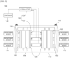
- FIG. 2 is a block diagram illustrating a configuration of the device for performing a pressure test on a battery module according to one embodiment of the present invention
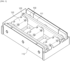
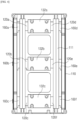
- FIGS. 3 and 4 are schematic diagrams illustrating a structure of the device for performing a pressure test on a battery module according to the present invention.
- a device 100 for performing a pressure test on a battery module includes a module case 110 in which a plurality of battery cells 111 are accommodated, a pressure plate 120 installed in a middle portion of the module case 110 in a width direction and configured to pressure the battery cell 111 toward the module case 110, a pressure driver 130 configured to apply a pressure to the pressure plate 120, and a controller 140 configured to control a pressure force and a pressure pattern with respect to the battery cell 111, and the pressure plate 120 simulates expansion and contraction of the battery cell by repeatedly pressurizing and depressurizing the battery cell 111.
- the pressure plate and the pressure driver which are able to simulate swelling of the battery cell, are installed inside the battery module and artificially pressurize the battery cell, it is possible to simulate that a pressure due to the swelling of the battery cell is applied to the module case in a short time and to apply a pressure of a desired level.
- a device 100 for performing a pressure test on a battery module simulates a general battery module and has a structure in which the battery cell 111 is accommodated in the module case 110.
- the module case 110 may employ the same module case as that used for a general battery module, and a metal material having excellent rigidity, such as iron or stainless steel, may be used, but a type of the material is not limited thereto.
- the battery cell 111 may also employ the same battery cell as that used for a general battery module, and there is no particular limitation on its shape, but in the present invention, a pouch-type battery cell to which a surface pressure can be applied may be used.
- the pouch-type battery cell has a structure in which an electrode assembly is accommodated in a pouch-type battery case, electrode leads are drawn out from one end portion or both end portions of the battery case, and a sealing part is formed on an outer periphery of the battery case.
- a specific content related to other battery cells is known to those skilled in the art, and thus a detailed description thereof will be omitted herein.
- a plurality of battery cells are mounted in the battery module, and as the battery cells are repeatedly charged and discharged, the battery cells swell repeatedly, and due to stress by the swelling, physical damage such as cracks may occur in the welded portion of the module case.
- a pressure part capable of pressurize the battery cell in the module case is provided.
- a pressure plate 120 for pressurizing the battery cell and a pressure driver 130 for applying a pressure to the pressure plate 120 are provided as the pressure part.
- the pressure plate 120 simulates expansion and contraction of the battery cell by repeatedly pressurizing and depressurizing the battery cell 111 and pressurizes or depressurizes the battery cell 111 in the module case 110 in the same direction as a swelling direction. Accordingly, the pressure plate 120 pressurizes or depressurizes the battery cell 111 in a direction perpendicular to a wide surface of the battery case.
- the pressure plate 120 is located in a middle portion of the module case 110. As described below, in order to cover the pressure member located in the middle portion, a pair of pressure plate 120 is located on both sides of the pressure member in an internal space of the module case 110. Accordingly, the pressure plate 120 pressurizes the battery cells in both directions of the module case 110.
- the pressure plate 120 may employ a material without limitation as long as it has a rigid enough not to be easily deformed or damaged even when the battery cell is pressurized and has heat resistance enough not to be damaged due to heat generated from the battery cell.
- the pressure driver 130 applies a pressure to the pressure plate 120.
- the pressure driver 130 may include a hydraulic pump 131 and a pressure member 132 connected to the hydraulic pump 131 and configured to pressurize the pressure plate 120 and the battery cell.
- the hydraulic pump 131 and the pressure member 132 are connected by a hydraulic pipe, and when the hydraulic pump 131 pushes a fluid in the hydraulic pipe, the pressure member 132 expands to push the pressure plate 120 to both sides of the module case 110.
- the pressure member 132 may be, for example, a hydraulic cylinder having a space in which a fluid for applying a hydraulic pressure may be introduced therein and repeatedly expanding and contracting according to an inflow and an outflow of the fluid, but a type of the pressure member 132 is not limited thereto.
- each pressure member 132 is disposed in a length direction of the battery cell 111, and each pressure member 132 may be connected to the hydraulic pump through a separate hydraulic pipe to independently pressurize the pressure plate. That is, according to the present invention, since the swelling of the battery cell is simulated by directly applying a pressure to the battery cell through the pressure plate and the pressure driver without directly swelling the battery cell, there is an advantage of reducing a measurement time compared to when the battery cell directly swells and controlling a pressure pattern as desired.
- a buffer pad 150 formed of an absorbing material for protecting the battery cell 111 and the module case 110 may be disposed between the module case 110 and the outermost battery cell among the battery cells accommodated in the module case 110.
- the device 100 for performing a pressure test on a battery module includes a pressure sensor 160 and a displacement sensor 170 for measuring an amount and deformation degree of the pressure.
- the pressure sensor 160 is located on an inner surface of the module case 110 facing the battery cell 111 and measures a pressure transferred from the outermost battery cell or the buffer pad 150. Specifically, the pressure sensor 160 is a load cell and converts and outputs a pressure applied to the load cell through a strain gauge into an electrical signal, thereby displaying the pressure.
- a type of the pressure sensor is not particularly limited as long as it can output a numerical value of a pressure, and for example, various types of load cells such as a beam load cell and a columnar load cell may be used.
- the displacement sensor 170 is located outside the module case 110 to measure a displacement of the module case 110 according to the pressure.
- a type of the displacement sensor 170 is not particularly limited as long as it can measure movement of the module case according to the pressure, and for example, a linear variable differential transducer (LVDT) may be used.
- the LVDT is to measure a linear position according to a motion of an object, which is performed by a measurement target along a single axis in one direction and may measure a direction of the motion and a distance in which the measurement target moves.
- two or more pressure plates 120 may be disposed in the length direction of the battery cell to pressurize the battery cell 111 with the same pressure or different pressures.
- two or more pressure members 132 are disposed in the length direction of the battery cell to pressurize the battery cell 111 with the same pressure or different pressures.
- the portion for example, the central portion of the battery cell
- the portion for example, the edge of the battery cell
- the pressure member 132 in the form of a hydraulic cylinder may be disposed as three pressure members 132a, 132b, and 132c in a length direction of the battery cell.
- the pressure plate 120 may also be formed as a total of six pressure plates 120a, 120b, 120c, 120d, 120e, and 120f, that is, three pressure plates on each side of the pressure member.
- the pressure sensor 160 are formed as a plurality of pressure sensors 160a, 160b, 160c, 160d, 160e, and 160f at positions corresponding to the pressure plates and the pressure members so that a pressure at each portion of the module case may be measured.
- the displacement sensor 170 is also disposed as a plurality of displacement sensors 170 in the length direction of the battery cell so that a displacement of each portion of the module case 110 may be measured.
- pressurizing and depressurizing the battery cell 111 may be controlled by the controller 140.
- the controller 140 may simulate a swelling pattern of an actual battery cell to control a pressure force and a pressure pattern of the battery cell.
- the controller 140 may control operations of the pressure plate and the pressure driver to pressurize the battery cell by varying a pressure over time in the form of a sine wave.
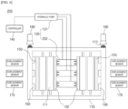
- FIG. 6 is a block diagram illustrating a configuration of a device for performing a pressure test on a battery module according to another embodiment of the present invention.
- a device 200 for performing a pressure test on a battery module may further include a welding fatigue tester 180 for testing a state of a welded portion 112 formed in a module case 110.
- the welding fatigue tester 180 may determine a level of deformation or cracks generated due to fatigue accumulation of the welded portion 112 according to repetition of pressurizing and depressurizing.
- a welding fatigue test may be visually performed and may also be automatically performed by a separate measuring device.
- the welding fatigue tester may include a vision camera for photographing the welded portion.
- the vision camera may be used without limitation as long as it can visually detect the welded portion, such as a charge-coupled device (CCD) camera.
- CCD charge-coupled device
- the vision camera may photograph the welded portion, and the controller may convert the photographed image into visual data through a predetermined computing program included in the controller, represents a level of deformation or cracks occurring in the welded portion from the visual data as a numerical value, and outputs the numerical value to an external device.
- FIG. 7 is a block diagram illustrating a configuration of a device for performing a pressure test on a battery module according to still another embodiment of the present invention.
- FIG. 8 is a graph illustrating a lifetime of the battery cell according to a pressure level.
- a device 300 for performing a pressure test on a battery module may further include a charging/discharging part 190 for charging and discharging a plurality of battery cells 111.
- the charging/discharging part 190 may include a power supply (not shown) connected to electrode leads of the plurality of battery cells 111 to apply a predetermined current or voltage to the battery cells 111.
- the charging/discharging part 190 serves to measure charging/discharging performance of the battery cell according to a pressure condition.
- the charging/discharging performance of the battery cell includes a cycle characteristic according to a pressurized state of the battery cell. Specifically, as shown in FIG. 8 , in a state in which the battery cell is pressurized to a predetermined level, the battery cell is charged and discharged and the charge/discharge performance is measured, and in a state in which the pressure level is changed, the battery cell is charged and discharged and the results (the charge/discharge performance) may be compared. In the case of FIG. 8 , a lifetime characteristic of the battery cell was measured by dividing the pressure level into five levels.
- the lifetime of the battery cell may be measured in various manners.
- the lifetime may be as the number of discharging cycles when a capacity of the battery cell drops to a predetermined level.
- FIG. 8 it means that a magnitude of the pressure force gradually increases from Level 1 to Level 5, and it can be seen that, as the magnitude of the pressure applied to the battery cell increases, the lifetime characteristic of the battery cell is improved, and when the magnitude of the pressure applied to the battery cell exceeds a predetermined level, the lifetime characteristic of the battery cell is reduced. From the above results, it is possible to derive a pressure condition in which the lifetime characteristic of the battery cell is maximized so that specifications and rigidity of a module/pack for deriving an optimal pressure condition can be derived.
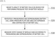
- FIG. 9 is a flowchart illustrating a sequence of the method of performing a pressure test on a battery module according to the present invention.
- the method of performing a pressure test on a battery module includes mounting a plurality of battery cells on the above-described device for performing a pressure test on a battery module (S 10), repeatedly pressurizing and depressurizing the battery cell in the same direction as a swelling direction using a pressure plate and simulating expansion and contraction of the battery cell (S20), and measuring a state change of the module case according to the pressurizing and depressurizing of the battery cell (S30).
- the plurality of battery cells are mounted on the above-described device for performing a pressure test on a battery module.
- the device for performing a pressure test on a battery module according to the present invention includes the module case, the pressure plate, the pressure driver, and the controller.
- the pressure member connected to the hydraulic pump, which is installed outside the module case, through the hydraulic pipe is installed in a middle portion of the module case, and the pressure plate is installed at each of end portions of both sides of the pressure member.
- the pressure sensor and the buffer pad are installed on an inner surface of the module case.
- the battery cell may be mounted between the pressure plate and the buffer pad.
- a process of simulating expansion and contraction of the battery cell is performed by repeatedly pressurizing and depressurizing the battery cell.
- the above process may be controlled by the controller of the above-described device for performing a pressure test on a battery module.
- the pressurizing and depressurizing of the battery cell may be performed while the pressure member repeatedly expands and contracts by the hydraulic pump.
- a swelling behavior of the battery cell is simulated in an actual module while pressurizing and depressurizing the battery cell in a predetermined pattern.
- a plurality of the pressure members and a plurality of the pressure plates may be disposed in the length direction of the battery cell, different pressures may be applied to each portion of the module case so that the behavior simulation may be more accurate.
- the measuring of the state change of the module case may include measuring a displacement of the module case according to pressurizing and depressurizing.
- the measuring of the state change of the module case may include measuring a state change of the welded portion formed in the module case.
- the displacement of the module case according to the pressurizing and depressurizing of the battery cell is measured, and the state change of the welded portion is measured so that it is possible to determine how much the swelling of the battery cell affects the module case and how rigid the module case is.
- the measurement of the state change of the welded portion may be performed by measuring whether cracks occur in the welded portion or whether the welded portion is deformed. A detailed process of measuring the displacement of the module case or measuring the state change of the welded portion formed in the module case is the same as described above.
- the method of performing a pressure test on a battery module which may further include charging and discharging the plurality of battery cells, measuring charging and discharging performance of the battery cell according to a pressure condition, and deriving an optimal pressure level from the charging and discharging performance.
- a pressure condition in which the lifetime characteristic of the battery cell is maximized so that specifications and rigidity of a module/pack for deriving an optimal pressure condition can be derived.
- the pressure plate and the pressure driver which are able to simulate swelling of the battery cell, are installed inside the battery module and artificially pressurize the battery cell, it is possible to simulate that a pressure due to the swelling of the battery cell is applied to the module case in a short time so that it is possible to design a battery module having an optimal condition.
Landscapes
- Chemical & Material Sciences (AREA)
- Chemical Kinetics & Catalysis (AREA)
- Electrochemistry (AREA)
- General Chemical & Material Sciences (AREA)
- Engineering & Computer Science (AREA)
- Manufacturing & Machinery (AREA)
- Physics & Mathematics (AREA)
- General Physics & Mathematics (AREA)
- Battery Mounting, Suspending (AREA)
- Secondary Cells (AREA)
Abstract
Description
- The present invention relates to a device and a method for performing a pressure test on a battery module.
- The present application claims the benefit of priority based on
Korean Patent Application No. 10-2021-0090253 dated July 9, 2021 - Recently, secondary batteries capable of being charged and discharged have been widely used as energy sources for wireless mobile devices. In addition, the secondary batteries are getting attention as energy sources for electric vehicles and hybrid electric vehicles which are proposed as measures to address the air pollution of conventional gasoline and diesel vehicles using fossil fuels. Therefore, types of applications using the secondary batteries are diversifying due to the advantages of the secondary batteries, and it is expected that the secondary batteries are applied to more fields and products in the future than now.
- Secondary batteries may be classified into lithium ion batteries, lithium ion polymer batteries, and lithium polymer batteries according to the composition of an electrode and an electrolyte, and among these batteries, the use of the lithium ion polymer battery, which is less prone to leakage of the electrolyte and easy to manufacture, is increasing. Generally, according to a shape of a battery case, the secondary battery is classified into a cylindrical battery in which an electrode assembly is installed in a cylindrical metal can, a prismatic battery in which an electrode assembly is installed in a prismatic metal can, and a pouch-type battery in which an electrode assembly is installed in a pouch-type case of an aluminum laminated sheet. The electrode assembly installed in the battery case is formed with a structure of a positive electrode, a negative electrode, and a separator interposed between the positive electrode and the negative electrode and is a power generation element capable of being charged and discharged. The electrode assembly is classified into a jelly-roll type electrode assembly in which a separator is interposed between a positive electrode and a negative electrode, which are long sheets coated with an active material, and is wound, and a stack type electrode assembly in which a plurality of positive and negative electrodes, each having a predetermined size, are sequentially stacked with a separator interposed therebetween.
- In particular, an electric vehicle or the like uses high-output electric energy, and thus a plurality of battery modules per vehicle are required. In a state in which a plurality of battery cells are connected in series or in parallel in the battery module, the battery module is mounted in a module case.
- The battery module applies stress to the module case as the battery cells in the battery module repeatedly swells according to repeated charging and discharging. When the stress is continuously applied to the module case, fatigue accumulates in a welded portion of the module case, and thus a phenomenon in which the welded portion is damaged occurs. Therefore, it is necessary to perform a simulation test for fatigue evaluation on the welded portion of the module case.
-
FIG. 1 is a schematic diagram illustrating a structure of a conventional device for performing a pressure test on a battery module. - Referring to
FIG. 1 , aconventional device 1 for performing a pressure test on a battery module uses a method of directly simulating an actual battery module. Specifically, in thedevice 1 for performing a pressure test on a battery module, a plurality ofbattery cells 11 are disposed in parallel in amodule case 10, and abuffer pad 20 may be provided between the outermost battery cell and the module case. In addition, welding is performed on the module case to seal and fix the module case, and thus awelded portion 12 is formed. - In the device for performing a pressure test on a battery module, a charging/discharging cycle of the battery cell is repeated to swell the battery cell so that a degree of fatigue of the welded portion is measured through the stress applied to the module case. However, in this case, since the repeated charging and discharging takes a long time, there is a problem in that the performance of one test takes an excessively long time. In addition, there is a problem in that it is difficult to control the degree of swelling of the battery cell and the resulting pressure.
-
Korean Registered Patent No. 10-2146075 - An object of the present invention is to provide a device and a method for performing a pressure test on a battery module, which simulate a pressure due to swelling of a battery cell applied to the module case in a short time and easily control a pressure.
- In one embodiment of the present invention, there is provided a device for performing a pressure test on a battery module, which includes a module case in which a plurality of battery cells are accommodated, a pressure plate installed in a middle portion of the module case in a width direction and configured to pressure the battery cells toward the module case, a pressure driver configured to apply a pressure to the pressure plate, and a controller configured to control a pressure force and a pressure pattern with respect to the battery cells, wherein the pressure plate simulates expansion and contraction of the battery cells by repeatedly pressurizing and depressurizing the battery cells.
- The pressure plate may pressurize or depressurize the battery cells in the same direction as a swelling direction.
- The pressure driver may include a hydraulic pump and a pressure member connected to the hydraulic pump to pressurize a pressure plate and the battery cells.
- A buffer pad may be disposed between the module case and a battery cell located at an outermost portion among the battery cells accommodated in the module case.
- The device for performing a pressure test on a battery module may further include a pressure sensor configured to measure a pressure applied to an inner surface of the module case facing the battery cells of the module case.
- The device for performing a pressure test on a battery module may further include a displacement sensor located outside the module case and configured to measure a displacement of the module case according to the pressure.
- The pressure plate may be provided as two or more pressure plates disposed in the length direction of the battery cell to pressurize the battery cell with the same pressure or different pressures.
- The pressure member may be provided as two or more pressure members disposed in the length direction of the battery cell to pressurize the battery cells with the same pressure or different pressures.
- The device for performing a pressure test on a battery module may further include a welding fatigue tester configured to test a state of the welded portion formed in the module case.
- The device for performing a pressure test on a battery module may further include a charging/discharging part configured to charge and discharge the plurality of battery cells.
- The charging/discharging part may measure charging/discharging performance of the battery cells according to a pressure condition.
- In addition, according to the present invention, a method of performing a pressure test on a battery module is provided.
- In another embodiment of the present invention, there is provided a method of performing a pressure test on a battery module, which includes mounting a plurality of battery cells on the above-described device for performing a pressure test on a battery module, repeatedly pressurizing and depressurizing the battery cells in the same direction as a swelling direction using a pressure plate and simulating expansion and contraction of the battery cells, and measuring a state change of a module case according to the pressurizing and depressurizing of the battery cells.
- The measuring of the state change of the module case may include measuring a displacement of the module case according to pressurizing and depressurizing.
- The measuring of the state change of the module case may include measuring a state change of a welded portion formed in the module case.
- The method of performing a pressure test on a battery module may further include charging and discharging the plurality of battery cells, measuring charging and discharging performance of the battery cell according to a pressure condition, and deriving an optimal pressure level from the charging and discharging performance.
- According to the present invention, since a pressure plate and a pressure driver, which are able to simulate swelling of the battery cell, are installed inside the battery cell, it is possible to simulate that a pressure due to the swelling of the battery cell is applied to the module case in a short time and to apply a pressure of a desired level.
-
-
FIG. 1 is a schematic diagram illustrating a structure of a conventional device for performing a pressure test on a battery module. -
FIG. 2 is a block diagram illustrating a configuration of the device for performing a pressure test on a battery module according to one embodiment of the present invention. -
FIGS. 3 and4 are schematic diagrams illustrating a structure of the device for performing a pressure test on a battery module according to the present invention. -
FIG. 5 is a graph illustrating an example of a pattern for pressurizing a battery cell. -
FIG. 6 is a block diagram illustrating a configuration of a device for performing a pressure test on a battery module according to another embodiment of the present invention. -
FIG. 7 is a block diagram illustrating a configuration of a device for performing a pressure test on a battery module according to still another embodiment of the present invention. -
FIG. 8 is a graph illustrating a lifetime of the battery cell according to a pressure level. -
FIG. 9 is a flowchart illustrating a sequence of a method of performing a pressure test on a battery module according to the present invention. - Hereinafter, the present invention will be described in detail. Before describing the present invention, terms or words used herein and the appended claims should not be construed to be limited to ordinary or dictionary meanings, and should be construed in accordance with the meaning and concept consistent with the technical spirit of the present invention according to the principle in that inventors can properly define concepts of terms in order to describe their inventions with the best manner.
- In the present application, the terms "comprising," "having," and the like are used to specify the presence of a feature, a number, a step, an operation, a component, an element, or a combination thereof described herein, and they do not preclude the presence or addition of one or more other features, numbers, steps, operations, components, elements, or combinations thereof. In addition, when a portion of a layer, a film, a region, a plate, or the like is referred to as being "on" another portion, this includes not only a case in which the portion is "directly on" another portion but also a case in which still another portion is present between the portion and the other portion. Conversely, when a portion of a layer, a film, a region, a plate, or the like is referred to as being "under" another portion, this includes not only a case in which the portion is "directly under" another portion but also a case in which still another portion is present between the portion and the other portion. In addition, in the present application, being disposed "on" may include the case of being disposed not only on an upper portion but also on a lower portion.
- Meanwhile, in the present application, a "length direction" means a direction in which an electrode lead of a battery cell protrudes.
- Hereinafter, the present invention will be described in detail.
-
FIG. 2 is a block diagram illustrating a configuration of the device for performing a pressure test on a battery module according to one embodiment of the present invention, andFIGS. 3 and4 are schematic diagrams illustrating a structure of the device for performing a pressure test on a battery module according to the present invention. - Referring to
FIGS. 2 to 4 , adevice 100 for performing a pressure test on a battery module according to the present invention includes amodule case 110 in which a plurality ofbattery cells 111 are accommodated, apressure plate 120 installed in a middle portion of themodule case 110 in a width direction and configured to pressure thebattery cell 111 toward themodule case 110, apressure driver 130 configured to apply a pressure to thepressure plate 120, and acontroller 140 configured to control a pressure force and a pressure pattern with respect to thebattery cell 111, and thepressure plate 120 simulates expansion and contraction of the battery cell by repeatedly pressurizing and depressurizing thebattery cell 111. - According to the present invention, since the pressure plate and the pressure driver, which are able to simulate swelling of the battery cell, are installed inside the battery module and artificially pressurize the battery cell, it is possible to simulate that a pressure due to the swelling of the battery cell is applied to the module case in a short time and to apply a pressure of a desired level.
- Hereinafter, each component of the device for performing a pressure test on a battery module will be described in detail.
- A
device 100 for performing a pressure test on a battery module according to the present invention simulates a general battery module and has a structure in which thebattery cell 111 is accommodated in themodule case 110. - The
module case 110 may employ the same module case as that used for a general battery module, and a metal material having excellent rigidity, such as iron or stainless steel, may be used, but a type of the material is not limited thereto. - The
battery cell 111 may also employ the same battery cell as that used for a general battery module, and there is no particular limitation on its shape, but in the present invention, a pouch-type battery cell to which a surface pressure can be applied may be used. The pouch-type battery cell has a structure in which an electrode assembly is accommodated in a pouch-type battery case, electrode leads are drawn out from one end portion or both end portions of the battery case, and a sealing part is formed on an outer periphery of the battery case. A specific content related to other battery cells is known to those skilled in the art, and thus a detailed description thereof will be omitted herein. - As described above, a plurality of battery cells are mounted in the battery module, and as the battery cells are repeatedly charged and discharged, the battery cells swell repeatedly, and due to stress by the swelling, physical damage such as cracks may occur in the welded portion of the module case.
- According to the present invention, in order to simulate the swelling of the battery cell, a pressure part capable of pressurize the battery cell in the module case is provided.
- Specifically, according to the present invention, a
pressure plate 120 for pressurizing the battery cell and apressure driver 130 for applying a pressure to thepressure plate 120 are provided as the pressure part. - The
pressure plate 120 simulates expansion and contraction of the battery cell by repeatedly pressurizing and depressurizing thebattery cell 111 and pressurizes or depressurizes thebattery cell 111 in themodule case 110 in the same direction as a swelling direction. Accordingly, thepressure plate 120 pressurizes or depressurizes thebattery cell 111 in a direction perpendicular to a wide surface of the battery case. - The
pressure plate 120 is located in a middle portion of themodule case 110. As described below, in order to cover the pressure member located in the middle portion, a pair ofpressure plate 120 is located on both sides of the pressure member in an internal space of themodule case 110. Accordingly, thepressure plate 120 pressurizes the battery cells in both directions of themodule case 110. - The
pressure plate 120 may employ a material without limitation as long as it has a rigid enough not to be easily deformed or damaged even when the battery cell is pressurized and has heat resistance enough not to be damaged due to heat generated from the battery cell. - The
pressure driver 130 applies a pressure to thepressure plate 120. - Referring to
FIG. 2 , thepressure driver 130 may include ahydraulic pump 131 and apressure member 132 connected to thehydraulic pump 131 and configured to pressurize thepressure plate 120 and the battery cell. Thehydraulic pump 131 and thepressure member 132 are connected by a hydraulic pipe, and when thehydraulic pump 131 pushes a fluid in the hydraulic pipe, thepressure member 132 expands to push thepressure plate 120 to both sides of themodule case 110. Thepressure member 132 may be, for example, a hydraulic cylinder having a space in which a fluid for applying a hydraulic pressure may be introduced therein and repeatedly expanding and contracting according to an inflow and an outflow of the fluid, but a type of thepressure member 132 is not limited thereto. As described below, two ormore pressure members 132 are disposed in a length direction of thebattery cell 111, and eachpressure member 132 may be connected to the hydraulic pump through a separate hydraulic pipe to independently pressurize the pressure plate. That is, according to the present invention, since the swelling of the battery cell is simulated by directly applying a pressure to the battery cell through the pressure plate and the pressure driver without directly swelling the battery cell, there is an advantage of reducing a measurement time compared to when the battery cell directly swells and controlling a pressure pattern as desired. - As described above, when the
pressure plate 120 applies a pressure in the swelling direction of the battery cell by thepressure driver 130, thebattery cell 111 transfers the pressure force to themodule case 110, and thus themodule case 110 receives the pressure to be deformed. In this case, pressure forces superimposed by the battery cells may act on an outermost battery cell, and thus themodule case 110 and the outermost battery cell may be damaged. In order to prevent the above problem, abuffer pad 150 formed of an absorbing material for protecting thebattery cell 111 and themodule case 110 may be disposed between themodule case 110 and the outermost battery cell among the battery cells accommodated in themodule case 110. - In addition, as described above, when the
module case 110 is deformed due to the pressure applied thereto, thedevice 100 for performing a pressure test on a battery module according to the present invention includes apressure sensor 160 and adisplacement sensor 170 for measuring an amount and deformation degree of the pressure. - The
pressure sensor 160 is located on an inner surface of themodule case 110 facing thebattery cell 111 and measures a pressure transferred from the outermost battery cell or thebuffer pad 150. Specifically, thepressure sensor 160 is a load cell and converts and outputs a pressure applied to the load cell through a strain gauge into an electrical signal, thereby displaying the pressure. A type of the pressure sensor is not particularly limited as long as it can output a numerical value of a pressure, and for example, various types of load cells such as a beam load cell and a columnar load cell may be used. - In addition, the
displacement sensor 170 is located outside themodule case 110 to measure a displacement of themodule case 110 according to the pressure. A type of thedisplacement sensor 170 is not particularly limited as long as it can measure movement of the module case according to the pressure, and for example, a linear variable differential transducer (LVDT) may be used. The LVDT is to measure a linear position according to a motion of an object, which is performed by a measurement target along a single axis in one direction and may measure a direction of the motion and a distance in which the measurement target moves. - Meanwhile, referring to
FIGS. 3 and4 along withFIG. 2 , according to the present invention, in order to simulate accurate swelling, different amplitudes of pressures may be applied to portions of the module case. - In a specific example, in the present invention, two or
more pressure plates 120 may be disposed in the length direction of the battery cell to pressurize thebattery cell 111 with the same pressure or different pressures. Similarly, two ormore pressure members 132 are disposed in the length direction of the battery cell to pressurize thebattery cell 111 with the same pressure or different pressures. - Accordingly, it is possible to accurately simulate the swelling of the battery cell in the actual battery module. In a typical pouch-type battery cell, swelling may occur due to gas generation resulting from a side reaction in which an electrolyte in the battery cell is decomposed. When the gas is excessively generated, a central portion of the battery cell is more vulnerable to deformation due to a pressure than an edge of the battery cell so that the central portion of the battery cell may swell more than both edges. In this case, a portion of the module case facing the central portion of the battery cell receives higher pressure than portions facing both edges. As described above, according to the present invention, when the swelling occurs, a greater pressure is applied to the portion (for example, the central portion of the battery cell) of the module case which receives a higher pressure than the portion (for example, the edge of the battery cell) of the module case which receives a lower pressure so that a behavior of the battery cell can be more accurately simulated.
- Referring to
FIGS. 3 and4 , thepressure member 132 in the form of a hydraulic cylinder may be disposed as threepressure members pressure members pressure plate 120 may also be formed as a total of sixpressure plates pressure member 132 and thepressure plate 120, thepressure sensor 160 are formed as a plurality ofpressure sensors FIG. 2 , thedisplacement sensor 170 is also disposed as a plurality ofdisplacement sensors 170 in the length direction of the battery cell so that a displacement of each portion of themodule case 110 may be measured. - As described above, pressurizing and depressurizing the
battery cell 111 may be controlled by thecontroller 140. Thecontroller 140 may simulate a swelling pattern of an actual battery cell to control a pressure force and a pressure pattern of the battery cell. For example, as shown inFIG. 5 , thecontroller 140 may control operations of the pressure plate and the pressure driver to pressurize the battery cell by varying a pressure over time in the form of a sine wave. -
FIG. 6 is a block diagram illustrating a configuration of a device for performing a pressure test on a battery module according to another embodiment of the present invention. - Referring to
FIG. 6 , adevice 200 for performing a pressure test on a battery module may further include awelding fatigue tester 180 for testing a state of a weldedportion 112 formed in amodule case 110. Specifically, thewelding fatigue tester 180 may determine a level of deformation or cracks generated due to fatigue accumulation of the weldedportion 112 according to repetition of pressurizing and depressurizing. - In the present invention, a welding fatigue test may be visually performed and may also be automatically performed by a separate measuring device. For example, the welding fatigue tester may include a vision camera for photographing the welded portion. The vision camera may be used without limitation as long as it can visually detect the welded portion, such as a charge-coupled device (CCD) camera. The vision camera may photograph the welded portion, and the controller may convert the photographed image into visual data through a predetermined computing program included in the controller, represents a level of deformation or cracks occurring in the welded portion from the visual data as a numerical value, and outputs the numerical value to an external device.
-
FIG. 7 is a block diagram illustrating a configuration of a device for performing a pressure test on a battery module according to still another embodiment of the present invention.FIG. 8 is a graph illustrating a lifetime of the battery cell according to a pressure level. - Referring to
FIG. 7 , adevice 300 for performing a pressure test on a battery module may further include a charging/dischargingpart 190 for charging and discharging a plurality ofbattery cells 111. The charging/dischargingpart 190 may include a power supply (not shown) connected to electrode leads of the plurality ofbattery cells 111 to apply a predetermined current or voltage to thebattery cells 111. - Specifically, the charging/discharging
part 190 serves to measure charging/discharging performance of the battery cell according to a pressure condition. Here, the charging/discharging performance of the battery cell includes a cycle characteristic according to a pressurized state of the battery cell. Specifically, as shown inFIG. 8 , in a state in which the battery cell is pressurized to a predetermined level, the battery cell is charged and discharged and the charge/discharge performance is measured, and in a state in which the pressure level is changed, the battery cell is charged and discharged and the results (the charge/discharge performance) may be compared. In the case ofFIG. 8 , a lifetime characteristic of the battery cell was measured by dividing the pressure level into five levels. Here, the lifetime of the battery cell may be measured in various manners. For example, the lifetime may be as the number of discharging cycles when a capacity of the battery cell drops to a predetermined level. InFIG. 8 , it means that a magnitude of the pressure force gradually increases fromLevel 1 toLevel 5, and it can be seen that, as the magnitude of the pressure applied to the battery cell increases, the lifetime characteristic of the battery cell is improved, and when the magnitude of the pressure applied to the battery cell exceeds a predetermined level, the lifetime characteristic of the battery cell is reduced. From the above results, it is possible to derive a pressure condition in which the lifetime characteristic of the battery cell is maximized so that specifications and rigidity of a module/pack for deriving an optimal pressure condition can be derived. - In addition, according to the present invention, a method of performing a pressure test on a battery module.
-
FIG. 9 is a flowchart illustrating a sequence of the method of performing a pressure test on a battery module according to the present invention. - Referring to
FIG. 9 , the method of performing a pressure test on a battery module according to the present invention includes mounting a plurality of battery cells on the above-described device for performing a pressure test on a battery module (S 10), repeatedly pressurizing and depressurizing the battery cell in the same direction as a swelling direction using a pressure plate and simulating expansion and contraction of the battery cell (S20), and measuring a state change of the module case according to the pressurizing and depressurizing of the battery cell (S30). - Hereinafter, each process of the method of performing a pressure test on a battery module according to the present invention will be described.
- First, the plurality of battery cells are mounted on the above-described device for performing a pressure test on a battery module. As described above, the device for performing a pressure test on a battery module according to the present invention includes the module case, the pressure plate, the pressure driver, and the controller. Specifically, the pressure member connected to the hydraulic pump, which is installed outside the module case, through the hydraulic pipe is installed in a middle portion of the module case, and the pressure plate is installed at each of end portions of both sides of the pressure member. In addition, the pressure sensor and the buffer pad are installed on an inner surface of the module case. The battery cell may be mounted between the pressure plate and the buffer pad.
- When the battery cell is mounted in the module case, a process of simulating expansion and contraction of the battery cell is performed by repeatedly pressurizing and depressurizing the battery cell. The above process may be controlled by the controller of the above-described device for performing a pressure test on a battery module. The pressurizing and depressurizing of the battery cell may be performed while the pressure member repeatedly expands and contracts by the hydraulic pump. In this case, as shown in
FIG. 5 , a swelling behavior of the battery cell is simulated in an actual module while pressurizing and depressurizing the battery cell in a predetermined pattern. In this case, since a plurality of the pressure members and a plurality of the pressure plates may be disposed in the length direction of the battery cell, different pressures may be applied to each portion of the module case so that the behavior simulation may be more accurate. - As the pressurizing and depressurizing of the battery cell are repeated, stress is concentrated in and released from the module case, and the deformation of the module case is repeated. Accordingly, fatigue may accumulate in the welded portion formed in the module case, and thus deformation or cracking may occur.
- In the present invention, the measuring of the state change of the module case may include measuring a displacement of the module case according to pressurizing and depressurizing. In addition, the measuring of the state change of the module case may include measuring a state change of the welded portion formed in the module case. According to the present invention, the displacement of the module case according to the pressurizing and depressurizing of the battery cell is measured, and the state change of the welded portion is measured so that it is possible to determine how much the swelling of the battery cell affects the module case and how rigid the module case is. Here, the measurement of the state change of the welded portion may be performed by measuring whether cracks occur in the welded portion or whether the welded portion is deformed. A detailed process of measuring the displacement of the module case or measuring the state change of the welded portion formed in the module case is the same as described above.
- In addition, the method of performing a pressure test on a battery module, which may further include charging and discharging the plurality of battery cells, measuring charging and discharging performance of the battery cell according to a pressure condition, and deriving an optimal pressure level from the charging and discharging performance. Specific details related to the above description are the same as described above, and according to the present invention, it is possible to derive a pressure condition in which the lifetime characteristic of the battery cell is maximized so that specifications and rigidity of a module/pack for deriving an optimal pressure condition can be derived.
- As described above, according to the present invention, since the pressure plate and the pressure driver, which are able to simulate swelling of the battery cell, are installed inside the battery module and artificially pressurize the battery cell, it is possible to simulate that a pressure due to the swelling of the battery cell is applied to the module case in a short time so that it is possible to design a battery module having an optimal condition.
- Although the embodiments have been described with reference to a number of illustrative embodiments of the technical spirit of the present invention, it should be understood that numerous other modifications and embodiments can be devised by those skilled in the art that will fall within the spirit and scope of the principles of the present invention. Therefore, the drawings disclosed herein are not to be taken in a sense of limiting the technical concept of the present invention but for explanation thereof, and the range of the technical concept is not limited to these drawings. The scope of the present invention should be construed by the appended claims, along with the full range of equivalents to which such claims are entitled.
- Meanwhile, in the present specification, terms indicating upward, downward, leftward, rightward, forward, and rearward directions are used, and these terms are merely for convenience of description, and it is obvious that these terms may be changed according to a location of an object or an observer.
-
- 1 and 100: devices for performing pressure test on battery module
- 10 and 110: module cases
- 11 and 111: battery cells
- 12 and 112: welded portions
- 20 and 150: buffer pads
- 120: pressure plate
- 130: pressure driver
- 131: hydraulic pump
- 132: pressure member
- 140: controller
- 160: pressure sensor
- 170: displacement sensor
- 180: welding fatigue tester
- 190: charging/discharging part
Claims (15)
- A device for performing a pressure test on a battery module, the device comprising:a module case in which a plurality of battery cells are accommodated;a pressure plate installed in a middle portion of the module case in a width direction and configured to pressure the plurality of battery cells toward the module case;a pressure driver configured to apply a pressure to the pressure plate; anda controller configured to control a pressure force and a pressure pattern with respect to the plurality of battery cells,wherein the pressure plate is configured to simulate expansion and contraction of the plurality of battery cells by repeatedly pressurizing and depressurizing the plurality of battery cells.
- The device of claim 1, wherein the pressure plate is configured to pressurize or depressurize the plurality of battery cells in a same direction as a swelling direction.
- The device of claim 1, wherein the pressure driver includes a hydraulic pump and a pressure member connected to the hydraulic pump to pressurize the pressure plate and the plurality of battery cells.
- The device of claim 1, wherein a buffer pad is disposed between the module case and a battery cell located at an outermost portion among the plurality of battery cells accommodated in the module case.
- The device of claim 1, further comprising a pressure sensor disposed at an inner surface of the module case facing at least one of the plurality of battery cells and configured to measure a pressure applied to the module case.
- The device of claim 1, wherein a displacement sensor located outside the module case and configured to measure a displacement of the module case according to the pressure.
- The device of claim 1, wherein the pressure plate is provided as two or more pressure plates disposed in a length direction of the plurality of battery cells to pressurize the plurality of battery cells with a same pressure or different pressures.
- The device of claim 3, wherein the pressure member is provided as two or more pressure members disposed in a length direction of the plurality of battery cells to pressurize the plurality of battery cells with a same pressure or different pressures.
- The device of claim 1, further comprising a welding fatigue tester configured to test a state of a welded portion formed in the module case.
- The device of claim 1, further comprising a charging/discharging part configured to charge and discharge the plurality of battery cells.
- The device of claim 10, wherein the charging/discharging part is configured to measure charging/discharging performance of the plurality of battery cells according to a pressure condition.
- A method of performing a pressure test on a battery module, the method comprising:mounting the plurality of battery cells on the device for performing the pressure test on the battery module according to claim 1;repeatedly pressurizing and depressurizing the plurality of battery cells in a same direction as a swelling direction using the pressure plate and simulating expansion and contraction of the plurality of battery cells; andmeasuring a state change of the module case according to the pressurizing and depressurizing of the plurality of battery cells.
- The method of claim 12, wherein the measuring of the state change of the module case includes measuring a displacement of the module case according to the pressurizing and depressurizing.
- The method of claim 12, wherein the measuring of the state change of the module case includes measuring a state change of a welded portion formed in the module case.
- The method of claim 12, further comprising:charging and discharging the plurality of battery cells;measuring charging and discharging performance of the plurality of battery cells according to a pressure condition; andderiving an optimal pressure level from the charging and discharging performance.
Applications Claiming Priority (2)
| Application Number | Priority Date | Filing Date | Title |
|---|---|---|---|
| KR1020210090253A KR102939482B1 (en) | 2021-07-09 | 2021-07-09 | Apparatus and method for pressure test of battery module |
| PCT/KR2022/009713 WO2023282601A1 (en) | 2021-07-09 | 2022-07-06 | Battery module pressing test device and method |
Publications (3)
| Publication Number | Publication Date |
|---|---|
| EP4246656A1 true EP4246656A1 (en) | 2023-09-20 |
| EP4246656A4 EP4246656A4 (en) | 2025-03-19 |
| EP4246656B1 EP4246656B1 (en) | 2026-03-18 |
Family
ID=84800723
Family Applications (1)
| Application Number | Title | Priority Date | Filing Date |
|---|---|---|---|
| EP22837953.3A Active EP4246656B1 (en) | 2021-07-09 | 2022-07-06 | Battery module pressing test device and method |
Country Status (6)
| Country | Link |
|---|---|
| US (1) | US20240055675A1 (en) |
| EP (1) | EP4246656B1 (en) |
| JP (1) | JP7540859B2 (en) |
| KR (1) | KR102939482B1 (en) |
| CN (1) | CN116635690A (en) |
| WO (1) | WO2023282601A1 (en) |
Cited By (1)
| Publication number | Priority date | Publication date | Assignee | Title |
|---|---|---|---|---|
| DE102024109260A1 (en) * | 2024-04-03 | 2025-10-09 | Iav Gmbh Ingenieurgesellschaft Auto Und Verkehr | Cell simulator |
Families Citing this family (4)
| Publication number | Priority date | Publication date | Assignee | Title |
|---|---|---|---|---|
| CN115993222B (en) * | 2023-02-14 | 2026-04-17 | 蜂巢能源科技股份有限公司 | Cell Expansion Stiffness Test Method |
| KR20250023632A (en) * | 2023-08-10 | 2025-02-18 | 주식회사 엘지에너지솔루션 | Device for pouch forming and pouch forming method using the same |
| KR20250078205A (en) * | 2023-11-24 | 2025-06-02 | 삼성에스디아이 주식회사 | Test apparatus and method for all-solid rechargeable battery |
| CN119936698A (en) * | 2025-01-16 | 2025-05-06 | 武汉船用电力推进装置研究所(中国船舶集团有限公司第七一二研究所) | Battery module pressure testing device and testing method |
Family Cites Families (17)
| Publication number | Priority date | Publication date | Assignee | Title |
|---|---|---|---|---|
| US8162020B2 (en) * | 2005-08-24 | 2012-04-24 | Battery Patent Trust | Infra-red thermal imaging of laser welded battery module enclosure components |
| KR101136786B1 (en) * | 2007-12-07 | 2012-04-19 | 가부시키가이샤 엔티티 도코모 | Battery testing device and battery testing method |
| US9306252B2 (en) * | 2012-06-11 | 2016-04-05 | Nucleus Scientific, Inc. | Dynamic pressure control in a battery assembly |
| KR101841803B1 (en) * | 2014-09-17 | 2018-03-23 | 주식회사 엘지화학 | Battery module of improved safety by monitoring of pressure state of battery cell and battery pack containing the same |
| KR102146075B1 (en) | 2017-04-13 | 2020-08-19 | 주식회사 엘지화학 | Apparatus and method for testing end plates |
| KR102357026B1 (en) * | 2017-06-14 | 2022-01-28 | 에스케이온 주식회사 | Test Device for Battery Cell |
| KR102290736B1 (en) * | 2018-11-21 | 2021-08-18 | 주식회사 엘지에너지솔루션 | Pressure short testing device for detecting a low voltage battery cell |
| KR102698904B1 (en) * | 2018-09-13 | 2024-08-23 | 주식회사 엘지에너지솔루션 | Battery module with improved insulation structure and Battery Pack comprising the battry module |
| EP3919313A1 (en) * | 2018-09-20 | 2021-12-08 | LG Hausys, Ltd. | Lower protecting plate of battery module for electric car |
| KR102619196B1 (en) * | 2018-10-17 | 2023-12-27 | 주식회사 엘지에너지솔루션 | Apparatus for detecting a low voltage pouch type secondary battery cell |
| KR102408132B1 (en) * | 2018-11-21 | 2022-06-14 | 주식회사 엘지에너지솔루션 | Method for testing pressure short defect by jig pressing |
| WO2020120050A1 (en) | 2018-12-14 | 2020-06-18 | Asml Netherlands B.V. | Apparatus and method for grouping image patterns to determine wafer behavior in a patterning process |
| KR102825806B1 (en) * | 2019-02-08 | 2025-06-25 | 에스케이온 주식회사 | Battery Module |
| KR102147096B1 (en) * | 2019-05-08 | 2020-08-25 | 주식회사 에스아이티 | Folding case for battery pack |
| CN210607516U (en) * | 2019-08-07 | 2020-05-22 | 欣旺达电动汽车电池有限公司 | Battery module with pressure monitoring function |
| KR102770968B1 (en) * | 2019-11-07 | 2025-02-19 | 주식회사 엘지에너지솔루션 | Jig for measuring cell swelling pressure |
| KR102815957B1 (en) * | 2020-11-10 | 2025-05-30 | 주식회사 엘지에너지솔루션 | Fatigue damage verification device for the welding part of the housing of the battery module |
-
2021
- 2021-07-09 KR KR1020210090253A patent/KR102939482B1/en active Active
-
2022
- 2022-07-06 EP EP22837953.3A patent/EP4246656B1/en active Active
- 2022-07-06 JP JP2023537370A patent/JP7540859B2/en active Active
- 2022-07-06 WO PCT/KR2022/009713 patent/WO2023282601A1/en not_active Ceased
- 2022-07-06 CN CN202280008419.4A patent/CN116635690A/en active Pending
- 2022-07-06 US US18/268,200 patent/US20240055675A1/en active Pending
Cited By (1)
| Publication number | Priority date | Publication date | Assignee | Title |
|---|---|---|---|---|
| DE102024109260A1 (en) * | 2024-04-03 | 2025-10-09 | Iav Gmbh Ingenieurgesellschaft Auto Und Verkehr | Cell simulator |
Also Published As
| Publication number | Publication date |
|---|---|
| US20240055675A1 (en) | 2024-02-15 |
| KR102939482B1 (en) | 2026-03-17 |
| EP4246656A4 (en) | 2025-03-19 |
| WO2023282601A1 (en) | 2023-01-12 |
| KR20230009620A (en) | 2023-01-17 |
| JP7540859B2 (en) | 2024-08-27 |
| EP4246656B1 (en) | 2026-03-18 |
| CN116635690A (en) | 2023-08-22 |
| JP2024500139A (en) | 2024-01-04 |
Similar Documents
| Publication | Publication Date | Title |
|---|---|---|
| EP4246656B1 (en) | Battery module pressing test device and method | |
| JP5444762B2 (en) | Pressure measuring device and thickness measuring device | |
| CN114946067A (en) | Battery cell holder comprising a membrane pressure sensor and method for measuring the swelling of a battery cell | |
| KR102623517B1 (en) | Apparatus and method for measuring mechanical property related to deformation of object | |
| KR102070684B1 (en) | Secondary battery evaluation apparatus | |
| KR102872091B1 (en) | Cell jig for detecting swelling of battery cell and method for measuring swelling of the battery cell using the same | |
| CN109565085B (en) | Apparatus for predicting deformation of battery module | |
| CN104303358A (en) | Device for determining state parameters of a battery for converting chemical energy into electrical energy, battery, battery module and method for determining state parameters of a battery | |
| CN111684646A (en) | Explosion pressure prediction system for medium and large monomer modules and method for predicting explosion pressure of medium and large monomer modules | |
| CN111656207B (en) | Method for determining stage of generation acceleration of internal gas in secondary battery | |
| CN114787604A (en) | Apparatus for measuring cell pressure | |
| KR102900744B1 (en) | Cell jig for measuring swelling of battery cell including ultrasonic sensor and method for measuring swelling of the battery cell using the same | |
| CN109103485A (en) | The manufacturing method and manufacturing device of fuel cell pack | |
| EP3995844A1 (en) | Battery defect screening device and method | |
| EP4087011B1 (en) | Battery cell jig comprising spacer laminate, apparatus comprising same for measuring volume of battery cell, and method for measuring volume of battery cell using same | |
| KR20170019880A (en) | Charging-Discharging Apparatus Capable of Measuring Thickness of Battery Cell | |
| EP4087010B1 (en) | Apparatus for measuring volume of a battery cell comprising a battery cell jig including a spacer and method for measuring volume of battery cell using same | |
| JP7666143B2 (en) | Battery pack inspection method | |
| EP4492035A1 (en) | Accelerated fatigue evaluation device for welded portion of vehicle battery module frame | |
| EP4280370A1 (en) | Method and apparatus for transmitting and receiving signal in communication system | |
| EP4592660A1 (en) | Leak inspection apparatus and method for secondary battery cell | |
| KR20230103981A (en) | A battery module and battery pack capable of early detection of gas venting and a method for early detection of gas venting | |
| KR102953661B1 (en) | System for measuring internal pressure of battery cell and method for measuring internal pressure of battery cell using the same | |
| US20230087294A1 (en) | Assembled battery testing method | |
| WO2025228956A1 (en) | Method and system for testing battery cells |
Legal Events
| Date | Code | Title | Description |
|---|---|---|---|
| STAA | Information on the status of an ep patent application or granted ep patent |
Free format text: STATUS: THE INTERNATIONAL PUBLICATION HAS BEEN MADE |
|
| PUAI | Public reference made under article 153(3) epc to a published international application that has entered the european phase |
Free format text: ORIGINAL CODE: 0009012 |
|
| STAA | Information on the status of an ep patent application or granted ep patent |
Free format text: STATUS: REQUEST FOR EXAMINATION WAS MADE |
|
| 17P | Request for examination filed |
Effective date: 20230615 |
|
| AK | Designated contracting states |
Kind code of ref document: A1 Designated state(s): AL AT BE BG CH CY CZ DE DK EE ES FI FR GB GR HR HU IE IS IT LI LT LU LV MC MK MT NL NO PL PT RO RS SE SI SK SM TR |
|
| DAV | Request for validation of the european patent (deleted) | ||
| DAX | Request for extension of the european patent (deleted) | ||
| A4 | Supplementary search report drawn up and despatched |
Effective date: 20250217 |
|
| RIC1 | Information provided on ipc code assigned before grant |
Ipc: G01B 5/30 20060101ALI20250211BHEP Ipc: H01M 10/04 20060101ALI20250211BHEP Ipc: H01M 10/48 20060101ALI20250211BHEP Ipc: H01M 10/44 20060101ALI20250211BHEP Ipc: H01M 10/42 20060101AFI20250211BHEP |
|
| GRAP | Despatch of communication of intention to grant a patent |
Free format text: ORIGINAL CODE: EPIDOSNIGR1 |
|
| STAA | Information on the status of an ep patent application or granted ep patent |
Free format text: STATUS: GRANT OF PATENT IS INTENDED |
|
| RIC1 | Information provided on ipc code assigned before grant |
Ipc: H01M 10/42 20060101AFI20250924BHEP Ipc: H01M 10/44 20060101ALI20250924BHEP Ipc: H01M 10/48 20060101ALI20250924BHEP Ipc: H01M 10/04 20060101ALI20250924BHEP Ipc: G01B 5/30 20060101ALI20250924BHEP |
|
| INTG | Intention to grant announced |
Effective date: 20251010 |
|
| GRAS | Grant fee paid |
Free format text: ORIGINAL CODE: EPIDOSNIGR3 |
|
| GRAA | (expected) grant |
Free format text: ORIGINAL CODE: 0009210 |
|
| STAA | Information on the status of an ep patent application or granted ep patent |
Free format text: STATUS: THE PATENT HAS BEEN GRANTED |
|
| AK | Designated contracting states |
Kind code of ref document: B1 Designated state(s): AL AT BE BG CH CY CZ DE DK EE ES FI FR GB GR HR HU IE IS IT LI LT LU LV MC MK MT NL NO PL PT RO RS SE SI SK SM TR |
|
| REG | Reference to a national code |
Ref country code: CH Ref legal event code: F10 Free format text: ST27 STATUS EVENT CODE: U-0-0-F10-F00 (AS PROVIDED BY THE NATIONAL OFFICE) Effective date: 20260318 Ref country code: GB Ref legal event code: FG4D |
|
| P01 | Opt-out of the competence of the unified patent court (upc) registered |
Free format text: CASE NUMBER: UPC_APP_0006123_4246656/2026 Effective date: 20260219 |
|
| REG | Reference to a national code |
Ref country code: DE Ref legal event code: R096 Ref document number: 602022032699 Country of ref document: DE |
|
| REG | Reference to a national code |
Ref country code: IE Ref legal event code: FG4D |