EP4246472A1 - Coin handling apparatus and coin handling method - Google Patents
Coin handling apparatus and coin handling method Download PDFInfo
- Publication number
- EP4246472A1 EP4246472A1 EP23161777.0A EP23161777A EP4246472A1 EP 4246472 A1 EP4246472 A1 EP 4246472A1 EP 23161777 A EP23161777 A EP 23161777A EP 4246472 A1 EP4246472 A1 EP 4246472A1
- Authority
- EP
- European Patent Office
- Prior art keywords
- cassette
- coin
- handling apparatus
- coins
- confirmation operation
- Prior art date
- Legal status (The legal status is an assumption and is not a legal conclusion. Google has not performed a legal analysis and makes no representation as to the accuracy of the status listed.)
- Granted
Links
Images


Classifications
-
- G—PHYSICS
- G07—CHECKING-DEVICES
- G07D—HANDLING OF COINS OR VALUABLE PAPERS, e.g. TESTING, SORTING BY DENOMINATIONS, COUNTING, DISPENSING, CHANGING OR DEPOSITING
- G07D9/00—Counting coins; Handling of coins not provided for in the other groups of this subclass
- G07D9/002—Coin holding devices
-
- G—PHYSICS
- G07—CHECKING-DEVICES
- G07D—HANDLING OF COINS OR VALUABLE PAPERS, e.g. TESTING, SORTING BY DENOMINATIONS, COUNTING, DISPENSING, CHANGING OR DEPOSITING
- G07D11/00—Devices accepting coins; Devices accepting, dispensing, sorting or counting valuable papers
-
- G—PHYSICS
- G07—CHECKING-DEVICES
- G07F—COIN-FREED OR LIKE APPARATUS
- G07F11/00—Coin-freed apparatus for dispensing, or the like, discrete articles
- G07F11/46—Coin-freed apparatus for dispensing, or the like, discrete articles from movable storage containers or supports
Definitions
- the present disclosure relates to a coin handling apparatus and a coin handling method.
- Patent Literature As disclosed in Patent Literature (hereinafter, referred to as PTL) 1, for example, a coin handling apparatus for handling coins is known.
- An object of the present disclosure is to provide a money handling apparatus and a money handling method both capable of completing the transferring of coins to a cassette in a short time.
- a coin handling apparatus comprises: a cassette attachment unit where a cassette is configured to be attached; a coin supply unit configured to supply a coin to the cassette; and a control unit that causes the cassette attached to the cassette attachment unit to perform a first confirmation operation when the cassette does not satisfy a predetermined condition, the first confirmation operation being an operation for confirming that a coin remains in the cassette, and operates the coin supply unit to supply a coin to the cassette attached to the cassette attachment unit without causing the cassette to perform the first confirmation operation when the cassette satisfies the predetermined condition.
- the first confirmation operation may be an operation of confirming whether or not a coin remain in the cassette.
- the cassette may comprise a conveyor for transporting coins in the cassette and a sensor for detecting a coin in the cassette.
- the first confirmation operation may be the operation of a conveyor for transporting a coin to a detection area of the sensor.
- the control unit may cause the cassette to perform a second confirmation operation different from the first confirmation operation, the second confirmation operation being for confirming that a coin remains in the cassette.
- the second confirmation operation may be an operation of confirming whether or not a coin remains in the cassette.
- the second confirmation operation may be a combination of an operation of the conveyor for transporting a coin in a first direction toward the detection area of the sensor and an operation of the conveyor for transporting a coin in a second direction different from the first direction.
- the control unit may be configured to be able to acquire the inventory amount in the cassette.
- the control unit may generate a signal to notify that the coin has been detected.
- the control unit may be configured to be able to acquire the inventory amount from a memory comprised in the cassette.
- the predetermined condition may be a condition such that the cassette is attached to a cassette attachment unit within a predetermined time after the cassette was last emptied (i.e. the last emptying of the cassette).
- the predetermined condition may be a condition such that the cassette is attached to the cassette attachment unit of the coin handling apparatus that has last emptied the cassette.
- the predetermined condition may be a condition such that both of these conditions are satisfied.
- a coin handling method is performed by a coin handling apparatus configured to supply a coin to a cassette, and the coin handling method comprises: determining whether or not the cassette attached to a cassette attachment unit satisfies a predetermined condition; causing the cassette to perform a first confirmation operation for confirming that a coin remains in the cassette when the cassette does not satisfy the predetermined condition; and supplying a coin to the cassette without causing the cassette to perform the first confirmation operation when the cassette satisfies the predetermined condition.
- the present disclosure can provide a money handling apparatus and a money handling method both capable of completing the transferring of coins to a cassette in a short time.
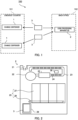
- FIG. 1 is a schematic diagram illustrating a coin handling system 100.
- the coin handling system 100 comprises change dispensers 1, a coin handling apparatus 2, and cassettes 3.
- the change dispenser 1 is disposed at a checkout counter 101.
- a plurality of change dispensers 1 may be disposed at the checkout counter 101.
- the change dispenser 1 is connected to a POS terminal, a kiosk terminal, or the like, and dispenses banknotes and coins as change necessary for settlement of the purchase price of merchandise.
- the coin handling apparatus 2 is disposed in a back office 102.
- the coin handling apparatus 2 stores coins collected from the change dispenser 1 and dispenses a change fund required by the change dispenser 1.
- the cassette 3 is a container used for transferring coins between the change dispensers 1 and the coin handling apparatus 2.
- the number of cassettes 3 in the coin handling system 100 may be one, or two or more.
- a plurality of change dispensers 1 may share single cassette 3.
- the cassette 3 is attached to the change dispenser 1 and the coins in the change dispenser 1 are transferred to the cassette 3.
- the cassette 3 with the coins stored therein is then attached to the coin handling apparatus 2, and the coins are transferred from the cassette 3 to the coin handling apparatus 2.
- the cassette 3 is emptied.
- the cassette 3 is attached to the coin handling apparatus 2 and coins in the coin handling apparatus 2 are transferred to the cassette 3.
- the cassette 3 with the coins stored therein is then attached to the change dispenser 1, and the coins are transferred from the cassette 3 to the change dispenser 1.
- FIG. 2 is a schematic diagram illustrating the coin handling apparatus 2.
- the coin handling apparatus 2 comprises a deposit unit 21, a rotating disc 22, and a transport unit 23.
- the deposit unit 21 is configured to allow the cassette 3 to be detachably attached thereto and to receive coins from the cassette 3.
- the deposit unit 21 may be configured to accept loose coins that are manually deposited.
- the rotating disc 22 is configured to supply the coins deposited from the deposit unit 21 one by one to the transport unit 23.
- the transport unit 23 is configured to transport coins one by one.
- the coin handling apparatus 2 comprises a plurality of diversion units 24, a recognition unit 25, and a control unit 26.
- the plurality of diversion units 24 are configured to be able to switch the transport path on which coins are transported by the transport unit 23.
- the recognition unit 25 recognizes coins being transported by the transport unit 23.
- the recognition unit 25 recognizes, for example, the authenticity, denomination, and fitness of the coins.
- the control unit 26 controls the diversion unit 24 based on the recognition result of the recognition unit 25 to switch the destination of each coin according to its denomination.
- the coin handling apparatus 2 comprises a plurality of storage units 27 and a discharge unit 28.
- Each storage unit 27 is configured to store coins transported through the transport path correspondingly switched by the diversion unit 24.
- the plurality of storage units 27 each store sorted coins in a corresponding denomination.
- each storage unit 27 is configured to be able to discharge the stored coins one by one onto the discharge unit 28.
- the discharge unit 28 is configured by, for example, a conveyor belt, and transports the coins discharged from the storage unit 27.
- the coin handling apparatus 2 comprises a cassette attachment unit 29.
- the cassette attachment unit 29 is configured in such a way that the cassette 3 can be attached thereto and the cassette 3 can be detached therefrom.
- the cassette attachment unit 29 is configured in such a way that the cassette 3 can be detachably attached thereto.
- a lower unit of the coin handling apparatus 2 may comprise the cassette attachment unit 29.
- the lower unit may be configured in such a way that the lower unit can be pulled out from the coin handling apparatus 2 or pushed into the coin handling apparatus 2.
- the storage units 27 and the discharge unit 28 form a coin supply unit 20.
- the coin supply unit 20 is configured to supply coins to the cassette 3 attached to the cassette attachment unit 29.
- FIG. 3 is a schematic diagram illustrating the cassette 3.
- the cassette 3 comprises a housing 31 surrounding a storage space 30.
- An inlet 32 is formed on the upper surface of the housing 31.
- the cassette 3 comprises a shutter 33 for the inlet (herein also referred to as "inlet shutter”) for opening and closing the inlet 32.
- An outlet 34 is formed on the side surface of the housing 31.
- the cassette 3 comprises a shutter 35 for the outlet (herein also referred to as "outlet shutter”) for opening and closing the outlet 34.
- An inlet shutter 33 opens the inlet 32 when coins are supplied to the cassette 3, and otherwise closes the inlet 32.
- the outlet shutter 35 opens the outlet 34 when coins are discharged from the cassette 3, and otherwise closes the outlet 34.
- the cassette 3 comprises a conveyor 36, a fall prevention plate 37, and a sensor 38.
- the conveyor 36 forms the bottom portion of the storage space 30 and supports coinsentering the storage space 30-from the inlet 32, from below.
- the conveyor 36 comprises an endless belt and is configured to rotate in both forward and reverse directions. When the conveyor 36 rotates in the forward direction, coins move in the forward direction (direction A in FIG. 3 ), and when the conveyor rotates in the reverse direction, coins move in the reverse direction (direction B in FIG. 3 ).
- the conveyor 36 discharges coins out of the cassette 3 through the outlet 34 by moving the coins in the forward direction.
- the fall prevention plate 37 is disposed on the opposite side from the outlet 34 with the conveyor 36 located therebetween.
- the fall prevention plate 37 is inclined in such a way that the further from the bottom, the further from the outlet 34. In addition, the fall prevention plate 37 is disposed in such a way that the lower end thereof faces the surface of the conveyor 36 with a gap through which coins cannot pass. The fall prevention plate 37 prevents coins from falling from the top of the conveyor 36.
- the sensor 38 is configured to detect coins placed on the conveyor 36, and is, for example, an optical sensor comprising a light-emitting portion and a light-receiving portion. The sensor 38 is disposed in such a way that the detection area 39 of the sensor 38 is positioned on the opposite side from the outlet 34 with the conveyor 36 located therebetween.
- the conveyor 36 moves coins, which the conveyor supports, into the detection area 39 by moving the coins in the reverse direction.
- the conveyor 36 and the fall prevention plate 37 may face each other so as to form a V-shaped recess as illustrated in FIG. 3 .
- the sensor 38 may be disposed in such a way that the detection area 39 includes this V-shaped recess.
- the cassette 3 is configured to be able to receive electric power supply from the coin handling apparatus 2 when the cassette is attached to the cassette attachment unit 29. This electric power operates the inlet shutter 33, the outlet shutter 35, the conveyor 36, and the sensor 38.
- the coin handling apparatus 2 specifically the control unit 26, controls the cassette 3. That is, the sensor 38 transmits the detection result to the control unit 26, and the inlet shutter 33, the outlet shutter 35, and the conveyor 36 receive control signals from the control unit 26.
- the cassette 3 comprises a memory 40.
- the memory 40 stores the inventory amount in the cassette 3, that is, the total denomination value of the coins stored in the cassette 3.
- the memory 40 also stores information indicating the state of the cassette 3.
- the information indicating the inventory amount in the cassette 3 and the state of the cassette 3 is written in the memory 40 by the control unit of the change dispenser 1 or the control unit 26 of the coin handling apparatus 2 when the cassette 3 is attached to the change dispenser 1 or the coin handling apparatus 2.
- Examples of the information indicating the state of the cassette 3 includes information indicating whether or not the cassette 3 is in a state that requires a detailed examination, information specifying an apparatus that last emptied the cassette 3, and information indicating the last time the cassette 3 was emptied.
- FIG. 4 is a flow chart of a coin handling method performed when coins are supplied from the coin handling apparatus 2 to the cassette 3.
- the control unit 26 decides whether or not the inventory amount in the cassette 3 is 0 (S1). That is, the control unit 26 decides whether or not the cassette 3 is empty.
- the inventory amount in the cassette 3 can be acquired from the memory 40.
- the control unit 26 of the coin handling apparatus 2 determines whether or not a predetermined condition is satisfied (S2).
- the predetermined condition is such that the probability that the cassette 3 is empty can be determined to be high.
- the operation of supplying coins to the cassette 3 whose inventory amount is 0, that is, to the empty cassette 3 is performed, for example, for depositing coins into the cassette 3 as a change fund.
- a determination as to whether or not the predetermined condition is satisfied may be performed when the lower unit comprising the cassette attachment unit 29 is pulled out from the coin handling apparatus 2, the cassette 3 is attached to the cassette attachment unit 29, and the position of the lower unit is returned (when the lower unit is pushed into the coin handling apparatus 2).
- the determination as to whether or not the predetermined condition is satisfied may be performed when coins are supplied from the coin supply unit 20 to the cassette 3.
- the control unit 26 causes the cassette 3 to perform the first confirmation operation (S3).
- the first confirmation operation is, for example, an operation of rotating the conveyor 36 in the reverse direction.
- a coin herein, "a coin” includes a plurality of coins, and the number of "coins” may be one
- the coin can be detected with the sensor 38 by rotating the conveyor 36 in the reverse direction to move the coin on the conveyor 36 into the detection area 39 of the sensor 38.
- the time for rotating the conveyor 36 in the reverse direction may be the time required for the endless belt of the conveyor 36 to make about a half turn (for example, 2 seconds).
- a half turn for example, 2 seconds.
- the control unit 26 operates the coin supply unit 20, following the first confirmation operation, to supply coins from the coin supply unit 20 to the cassette 3 (S5).
- the control unit 26 When the sensor 38 detects a coin during the first confirmation operation (Yes in S4), the control unit 26 generates a signal to notify that a coin has been detected, and transmits this signal to a notification apparatus capable of alerting an operator.
- the notification apparatus notifies that a coin has been detected upon receiving this signal (S6).
- the notification apparatus is, for example, a display, a warning light, or a speaker comprised in the coin handling apparatus 2, or a computer communicably connected to the coin handling apparatus 2.
- the operator can detach the cassette 3 from the cassette attachment unit 29 to empty the cassette 3 (S7). Further, the operator can attach the cassette 3 to the cassette attachment unit 29 again after emptying the cassette 3. Subsequently, the control unit 26 again determines whether or not the predetermined condition is satisfied (S2).
- the emptying of the cassette 3 is, for example, attaching cassette 3 to the deposit unit 21 and transferring a coin from the deposit unit 21 to the coin handling apparatus 2.
- the control unit 26 operates the coin supply unit 20 to supply coins from the coin supply unit 20 to the cassette 3 without causing the cassette 3 to perform the first confirmation operation (S5).
- the coin handling apparatus 2 supplies coins to the cassette 3 without performing any prior check at all when the probability that the cassette 3 is empty is high. In addition, even when there is a possibility that the cassette 3 is not empty, the coin handling apparatus 2 supplies coins to the cassette 3 with performing only a simple check that can be completed in a short time. Therefore, the coin handling apparatus 2 can complete the transferring of coins to the cassette 3 in a short time. As the number of change dispensers 1 increases and the number of cassettes 3 into which change funds are to be placed increases, the effect of shortened waiting time for the transferring of coins to the cassettes 3 in a short time is increased.
- the predetermined condition is such that the probability that the cassette 3 is empty can be determined to be high.
- the predetermined condition include a condition such that a detailed examination of the cassette 3 is not required, a condition such that the apparatus that last emptied the cassette 3 is the coin handling apparatus 2 itself, and a condition such that a predetermined time has not passed since cassette 3 was last emptied.
- the condition such that a detailed examination of the cassette 3 is not required is satisfied by no information being written in the memory 40 comprised in the cassette 3-the information indicating that the detailed examination of the cassette 3 is required.
- Such information indicating that a detailed examination of the cassette 3 is required is written in the memory 40 by the change dispenser 1.
- Example of the cases in which such information is written include the following cases: coins have been completely transferred from the cassette 3 to the change dispenser 1, but a transport error occurs during the transfer; coins cannot be completely transferred from the cassette 3 to the change dispenser 1; and a transport error occurs while coins are being transferred from the change dispenser 1 to the cassette 3.
- the condition such that the apparatus that last emptied the cassette 3 is the coin handling apparatus 2 itself is satisfied by the number specifying the coin handling apparatus 2 being written in the memory 40 comprised in the cassette 3 as the number specifying the apparatus that last emptied the cassette 3.
- the number specifying an apparatus is, for example, the apparatus number or the apparatus ID.
- an exemplary case is assumed as follows: at the end of business for a day, proceeds from sales are collected from the change dispenser 1 into the cassette 3 and the proceeds from sales are deposited in the coin handling apparatus 2 from the deposit unit 21. At this time, the coin handling apparatus 2 writes its own number in the memory 40.
- the coin handling apparatus 2 obtains from the memory 40 a number specifying the apparatus that last emptied the cassette 3.
- the acquired number is the number of the coin handling apparatus 2
- the condition such that the apparatus that last emptied the cassette 3 is the coin handling apparatus 2 itself is satisfied.
- the condition such that a predetermined time has not passed since the cassette 3 was last emptied is satisfied by the predetermined time having not passed at the time when the cassette 3 is attached to the cassette attachment unit 29 since the last time the cassette 3 was emptied.
- An apparatus that empties the cassette 3 writes the time (i.e., date and time) in the memory 40 each time the apparatus empties the cassette.
- the predetermined time may be, for example, one month or one year.
- This operation is performed, for example, when the cassette 3 is additionally replenished with a change fund during business hours.
- a first confirmation operation which is a simple check for confirming whether or not a coin remains in the cassette 3, may be performed (S8).
- the control unit 26 operates the coin supply unit 20 to supply coins from the coin supply unit 20 to the cassette 3 (S5). At this time, the control unit 26 writes in the memory 40 the sum of the total denomination value of the coins supplied to the cassette 3 and the inventory amount stored in the memory 40 as a new inventory amount.
- the first confirmation operation is an operation of a simple check; therefore, the absence of coins in the cassette 3 cannot be fully guaranteed on the basis that the sensor 38 does not detect any coins during the first confirmation operation. Therefore, in this case, the process such that the inventory amount stored in the memory 40 is defined as correct (S10).
- the control unit 26 operates the coin supply unit 20 to supply coins from the coin supply unit 20 to the cassette 3 (S5). At this time, the control unit 26 writes in the memory 40 the sum of the total denomination value of the coins supplied to the cassette 3 and the inventory amount stored in the memory 40 as a new inventory amount.
- control unit 26 may operate the coin supply unit 20 to supply coins from the coin supply unit 20 to the cassette 3 without causing the cassette 3 to perform the first confirmation operation (see the broken line in FIG. 4 ).
- the error in the present embodiment is an error such as a coin jam in the coin supply unit 20 or in the cassette 3.
- the control unit 26 may generate a signal to notify that the error has occurred and send this signal to the notification apparatus.
- the notification apparatus may notify that an error has occurred upon receiving this signal (S12).
- the operator can detach the cassette 3 from the cassette attachment unit 29 to empty the cassette 3 (S13). Further, the operator can attach the cassette 3 to the cassette attachment unit 29 again after emptying the cassette 3.
- the control unit 26 may cause the cassette 3 to perform a second confirmation operation that is different from the first confirmation operation (S14).
- the second confirmation operation is a combination of the operation of the conveyor 36 that moves coins toward the outlet 34 (that is, forward rotation) and the operation of the conveyor 36 that moves coins toward the detection area 39 of the sensor 38 (that is, reverse rotation).
- the second confirmation operation may be an operation of rotating the conveyor 36 in the forward and reverse directions a plurality of times.
- the sensor 38 can detect any coins remaining in the cassette 3 without fail by alternately rotating the conveyor 36 forward and backward a plurality of times.
- the second confirmation operation is a strict check for detecting a coin remaining in the cassette 3 without fail.
- the second confirmation operation is performed, for example, for 15 seconds.
- the control unit 26 operates the coin supply unit 20, following the second confirmation operation, to supply coins from the coin supply unit 20 to the cassette 3 (S5).
- the control unit 26 When the sensor 38 detects a coin during the second confirmation operation (Yes in S15), the control unit 26 generates a signal to notify that a coin has been detected, and transmits this signal to the notification apparatus. The notification apparatus notifies that a coin has been detected upon receiving this signal (S12). Subsequent operations are as described above.
- the coin handling apparatus 2 that operates as described above has advantages as follows.
- a coin handling apparatus can complete the supply of coins to each cassette 3 in a short time.
- the supplying of coins is started in the following cases: when a predetermined condition is satisfied, no operation is performed for confirming whether or not the cassette 3 is empty; and even when the predetermined condition is not satisfied, only a simple check, which is completed in a much shorter time than the strict check, is performed.
- the waiting time for the transferring of coins for each cassette 3 can be shortened, and preparations for starting a day's business can be quickly made. Even when there is only one empty cassette 3 waiting for the supplying of coins, coins can be supplied without performing a strict check, as long as no error occurs while coins are being supplied. Therefore, the supply of coins can also be completed in a short time for only one empty cassette 3.
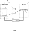
- the coin handling system 100 may further comprise a management apparatus 4, as illustrated in FIG. 5 .
- the management apparatus 4 is a computer such as a server communicably connected to the change dispensers 1 and the coin handling apparatus 2 via a network or the like.
- the cassette 3 does not comprise a memory 40, but management apparatus 4 does.
- the management apparatus 4 may receive the date and time when the emptying of the cassette 3 was performed and the number specifying the coin handling apparatus 2 from the coin handling apparatus 2 and write the information in the memory 40.
- the control unit 26 of the coin handling apparatus 2 may acquire information necessary for the determination from the management apparatus 4.
- the management apparatus 4 may acquire the ID of and the inventory amount in the cassette 3 from the change dispenser 1 or the coin handling apparatus 2, and cause the memory 40 to store the ID and inventory amount regarding the cassette 3 in association with each other. For deciding whether or not the inventory amount in the cassette 3 is 0, the control unit 26 of the coin handling apparatus 2 may acquire the ID from the attached cassette 3 and acquire the inventory amount associated with the acquired ID from the memory 40 of the management apparatus 4.
- the change dispenser 1 may associate the ID and inventory amount regarding the cassette 3 with each other and store the ID and inventory amount in a memory comprised in the change dispenser 1.
- the coin handling apparatus 2 may be communicably connected to the change dispenser 1. In this case, for deciding whether or not the inventory amount in the cassette 3 is 0, the control unit 26 of the coin handling apparatus 2 may acquire the ID from the attached cassette 3 and acquire the inventory amount associated with the acquired ID from the memory of the change dispenser 1.
- the change dispenser 1 may associate the ID and inventory amount regarding the cassette 3 with each other and transmit the ID and inventory amount to the coin handling apparatus 2.
- the coin handling apparatus 2 may associate the received ID and inventory amount regarding the cassette 3 with each other and store the ID and inventory amount in a memory comprised in the coin handling apparatus 2. In this case, for deciding whether or not the inventory amount in the cassette 3 is 0, the control unit 26 of the coin handling apparatus 2 may acquire the ID from the attached cassette 3 and acquire the inventory amount associated with the acquired ID from the memory of the coin handling apparatus 2.
- the present disclosure are applicable in various industrial fields that handle coins, such as distribution and finance.
Landscapes
- Physics & Mathematics (AREA)
- General Physics & Mathematics (AREA)
- Control Of Vending Devices And Auxiliary Devices For Vending Devices (AREA)
- Cash Registers Or Receiving Machines (AREA)
Abstract
Description
- The present disclosure relates to a coin handling apparatus and a coin handling method.
- As disclosed in Patent Literature (hereinafter, referred to as PTL) 1, for example, a coin handling apparatus for handling coins is known.
-
Japanese Patent Application Laid-Open No. H08-287318 - In recent years, it has been proposed to use a cassette that stores coins for transferring coins between a plurality of coin handling apparatuses. The shorter the time required to transfer coins from a coin handling apparatus to a cassette, the better.
- An object of the present disclosure is to provide a money handling apparatus and a money handling method both capable of completing the transferring of coins to a cassette in a short time.
- A coin handling apparatus according to the present disclosure comprises: a cassette attachment unit where a cassette is configured to be attached; a coin supply unit configured to supply a coin to the cassette; and a control unit that causes the cassette attached to the cassette attachment unit to perform a first confirmation operation when the cassette does not satisfy a predetermined condition, the first confirmation operation being an operation for confirming that a coin remains in the cassette, and operates the coin supply unit to supply a coin to the cassette attached to the cassette attachment unit without causing the cassette to perform the first confirmation operation when the cassette satisfies the predetermined condition. The first confirmation operation may be an operation of confirming whether or not a coin remain in the cassette.
- The cassette may comprise a conveyor for transporting coins in the cassette and a sensor for detecting a coin in the cassette.
- The first confirmation operation may be the operation of a conveyor for transporting a coin to a detection area of the sensor.
- When an error occurs in the coin supply unit or the cassette while a coin is being supplied from the coin supply unit to the cassette, the control unit may cause the cassette to perform a second confirmation operation different from the first confirmation operation, the second confirmation operation being for confirming that a coin remains in the cassette. The second confirmation operation may be an operation of confirming whether or not a coin remains in the cassette.
- The second confirmation operation may be a combination of an operation of the conveyor for transporting a coin in a first direction toward the detection area of the sensor and an operation of the conveyor for transporting a coin in a second direction different from the first direction.
- The control unit may be configured to be able to acquire the inventory amount in the cassette.
- When the sensor detects a coin as a result of the first confirmation operation even though the inventory amount is 0, the control unit may generate a signal to notify that the coin has been detected.
- The control unit may be configured to be able to acquire the inventory amount from a memory comprised in the cassette.
- The predetermined condition may be a condition such that the cassette is attached to a cassette attachment unit within a predetermined time after the cassette was last emptied (i.e. the last emptying of the cassette). In addition, the predetermined condition may be a condition such that the cassette is attached to the cassette attachment unit of the coin handling apparatus that has last emptied the cassette. The predetermined condition may be a condition such that both of these conditions are satisfied.
- A coin handling method according to the present disclosure is performed by a coin handling apparatus configured to supply a coin to a cassette, and the coin handling method comprises: determining whether or not the cassette attached to a cassette attachment unit satisfies a predetermined condition; causing the cassette to perform a first confirmation operation for confirming that a coin remains in the cassette when the cassette does not satisfy the predetermined condition; and supplying a coin to the cassette without causing the cassette to perform the first confirmation operation when the cassette satisfies the predetermined condition.
- The present disclosure can provide a money handling apparatus and a money handling method both capable of completing the transferring of coins to a cassette in a short time.
-
-
FIG. 1 is a schematic diagram illustrating a coin handling system according to an embodiment; -
FIG. 2 is a schematic diagram illustrating a coin handling apparatus; -
FIG. 3 is a schematic diagram illustrating a cassette; -
FIG. 4 is a flow chart of a coin handling method; and -
FIG. 5 is a schematic diagram illustrating a coin handling system according to an variation. - Hereinafter, an embodiment according to one aspect of the present disclosure will be described with reference to the drawings.
-
FIG. 1 is a schematic diagram illustrating acoin handling system 100. Thecoin handling system 100 compriseschange dispensers 1, acoin handling apparatus 2, andcassettes 3. - The
change dispenser 1 is disposed at acheckout counter 101. A plurality ofchange dispensers 1 may be disposed at thecheckout counter 101. Thechange dispenser 1 is connected to a POS terminal, a kiosk terminal, or the like, and dispenses banknotes and coins as change necessary for settlement of the purchase price of merchandise. - The coin handling
apparatus 2 is disposed in aback office 102. Thecoin handling apparatus 2 stores coins collected from thechange dispenser 1 and dispenses a change fund required by thechange dispenser 1. - The
cassette 3 is a container used for transferring coins between thechange dispensers 1 and thecoin handling apparatus 2. The number ofcassettes 3 in thecoin handling system 100 may be one, or two or more. In addition, a plurality ofchange dispensers 1 may sharesingle cassette 3. - For example, when the proceeds from sales of a day after the business for the day is finished are transferred from the
change dispenser 1 to the coin handlingapparatus 2, thecassette 3 is attached to thechange dispenser 1 and the coins in thechange dispenser 1 are transferred to thecassette 3. Thecassette 3 with the coins stored therein is then attached to the coin handlingapparatus 2, and the coins are transferred from thecassette 3 to the coin handlingapparatus 2. At this time, thecassette 3 is emptied. - In addition, for example, for transferring a change fund from the
coin handling apparatus 2 to thechange dispenser 1 before the start of business for a day, thecassette 3 is attached to the coin handlingapparatus 2 and coins in the coin handlingapparatus 2 are transferred to thecassette 3. Thecassette 3 with the coins stored therein is then attached to thechange dispenser 1, and the coins are transferred from thecassette 3 to thechange dispenser 1. -
FIG. 2 is a schematic diagram illustrating the coin handlingapparatus 2. The coin handlingapparatus 2 comprises adeposit unit 21, a rotatingdisc 22, and atransport unit 23. Thedeposit unit 21 is configured to allow thecassette 3 to be detachably attached thereto and to receive coins from thecassette 3. Thedeposit unit 21 may be configured to accept loose coins that are manually deposited. The rotatingdisc 22 is configured to supply the coins deposited from thedeposit unit 21 one by one to thetransport unit 23. Thetransport unit 23 is configured to transport coins one by one. - The
coin handling apparatus 2 comprises a plurality ofdiversion units 24, arecognition unit 25, and acontrol unit 26. The plurality ofdiversion units 24 are configured to be able to switch the transport path on which coins are transported by thetransport unit 23. Therecognition unit 25 recognizes coins being transported by thetransport unit 23. Therecognition unit 25 recognizes, for example, the authenticity, denomination, and fitness of the coins. Thecontrol unit 26 controls thediversion unit 24 based on the recognition result of therecognition unit 25 to switch the destination of each coin according to its denomination. - The
coin handling apparatus 2 comprises a plurality ofstorage units 27 and adischarge unit 28. Eachstorage unit 27 is configured to store coins transported through the transport path correspondingly switched by thediversion unit 24. The plurality ofstorage units 27 each store sorted coins in a corresponding denomination. In addition, eachstorage unit 27 is configured to be able to discharge the stored coins one by one onto thedischarge unit 28. Thedischarge unit 28 is configured by, for example, a conveyor belt, and transports the coins discharged from thestorage unit 27. - The
coin handling apparatus 2 comprises acassette attachment unit 29. Thecassette attachment unit 29 is configured in such a way that thecassette 3 can be attached thereto and thecassette 3 can be detached therefrom. In other words, thecassette attachment unit 29 is configured in such a way that thecassette 3 can be detachably attached thereto. A lower unit of thecoin handling apparatus 2 may comprise thecassette attachment unit 29. The lower unit may be configured in such a way that the lower unit can be pulled out from thecoin handling apparatus 2 or pushed into thecoin handling apparatus 2. - The
storage units 27 and thedischarge unit 28 form acoin supply unit 20. Thecoin supply unit 20 is configured to supply coins to thecassette 3 attached to thecassette attachment unit 29. -
FIG. 3 is a schematic diagram illustrating thecassette 3. Thecassette 3 comprises ahousing 31 surrounding astorage space 30. Aninlet 32 is formed on the upper surface of thehousing 31. Thecassette 3 comprises ashutter 33 for the inlet (herein also referred to as "inlet shutter") for opening and closing theinlet 32. Anoutlet 34 is formed on the side surface of thehousing 31. Thecassette 3 comprises ashutter 35 for the outlet (herein also referred to as "outlet shutter") for opening and closing theoutlet 34. Aninlet shutter 33 opens theinlet 32 when coins are supplied to thecassette 3, and otherwise closes theinlet 32. Theoutlet shutter 35 opens theoutlet 34 when coins are discharged from thecassette 3, and otherwise closes theoutlet 34. - The
cassette 3 comprises aconveyor 36, afall prevention plate 37, and asensor 38. Theconveyor 36 forms the bottom portion of thestorage space 30 and supports coinsentering the storage space 30-from theinlet 32, from below. Theconveyor 36 comprises an endless belt and is configured to rotate in both forward and reverse directions. When theconveyor 36 rotates in the forward direction, coins move in the forward direction (direction A inFIG. 3 ), and when the conveyor rotates in the reverse direction, coins move in the reverse direction (direction B inFIG. 3 ). Theconveyor 36 discharges coins out of thecassette 3 through theoutlet 34 by moving the coins in the forward direction. Thefall prevention plate 37 is disposed on the opposite side from theoutlet 34 with theconveyor 36 located therebetween. Thefall prevention plate 37 is inclined in such a way that the further from the bottom, the further from theoutlet 34. In addition, thefall prevention plate 37 is disposed in such a way that the lower end thereof faces the surface of theconveyor 36 with a gap through which coins cannot pass. Thefall prevention plate 37 prevents coins from falling from the top of theconveyor 36. Thesensor 38 is configured to detect coins placed on theconveyor 36, and is, for example, an optical sensor comprising a light-emitting portion and a light-receiving portion. Thesensor 38 is disposed in such a way that thedetection area 39 of thesensor 38 is positioned on the opposite side from theoutlet 34 with theconveyor 36 located therebetween. Theconveyor 36 moves coins, which the conveyor supports, into thedetection area 39 by moving the coins in the reverse direction. - The
conveyor 36 and thefall prevention plate 37 may face each other so as to form a V-shaped recess as illustrated inFIG. 3 . In addition, thesensor 38 may be disposed in such a way that thedetection area 39 includes this V-shaped recess. Such a configuration can obtain the following advantages. By rotating theconveyor 36 in the reverse direction when a few (for example, one) coins are on theconveyor 36, the coin can be erected in the V-shaped recess (surface contact between the coin and theconveyor 36 is released). Thesensor 38 thus can detect coins without fail. - The
cassette 3 is configured to be able to receive electric power supply from thecoin handling apparatus 2 when the cassette is attached to thecassette attachment unit 29. This electric power operates theinlet shutter 33, theoutlet shutter 35, theconveyor 36, and thesensor 38. When thecassette 3 is attached to thecassette attachment unit 29, thecoin handling apparatus 2, specifically thecontrol unit 26, controls thecassette 3. That is, thesensor 38 transmits the detection result to thecontrol unit 26, and theinlet shutter 33, theoutlet shutter 35, and theconveyor 36 receive control signals from thecontrol unit 26. - The
cassette 3 comprises amemory 40. Thememory 40 stores the inventory amount in thecassette 3, that is, the total denomination value of the coins stored in thecassette 3. Thememory 40 also stores information indicating the state of thecassette 3. The information indicating the inventory amount in thecassette 3 and the state of thecassette 3 is written in thememory 40 by the control unit of thechange dispenser 1 or thecontrol unit 26 of thecoin handling apparatus 2 when thecassette 3 is attached to thechange dispenser 1 or thecoin handling apparatus 2. Examples of the information indicating the state of thecassette 3 includes information indicating whether or not thecassette 3 is in a state that requires a detailed examination, information specifying an apparatus that last emptied thecassette 3, and information indicating the last time thecassette 3 was emptied. - In the following, the operation of the
coin handling apparatus 2 when coins are supplied from thecoin handling apparatus 2 to thecassette 3 will be described with reference toFIG. 4. FIG. 4 is a flow chart of a coin handling method performed when coins are supplied from thecoin handling apparatus 2 to thecassette 3. - When the
cassette 3 is attached to thecassette attachment unit 29, thecontrol unit 26 decides whether or not the inventory amount in thecassette 3 is 0 (S1). That is, thecontrol unit 26 decides whether or not thecassette 3 is empty. The inventory amount in thecassette 3 can be acquired from thememory 40. - When the inventory amount in the
cassette 3 acquired from thememory 40 is 0 (Yes in S1), thecontrol unit 26 of thecoin handling apparatus 2 determines whether or not a predetermined condition is satisfied (S2). The predetermined condition is such that the probability that thecassette 3 is empty can be determined to be high. The operation of supplying coins to thecassette 3 whose inventory amount is 0, that is, to theempty cassette 3 is performed, for example, for depositing coins into thecassette 3 as a change fund. A determination as to whether or not the predetermined condition is satisfied may be performed when the lower unit comprising thecassette attachment unit 29 is pulled out from thecoin handling apparatus 2, thecassette 3 is attached to thecassette attachment unit 29, and the position of the lower unit is returned (when the lower unit is pushed into the coin handling apparatus 2). Alternatively, the determination as to whether or not the predetermined condition is satisfied may be performed when coins are supplied from thecoin supply unit 20 to thecassette 3. - When the predetermined condition is not satisfied (No in S2), there is a possibility that the
cassette 3 is not empty, so a simple check is performed to confirm whether or not a coin remains in thecassette 3. That is, thecontrol unit 26 causes thecassette 3 to perform the first confirmation operation (S3). The first confirmation operation is, for example, an operation of rotating theconveyor 36 in the reverse direction. When a coin (herein, "a coin" includes a plurality of coins, and the number of "coins" may be one) remains in thecassette 3, the coin can be detected with thesensor 38 by rotating theconveyor 36 in the reverse direction to move the coin on theconveyor 36 into thedetection area 39 of thesensor 38. The time for rotating theconveyor 36 in the reverse direction may be the time required for the endless belt of theconveyor 36 to make about a half turn (for example, 2 seconds). When the endless belt makes a half turn, even a coin in the vicinity of theoutlet 34 can be brought into thedetection area 39. That is, when a coin remains on theconveyor 36, the coin can be moved into thedetection area 39 without fail by rotating the endless belt halfway. The coin that has moved into thedetection area 39 continues to stay on theconveyor 36 and within thedetection area 39 due to thefall prevention plate 37. - As a result of the first confirmation operation, when the
sensor 38 does not detect any coins, it can be determined that no coins remain, and when thesensor 38 detects a coin, it can be determined that a coin remains. - Therefore, when the
sensor 38 does not detect any coins during the first confirmation operation (No in S4), thecontrol unit 26 operates thecoin supply unit 20, following the first confirmation operation, to supply coins from thecoin supply unit 20 to the cassette 3 (S5). - When the
sensor 38 detects a coin during the first confirmation operation (Yes in S4), thecontrol unit 26 generates a signal to notify that a coin has been detected, and transmits this signal to a notification apparatus capable of alerting an operator. The notification apparatus notifies that a coin has been detected upon receiving this signal (S6). The notification apparatus is, for example, a display, a warning light, or a speaker comprised in thecoin handling apparatus 2, or a computer communicably connected to thecoin handling apparatus 2. - As the operator is notified by the notification apparatus that a coin remains in the
cassette 3, the operator can detach thecassette 3 from thecassette attachment unit 29 to empty the cassette 3 (S7). Further, the operator can attach thecassette 3 to thecassette attachment unit 29 again after emptying thecassette 3. Subsequently, thecontrol unit 26 again determines whether or not the predetermined condition is satisfied (S2). The emptying of thecassette 3 is, for example, attachingcassette 3 to thedeposit unit 21 and transferring a coin from thedeposit unit 21 to thecoin handling apparatus 2. - When the predetermined condition is satisfied (Yes in S2), it can be determined that the
cassette 3 is empty, that is, no coins remain in thecassette 3. Therefore, thecontrol unit 26 operates thecoin supply unit 20 to supply coins from thecoin supply unit 20 to thecassette 3 without causing thecassette 3 to perform the first confirmation operation (S5). - By operating as described above, the
coin handling apparatus 2 supplies coins to thecassette 3 without performing any prior check at all when the probability that thecassette 3 is empty is high. In addition, even when there is a possibility that thecassette 3 is not empty, thecoin handling apparatus 2 supplies coins to thecassette 3 with performing only a simple check that can be completed in a short time. Therefore, thecoin handling apparatus 2 can complete the transferring of coins to thecassette 3 in a short time. As the number ofchange dispensers 1 increases and the number ofcassettes 3 into which change funds are to be placed increases, the effect of shortened waiting time for the transferring of coins to thecassettes 3 in a short time is increased. - As described above, the predetermined condition is such that the probability that the
cassette 3 is empty can be determined to be high. Examples of the predetermined condition include a condition such that a detailed examination of thecassette 3 is not required, a condition such that the apparatus that last emptied thecassette 3 is thecoin handling apparatus 2 itself, and a condition such that a predetermined time has not passed sincecassette 3 was last emptied. - The condition such that a detailed examination of the
cassette 3 is not required is satisfied by no information being written in thememory 40 comprised in the cassette 3-the information indicating that the detailed examination of thecassette 3 is required. Such information indicating that a detailed examination of thecassette 3 is required is written in thememory 40 by thechange dispenser 1. Example of the cases in which such information is written include the following cases: coins have been completely transferred from thecassette 3 to thechange dispenser 1, but a transport error occurs during the transfer; coins cannot be completely transferred from thecassette 3 to thechange dispenser 1; and a transport error occurs while coins are being transferred from thechange dispenser 1 to thecassette 3. - The condition such that the apparatus that last emptied the
cassette 3 is thecoin handling apparatus 2 itself is satisfied by the number specifying thecoin handling apparatus 2 being written in thememory 40 comprised in thecassette 3 as the number specifying the apparatus that last emptied thecassette 3. The number specifying an apparatus is, for example, the apparatus number or the apparatus ID. Here, an exemplary case is assumed as follows: at the end of business for a day, proceeds from sales are collected from thechange dispenser 1 into thecassette 3 and the proceeds from sales are deposited in thecoin handling apparatus 2 from thedeposit unit 21. At this time, thecoin handling apparatus 2 writes its own number in thememory 40. In the next morning, when thecassette 3 is attached to thecassette attachment unit 29 in order to replenish thecassette 3 with a change fund from thecoin handling apparatus 2, thecoin handling apparatus 2 obtains from the memory 40 a number specifying the apparatus that last emptied thecassette 3. When the acquired number is the number of thecoin handling apparatus 2, the condition such that the apparatus that last emptied thecassette 3 is thecoin handling apparatus 2 itself is satisfied. - The condition such that a predetermined time has not passed since the
cassette 3 was last emptied is satisfied by the predetermined time having not passed at the time when thecassette 3 is attached to thecassette attachment unit 29 since the last time thecassette 3 was emptied. An apparatus that empties thecassette 3 writes the time (i.e., date and time) in thememory 40 each time the apparatus empties the cassette. When a certain amount of time has passed since the last written time, that is, sincecassette 3 was last emptied, there is a possibility that some event has occurred in thecassette 3 and a coin have entered thecassette 3 during the certain amount of time. Therefore, by satisfying the condition such that the predetermined time has not passed sincecassette 3 was last emptied, it can be determined that the probability that the cassette remains empty is high. The predetermined time may be, for example, one month or one year. - In the following, the operation to be performed when the inventory amount in the
cassette 3 acquired from thememory 40 is not 0 will be described. This operation is performed, for example, when thecassette 3 is additionally replenished with a change fund during business hours. - When the inventory amount in the
cassette 3 acquired from thememory 40 is not 0 (No in S1), a first confirmation operation, which is a simple check for confirming whether or not a coin remains in thecassette 3, may be performed (S8). - As a result of the first confirmation operation, when the
sensor 38 detects a coin (Yes in S9), the detection result matches the information in thememory 40 indicating that the inventory amount is not zero. Therefore, following the first confirmation operation, thecontrol unit 26 operates thecoin supply unit 20 to supply coins from thecoin supply unit 20 to the cassette 3 (S5). At this time, thecontrol unit 26 writes in thememory 40 the sum of the total denomination value of the coins supplied to thecassette 3 and the inventory amount stored in thememory 40 as a new inventory amount. - As a result of the first confirmation operation, when the
sensor 38 does not detect any coins (No in S9), the detection result does not match the information in thememory 40 indicating that the inventory amount is not zero. However, the first confirmation operation is an operation of a simple check; therefore, the absence of coins in thecassette 3 cannot be fully guaranteed on the basis that thesensor 38 does not detect any coins during the first confirmation operation. Therefore, in this case, the process such that the inventory amount stored in thememory 40 is defined as correct (S10). Subsequently, thecontrol unit 26 operates thecoin supply unit 20 to supply coins from thecoin supply unit 20 to the cassette 3 (S5). At this time, thecontrol unit 26 writes in thememory 40 the sum of the total denomination value of the coins supplied to thecassette 3 and the inventory amount stored in thememory 40 as a new inventory amount. - When the inventory amount in the
cassette 3 acquired from thememory 40 is not 0, thecontrol unit 26 may operate thecoin supply unit 20 to supply coins from thecoin supply unit 20 to thecassette 3 without causing thecassette 3 to perform the first confirmation operation (see the broken line inFIG. 4 ). - Regardless of the inventory amount in the
cassette 3 before the supplying of coins to thecassette 3, when an error occurs while coins are being supplied to thecassette 3, the processing of supplying coins to thecassette 3 may be continued as described below. The error in the present embodiment is an error such as a coin jam in thecoin supply unit 20 or in thecassette 3. - When an error such as a coin jam does not occur while coins are being supplied from the
coin supply unit 20 to the cassette 3 (S5) (No in S11), the supplying of coins from thecoin supply unit 20 to thecassette 3 is completed. - When an error such as a coin jam occurs while coins are being supplied from the
coin supply unit 20 to the cassette 3 (Yes in S11), thecontrol unit 26 may generate a signal to notify that the error has occurred and send this signal to the notification apparatus. The notification apparatus may notify that an error has occurred upon receiving this signal (S12). - As the operator is notified by the notification apparatus that an error has occurred, the operator can detach the
cassette 3 from thecassette attachment unit 29 to empty the cassette 3 (S13). Further, the operator can attach thecassette 3 to thecassette attachment unit 29 again after emptying thecassette 3. - Subsequently, the
control unit 26 may cause thecassette 3 to perform a second confirmation operation that is different from the first confirmation operation (S14). The second confirmation operation is a combination of the operation of theconveyor 36 that moves coins toward the outlet 34 (that is, forward rotation) and the operation of theconveyor 36 that moves coins toward thedetection area 39 of the sensor 38 (that is, reverse rotation). The second confirmation operation may be an operation of rotating theconveyor 36 in the forward and reverse directions a plurality of times. Thesensor 38 can detect any coins remaining in thecassette 3 without fail by alternately rotating theconveyor 36 forward and backward a plurality of times. In other words, the second confirmation operation is a strict check for detecting a coin remaining in thecassette 3 without fail. The second confirmation operation is performed, for example, for 15 seconds. - As a result of the second confirmation operation, when the
sensor 38 does not detect any coins, it can be determined without fail that no coins remain, and when thesensor 38 detects a coin, it can be determined that a coin remains. - Therefore, when the
sensor 38 does not detect any coins during the second confirmation operation (No in S15), thecontrol unit 26 operates thecoin supply unit 20, following the second confirmation operation, to supply coins from thecoin supply unit 20 to the cassette 3 (S5). - When the
sensor 38 detects a coin during the second confirmation operation (Yes in S15), thecontrol unit 26 generates a signal to notify that a coin has been detected, and transmits this signal to the notification apparatus. The notification apparatus notifies that a coin has been detected upon receiving this signal (S12). Subsequent operations are as described above. - The
coin handling apparatus 2 according to the present disclosure that operates as described above has advantages as follows. When, for example, it is necessary to continuously send a change funds to a plurality ofempty cassettes 3, such as during the time period for making preparations for starting day's business, such a coin handling apparatus can complete the supply of coins to eachcassette 3 in a short time. Specifically, the supplying of coins is started in the following cases: when a predetermined condition is satisfied, no operation is performed for confirming whether or not thecassette 3 is empty; and even when the predetermined condition is not satisfied, only a simple check, which is completed in a much shorter time than the strict check, is performed. Therefore, the waiting time for the transferring of coins for eachcassette 3 can be shortened, and preparations for starting a day's business can be quickly made. Even when there is only oneempty cassette 3 waiting for the supplying of coins, coins can be supplied without performing a strict check, as long as no error occurs while coins are being supplied. Therefore, the supply of coins can also be completed in a short time for only oneempty cassette 3. - The present disclosure is not limited to the embodiment described above, and various modifications can be made without departing from the spirit of the present disclosure.
- For example, the
coin handling system 100 may further comprise amanagement apparatus 4, as illustrated inFIG. 5 . Themanagement apparatus 4 is a computer such as a server communicably connected to thechange dispensers 1 and thecoin handling apparatus 2 via a network or the like. Thecassette 3 does not comprise amemory 40, butmanagement apparatus 4 does. In this case, when coins are transferred from thecassette 3 to thecoin handling apparatus 2 to empty thecassette 3, themanagement apparatus 4 may receive the date and time when the emptying of thecassette 3 was performed and the number specifying thecoin handling apparatus 2 from thecoin handling apparatus 2 and write the information in thememory 40. For determining whether or not the predetermined condition is satisfied, thecontrol unit 26 of thecoin handling apparatus 2 may acquire information necessary for the determination from themanagement apparatus 4. Themanagement apparatus 4 may acquire the ID of and the inventory amount in thecassette 3 from thechange dispenser 1 or thecoin handling apparatus 2, and cause thememory 40 to store the ID and inventory amount regarding thecassette 3 in association with each other. For deciding whether or not the inventory amount in thecassette 3 is 0, thecontrol unit 26 of thecoin handling apparatus 2 may acquire the ID from the attachedcassette 3 and acquire the inventory amount associated with the acquired ID from thememory 40 of themanagement apparatus 4. - For transferring coins to the
cassette 3, thechange dispenser 1 may associate the ID and inventory amount regarding thecassette 3 with each other and store the ID and inventory amount in a memory comprised in thechange dispenser 1. Thecoin handling apparatus 2 may be communicably connected to thechange dispenser 1. In this case, for deciding whether or not the inventory amount in thecassette 3 is 0, thecontrol unit 26 of thecoin handling apparatus 2 may acquire the ID from the attachedcassette 3 and acquire the inventory amount associated with the acquired ID from the memory of thechange dispenser 1. For transferring coins to thecassette 3, thechange dispenser 1 may associate the ID and inventory amount regarding thecassette 3 with each other and transmit the ID and inventory amount to thecoin handling apparatus 2. Thecoin handling apparatus 2 may associate the received ID and inventory amount regarding thecassette 3 with each other and store the ID and inventory amount in a memory comprised in thecoin handling apparatus 2. In this case, for deciding whether or not the inventory amount in thecassette 3 is 0, thecontrol unit 26 of thecoin handling apparatus 2 may acquire the ID from the attachedcassette 3 and acquire the inventory amount associated with the acquired ID from the memory of thecoin handling apparatus 2. - The present disclosure are applicable in various industrial fields that handle coins, such as distribution and finance.
-
- 1 Change dispenser
- 2 Coin handling apparatus
- 3 Cassette
- 4 Management apparatus
- 20 Coin supply unit
- 21 Deposit unit
- 22 Rotating disc
- 23 Transport unit
- 24 Diversion unit
- 25 Recognition unit
- 26 Control unit
- 27 Storage unit
- 28 Discharge unit
- 29 Cassette attachment unit
- 30 Storage space
- 31 Housing
- 32 Inlet
- 33 Inlet shutter
- 34 Outlet
- 35 Outlet shutter
- 36 Conveyor
- 37 Fall prevention plate
- 38 Sensor
- 39 Detection area
- 40 Memory
- 100 Coin handling system
- 101 Checkout counter
- 102 Back office
Claims (9)
- A coin handling apparatus, comprising:a cassette attachment unit where a cassette is configured to be attached;a coin supply unit configured to supply a coin to the cassette; anda control unit thatcauses the cassette attached to the cassette attachment unit to perform a first confirmation operation when the cassette does not satisfy a predetermined condition, the first confirmation operation being an operation for confirming that a coin remains in the cassette, andoperates the coin supply unit to supply a coin to the cassette attached to the cassette attachment unit without causing the cassette to perform the first confirmation operation when the cassette satisfies the predetermined condition.
- The coin handling apparatus according to claim 1, wherein:the cassette comprises a conveyor configured to transport a coin in the cassette and a sensor configured to detect a coin in the cassette; andthe first confirmation operation is an operation of the conveyor for transporting a coin to a detection area of the sensor.
- The coin handling apparatus according to claim 2, wherein
when an error occurs in the coin supply unit or the cassette while a coin is being supplied from the coin supply unit to the cassette, the control unit causes the cassette to perform a second confirmation operation different from the first confirmation operation, the second confirmation operation being for confirming that a coin remains in the cassette. - The coin handling apparatus according to claim 3, wherein
the second confirmation operation comprises an operation of the conveyor for transporting a coin in a first direction toward the detection area of the sensor and an operation of the conveyor for transporting a coin in a second direction different from the first direction. - The coin handling apparatus according to any one of claims 2 to 4, whereinthe control unit is configured to acquire an inventory amount in the cassette; andwhen the sensor detects a coin as a result of the first confirmation operation even though the inventory amount is 0, the control unit generates a signal to notify that a coin has been detected.
- The coin handling apparatus according to claim 5, wherein
the control unit is configured to acquire the inventory amount from a memory comprised in the cassette. - The coin handling apparatus according to any one of claims 1 to 6, wherein
the predetermined condition is a condition such that the cassette is attached to the cassette attachment unit within a predetermined time after last emptying of the cassette. - The coin handling apparatus according to any one of claims 1 to 7, wherein
the predetermined condition is a condition such that the cassette is attached to the cassette attachment unit of the coin handling apparatus having last emptied the cassette. - A coin handling method that is performed by a coin handling apparatus configured to supply a coin to a cassette, the coin handling method comprising:determining whether or not the cassette attached to a cassette attachment unit satisfies a predetermined condition;causing the cassette to perform a first confirmation operation when the cassette does not satisfy a predetermined condition, the first confirmation operation being an operation for confirming that a coin remains in the cassette; andsupplying a coin to the cassette without causing the cassette to perform the first confirmation operation when the cassette satisfies the predetermined condition.
Applications Claiming Priority (1)
| Application Number | Priority Date | Filing Date | Title |
|---|---|---|---|
| JP2022041848A JP2023136310A (en) | 2022-03-16 | 2022-03-16 | Coin processing device and coin processing method |
Publications (2)
| Publication Number | Publication Date |
|---|---|
| EP4246472A1 true EP4246472A1 (en) | 2023-09-20 |
| EP4246472B1 EP4246472B1 (en) | 2026-05-06 |
Family
ID=85640775
Family Applications (1)
| Application Number | Title | Priority Date | Filing Date |
|---|---|---|---|
| EP23161777.0A Active EP4246472B1 (en) | 2022-03-16 | 2023-03-14 | Coin handling apparatus and coin handling method |
Country Status (3)
| Country | Link |
|---|---|
| US (1) | US12183146B2 (en) |
| EP (1) | EP4246472B1 (en) |
| JP (1) | JP2023136310A (en) |
Citations (3)
| Publication number | Priority date | Publication date | Assignee | Title |
|---|---|---|---|---|
| JPH08287318A (en) | 1995-04-10 | 1996-11-01 | Omron Corp | Reverse roller hopper and coin handling device |
| US20120012437A1 (en) * | 2009-03-19 | 2012-01-19 | Glory Ltd. | Money handling machine |
| US20210390815A1 (en) * | 2020-06-12 | 2021-12-16 | Glory Ltd. | Money handling apparatus and money handling method |
Family Cites Families (15)
| Publication number | Priority date | Publication date | Assignee | Title |
|---|---|---|---|---|
| US5938072A (en) * | 1997-09-16 | 1999-08-17 | Magner Corporation | Rolled coin dispenser |
| US9004352B1 (en) * | 1998-11-25 | 2015-04-14 | Diebold Self-Service Systems Division Of Diebold, Incorporated | Banking system controlled responsive to data read from data bearing records |
| US6230928B1 (en) * | 1998-11-25 | 2001-05-15 | Diebold, Incorporated | Automated merchant banking apparatus and method |
| US8800864B2 (en) * | 1998-11-25 | 2014-08-12 | Diebold, Incorporated | Banking system controlled responsive to data read from data bearing records |
| US7883005B2 (en) * | 1998-11-25 | 2011-02-08 | Diebold, Incorporated | Banking system controlled by data bearing records |
| US8590780B2 (en) * | 1998-11-25 | 2013-11-26 | Diebold, Incorporated | Banking system controlled responsive to data read from data bearing records |
| US9934640B2 (en) * | 2004-09-15 | 2018-04-03 | Cummins-Allison Corp. | System, method and apparatus for repurposing currency |
| CA2660418C (en) * | 2008-03-25 | 2018-08-07 | Cummins-Allison Corp. | Self service coin redemption card printer-dispenser |
| US8545295B2 (en) * | 2010-12-17 | 2013-10-01 | Cummins-Allison Corp. | Coin processing systems, methods and devices |
| US9355531B2 (en) * | 2012-12-18 | 2016-05-31 | Diebold Self-Service Systems, Division Of Diebold, Incorporated | Deposit management system that employs preregistered deposits |
| JP6467968B2 (en) * | 2015-02-16 | 2019-02-13 | 沖電気工業株式会社 | Media delivery device |
| US9875593B1 (en) * | 2015-08-07 | 2018-01-23 | Cummins-Allison Corp. | Systems, methods and devices for coin processing and coin recycling |
| US10896566B2 (en) * | 2017-09-04 | 2021-01-19 | Asahi Seiko Co., Ltd. | Coin recycle device |
| US11170598B2 (en) * | 2019-09-17 | 2021-11-09 | Whirlpool Corporation | Token collection assembly |
| JP2022086209A (en) * | 2020-11-30 | 2022-06-09 | グローリー株式会社 | Coin processor |
-
2022
- 2022-03-16 JP JP2022041848A patent/JP2023136310A/en active Pending
-
2023
- 2023-03-14 US US18/121,020 patent/US12183146B2/en active Active
- 2023-03-14 EP EP23161777.0A patent/EP4246472B1/en active Active
Patent Citations (3)
| Publication number | Priority date | Publication date | Assignee | Title |
|---|---|---|---|---|
| JPH08287318A (en) | 1995-04-10 | 1996-11-01 | Omron Corp | Reverse roller hopper and coin handling device |
| US20120012437A1 (en) * | 2009-03-19 | 2012-01-19 | Glory Ltd. | Money handling machine |
| US20210390815A1 (en) * | 2020-06-12 | 2021-12-16 | Glory Ltd. | Money handling apparatus and money handling method |
Also Published As
| Publication number | Publication date |
|---|---|
| US20230298422A1 (en) | 2023-09-21 |
| EP4246472B1 (en) | 2026-05-06 |
| JP2023136310A (en) | 2023-09-29 |
| US12183146B2 (en) | 2024-12-31 |
Similar Documents
| Publication | Publication Date | Title |
|---|---|---|
| JP5125136B2 (en) | Cash management system | |
| JP2013114300A (en) | Coin handling device, self-checkout terminal device, and coin handling method | |
| JP2023133938A (en) | Coin storage method and coin storage device | |
| EP4246472B1 (en) | Coin handling apparatus and coin handling method | |
| JP5505466B2 (en) | Cash management system and cash data management device | |
| JP7267075B2 (en) | Deposit/withdrawal device, deposit/withdrawal system, and deposit/withdrawal method | |
| JP5087848B2 (en) | Cash management system | |
| JP2021120819A (en) | Automatic change machine and depositing/dispensing control method for money processing device | |
| JP2016118876A (en) | Currency management device and currency management method | |
| US12488649B2 (en) | Sheet handling apparatus and sheet handling method | |
| JP2015064789A (en) | Coin processing machine, coin processing system and coin processing method | |
| JP2018101188A (en) | Currency processor and currency processing system | |
| JP6749769B2 (en) | Money handling system and money deposit and withdrawal machine | |
| JP6726049B2 (en) | Money handling system and money handling method | |
| JP6792503B2 (en) | Money processing machine and money processing method | |
| JP7293721B2 (en) | money handling device | |
| EP4693238A1 (en) | Currency depositing device, currency processing system, and currency processing method | |
| JP2017049679A (en) | Money handling apparatus and money handling method | |
| EP4064233A1 (en) | Money processing device | |
| JP7327024B2 (en) | money handling machine | |
| TW201923716A (en) | Money processing device | |
| JP2019032635A (en) | Settlement device, settlement system, and troubleshooting method | |
| JPH04205292A (en) | Automatic teller machine | |
| JP2001357431A (en) | Coin handling equipment and vending machines | |
| CA3090368A1 (en) | Coin dispensing method, cash transaction apparatus, and coin dispensing program |
Legal Events
| Date | Code | Title | Description |
|---|---|---|---|
| PUAI | Public reference made under article 153(3) epc to a published international application that has entered the european phase |
Free format text: ORIGINAL CODE: 0009012 |
|
| STAA | Information on the status of an ep patent application or granted ep patent |
Free format text: STATUS: REQUEST FOR EXAMINATION WAS MADE |
|
| 17P | Request for examination filed |
Effective date: 20230314 |
|
| AK | Designated contracting states |
Kind code of ref document: A1 Designated state(s): AL AT BE BG CH CY CZ DE DK EE ES FI FR GB GR HR HU IE IS IT LI LT LU LV MC ME MK MT NL NO PL PT RO RS SE SI SK SM TR |
|
| RBV | Designated contracting states (corrected) |
Designated state(s): AL AT BE BG CH CY CZ DE DK EE ES FI FR GB GR HR HU IE IS IT LI LT LU LV MC ME MK MT NL NO PL PT RO RS SE SI SK SM TR |
|
| P01 | Opt-out of the competence of the unified patent court (upc) registered |
Free format text: CASE NUMBER: APP_38251/2024 Effective date: 20240627 |
|
| GRAP | Despatch of communication of intention to grant a patent |
Free format text: ORIGINAL CODE: EPIDOSNIGR1 |
|
| STAA | Information on the status of an ep patent application or granted ep patent |
Free format text: STATUS: GRANT OF PATENT IS INTENDED |
|
| INTG | Intention to grant announced |
Effective date: 20251128 |
|
| GRAS | Grant fee paid |
Free format text: ORIGINAL CODE: EPIDOSNIGR3 |
|
| GRAA | (expected) grant |
Free format text: ORIGINAL CODE: 0009210 |
|
| STAA | Information on the status of an ep patent application or granted ep patent |
Free format text: STATUS: THE PATENT HAS BEEN GRANTED |
|
| AK | Designated contracting states |
Kind code of ref document: B1 Designated state(s): AL AT BE BG CH CY CZ DE DK EE ES FI FR GB GR HR HU IE IS IT LI LT LU LV MC ME MK MT NL NO PL PT RO RS SE SI SK SM TR |
|
| REG | Reference to a national code |
Ref country code: CH Ref legal event code: F10 Free format text: ST27 STATUS EVENT CODE: U-0-0-F10-F00 (AS PROVIDED BY THE NATIONAL OFFICE) Effective date: 20260506 Ref country code: GB Ref legal event code: FG4D |