EP4246274A1 - Automatic steering device, automatic steering system, automatic steering method and program - Google Patents
Automatic steering device, automatic steering system, automatic steering method and program Download PDFInfo
- Publication number
- EP4246274A1 EP4246274A1 EP23161546.9A EP23161546A EP4246274A1 EP 4246274 A1 EP4246274 A1 EP 4246274A1 EP 23161546 A EP23161546 A EP 23161546A EP 4246274 A1 EP4246274 A1 EP 4246274A1
- Authority
- EP
- European Patent Office
- Prior art keywords
- evaluation value
- upper limit
- ship
- automatic steering
- control parameter
- Prior art date
- Legal status (The legal status is an assumption and is not a legal conclusion. Google has not performed a legal analysis and makes no representation as to the accuracy of the status listed.)
- Pending
Links
- 238000000034 method Methods 0.000 title claims description 7
- 238000011156 evaluation Methods 0.000 claims abstract description 175
- 230000003247 decreasing effect Effects 0.000 claims description 11
- 230000007423 decrease Effects 0.000 description 5
- 238000012545 processing Methods 0.000 description 5
- 238000004891 communication Methods 0.000 description 4
- 238000010586 diagram Methods 0.000 description 4
- 230000001133 acceleration Effects 0.000 description 1
- 230000003044 adaptive effect Effects 0.000 description 1
- 230000006866 deterioration Effects 0.000 description 1
- 239000000446 fuel Substances 0.000 description 1
- 239000004973 liquid crystal related substance Substances 0.000 description 1
- 238000012423 maintenance Methods 0.000 description 1
Images


Classifications
-
- G—PHYSICS
- G05—CONTROLLING; REGULATING
- G05D—SYSTEMS FOR CONTROLLING OR REGULATING NON-ELECTRIC VARIABLES
- G05D1/00—Control of position, course, altitude or attitude of land, water, air or space vehicles, e.g. using automatic pilots
- G05D1/02—Control of position or course in two dimensions
- G05D1/0206—Control of position or course in two dimensions specially adapted to water vehicles
-
- B—PERFORMING OPERATIONS; TRANSPORTING
- B63—SHIPS OR OTHER WATERBORNE VESSELS; RELATED EQUIPMENT
- B63H—MARINE PROPULSION OR STEERING
- B63H25/00—Steering; Slowing-down otherwise than by use of propulsive elements; Dynamic anchoring, i.e. positioning vessels by means of main or auxiliary propulsive elements
- B63H25/06—Steering by rudders
-
- B—PERFORMING OPERATIONS; TRANSPORTING
- B63—SHIPS OR OTHER WATERBORNE VESSELS; RELATED EQUIPMENT
- B63H—MARINE PROPULSION OR STEERING
- B63H25/00—Steering; Slowing-down otherwise than by use of propulsive elements; Dynamic anchoring, i.e. positioning vessels by means of main or auxiliary propulsive elements
- B63H25/02—Initiating means for steering, for slowing down, otherwise than by use of propulsive elements, or for dynamic anchoring
- B63H25/04—Initiating means for steering, for slowing down, otherwise than by use of propulsive elements, or for dynamic anchoring automatic, e.g. reacting to compass
Definitions
- the present disclosure relates to an art for automatically controlling a rudder angle.
- Parameters for controlling a rudder angle of an autopilot often use fixed values. If the fixed values are used as the control parameters, the control may not suitably be performed according to the cargo weight and the weather. Thus, a deterioration of the control accuracy and an excessive steering may be induced.
- JP2003-104291A and JP2006-044411A disclose arts for automatically controlling the rudder angle.
- control parameters are adjusted after the cruise. That is, the control parameters may be unsuitable until the control parameters are adjusted.
- the shake of the heading caused by waves is estimated by an estimator. That is, it is necessary to construct the estimator, and the control algorithm becomes complicated. In addition, it is necessary to set parameters for the estimator, and the adjustment may become further complicated.
- one purpose of the present disclosure is to provide an adaptive setting technique for control parameters, which can realize a stable ship control corresponding to changes in internal and external environments which have influences on traveling of a ship.
- an automatic steering device which includes an acquiring module, a first evaluating module, a second evaluating module, and a control parameter setting module.
- the acquiring module acquires a traveling state including a heading or a position of a ship, and ship information on the ship.
- the first evaluating module calculates a first evaluation value which is an evaluation value indicative of a performance for maintaining the heading of the ship or a route based on the traveling state.
- the second evaluating module calculates a second evaluation value which is an evaluation value related to a ship handling control based on the ship information.
- the control parameter setting module sets a control parameter related to a motion control of the ship based on the first evaluation value or the second evaluation value.
- the control parameter can be set based on the first evaluation value which is indicative of the performance for maintaining the heading of the ship or the route based on the traveling state, and the second value which is related to the ship handling control based on control information. Therefore, the control parameter which takes the ship characteristics and the weather into consideration and can realize a stable control according to the condition of the ship can be set.
- control parameter setting module may set the control parameter so that one of the first evaluation value and the second evaluation value which is higher in influence to an unstable motion of the ship is decreased.
- control can be performed according to the ship condition.
- the automatic steering device of this aspect may further include an upper limit setting module which sets a first upper limit corresponding to the first evaluation value and a second upper limit corresponding to the second evaluation value.
- the control parameter setting module may adjust the control parameter based on a relationship between the first evaluation value and the second evaluation value.
- control parameter setting module may set the control parameter so that one of the first evaluation value and the second evaluation value of which the ratio is higher is decreased, based on a comparison of a ratio of the first evaluation value and the first upper limit, and a ratio of the second evaluation value and the second upper limit.
- control can be performed according to the ship condition.
- the upper limit setting module (107) may raise the first upper limit (E ⁇ m) and the second upper limit (E ⁇ m) when the first evaluation value (E ⁇ ) is higher than the first upper limit (E ⁇ m) and the second evaluation value (E ⁇ ) is higher than the second upper limit (E ⁇ m).
- the control parameter can be set more according to the actual cruise.
- the upper limit setting module (107) may reduce the first upper limit (E ⁇ m) or the second upper limit (E ⁇ m) for which the evaluation value (E ⁇ , E ⁇ ) is lower than the upper limit (E ⁇ m, E ⁇ m) when a state where the first evaluation value (E ⁇ ) is lower than the first upper limit (E ⁇ m) or the second evaluation value (E ⁇ ) is lower than the second upper limit (E ⁇ m) continues for more than a given period of time.
- the upper limits are continuously set to be unnecessarily high, and the upper limits can be set according to the actual cruise of the ship. That is, the control parameter can be set more according to the actual cruise.
- control parameter setting module (105) may set the control parameter so that one of the first evaluation value (E ⁇ ) and the second evaluation value (E ⁇ ) that is higher than the upper limit (E ⁇ m, E ⁇ m) is decreased when the first evaluation value (E ⁇ ) is higher than the first upper limit (E ⁇ m) or the second evaluation value (E ⁇ ) is higher than the second upper limit (E ⁇ m).
- the evaluation value among the first evaluation value and the second evaluation value which is problematic in the control is decreased, and thus, the control parameter which can realize the stable control can be set.
- control parameter setting module (105) may lower a control gain when the second evaluation value (E ⁇ ) is higher than the second upper limit (E ⁇ m), and the control parameter setting module (105) raises the control gain when the first evaluation value (E ⁇ ) is higher than the first upper limit (E ⁇ m).
- control parameter can be set suitably according to the influence on the control of the ship given by the direction maintaining performance and the steering amount.
- the automatic steering device of this aspect may further include a mode setting module (106) configured to determine a specific pair from a plurality of pairs of the first upper limit (E ⁇ m) and the second upper limit (E ⁇ m) that are set beforehand.
- the upper limit setting module (107) may set values of the specific pair determined by the mode setting module (106) as initial values of the first upper limit (E ⁇ m) and the second upper limit (E ⁇ m).
- control parameter intended by the user can be determined more easily.
- the traveling state may be a ship heading of the ship.
- the first evaluation value may be an evaluation value of heading maintaining performance which is a performance for maintaining the heading.
- the first evaluating module may calculate the first evaluation value based on a standard deviation of a heading difference.
- the ship information may be a rudder angle of the ship.
- the second evaluation value may be an evaluation value of a steering amount.
- the second evaluating module may calculate the second evaluation value based on an average value of absolute values of the rudder angle measured in a given period of time.
- the average value of the rudder angles in the given period can be obtained. That is, the second evaluation value can be obtained from the actual rudder angle behavior.
- an automatic steering system includes the automatic steering device and a command rudder angle calculating module.
- the command rudder angle calculating module calculates a command rudder angle based on the control parameter set by the control parameter setting module.
- the command rudder angle can be set suitably by using the suitable control parameter.
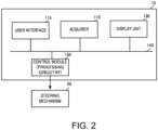
- FIGS. 1 and 2 are functional block diagrams illustrating configurations of the automatic steering device according to this embodiment of the present disclosure.
- the control parameters may be determined by a relationship between a direction maintaining performance and a steering amount.
- This relationship between the direction maintaining performance and the steering amount may be a trade-off relationship. In detail, if the direction maintaining performance is improved (a control gain is raised), the steering amount may increase. On the other hand, if the steering amount is reduced (the control gain is lowered), the direction maintaining performance may be deteriorated.
- control parameters it may be necessary to set the control parameters in consideration of this relationship. That is, it may be preferred to calculate evaluation values for the direction maintaining performance and the steering amount, and set the control parameters so that the evaluation values are below reference values.
- the control parameters may be obtained according to the ship characteristics (the size, the weight, etc.) and the weather (oceanographic conditions), while balancing the direction maintaining performance and the steering amount.
- the detailed configuration of an automatic steering device 10 is described below.
- the automatic steering device 10 may be provided to a ship, along with a steering mechanism 20.
- the ship may behave according to a rudder angle which is controlled by the steering mechanism 20.
- the steering mechanism 20 may be controlled so that the rudder angle becomes a command rudder angle from the automatic steering device 10.
- the ship may realize going straight and making a turn by the rudder angle.
- the automatic steering device 10 may be provided with an acquiring module 110, a user interface 115, a display unit 130, and a control module 150 (or “processing circuitry").
- the automatic steering device 10 may be provided to a ship which performs an autopilot control (automatic navigation control).
- the automatic steering device 10 may connect to the steering mechanism 20.
- the steering mechanism 20 may be provided to various kinds of propelling devices, such as an outboard motor (engine), an inboard motor (engine), and an inboard-outdrive motor (engine).
- the acquiring module 110, the user interface 115, the display unit 130, and the control module 150 may connect to each other via a ship data communication network 140.
- the acquiring module 110, the user interface 115, and the control module 150 may connect to each other, for example, via a propulsion communication network (CAN etc.).
- the control module 150 and the steering mechanism 20 may connect to each other via analog voltage or data communications.
- the user interface 115 is realized, for example, by a touch panel, physical button(s), and/or physical switch(es).
- the user interface 115 may accept operation for setup of control parameters described below.
- the user interface 115 may output the control parameters to the control module 150.
- the display unit 130 is realized, for example, by a liquid crystal panel.
- the display unit 130 may display information relevant to the control parameters inputted from the control module 150. Note that the display unit 130 may be omitted but the display unit 130 may be preferred to be provided so that a user can easily grasp a controlling state and a traveling state.
- Fig. 1 is a more-detailed functional block diagram of the automatic steering device 10 in Fig. 2 . Note that, in Fig. 1 , the configurations of the user interface 115 and the display unit 130 are omitted.
- the acquiring module 110 may include a heading acquiring module 101 and a rudder angle acquiring module 103.
- the control module 150 may include an evaluating module 120, a control parameter setting module 105, a mode setting module 106, an upper limit setting module 107, and a command rudder angle calculating module 108.
- the evaluating module 120 may include a first evaluating module 102 and a second evaluating module 104.
- the heading acquiring module 101 is comprised of, for example, a magnetic sensor, an acceleration sensor, a satellite compass, and/or a GNSS receiver.
- the heading acquiring module 101 may detect a traveling state which includes a direction of the bow (bow direction or heading) or a position of the ship by using the sensor(s).
- the heading acquiring module 101 may output the traveling state to the first evaluating module 102. Note that the example below will be described while assuming that the traveling state is the heading.
- the first evaluating module 102 may evaluate a latest direction maintaining performance based on time-series data of the heading.
- the first evaluating module 102 may calculate a standard deviation of a heading difference or azimuth angle difference (drift angle) as an evaluation value.
- the evaluation value calculated by the first evaluating module 102 may be treated as a first evaluation value E ⁇ .
- the first evaluation value E ⁇ may be an evaluation value indicative of a performance for maintaining the heading (the direction of the ship) or the route.
- the first evaluation value E ⁇ may increase as the direction maintaining performance deteriorates.
- the first evaluating module 102 may output the first evaluation value E ⁇ to the control parameter setting module 105.
- the rudder angle acquiring module 103 is comprised of, for example, a rudder angle sensor.
- the rudder angle acquiring module 103 may detect ship information by using the rudder angle sensor.
- the rudder angle acquiring module 103 may output the ship information to the second evaluating module 104. Note that the example below will be described while assuming that the ship information is a rudder angle.
- the second evaluating module 104 may evaluate a latest steering amount based on time-series data of the rudder angle. In more detail, the second evaluating module 104 may calculate an absolute value of the rudder angle, and calculate an average of the absolute values for 1 second as an evaluation value of the steering amount. The evaluation value calculated by the second evaluating module 104 may be treated as a second evaluation value E ⁇ . The second evaluation value E ⁇ may be an evaluation value related to a ship handling control based on the ship information.
- the control parameter setting module 105 may determine whether the first evaluation value E ⁇ or the second evaluation value E ⁇ is an appropriate value. Then, the control parameter setting module 105 may set the control parameters based on the determination result of whether the first evaluation value E ⁇ or the second evaluation value E ⁇ is the appropriate value. In more detail, for example, the control parameter setting module 105 may compare a ratio of the first evaluation value E ⁇ and a first upper limit E ⁇ m with a ratio of the second evaluation value E ⁇ and a second upper limit E ⁇ m, and set the control parameters so that one of the first evaluation value E ⁇ and the second evaluation value E ⁇ of which the ratio is higher is decreased. The control parameter setting module 105 may output these control parameters to the command rudder angle calculating module 108.
- the mode setting module 106 may determine a mode based on the user's intention. This mode includes, for example, a mode in which course keeping accuracy is considered to be important (a course keeping accuracy oriented mode), and a mode in which a reduction of the steering amount is considered to be important (a steering amount reduction oriented mode). The mode may be determined based on a combination of the first upper limit E ⁇ m and the second upper limit E ⁇ m. In more detail, the mode setting module 106 may set a plurality of combinations of the first upper limit E ⁇ m and the second upper limit E ⁇ m. A user may select a desired mode corresponding to one of the combinations.
- the mode setting module 106 can determine the first upper limit E ⁇ m and the second upper limit E ⁇ m which are intended by the user.
- the upper limit setting module 107 may acquire the mode intended by the user from the mode setting module 106. According to the selected mode, the upper limit setting module 107 may set the upper limit for the first evaluation value E ⁇ as the first upper limit E ⁇ m, and set the upper limit for the second evaluation value E ⁇ as the second upper limit E ⁇ m. Note that initial values of the first upper limit E ⁇ m and the second upper limit E ⁇ m may be determined to be values according to the ship characteristics or the oceanographic conditions, or according to the history of values set in the past.
- the command rudder angle calculating module 108 may calculate a command rudder angle, for example, by using the control parameters, and target values (a target heading etc.) and controlled variables (heading etc.).
- a PID control or a PFC is used as an algorithm for calculating the command rudder angle.
- the command rudder angle thus calculated may be outputted to the steering mechanism 20.
- the steering mechanism 20 may determine the rudder angle based on the command rudder angle. Therefore, the ship may realize going straight and making a turn as described above.
- FIG. 3 is a flowchart illustrating processing of the automatic steering device according to this embodiment of the present disclosure.
- Fig. 4 illustrates a graph comparing the upper limit with the evaluation value in the automatic steering device according to this embodiment of the present disclosure.
- Fig. 5 is a graph illustrating changes in the heading and the rudder angle in the automatic steering device according to this embodiment of the present disclosure.
- control parameter setting module 105 may determine whether the first evaluation value E ⁇ or the second evaluation value E ⁇ is an appropriate value. Then, the control parameter setting module 105 may set the control parameters based on the determination result of whether the first evaluation value E ⁇ or the second evaluation value E ⁇ is an appropriate value.
- control parameter setting module 105 may acquire the ratio of the first evaluation value E ⁇ and the first upper limit E ⁇ m, and the ratio of the second evaluation value E ⁇ and the second upper limit E ⁇ m.
- the control parameter setting module 105 may compare the ratio of the first evaluation value E ⁇ and the first upper limit E ⁇ m with the ratio of the second evaluation value E ⁇ and the second upper limit E ⁇ m, and set the control parameters so that one of the first evaluation value and the second evaluation value of which the ratio is higher is decreased. The details will be described below.
- the control parameter setting module 105 may determine whether [the first evaluation value E ⁇ ⁇ the first upper limit E ⁇ m] and [the second evaluation value E ⁇ ⁇ the second upper limit E ⁇ m] (S101), as illustrated by T1 in Fig. 4 . This may determine whether the first upper limit E ⁇ m and the second upper limit E ⁇ m are too low (i.e., parameters according to the ship characteristics and the oceanographic conditions are set).
- the upper limit setting module 107 may set so as to increase the first upper limit E ⁇ m and the second upper limit E ⁇ m by a fixed amount (S107). This fixed amount may be determined arbitrarily, and may be preferred to be determined according to the ship characteristics and the oceanographic conditions.
- the control parameter setting module 105 may determine whether [the first evaluation value E ⁇ ⁇ the first upper limit E ⁇ m] and [the second evaluation value E ⁇ ⁇ the second upper limit E ⁇ m] (whether the evaluation values are in the state illustrated by T3 in Fig. 4 ) (S 102).
- control parameter setting module 105 may set so as to decrease the first evaluation value E ⁇ (S108).
- the control parameter setting module 105 may determine whether [the first evaluation value E ⁇ ⁇ the first upper limit E ⁇ m] and [the second evaluation value E ⁇ ⁇ the second upper limit E ⁇ m] (whether the evaluation values are in the state illustrated by T4 in Fig. 4 ) (S103).
- control parameter setting module 105 may set so as to decrease the second evaluation value E ⁇ (S109).
- the control parameter setting module 105 may compare "the ratio of the first evaluation value E ⁇ and the first upper limit E ⁇ m" with "the ratio of the second evaluation value E ⁇ and the second upper limit E ⁇ m” for the first evaluation value E ⁇ and the first upper limit E ⁇ m, and the second evaluation value E ⁇ and the second upper limit E ⁇ m. Thus, the control parameter setting module 105 may set the control parameters so that one of the evaluation values of which the ratio is higher is decreased (S104). This illustrates the processing from T5 to T6 in Fig. 4 . Thus, the control parameter setting module 105 may set the control parameters so that the second evaluation value E ⁇ decreases.
- the control parameter setting module 105 may determine whether the state of [the first evaluation value E ⁇ ⁇ the first upper limit E ⁇ m] continues for a given period of time (S 105).
- the upper limit setting module 107 may decrease the first upper limit E ⁇ m by a fixed amount (S110), as illustrated by T7 in Fig. 4 . That is, the upper limit setting module 107 may set the excessively-high first upper limit E ⁇ m to be a proper upper limit.
- the control parameter setting module 105 can set the control parameters for the first evaluation value E ⁇ according to the ship characteristics and the oceanographic conditions.
- control parameter setting module 105 may determine whether the state of [the second evaluation value E ⁇ ⁇ the second upper limit E ⁇ m] continues for a given period of time (S106).
- the upper limit setting module 107 may decrease the second upper limit E ⁇ m by a fixed amount (S111), as illustrated by T8 in Fig. 4 . That is, the upper limit setting module 107 may set so that the excessively-high second upper limit E ⁇ m becomes a proper upper limit.
- the control parameter setting module 105 can set the control parameters for the second evaluation value E ⁇ according to the ship characteristics and the oceanographic conditions.
- control parameter setting module 105 may determine that the control parameters become the proper value, and terminates this processing.
- the amount of change in the rudder angle ⁇ can be decreased and stabilized, as illustrated in Fig. 5 .
- the rudder angle (steering amount) may be large at 0 sec point.
- the control parameter setting module 105 adjusting the control parameters, the amount of change in the rudder angle can be reduced, for example, at 10,000 sec point.
- the heading ⁇ can be stabilized within a given angle range, as illustrated in Fig. 5 .
- control parameter setting module 105 performs the control for adjusting the first evaluation value E ⁇ and the second evaluation value E ⁇
- the control parameter setting module 105 may be configured to adjust the control parameters using either the first evaluation value E ⁇ or the second evaluation value E ⁇ .
- the direction maintaining performance is used as the first evaluation value E ⁇ .
- the direction maintaining performance may not be used as the evaluation value, but the course (route) maintaining performance may be evaluated.
- an integrated value of cross track errors etc. may be used as the evaluation value.
- the steering amount is used as the second evaluation value E ⁇ .
- the steering amount may not be used as the evaluation value, but an index for consciousness of the energy saving may be evaluated.
- the evaluation value a fuel consumption, a forward drag increase by steering, etc. may be used.
Landscapes
- Engineering & Computer Science (AREA)
- Chemical & Material Sciences (AREA)
- Combustion & Propulsion (AREA)
- Mechanical Engineering (AREA)
- Ocean & Marine Engineering (AREA)
- Aviation & Aerospace Engineering (AREA)
- Radar, Positioning & Navigation (AREA)
- Remote Sensing (AREA)
- Physics & Mathematics (AREA)
- General Physics & Mathematics (AREA)
- Automation & Control Theory (AREA)
- Control Of Position, Course, Altitude, Or Attitude Of Moving Bodies (AREA)
Abstract
Description
- The present disclosure relates to an art for automatically controlling a rudder angle.
- Parameters for controlling a rudder angle of an autopilot often use fixed values. If the fixed values are used as the control parameters, the control may not suitably be performed according to the cargo weight and the weather. Thus, a deterioration of the control accuracy and an excessive steering may be induced.
- In order to solve this problem,
JP2003-104291A JP2006-044411A - However, if the configurations disclosed in
JP2003-104291A JP2006-044411A - According to
JP2003-104291A - Further, according to
JP2006-044411A - Therefore, one purpose of the present disclosure is to provide an adaptive setting technique for control parameters, which can realize a stable ship control corresponding to changes in internal and external environments which have influences on traveling of a ship.
- According to one aspect of the present disclosure, an automatic steering device is provided, which includes an acquiring module, a first evaluating module, a second evaluating module, and a control parameter setting module. The acquiring module acquires a traveling state including a heading or a position of a ship, and ship information on the ship. The first evaluating module calculates a first evaluation value which is an evaluation value indicative of a performance for maintaining the heading of the ship or a route based on the traveling state. The second evaluating module calculates a second evaluation value which is an evaluation value related to a ship handling control based on the ship information. The control parameter setting module sets a control parameter related to a motion control of the ship based on the first evaluation value or the second evaluation value.
- According to this configuration, the control parameter can be set based on the first evaluation value which is indicative of the performance for maintaining the heading of the ship or the route based on the traveling state, and the second value which is related to the ship handling control based on control information. Therefore, the control parameter which takes the ship characteristics and the weather into consideration and can realize a stable control according to the condition of the ship can be set.
- In the automatic steering device of this aspect, the control parameter setting module may set the control parameter so that one of the first evaluation value and the second evaluation value which is higher in influence to an unstable motion of the ship is decreased.
- According to this configuration, the control can be performed according to the ship condition.
- The automatic steering device of this aspect may further include an upper limit setting module which sets a first upper limit corresponding to the first evaluation value and a second upper limit corresponding to the second evaluation value. The control parameter setting module may adjust the control parameter based on a relationship between the first evaluation value and the second evaluation value.
- According to this configuration, since the upper limits for the evaluation values are set and used for setting the control parameter, a more appropriate control parameter can be set.
- In the automatic steering device of this aspect, the control parameter setting module may set the control parameter so that one of the first evaluation value and the second evaluation value of which the ratio is higher is decreased, based on a comparison of a ratio of the first evaluation value and the first upper limit, and a ratio of the second evaluation value and the second upper limit.
- According to this configuration, the control can be performed according to the ship condition.
- In the automatic steering device of this aspect, the upper limit setting module (107) may raise the first upper limit (Eψm) and the second upper limit (Eδm) when the first evaluation value (Eψ) is higher than the first upper limit (Eψm) and the second evaluation value (Eδ) is higher than the second upper limit (Eδm).
- According to this configuration, it can be suppressed that the upper limits are set to be unnecessarily low. That is, the control parameter can be set more according to the actual cruise.
- In the automatic steering device of this aspect, the upper limit setting module (107) may reduce the first upper limit (Eψm) or the second upper limit (Eδm) for which the evaluation value (Eψ, Eδ) is lower than the upper limit (Eψm, Eδm) when a state where the first evaluation value (Eψ) is lower than the first upper limit (Eψm) or the second evaluation value (Eδ) is lower than the second upper limit (Eδm) continues for more than a given period of time.
- According to this configuration, it can be suppressed that the upper limits are continuously set to be unnecessarily high, and the upper limits can be set according to the actual cruise of the ship. That is, the control parameter can be set more according to the actual cruise.
- In the automatic steering device of this aspect, the control parameter setting module (105) may set the control parameter so that one of the first evaluation value (Eψ) and the second evaluation value (Eδ) that is higher than the upper limit (Eψm, Eδm) is decreased when the first evaluation value (Eψ) is higher than the first upper limit (Eψm) or the second evaluation value (Eδ) is higher than the second upper limit (Eδm).
- According to this configuration, the evaluation value among the first evaluation value and the second evaluation value which is problematic in the control is decreased, and thus, the control parameter which can realize the stable control can be set.
- In the automatic steering device of this aspect, the control parameter setting module (105) may lower a control gain when the second evaluation value (Eδ) is higher than the second upper limit (Eδm), and the control parameter setting module (105) raises the control gain when the first evaluation value (Eψ) is higher than the first upper limit (Eψm).
- According to this configuration, the control parameter can be set suitably according to the influence on the control of the ship given by the direction maintaining performance and the steering amount.
- The automatic steering device of this aspect may further include a mode setting module (106) configured to determine a specific pair from a plurality of pairs of the first upper limit (Eψm) and the second upper limit (Eδm) that are set beforehand. the upper limit setting module (107) may set values of the specific pair determined by the mode setting module (106) as initial values of the first upper limit (Eψm) and the second upper limit (Eδm).
- According to this configuration, the control parameter intended by the user can be determined more easily.
- In the automatic steering device of this aspect, the traveling state may be a ship heading of the ship. The first evaluation value may be an evaluation value of heading maintaining performance which is a performance for maintaining the heading. The first evaluating module may calculate the first evaluation value based on a standard deviation of a heading difference.
- According to this configuration, a variation in the heading difference can be obtained statistically. Therefore, the first evaluation value according to the stability of the maintenance of the ship heading can be acquired.
- In the automatic steering device of this aspect, the ship information may be a rudder angle of the ship. The second evaluation value may be an evaluation value of a steering amount. The second evaluating module may calculate the second evaluation value based on an average value of absolute values of the rudder angle measured in a given period of time.
- According to this configuration, the average value of the rudder angles in the given period can be obtained. That is, the second evaluation value can be obtained from the actual rudder angle behavior.
- According to another aspect of the present disclosure, an automatic steering system includes the automatic steering device and a command rudder angle calculating module. The command rudder angle calculating module calculates a command rudder angle based on the control parameter set by the control parameter setting module.
- According to this configuration, the command rudder angle can be set suitably by using the suitable control parameter.
- The present disclosure is illustrated by way of example and not by way of limitation in the figures of the accompanying drawings, in which like reference numerals indicate like elements and in which:
-
Fig. 1 is a functional block diagram illustrating a configuration of an automatic steering device according to one embodiment of the present disclosure; -
Fig. 2 is a functional block diagram illustrating a configuration of an automatic steering device according to one embodiment of the present disclosure; -
Fig. 3 is a flowchart illustrating processing of the automatic steering device according to this embodiment of the present disclosure; -
Fig. 4 is a graph in which upper limits of the automatic steering device according to this embodiment of the present disclosure are compared with evaluation values; and -
Fig. 5 is a graph illustrating a change in a rudder angle of the automatic steering device according to this embodiment of the present disclosure. - Hereinafter, an automatic steering device, an automatic steering system, an automatic steering method, and an automatic steering program according to one embodiment of the present disclosure will be described with reference to the accompanying drawings.
Figs. 1 and2 are functional block diagrams illustrating configurations of the automatic steering device according to this embodiment of the present disclosure. - First, a relationship related to setup of control parameters in the automatic ship speed control of a ship is illustrated. The control parameters may be determined by a relationship between a direction maintaining performance and a steering amount. This relationship between the direction maintaining performance and the steering amount may be a trade-off relationship. In detail, if the direction maintaining performance is improved (a control gain is raised), the steering amount may increase. On the other hand, if the steering amount is reduced (the control gain is lowered), the direction maintaining performance may be deteriorated.
- Therefore, it may be necessary to set the control parameters in consideration of this relationship. That is, it may be preferred to calculate evaluation values for the direction maintaining performance and the steering amount, and set the control parameters so that the evaluation values are below reference values. In other words, the control parameters may be obtained according to the ship characteristics (the size, the weight, etc.) and the weather (oceanographic conditions), while balancing the direction maintaining performance and the steering amount. The detailed configuration of an
automatic steering device 10 is described below. - The
automatic steering device 10 may be provided to a ship, along with asteering mechanism 20. The ship may behave according to a rudder angle which is controlled by thesteering mechanism 20. In more detail, thesteering mechanism 20 may be controlled so that the rudder angle becomes a command rudder angle from theautomatic steering device 10. The ship may realize going straight and making a turn by the rudder angle. - As illustrated in
Fig. 2 , theautomatic steering device 10 may be provided with an acquiringmodule 110, auser interface 115, adisplay unit 130, and a control module 150 (or "processing circuitry"). - The
automatic steering device 10 may be provided to a ship which performs an autopilot control (automatic navigation control). Theautomatic steering device 10 may connect to thesteering mechanism 20. Note that thesteering mechanism 20 may be provided to various kinds of propelling devices, such as an outboard motor (engine), an inboard motor (engine), and an inboard-outdrive motor (engine). - The acquiring
module 110, theuser interface 115, thedisplay unit 130, and thecontrol module 150 may connect to each other via a shipdata communication network 140. The acquiringmodule 110, theuser interface 115, and thecontrol module 150 may connect to each other, for example, via a propulsion communication network (CAN etc.). Thecontrol module 150 and thesteering mechanism 20 may connect to each other via analog voltage or data communications. - Configurations of the
user interface 115 and thedisplay unit 130 are described with reference toFig. 2 . Other configurations will be described in detail below with reference toFig. 1 . Theuser interface 115 is realized, for example, by a touch panel, physical button(s), and/or physical switch(es). Theuser interface 115 may accept operation for setup of control parameters described below. Theuser interface 115 may output the control parameters to thecontrol module 150. - The
display unit 130 is realized, for example, by a liquid crystal panel. Thedisplay unit 130 may display information relevant to the control parameters inputted from thecontrol module 150. Note that thedisplay unit 130 may be omitted but thedisplay unit 130 may be preferred to be provided so that a user can easily grasp a controlling state and a traveling state. -
Fig. 1 is a more-detailed functional block diagram of theautomatic steering device 10 inFig. 2 . Note that, inFig. 1 , the configurations of theuser interface 115 and thedisplay unit 130 are omitted. - As illustrated in
Fig. 1 , the acquiringmodule 110 may include a heading acquiringmodule 101 and a rudderangle acquiring module 103. Thecontrol module 150 may include an evaluatingmodule 120, a controlparameter setting module 105, amode setting module 106, an upperlimit setting module 107, and a command rudderangle calculating module 108. The evaluatingmodule 120 may include a first evaluatingmodule 102 and a second evaluatingmodule 104. - The heading acquiring
module 101 is comprised of, for example, a magnetic sensor, an acceleration sensor, a satellite compass, and/or a GNSS receiver. The heading acquiringmodule 101 may detect a traveling state which includes a direction of the bow (bow direction or heading) or a position of the ship by using the sensor(s). The heading acquiringmodule 101 may output the traveling state to the first evaluatingmodule 102. Note that the example below will be described while assuming that the traveling state is the heading. - The first evaluating
module 102 may evaluate a latest direction maintaining performance based on time-series data of the heading. In detail, the first evaluatingmodule 102 may calculate a standard deviation of a heading difference or azimuth angle difference (drift angle) as an evaluation value. The evaluation value calculated by the first evaluatingmodule 102 may be treated as a first evaluation value Eψ. The first evaluation value Eψ may be an evaluation value indicative of a performance for maintaining the heading (the direction of the ship) or the route. The first evaluation value Eψ may increase as the direction maintaining performance deteriorates. - The first evaluating
module 102 may output the first evaluation value Eψ to the controlparameter setting module 105. - The rudder
angle acquiring module 103 is comprised of, for example, a rudder angle sensor. The rudderangle acquiring module 103 may detect ship information by using the rudder angle sensor. The rudderangle acquiring module 103 may output the ship information to the second evaluatingmodule 104. Note that the example below will be described while assuming that the ship information is a rudder angle. - The second evaluating
module 104 may evaluate a latest steering amount based on time-series data of the rudder angle. In more detail, the second evaluatingmodule 104 may calculate an absolute value of the rudder angle, and calculate an average of the absolute values for 1 second as an evaluation value of the steering amount. The evaluation value calculated by the second evaluatingmodule 104 may be treated as a second evaluation value Eδ. The second evaluation value Eδ may be an evaluation value related to a ship handling control based on the ship information. - The control
parameter setting module 105 may determine whether the first evaluation value Eψ or the second evaluation value Eδ is an appropriate value. Then, the controlparameter setting module 105 may set the control parameters based on the determination result of whether the first evaluation value Eψ or the second evaluation value Eδ is the appropriate value. In more detail, for example, the controlparameter setting module 105 may compare a ratio of the first evaluation value Eψ and a first upper limit Eψm with a ratio of the second evaluation value Eδ and a second upper limit Eδm, and set the control parameters so that one of the first evaluation value Eψ and the second evaluation value Eδ of which the ratio is higher is decreased. The controlparameter setting module 105 may output these control parameters to the command rudderangle calculating module 108. - The
mode setting module 106 may determine a mode based on the user's intention. This mode includes, for example, a mode in which course keeping accuracy is considered to be important (a course keeping accuracy oriented mode), and a mode in which a reduction of the steering amount is considered to be important (a steering amount reduction oriented mode). The mode may be determined based on a combination of the first upper limit Eψm and the second upper limit Eδm. In more detail, themode setting module 106 may set a plurality of combinations of the first upper limit Eψm and the second upper limit Eδm. A user may select a desired mode corresponding to one of the combinations. As for the course keeping accuracy oriented mode, for example, the first upper limit Eψm is set as 0.1, and the second upper limit Eδm is set as 0.9. Further, as for the steering amount reduction oriented mode, for example, the first upper limit Eψm is set as 0.9, and the second upper limit Eδm is set as 0.1. Thus, by the user determining the mode, themode setting module 106 can determine the first upper limit Eψm and the second upper limit Eδm which are intended by the user. - The upper
limit setting module 107 may acquire the mode intended by the user from themode setting module 106. According to the selected mode, the upperlimit setting module 107 may set the upper limit for the first evaluation value Eψ as the first upper limit Eψm, and set the upper limit for the second evaluation value Eδ as the second upper limit Eδm. Note that initial values of the first upper limit Eψm and the second upper limit Eδm may be determined to be values according to the ship characteristics or the oceanographic conditions, or according to the history of values set in the past. - The command rudder
angle calculating module 108 may calculate a command rudder angle, for example, by using the control parameters, and target values (a target heading etc.) and controlled variables (heading etc.). Here, for example, a PID control or a PFC is used as an algorithm for calculating the command rudder angle. - The command rudder angle thus calculated may be outputted to the
steering mechanism 20. Thesteering mechanism 20 may determine the rudder angle based on the command rudder angle. Therefore, the ship may realize going straight and making a turn as described above. - A method of setting the control parameters by using the
automatic steering device 10 in order to determine the rudder angle described above is described.Fig. 3 is a flowchart illustrating processing of the automatic steering device according to this embodiment of the present disclosure.Fig. 4 illustrates a graph comparing the upper limit with the evaluation value in the automatic steering device according to this embodiment of the present disclosure.Fig. 5 is a graph illustrating changes in the heading and the rudder angle in the automatic steering device according to this embodiment of the present disclosure. - As described above, the control
parameter setting module 105 may determine whether the first evaluation value Eψ or the second evaluation value Eδ is an appropriate value. Then, the controlparameter setting module 105 may set the control parameters based on the determination result of whether the first evaluation value Eψ or the second evaluation value Eδ is an appropriate value. - Further, the control
parameter setting module 105 may acquire the ratio of the first evaluation value Eψ and the first upper limit Eψm, and the ratio of the second evaluation value Eδ and the second upper limit Eδm. The controlparameter setting module 105 may compare the ratio of the first evaluation value Eψ and the first upper limit Eψm with the ratio of the second evaluation value Eδ and the second upper limit Eδm, and set the control parameters so that one of the first evaluation value and the second evaluation value of which the ratio is higher is decreased. The details will be described below. - The control
parameter setting module 105 may determine whether [the first evaluation value Eψ ≥ the first upper limit Eψm] and [the second evaluation value Eδ ≥ the second upper limit Eδm] (S101), as illustrated by T1 inFig. 4 . This may determine whether the first upper limit Eψm and the second upper limit Eδm are too low (i.e., parameters according to the ship characteristics and the oceanographic conditions are set). - If [the first evaluation value Eψ ≥ the first upper limit Eψm] and [the second evaluation value Eδ ≥ the second upper limit Eδm] (S101: Yes), the upper
limit setting module 107 may set so as to increase the first upper limit Eψm and the second upper limit Eδm by a fixed amount (S107). This fixed amount may be determined arbitrarily, and may be preferred to be determined according to the ship characteristics and the oceanographic conditions. - If it is not satisfied that [the first evaluation value Eψ ≥ the first upper limit Eψm] and [the second evaluation value Eδ ≥ the second upper limit Eδm] (S101: No), the control
parameter setting module 105 may determine whether [the first evaluation value Eψ ≥ the first upper limit Eψm] and [the second evaluation value Eδ < the second upper limit Eδm] (whether the evaluation values are in the state illustrated by T3 inFig. 4 ) (S 102). - If [the first evaluation value Eψ ≥ the first upper limit Eψm] and [the second evaluation value Eδ < the second upper limit Eδm] (S102: Yes), the control
parameter setting module 105 may set so as to decrease the first evaluation value Eψ (S108). - If it is not satisfied that [the first evaluation value Eψ ≥ the first upper limit Eψm] and [the second evaluation value Eδ < the second upper limit Eδm] (S102: No), the control
parameter setting module 105 may determine whether [the first evaluation value Eψ < the first upper limit Eψm] and [the second evaluation value Eδ ≥ the second upper limit Eδm] (whether the evaluation values are in the state illustrated by T4 inFig. 4 ) (S103). - If [the first evaluation value Eψ < the first upper limit Eψm] and [the second evaluation value Eδ ≥ the second upper limit Eδm] (S103: Yes), the control
parameter setting module 105 may set so as to decrease the second evaluation value Eδ (S109). - If it is not satisfied that [the first evaluation value Eψ < the first upper limit Eψm] and [the second evaluation value Eδ ≥ the second upper limit Eδm] (S103: No), the control
parameter setting module 105 may compare "the ratio of the first evaluation value Eψ and the first upper limit Eψm" with "the ratio of the second evaluation value Eδ and the second upper limit Eδm" for the first evaluation value Eψ and the first upper limit Eψm, and the second evaluation value Eδ and the second upper limit Eδm. Thus, the controlparameter setting module 105 may set the control parameters so that one of the evaluation values of which the ratio is higher is decreased (S104). This illustrates the processing from T5 to T6 inFig. 4 . Thus, the controlparameter setting module 105 may set the control parameters so that the second evaluation value Eδ decreases. - The control
parameter setting module 105 may determine whether the state of [the first evaluation value Eψ < the first upper limit Eψm] continues for a given period of time (S 105). - If it is determined that the state of [the first evaluation value Eψ < the first upper limit Eψm] continues for the given period of time (from T4 to T6 in
Fig. 4 ) (S105: Yes), the upperlimit setting module 107 may decrease the first upper limit Eψm by a fixed amount (S110), as illustrated by T7 inFig. 4 . That is, the upperlimit setting module 107 may set the excessively-high first upper limit Eψm to be a proper upper limit. By having such a configuration, the controlparameter setting module 105 can set the control parameters for the first evaluation value Eψ according to the ship characteristics and the oceanographic conditions. - If it is not determined that the state of [the first evaluation value Eψ < the first upper limit Eψm] continues for the given period of time (S105: No), the control
parameter setting module 105 may determine whether the state of [the second evaluation value Eδ < the second upper limit Eδm] continues for a given period of time (S106). - If it is determined that the state of [the second evaluation value Eδ < the second upper limit Eδm] continues for the given period of time (from T5 to T7 in
Fig. 4 ) (S106: Yes), the upperlimit setting module 107 may decrease the second upper limit Eδm by a fixed amount (S111), as illustrated by T8 inFig. 4 . That is, the upperlimit setting module 107 may set so that the excessively-high second upper limit Eδm becomes a proper upper limit. By having such a configuration, the controlparameter setting module 105 can set the control parameters for the second evaluation value Eδ according to the ship characteristics and the oceanographic conditions. - If it is not determined that the state of [the second evaluation value Eδ < the second upper limit Eδm] continues for the given period of time (S106: No), the control
parameter setting module 105 may determine that the control parameters become the proper value, and terminates this processing. - By adjusting the control parameters as described above, the amount of change in the rudder angle δ can be decreased and stabilized, as illustrated in
Fig. 5 . In more detail, the rudder angle (steering amount) may be large at 0 sec point. However, by the controlparameter setting module 105 adjusting the control parameters, the amount of change in the rudder angle can be reduced, for example, at 10,000 sec point. - Further, by adjusting the control parameters as described above, the heading ψ can be stabilized within a given angle range, as illustrated in
Fig. 5 . - By such a configuration, the control using the control parameters in consideration of the ship characteristics and the weather can be efficiently performed.
- Note that, although in the above-described configuration the control
parameter setting module 105 performs the control for adjusting the first evaluation value Eψ and the second evaluation value Eδ, the controlparameter setting module 105 may be configured to adjust the control parameters using either the first evaluation value Eψ or the second evaluation value Eδ. - Further, in the illustrated example, the direction maintaining performance is used as the first evaluation value Eψ. However, as for the first evaluation value, the direction maintaining performance may not be used as the evaluation value, but the course (route) maintaining performance may be evaluated. In more detail, an integrated value of cross track errors etc. may be used as the evaluation value.
- Further, in the illustrated example, the steering amount is used as the second evaluation value Eδ. However, as for the second evaluation value, the steering amount may not be used as the evaluation value, but an index for consciousness of the energy saving may be evaluated. In more detail, as the evaluation value, a fuel consumption, a forward drag increase by steering, etc. may be used.
- 10
- Automatic Steering Device
- 20
- Steering Mechanism
- 101
- Heading Acquiring Module
- 102
- First Evaluating Module
- 103
- Rudder Angle Acquiring Module
- 104
- Second Evaluating Module
- 105
- Control Parameter Setting Module
- 106
- Mode Setting Module
- 107
- Upper Limit Setting Module
- 108
- Command Rudder Angle Calculating Module
- 110
- Acquiring Module
- 115
- User Interface
- 120
- Evaluating Module
- 130
- Display Unit
- 140
- Data Communication Network
- 150
- Control module
Claims (14)
- An automatic steering device (10), comprising:an acquiring module (110) configured to acquire a traveling state including a heading or a position of a ship, and ship information on the ship;a first evaluating module (102) configured to calculate a first evaluation value (Eψ) that is an evaluation value indicative of a performance for maintaining the heading of the ship or a route based on the traveling state;a second evaluating module (104) configured to calculate a second evaluation value (Eδ) that is an evaluation value related to a ship handling control based on the ship information; anda control parameter setting module (105) configured to set a control parameter related to a motion control of the ship based on the first evaluation value (Eψ) or the second evaluation value (Eδ).
- The automatic steering device (10) of claim 1, wherein the control parameter setting module (105) sets the control parameter so that one of the first evaluation value (Eψ) and the second evaluation value (Eδ) that is higher in influence to an unstable motion of the ship is decreased.
- The automatic steering device (10) of claim 1 or 2, further comprising an upper limit setting module (107) configured to set a first upper limit (Eψm) corresponding to the first evaluation value (Eψ) and a second upper limit (Eδm) corresponding to the second evaluation value (Eδ),
wherein the control parameter setting module (105) adjusts the control parameter based on a relationship between the first evaluation value (Eψ) and the second evaluation value (Eδ). - The automatic steering device (10) of claim 3, wherein the control parameter setting module (105) sets the control parameter so that one of the first evaluation value (Eψ) and the second evaluation value (Eδ) is decreased, based on a comparison of a ratio of the first evaluation value (Eψ) and the first upper limit (Eψm), and a ratio of the second evaluation value (Eδ) and the second upper limit (Eδm).
- The automatic steering device (10) of claim 3 or 4, wherein, the upper limit setting module (107) raises the first upper limit (Eψm) and the second upper limit (Eδm) when the first evaluation value (Eψ) is higher than the first upper limit (Eψm) and the second evaluation value (Eδ) is higher than the second upper limit (Eδm).
- The automatic steering device (10) of any one of claims 3 to 5, wherein,
the upper limit setting module (107) reduces the first upper limit (Eψm) or the second upper limit (Eδm) for which the evaluation value (Eψ, Eδ) is lower than the upper limit (Eψm, Eδm) when a state where the first evaluation value (Eψ) is lower than the first upper limit (Eψm) or the second evaluation value (Eδ) is lower than the second upper limit (Eδm) continues for more than a given period of time. - The automatic steering device (10) of any one of claims 3 to 6, wherein, the control parameter setting module (105) sets the control parameter so that one of the first evaluation value (Eψ) and the second evaluation value (Eδ) that is higher than the upper limit (Eψm, Eδm) is decreased when the first evaluation value (Eψ) is higher than the first upper limit (Eψm) or the second evaluation value (Eδ) is higher than the second upper limit (Eδm).
- The automatic steering device (10) of claim 7, wherein, the control parameter setting module (105) lowers a control gain when the second evaluation value (Eδ) is higher than the second upper limit (Eδm), and the control parameter setting module (105) raises the control gain when the first evaluation value (Eψ) is higher than the first upper limit (Eψm).
- The automatic steering device (10) of any one of claims 3 to 8, further comprising a mode setting module (106) configured to determine a specific pair from a plurality of pairs of the first upper limit (Eψm) and the second upper limit (Eδm) that are set beforehand,
wherein the upper limit setting module (107) sets values of the specific pair determined by the mode setting module (106) as initial values of the first upper limit (Eψm) and the second upper limit (Eδm). - The automatic steering device (10) of any one of claims 1 to 9, wherein the traveling state is the heading of the ship,wherein the first evaluation value (Eψ) is an evaluation value of heading maintaining performance, andwherein the first evaluating module (102) calculates the first evaluation value (Eψ) based on a standard deviation of a heading difference.
- The automatic steering device (10) of any one of claims 1 to 10, wherein the ship information is a rudder angle of the ship,wherein the second evaluation value (Eδ) is an evaluation value of a steering amount, andwherein the second evaluating module (104) calculates the second evaluation value (Eδ) based on an average value of absolute values of the rudder angle measured in a given period of time.
- An automatic steering system, comprising:the automatic steering device (10) of any one of claims 1 to 11; anda command rudder angle calculating module (108) configured to calculate a command rudder angle based on the control parameter set by the control parameter setting module (105).
- An automatic steering method, comprising the steps of:acquiring a traveling state including a heading or a position of a ship, and ship information on the ship;calculating a first evaluation value that is an evaluation value indicative of a performance for maintaining the heading of the ship or a route based on the traveling state;calculating a second evaluation value that is an evaluation value related to a ship handling control based on the ship information; andsetting a control parameter related to a motion control of the ship based on the first evaluation value or the second evaluation value.
- An automatic steering program that causes an arithmetic processor to perform the process, comprising:calculating a first evaluation value that is an evaluation value indicative of a performance for maintaining the heading of the ship or a route based on the traveling state;calculating a second evaluation value that is an evaluation value related to a ship handling control based on the ship information; andsetting a control parameter related to a motion control of the ship based on the first evaluation value or the second evaluation value.
Applications Claiming Priority (1)
| Application Number | Priority Date | Filing Date | Title |
|---|---|---|---|
| JP2022041377A JP2023135995A (en) | 2022-03-16 | 2022-03-16 | Automatic steering device, automatic steering system, automatic steering method, and automatic steering program |
Publications (1)
| Publication Number | Publication Date |
|---|---|
| EP4246274A1 true EP4246274A1 (en) | 2023-09-20 |
Family
ID=85601459
Family Applications (1)
| Application Number | Title | Priority Date | Filing Date |
|---|---|---|---|
| EP23161546.9A Pending EP4246274A1 (en) | 2022-03-16 | 2023-03-13 | Automatic steering device, automatic steering system, automatic steering method and program |
Country Status (3)
| Country | Link |
|---|---|
| US (1) | US20230294812A1 (en) |
| EP (1) | EP4246274A1 (en) |
| JP (1) | JP2023135995A (en) |
Citations (5)
| Publication number | Priority date | Publication date | Assignee | Title |
|---|---|---|---|---|
| US4074648A (en) * | 1976-10-18 | 1978-02-21 | Sperry Rand Corporation | Adaptive autopilot for marine vessels |
| EP0189248A2 (en) * | 1985-01-18 | 1986-07-30 | SPERRY MARINE INC.(a Delaware Corporation) | Adaptive autopilot & method of heading keeping |
| JP2003104291A (en) | 2001-09-28 | 2003-04-09 | Yokogawa Denshikiki Co Ltd | Automatic steering device and method |
| JP2006044411A (en) | 2004-08-03 | 2006-02-16 | Tokimec Inc | Automatic steering device for ship, and method for designing estimation instrument for the same |
| US7403841B2 (en) * | 2003-03-31 | 2008-07-22 | Furuno Electric Company, Limited. | Control system and method for controlling a moving body |
-
2022
- 2022-03-16 JP JP2022041377A patent/JP2023135995A/en active Pending
-
2023
- 2023-03-06 US US18/178,777 patent/US20230294812A1/en active Pending
- 2023-03-13 EP EP23161546.9A patent/EP4246274A1/en active Pending
Patent Citations (5)
| Publication number | Priority date | Publication date | Assignee | Title |
|---|---|---|---|---|
| US4074648A (en) * | 1976-10-18 | 1978-02-21 | Sperry Rand Corporation | Adaptive autopilot for marine vessels |
| EP0189248A2 (en) * | 1985-01-18 | 1986-07-30 | SPERRY MARINE INC.(a Delaware Corporation) | Adaptive autopilot & method of heading keeping |
| JP2003104291A (en) | 2001-09-28 | 2003-04-09 | Yokogawa Denshikiki Co Ltd | Automatic steering device and method |
| US7403841B2 (en) * | 2003-03-31 | 2008-07-22 | Furuno Electric Company, Limited. | Control system and method for controlling a moving body |
| JP2006044411A (en) | 2004-08-03 | 2006-02-16 | Tokimec Inc | Automatic steering device for ship, and method for designing estimation instrument for the same |
Non-Patent Citations (1)
| Title |
|---|
| CHEN CHANGYUAN CHANGYUAN ET AL: "An energy-efficient adaptive course control system for ocean surface ships", 11TH INTERNATIONAL WORKSHOP ON SHIP AND MARINE HYDRODYNAMICS, 25 September 2019 (2019-09-25), Hamburg, Germany, XP093048211, Retrieved from the Internet <URL:https://tore.tuhh.de/bitstream/11420/9023/1/paper_0052_file_0414_An_Energy_Efficient_Adaptive_Course_Control_System_for_Ocean_Sur.pdf> [retrieved on 20230519], DOI: 10.15480/882.3349 * |
Also Published As
| Publication number | Publication date |
|---|---|
| US20230294812A1 (en) | 2023-09-21 |
| JP2023135995A (en) | 2023-09-29 |
Similar Documents
| Publication | Publication Date | Title |
|---|---|---|
| US8626365B2 (en) | Automatic steering control apparatus and autopilot | |
| CN105785999B (en) | Unmanned boat course motion control method | |
| CA2710723C (en) | Method and system for vertical navigation using time-of-arrival control | |
| CN110488843B (en) | Obstacle avoidance method, mobile robot, and computer-readable storage medium | |
| CN111750865B (en) | Self-adaptive filtering navigation method for difunctional deep sea unmanned submersible vehicle navigation system | |
| JPH1120499A (en) | Automatic follow up type traveling system | |
| US11383813B2 (en) | Automatic steering device, automatic steering method and automatic steering program | |
| CN113031614B (en) | Ocean vessel course control composite optimization oil-saving method | |
| CN116360260B (en) | ASV preset performance control method based on trigger guidance and self-updating threshold | |
| CN111897347B (en) | Course maintaining method of double-motor propulsion unmanned ship based on neural network PID control | |
| EP4246274A1 (en) | Automatic steering device, automatic steering system, automatic steering method and program | |
| US20220306137A1 (en) | Vehicle control system | |
| JP2005247008A (en) | Control device for unmanned helicopter | |
| CN113655802A (en) | Unmanned ship motion control system and method based on differential double-paddle driving | |
| JP3472831B2 (en) | Ship route control method and apparatus, and ship | |
| KR102623952B1 (en) | Entrance-angle control method | |
| CN112068550A (en) | Ship course tracking control method | |
| US9725151B2 (en) | Automatic steering device and automatic steering method | |
| US20240134377A1 (en) | Ship control system for performing ship speed control, control method for ship control system, and storage medium storing control program for ship control system | |
| JP7291354B2 (en) | Control device | |
| EP4163200A1 (en) | Ship speed control apparatus, ship speed control method, and ship speed control program | |
| JPH0443840B2 (en) | ||
| RU2282884C2 (en) | Method for automatic control of ship route and auto-helmsman system for realization of method | |
| CN117250974B (en) | Unmanned aerial vehicle flight control method and unmanned aerial vehicle in thunderstorm weather | |
| JPH0330557B2 (en) |
Legal Events
| Date | Code | Title | Description |
|---|---|---|---|
| PUAI | Public reference made under article 153(3) epc to a published international application that has entered the european phase |
Free format text: ORIGINAL CODE: 0009012 |
|
| STAA | Information on the status of an ep patent application or granted ep patent |
Free format text: STATUS: THE APPLICATION HAS BEEN PUBLISHED |
|
| AK | Designated contracting states |
Kind code of ref document: A1 Designated state(s): AL AT BE BG CH CY CZ DE DK EE ES FI FR GB GR HR HU IE IS IT LI LT LU LV MC ME MK MT NL NO PL PT RO RS SE SI SK SM TR |
|
| STAA | Information on the status of an ep patent application or granted ep patent |
Free format text: STATUS: REQUEST FOR EXAMINATION WAS MADE |
|
| 17P | Request for examination filed |
Effective date: 20240115 |
|
| RBV | Designated contracting states (corrected) |
Designated state(s): AL AT BE BG CH CY CZ DE DK EE ES FI FR GB GR HR HU IE IS IT LI LT LU LV MC ME MK MT NL NO PL PT RO RS SE SI SK SM TR |
|
| REG | Reference to a national code |
Ref country code: DE Ref legal event code: R079 Free format text: PREVIOUS MAIN CLASS: G05D0001020000 Ipc: G05D0001000000 |
|
| GRAP | Despatch of communication of intention to grant a patent |
Free format text: ORIGINAL CODE: EPIDOSNIGR1 |
|
| STAA | Information on the status of an ep patent application or granted ep patent |
Free format text: STATUS: GRANT OF PATENT IS INTENDED |
|
| RIC1 | Information provided on ipc code assigned before grant |
Ipc: B63H 25/04 20060101ALI20240327BHEP Ipc: G05D 1/00 20060101AFI20240327BHEP |
|
| INTG | Intention to grant announced |
Effective date: 20240416 |