EP4246271A1 - Method and apparatus for controlling motion state, and device and readable storage medium - Google Patents
Method and apparatus for controlling motion state, and device and readable storage medium Download PDFInfo
- Publication number
- EP4246271A1 EP4246271A1 EP22738964.0A EP22738964A EP4246271A1 EP 4246271 A1 EP4246271 A1 EP 4246271A1 EP 22738964 A EP22738964 A EP 22738964A EP 4246271 A1 EP4246271 A1 EP 4246271A1
- Authority
- EP
- European Patent Office
- Prior art keywords
- wheeled robot
- state
- matrix
- motion state
- robot
- Prior art date
- Legal status (The legal status is an assumption and is not a legal conclusion. Google has not performed a legal analysis and makes no representation as to the accuracy of the status listed.)
- Granted
Links
Images


Classifications
-
- G—PHYSICS
- G05—CONTROLLING; REGULATING
- G05D—SYSTEMS FOR CONTROLLING OR REGULATING NON-ELECTRIC VARIABLES
- G05D1/00—Control of position, course, altitude or attitude of land, water, air or space vehicles, e.g. using automatic pilots
- G05D1/02—Control of position or course in two dimensions
- G05D1/021—Control of position or course in two dimensions specially adapted to land vehicles
- G05D1/0231—Control of position or course in two dimensions specially adapted to land vehicles using optical position detecting means
- G05D1/0246—Control of position or course in two dimensions specially adapted to land vehicles using optical position detecting means using a video camera in combination with image processing means
- G05D1/0251—Control of position or course in two dimensions specially adapted to land vehicles using optical position detecting means using a video camera in combination with image processing means extracting 3D information from a plurality of images taken from different locations, e.g. stereo vision
-
- G—PHYSICS
- G05—CONTROLLING; REGULATING
- G05D—SYSTEMS FOR CONTROLLING OR REGULATING NON-ELECTRIC VARIABLES
- G05D1/00—Control of position, course, altitude or attitude of land, water, air or space vehicles, e.g. using automatic pilots
- G05D1/08—Control of attitude, i.e. control of roll, pitch, or yaw
- G05D1/0891—Control of attitude, i.e. control of roll, pitch, or yaw specially adapted for land vehicles
-
- B—PERFORMING OPERATIONS; TRANSPORTING
- B25—HAND TOOLS; PORTABLE POWER-DRIVEN TOOLS; MANIPULATORS
- B25J—MANIPULATORS; CHAMBERS PROVIDED WITH MANIPULATION DEVICES
- B25J13/00—Controls for manipulators
- B25J13/08—Controls for manipulators by means of sensing devices, e.g. viewing or touching devices
- B25J13/085—Force or torque sensors
-
- B—PERFORMING OPERATIONS; TRANSPORTING
- B25—HAND TOOLS; PORTABLE POWER-DRIVEN TOOLS; MANIPULATORS
- B25J—MANIPULATORS; CHAMBERS PROVIDED WITH MANIPULATION DEVICES
- B25J19/00—Accessories fitted to manipulators, e.g. for monitoring, for viewing; Safety devices combined with or specially adapted for use in connection with manipulators
- B25J19/0008—Balancing devices
-
- B—PERFORMING OPERATIONS; TRANSPORTING
- B25—HAND TOOLS; PORTABLE POWER-DRIVEN TOOLS; MANIPULATORS
- B25J—MANIPULATORS; CHAMBERS PROVIDED WITH MANIPULATION DEVICES
- B25J5/00—Manipulators mounted on wheels or on carriages
- B25J5/007—Manipulators mounted on wheels or on carriages mounted on wheels
-
- B—PERFORMING OPERATIONS; TRANSPORTING
- B25—HAND TOOLS; PORTABLE POWER-DRIVEN TOOLS; MANIPULATORS
- B25J—MANIPULATORS; CHAMBERS PROVIDED WITH MANIPULATION DEVICES
- B25J9/00—Program-controlled manipulators
- B25J9/16—Program controls
- B25J9/1628—Program controls characterised by the control loop
- B25J9/1633—Program controls characterised by the control loop compliant, force, torque control, e.g. combined with position control
-
- B—PERFORMING OPERATIONS; TRANSPORTING
- B25—HAND TOOLS; PORTABLE POWER-DRIVEN TOOLS; MANIPULATORS
- B25J—MANIPULATORS; CHAMBERS PROVIDED WITH MANIPULATION DEVICES
- B25J9/00—Program-controlled manipulators
- B25J9/16—Program controls
- B25J9/1628—Program controls characterised by the control loop
- B25J9/1653—Program controls characterised by the control loop parameters identification, estimation, stiffness, accuracy, error analysis
-
- B—PERFORMING OPERATIONS; TRANSPORTING
- B62—LAND VEHICLES FOR TRAVELLING OTHERWISE THAN ON RAILS
- B62D—MOTOR VEHICLES; TRAILERS
- B62D57/00—Vehicles characterised by having other propulsion or other ground- engaging means than wheels or endless track, alone or in addition to wheels or endless track
- B62D57/02—Vehicles characterised by having other propulsion or other ground- engaging means than wheels or endless track, alone or in addition to wheels or endless track with ground-engaging propulsion means, e.g. walking members
- B62D57/028—Vehicles characterised by having other propulsion or other ground- engaging means than wheels or endless track, alone or in addition to wheels or endless track with ground-engaging propulsion means, e.g. walking members having wheels and mechanical legs
-
- B—PERFORMING OPERATIONS; TRANSPORTING
- B62—LAND VEHICLES FOR TRAVELLING OTHERWISE THAN ON RAILS
- B62D—MOTOR VEHICLES; TRAILERS
- B62D61/00—Motor vehicles or trailers, characterised by the arrangement or number of wheels, not otherwise provided for, e.g. four wheels in diamond pattern
-
- G—PHYSICS
- G05—CONTROLLING; REGULATING
- G05D—SYSTEMS FOR CONTROLLING OR REGULATING NON-ELECTRIC VARIABLES
- G05D1/00—Control of position, course, altitude or attitude of land, water, air or space vehicles, e.g. using automatic pilots
- G05D1/02—Control of position or course in two dimensions
- G05D1/021—Control of position or course in two dimensions specially adapted to land vehicles
- G05D1/0212—Control of position or course in two dimensions specially adapted to land vehicles with means for defining a desired trajectory
- G05D1/0221—Control of position or course in two dimensions specially adapted to land vehicles with means for defining a desired trajectory involving a learning process
-
- G—PHYSICS
- G05—CONTROLLING; REGULATING
- G05D—SYSTEMS FOR CONTROLLING OR REGULATING NON-ELECTRIC VARIABLES
- G05D1/00—Control of position, course, altitude or attitude of land, water, air or space vehicles, e.g. using automatic pilots
- G05D1/02—Control of position or course in two dimensions
- G05D1/021—Control of position or course in two dimensions specially adapted to land vehicles
- G05D1/0212—Control of position or course in two dimensions specially adapted to land vehicles with means for defining a desired trajectory
- G05D1/0223—Control of position or course in two dimensions specially adapted to land vehicles with means for defining a desired trajectory involving speed control of the vehicle
-
- G—PHYSICS
- G05—CONTROLLING; REGULATING
- G05D—SYSTEMS FOR CONTROLLING OR REGULATING NON-ELECTRIC VARIABLES
- G05D1/00—Control of position, course, altitude or attitude of land, water, air or space vehicles, e.g. using automatic pilots
- G05D1/02—Control of position or course in two dimensions
- G05D1/021—Control of position or course in two dimensions specially adapted to land vehicles
- G05D1/0255—Control of position or course in two dimensions specially adapted to land vehicles using acoustic signals, e.g. ultra-sonic singals
-
- G—PHYSICS
- G05—CONTROLLING; REGULATING
- G05D—SYSTEMS FOR CONTROLLING OR REGULATING NON-ELECTRIC VARIABLES
- G05D1/00—Control of position, course, altitude or attitude of land, water, air or space vehicles, e.g. using automatic pilots
- G05D1/02—Control of position or course in two dimensions
- G05D1/021—Control of position or course in two dimensions specially adapted to land vehicles
- G05D1/0259—Control of position or course in two dimensions specially adapted to land vehicles using magnetic or electromagnetic means
-
- G—PHYSICS
- G05—CONTROLLING; REGULATING
- G05D—SYSTEMS FOR CONTROLLING OR REGULATING NON-ELECTRIC VARIABLES
- G05D1/00—Control of position, course, altitude or attitude of land, water, air or space vehicles, e.g. using automatic pilots
- G05D1/02—Control of position or course in two dimensions
- G05D1/021—Control of position or course in two dimensions specially adapted to land vehicles
- G05D1/0276—Control of position or course in two dimensions specially adapted to land vehicles using signals provided by a source external to the vehicle
- G05D1/0278—Control of position or course in two dimensions specially adapted to land vehicles using signals provided by a source external to the vehicle using satellite positioning signals, e.g. GPS
-
- G—PHYSICS
- G05—CONTROLLING; REGULATING
- G05D—SYSTEMS FOR CONTROLLING OR REGULATING NON-ELECTRIC VARIABLES
- G05D1/00—Control of position, course, altitude or attitude of land, water, air or space vehicles, e.g. using automatic pilots
- G05D1/02—Control of position or course in two dimensions
- G05D1/021—Control of position or course in two dimensions specially adapted to land vehicles
- G05D1/0276—Control of position or course in two dimensions specially adapted to land vehicles using signals provided by a source external to the vehicle
- G05D1/028—Control of position or course in two dimensions specially adapted to land vehicles using signals provided by a source external to the vehicle using a RF signal
-
- G—PHYSICS
- G05—CONTROLLING; REGULATING
- G05D—SYSTEMS FOR CONTROLLING OR REGULATING NON-ELECTRIC VARIABLES
- G05D1/00—Control of position, course, altitude or attitude of land, water, air or space vehicles, e.g. using automatic pilots
- G05D1/02—Control of position or course in two dimensions
- G05D1/021—Control of position or course in two dimensions specially adapted to land vehicles
- G05D1/0276—Control of position or course in two dimensions specially adapted to land vehicles using signals provided by a source external to the vehicle
- G05D1/0285—Control of position or course in two dimensions specially adapted to land vehicles using signals provided by a source external to the vehicle using signals transmitted via a public communication network, e.g. GSM network
-
- G—PHYSICS
- G05—CONTROLLING; REGULATING
- G05D—SYSTEMS FOR CONTROLLING OR REGULATING NON-ELECTRIC VARIABLES
- G05D1/00—Control of position, course, altitude or attitude of land, water, air or space vehicles, e.g. using automatic pilots
- G05D1/40—Control within particular dimensions
- G05D1/49—Control of attitude, i.e. control of roll, pitch or yaw
- G05D1/495—Control of attitude, i.e. control of roll, pitch or yaw to ensure stability
Definitions
- Embodiments of this application relate to the field of robot control, and in particular, to a motion state control method and apparatus, a device, and a readable storage medium.
- a wheeled robot is a robot structure that controls motion of a robot body through a wheel structure. Since a contact point between the wheeled robot and the ground includes only a contact point between a wheel and the ground, a problem regarding balance control occurs in a case that the wheel structure is not stably arranged. In the related art, a conventional linear model is usually used for control.
- the related art does not take into account a physical difference between an actual wheeled robot and a desired model. Due to a mounting error or a difference between the similar models, an actual balance point may be different from a balance point in the desired model, resulting in an error in a wheel rotation torque required for balance control. Therefore, the above manner cannot realize stable balance control of the wheeled robot and has poor stability.
- Embodiments of this application provide a motion state control method and apparatus, a device, and a readable storage medium, which can improve the stability and the accuracy of controlling a wheeled robot.
- the technical solutions are as follows:
- An aspect provides a motion state control method applicable to a wheeled robot.
- the method includes:
- the apparatus includes:
- the wheeled robot includes a processor and a memory storing at least one program, the at least one program being loaded and executed by the processor to implement the motion state control method according to any one of the above embodiments of this application.
- a computer-readable storage medium storing at least one instruction, at least one segment of program, a code set, or an instruction set, the at least one instruction, the at least one segment of program, the code set or the instruction set being loaded and executed by a processor to implement the motion state control method according to any one of the foregoing embodiments of this application.
- a computer program product or a computer program including computer instructions, the computer instructions being stored in a computer-readable storage medium.
- a processor of a computer device reads the computer instructions from the computer-readable storage medium and executes the computer instructions to cause the computer device to perform the motion state control method described in any one of the foregoing embodiments.
- the state matrix that embodies the balance error of the robot is first determined, so as to determine, based on the state matrix, the torque for controlling the wheeled robot, and the wheel of the wheeled robot is controlled by using the torque, so as to control the wheeled robot to be in the standstill state, thereby improving the accuracy of controlling the wheeled robot having the balance error.
- Wheeled robot which is a robot structure that controls motion of a robot body through a wheel structure. Since a contact point between the wheeled robot and the ground includes only a contact point between a wheel and the ground, a problem regarding balance control occurs in a case that the wheel structure is not stably arranged.
- the wheeled robot further includes a wheel-legged robot or a robot including a fixed wheel.
- the wheel-legged robot is a robot structure in which the wheel is fixed to a wheel leg and the wheel leg is foldable to adjust a height of the wheeled robot.
- the robot including a fixed wheel is a robot structure in which the wheel is fixed to a specified position of a robot body and a height of the robot is unadjustable. In this embodiment, the wheel-legged robot is used as an example for description.
- the observer is a mathematical tool that can modify, according to an error between an estimated iteration value and an actual iteration value through iterative updating, a target mathematical relationship estimated by the observer, so as to finally obtain a relatively accurate target mathematical relationship.
- the observer may iteratively update, by observing a physical quantity, a dynamic relationship estimated by the observer, so as to finally determine a relatively accurate dynamic relationship.
- the wheeled robot is implemented as a wheeled biped robot, for example. That is to say, the wheeled biped robot includes two wheels configured to move. The two wheels are respectively connected to a leg structure, and are connected to a robot body by the leg structure, so that the two wheels drive the robot body to complete motion control.
- the wheeled robot in this application is not limited to the above structure. Any wheeled robot is to be understood as any robot that includes a wheeled structure.
- FIG. 1 is a schematic structural diagram of a wheeled robot according to an exemplary embodiment of this application.
- a wheeled robot 100 includes a body portion 110 and a wheel leg portion 120.
- the body portion 110 is connected to the wheel leg portion 120.
- the wheel leg portion 120 includes two wheels 121 and leg structures 122, and the leg structures 122 are configured to connect the wheels 121 to the body portion 110.
- the wheeled robot 100 includes a total of four leg structures 122, and two of the four leg structures 122 are respectively connected to one of the wheels 121.
- a leg structure A, a leg structure B, a leg structure C, and a leg structure D are arranged.
- the leg structure A and the leg structure B are connected to a first one of the wheels, and the leg structure C and the leg structure D are connected to a second one of the wheels.
- a structure of two parallel leg planes of the wheeled robot is formed by the leg structure A, the leg structure B and the first wheel and by the leg structure C, the leg structure D, and the second wheel.
- the legs connected in parallel has five rotating joints each having two translational degrees of freedom in transverse and vertical directions.
- the parallel structure Compared with a series structure, the parallel structure has a compact structure, a high rigidity, and a strong bearing capacity. Therefore, the robot can jump higher and overcome obstacles nimbly.
- each of the leg structures 122 includes a calf segment 1221 and a thigh segment 1222.
- the calf segment 1221 and the thigh segment 1222 are connected by a rotating joint, and the calf segment 1221 and the wheel 121 are also connected by a rotating joint.
- Each leg structure 122 corresponds to a motor.
- the four motors are configured to control bending and unbending of the leg structure 122.
- a segment of the leg structure 122 connected to the body portion 110 is connected by the rotating joint.
- the leg structure 122 when the motor drives the rotating joint to rotate clockwise, the leg structure 122 is controlled to gradually bend.
- the motor drives the rotating joint to rotate counterclockwise, the leg structure 122 is controlled to gradually unbend (The two leg structures 122 are driven by the rotating joints in the same way or different ways). That is to say, relationships between clockwise and counterclockwise rotation modes and bending and unbending control modes are the same or different.
- the bending and unbending of the leg structure 122 (that is, a relative positional relationship between the calf segment 1221 and the thigh segment 1222) is used for controlling a height of the wheeled robot 100. That is to say, the height of the wheeled robot 100 decreases when the leg structure 122 tends to bend, and the height of the wheeled robot 100 increases when the leg structure 122 tends to unbend.
- the leg structure 122 shown in FIG. 1 is bent to a relatively large extent. In this case, the wheeled robot 100 is relatively low.
- a bending degree of the leg structure 122 is less than that of the leg structure 122 in FIG. 1 . At the bending degree, the wheeled robot 100 is relatively high.
- balancing performance of the wheeled robot also varies, and therefore balance control torques at the two heights are different.
- the wheel 121 is a driver, that is, the wheel 121 can realize active rotation after being driven by the motor, so as to realize motion state control of the wheeled robot 100.
- the wheel controls the wheeled robot to move forward, control the wheeled robot to retreat, control the wheeled robot to turn, or control the wheeled robot to stand still.
- the wheeled robot 100 may be approximated as a cart-inverted pendulum structure.
- the height of the wheeled robot 100 corresponds to a pendulum length of the inverted pendulum structure.
- the body portion 110 and the wheel 121 account for a majority of the wheeled robot 100 in weight.
- a weight factor of the body portion 110 mainly includes four motors for driving the leg structure 122, a microcomputer, a circuit board, a motor, a battery, and the like.
- m represents a mass of a cart body of the wheeled robot, that is, a mass of the body portion
- M presents a mass of the wheel of the wheeled robot
- 1 is a current height of the wheeled robot, that is, a height of the wheeled robot in a current leg structure
- X represents a rotation distance of the wheel
- ⁇ represents a rotational linear velocity of the wheel
- ⁇ represents a rotational linear acceleration
- ⁇ represents a tilt angle of the wheeled robot
- ⁇ represents a tilt rate of the wheeled robot
- ⁇ represents a tilt acceleration of the wheeled robot.
- the tilt angle ⁇ is the pitch angle of the wheeled robot, for example, u is thrust applied to the wheeled robot, and a correspondence exists between u and a torque applied to the wheel.
- the wheeled robot Since only one contact point exists between the ground and the wheeled structure (that is, the contact point between the wheel and the ground), the wheeled robot has a problem regarding balance control when the plurality of wheeled structures are not stably arranged. Since a mass distribution of the robot changes, a balance point is usually away from a position predicted by an approximation model. Therefore, it is difficult to provide an accurate reference position for balance control. In this case, an output of the system may be regulated through output regulation to a desired state with unknown interference. In an embodiment of this application, an output regulation controller that can improve the balance control effect for the wheeled robot is provided.
- the wheeled robot is first controlled to be in an initial motion state
- the initial motion state is a motion state of the wheeled robot in a first time period, so as to control the wheeled robot to switch from the initial motion state to a standstill state, such that the wheeled robot remains in the standstill state in a second time period through continuous adjustment in response to a balance error.
- the initial motion state includes at least one of the following states: leaning still on the ground, constant speed movement, accelerated movement, or jumping.
- the first time period precedes the second time period in timing.
- the wheeled robot is controlled, according to a received control instruction to switch to the standstill state at a start moment of the second time period.
- the wheeled robot is controlled according to path planning data to switch to the standstill state at the start moment of the second time period. This is not limited in this embodiment.
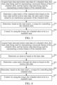
- FIG. 3 is a flowchart of a motion state control method according to an exemplary embodiment of this application. The method may be implemented in the microprocessor of the wheeled robot. As shown in FIG. 3 , in the above second time period, the control of the wheeled robot to switch from the initial motion state to the standstill state includes the following steps:
- Step 301 Acquire basic data and motion state data of the wheeled robot, the basic data being used for representing a structural feature of the wheeled robot, and the motion state data being used for representing a motion feature of the wheeled robot.
- the basic data of the wheeled robot and real-time motion state data of the wheeled robot are acquired.
- the basic data is used for representing the structural feature of the wheeled robot.
- the structural feature includes physical values of a plurality of parts of the robot. Taking the wheeled biped robot 100 in FIG. 1 as an example, the structural feature includes a height of a current leg structure, a mass of the body portion, a mass of the wheel, a radius of the wheel, a distance between two wheels, and the like.
- the structural feature may further include a linkage structure among the parts.
- the linkage structure may also be embodied in the basic data. This application does not limit a specific form or content of the basic data.
- some basic data may be preset.
- the fixed basic data may include first mass data of the body portion, second mass data of the wheel in the wheel leg portion, and a correspondence between the angle of the leg structure and the height.
- a part of the basic data may be obtained by calculation.
- the height in the basic data may be calculated according to the angle of the leg structure and the correspondence.
- the angle of the leg structure is an angle between the calf segment and the thigh segment of the leg structure.
- the motion state data is used for representing the motion feature of the wheeled robot, and may include tilt angle data of the wheeled robot and rotation data of the wheel, such as the tilt angle, the tilt rate, the rotation distance of the wheel (that is, a movement distance of the wheeled robot), and the rotational linear velocity of the wheel.
- This application does not limit a specific form or content of the motion state data.
- the motion state data is detected according to the motion state of the wheeled robot.
- the tilt angle data of the wheeled robot may be collected and acquired by a sensor, and the data related to the wheel may be read by the motor. This application does not limit a specific manner of acquiring the motion state data.
- Step 302 Determine a state matrix of the wheeled robot based on the basic data and the motion state data, the state matrix being related to an interference parameter of the wheeled robot.
- the state matrix is a representation of a dynamic equation of the wheeled robot, which may be determined by using the basic data and the motion state data.
- the interference parameter corresponds to the balance error of the wheeled robot.
- the balance error is an error between an actual center of gravity and a predicted or calibrated center of gravity.
- the wheeled robot has an assembly error, or a mounting pose of an inertial measurement unit (IMU) has an error, or due to other various reasons, the actual center of gravity is inconsistent with the designed or calibrated center of gravity. Therefore, in this embodiment, the state matrix embodying the interference parameter is predicted, which can facilitate more effective balance control of the wheeled robot.
- the state matrix may be represented as a set of simultaneous dynamic equations.
- an actual interference parameter value may be obtained directly based on the basic data and the motion state data, and then the state matrix is determined according to the basic data, the motion state data, and the interference parameter.
- the basic data and the motion state data may be combined to determine the state matrix of the wheeled robot, and the interference parameter is embodied in the state matrix.
- the interference parameter is related to the motion state data and the basic data.
- Step 303 Determine, based on the state matrix, a torque for controlling the wheeled robot.
- the torque for controlling the wheeled robot is obtained based on the state matrix.
- the torque is calculated based on an objective of controlling the wheeled robot to be in the standstill state.
- the torque is calculated according to linear output regulation.
- linear output regulation The following discloses an exemplary specific implementation with reference to FIG. 4 , but this application does not limit a specific method for determining the control torque.
- Step 304 Control, by using the torque, the wheeled robot to be in the standstill state.
- the calculated torque is transmitted to the motor, and the motor electrically controls the wheel of the wheeled robot, and controls the wheel to rotate by using the torque as a target, thereby driving the wheel structure of the wheeled robot and the body portion of the wheeled robot to be in the standstill state gradually.
- This application does not limit the implementation of applying the torque.
- a hydraulic-based driving manner is also included in this application.
- the state matrix that embodies the balance error of the robot is first determined, so as to determine, based on the state matrix, the torque for controlling the wheeled robot is determined, and the wheel of the wheeled robot is controlled by using the torque, so as to control the wheeled robot to be in the standstill state, thereby improving the accuracy of controlling the wheeled robot having the balance error.
- FIG. 4 is a flowchart of a motion state control method according to some embodiments of this application.
- the estimation of the state matrix embodying the interference parameter is implemented by the observer, for example.
- the method includes the following steps:
- Step 401 Acquire basic data and motion state data, the basic data being used for representing a structural feature of a wheeled robot, and the motion state data being used for representing a motion feature of the wheeled robot.
- step 301 For an implementation of this step, refer to step 301, which is omitted herein.
- Step 402 Determine an observer based on the basic data.
- the observer may be an equation that can be used to iteratively update a state matrix estimated by the observer by observing a physical quantity, so as to finally determine the state matrix.
- a form of the observer is designed before the observer is determined based on the basic data.
- the form of the observer may be determined according to a form of the state matrix of the wheeled robot.
- the form of the state matrix is given below by taking the wheeled biped robot 100 in FIG. 1 as an example. It is to be understood that the state matrix of other wheeled robots may have different forms, and the state matrix of the wheeled biped robot 100 may be in an approximate form or represented in other forms, which are all within the disclosure scope of this application.
- a matrix parameter in the observer is determined based on the basic data, and the observer for determining the state matrix is acquired according to the matrix parameter.
- a maximum value of the pitch angle is a desired value that matches a mathematical model.
- ⁇ represents a corrected value of the pitch angle
- ⁇ represents a measured or theoretical pitch angle
- d represents the interference parameter in the embodiments of this application, which is a constant.
- an iteration value in the observer is selected according to a meaning of the physical quantity.
- An actual value of the iteration value may be measured, or may be calculated according to the measured physical quantity. Therefore, a form of the iteration value may be selected depending on the physical quantity that can be measured, or depending on the form or the content of the motion state data. Exemplarily, the form of the iteration value in the observer is determined based on the content of the motion state data.
- the iteration value of the observer may be selected from the following physical quantities: the tilt angle of the wheeled robot, the tilt rate, the rotation distance of the wheel, and the rotational linear velocity of the wheel.
- the form of the observer is described below by using the wheeled biped robot 100 as an example. It is to be understood that the observer may have a plurality of implementations for state matrices having different forms. This application does not limit a specific selection of the form of the observer.
- the matrix parameters ⁇ and B ⁇ in the observer may be determined according to the basic data such as M, m, l, and g.
- the matrix parameter ⁇ is known.
- y m is an actual value of the iteration value
- ⁇ is an estimated value of the iteration value.
- L may be a preset parameter, indicating a magnitude by which the observer performs iterative updating according to a difference between the actual value and the estimated value of the iteration value.
- this embodiment exemplarily discloses how to determine the observer based on the basic data.
- Step 403 Determine the state matrix through the observer based on the motion state data.
- the state matrix including the interference parameter is determined through the observer based on the motion state data.
- the state matrix estimated by the observer is iteratively updated according to the observed motion state data, to finally determine the state matrix.
- the state matrix is first estimated by the observer, so as to determine the estimated value of the iteration value according to the state matrix estimated by the observer and determine the actual value of the iteration value according to the motion state data, the difference between the estimated value and the actual value of the iteration value is acquired, and the estimated state matrix is updated through the observer according to the difference.
- the process is repeated a plurality of times to iteratively update the state matrix estimated by the observer, so as to continuously approximate the state matrix, thereby finally determining the state matrix.
- a quantity of times of the iterative updating of the state matrix is preset.
- the quantity of times of the iterative updating of the state matrix is determined according to the difference between the estimated value and the actual value of the iteration value.
- the estimated state matrix ⁇ in the equation VI of the observer is iteratively updated according to the iteration value difference (y m - ⁇ ), to finally determine the state matrix ⁇ .
- ⁇ includes the estimated ⁇ ⁇ ⁇ , ⁇ ⁇ ⁇ , x ⁇ , x ⁇ ⁇ and the interference parameter d ⁇ . Since the iterative updating manner can continuously adapt to a new state matrix, in this embodiment, the state matrix with the interference parameter being changed during the motion can be determined. For example, the height of the wheeled biped robot is changed during the motion, which causes the balance point and the state matrix to change. Even so, the observer can still adjust the determined changed state matrix according to the motion state data with the state being changed.
- this embodiment exemplarily discloses how to determine the state matrix including interference parameter through the observer based on the motion state data.
- Step 404 Determine, based on the state matrix, a torque for controlling the wheeled robot.
- a control operation to be performed on the robot may be determined according to the state matrix obtained by the observer, such as applying the control torque.
- a target state of the system that is, a target output of the dynamic system is ⁇ approximating zero and ⁇ approximating zero.
- An input of the system is determined according to the target output of the system.
- an input matrix for controlling the wheeled robot is determined, and a product of the input matrix and the state matrix is determined as the torque for controlling the wheeled robot.
- k x and k d are elements in the input matrix.
- k x is a gain matrix, and k d is a gain coefficient.
- C 0 1 0 0 0 0 0 1 .
- a product of the input matrix K and the above state matrix ⁇ is inputted to the motor as the torque u.
- the embodiment discloses the method for determining, based on the state matrix, the torque for controlling the wheeled robot, but this application does not limit the specific method for determining the torque for controlling the wheeled robot.
- Step 405 Control, by using the torque, the wheeled robot to be in the standstill state.
- the wheel of the wheeled robot is controlled based on the torque, and the wheeled robot is stabilized in the standstill state.
- This application does not limit a specific implementation of controlling, by using the torque, the wheeled robot to be in the standstill state.
- the state matrix of the wheeled robot in a current state is determined through the observer, the state matrix including the balance error (the interference parameter), so as to determine, based on the state matrix, the torque for controlling the wheeled robot, and the wheel of the wheeled robot is controlled by using the torque, so as to control the wheeled robot to be in the standstill state, thereby improving the accuracy of controlling the wheeled robot having the balance error.
- the balance error the interference parameter
- Robot/IPC in the second row represents the basic data of the wheeled biped robot 100.
- m represents that the mass of the body portion is 11 kg
- M represents that the mass of the wheel is 3 kg
- g represents that the acceleration of gravity is 9.81 m/s 2
- 1 is the height, which is adjustable between 0.37 meters and 0.7 meters (that is, the distance from the motor of the body portion to the ground at different use angles)
- r w represents the radius of the wheel
- d w represents the distance between the two wheels.
- Output regulation in the third row represents the parameters used in the linear output regulation method obtained in the embodiments of this application, including but not limited to the gain matrix k x , the gain parameter k d , and the matrix L in the input matrix.
- the pitch angle ⁇ , a roll angle ⁇ , and rates of the pitch angle ⁇ and the roll angle ⁇ are measured through the IMU according to the above parameters.
- an angular velocity ⁇ r (rad/s) of a right wheel and an angular velocity ⁇ l (rad/s) of a left wheel are read through a motor coder.
- a linear velocity ⁇ and a yaw rate ⁇ of the wheeled biped robot 100 in an x direction are calculated, which is shown as the following equation IX:
- ⁇ 0.5 r w u .
- ⁇ is an average torque of the left and right motors.
- ⁇ ⁇ is a relative yaw rate provided by a remote controller. Since a sum of the yaw torques does not change a total torque in the x direction, the balance of the robot is not destroyed.
- a central processing unit with a model PICO-WHU4 is used.
- x k represents a distance at a moment k
- x k -1 represents a distance at a moment k-1
- ⁇ k -1 represents a velocity at the moment k-1.
- the linear output regulation method provided in the embodiments of this application is described by using an experimental result of controlling the wheeled biped robot 100 to be in the standstill state as an example.
- FIG. 5 shows a state of the wheeled biped robot 520 during the experiment. That is, the wheeled biped robot 520 is controlled to be in the standstill state with the height remaining unchanged.
- linear output regulation with an observer is used to keep the robot stationary at a minimum height pose.
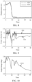
- FIG. 6 to FIG. 10 show a comparison between a physical quantity estimated by the observer with an actual observed value.
- FIG. 6 is a graph showing a comparison between an estimated value of the pitch angle estimated by the observer and an actual value of the pitch angle, with time being an abscissa.
- the estimated value of the pitch angle estimated by the observer is shown by a curve 620
- the actual value of the pitch angle is shown by a curve 630.
- the value of the pitch angle when the wheeled biped robot 520 is finally balanced is shown by a curve 610.
- FIG. 7 is a graph showing a comparison between an estimated value of the pitch rate estimated by the observer and an actual value of the pitch rate, with time being an abscissa. As shown in FIG. 7 , during the state adjustment of the wheeled biped robot 520, the estimated value of the pitch rate estimated by the observer is shown by a curve 710, and the actual value of the pitch rate is shown by a curve 720.
- FIG. 8 is a graph showing a comparison between an estimated value of the displacement estimated by the observer and an actual value of the displacement, with time being an abscissa. As shown in FIG. 8 , during the state adjustment of the wheeled biped robot 520, the estimated value of the displacement estimated by the observer is shown by a curve 810, and the actual value of the displacement is shown by a curve 820.
- FIG. 9 is a graph showing a comparison between an estimated value of the linear velocity estimated by the observer and an actual value of the linear velocity, with time being an abscissa. As shown in FIG. 9 , during the state adjustment of the wheeled biped robot 520, the estimated value of the linear velocity estimated by the observer is shown by a curve 910, and the actual value of the linear velocity is shown by a curve 920.
- FIG. 10 is a graph showing a change of a difference between the estimated value of the pitch rate observed by the observer and the actual value of the pitch rate, with time being an abscissa. As shown in FIG. 10 , during the state adjustment of the wheeled biped robot 520, a change of difference is shown by a curve 1010.
- the state matrix of the wheeled robot is determined, the state matrix embodying the interference parameter of the wheeled robot, so as to determine, based on the state matrix, the torque for controlling the wheeled robot, and the wheel of the wheeled robot is controlled by using the torque, so as to control the wheeled robot to be in the standstill state, thereby improving the accuracy of controlling the wheeled robot.
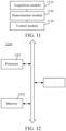
- FIG. 11 is a structural block diagram of a motion state control apparatus according to an exemplary embodiment of this application. As shown in FIG. 11 , the apparatus includes:
- the state matrix of the wheeled robot is determined, the state matrix embodying the interference parameter of the wheeled robot, so as to determine, based on the state matrix, the torque for controlling the wheeled robot, and the wheel of the wheeled robot is controlled by using the torque, so as to control the wheeled robot to be in the standstill state, thereby improving the accuracy of controlling the wheeled robot.
- the motion state control apparatus provided in the above embodiments is merely exemplified through division of the above functional modules.
- the above functions may be allocated to and completed by different functional modules as required. That is to say, the internal structure of the device is divided into different functional modules, to implement all or some of the functions described above.
- the motion state control apparatus provided in the above embodiments belongs to a same concept as the embodiments of the motion state control method. For the specific implementation, refer to the method embodiments, and the details are not described herein again.
- FIG. 12 is a structural block diagram of an electronic device 1200 according to an exemplary embodiment of this application.
- the electronic device 1200 may be a portable mobile terminal, such as: a smartphone, a tablet computer, a moving picture experts group audio layer III (MP3) player, a moving picture experts group audio layer IV (MP4) player, a notebook computer, or a desktop computer.
- MP3 moving picture experts group audio layer III
- MP4 moving picture experts group audio layer IV
- the electronic device 1200 may also be referred to as another name such as user equipment, a portable terminal, a laptop terminal, or a desktop terminal.
- the electronic device 1200 is implemented as a control device of the wheeled robot.
- the electronic device 1200 usually includes a processor 1201 and a memory 1202.
- the processor 1201 may include one or more processing cores, such as a 4-core processor or an 8-core processor.
- the processor 1201 may be implemented by at least one hardware form in a digital signal processing (DSP), a field-programmable gate array (FPGA), and a programmable logic array (PLA).
- DSP digital signal processing
- FPGA field-programmable gate array
- PDA programmable logic array
- the processor 1201 includes a main processor and a coprocessor.
- the main processor is configured to process data in an active state, also referred to as a central processing unit (CPU).
- the coprocessor is a low-power consumption processor configured to process data in a standby state.
- the processor 1201 may be integrated with a graphics processing unit (GPU).
- the GPU is configured to render and draw content that needs to be displayed on a display.
- the processor 1201 may further include an artificial intelligence (AI) processor.
- the AI processor is configured to process computing operations related to machine learning.
- the memory 1202 may include one or more computer-readable storage media.
- the computer-readable storage media may be non-transitory.
- the memory 1202 may further include a high-speed random access memory, as well as non-volatile memory, such as one or more disk storage devices and flash storage devices.
- the non-transitory computer-readable storage medium in the memory 1202 is configured to store at least one instruction, and the at least one instruction being configured to be executed by the processor 1201 to implement the motion state control method provided in the method embodiments of this application.
- the electronic device 1200 further optionally include other assemblies.
- a person skilled in the art may understand that the structure shown in FIG. 12 does not constitute a limitation to the electronic device 1200, and the electronic device may include more components or fewer components than those shown in the figure, or some components may be combined, or a different component deployment may be used.
- the embodiments of this application further provide a wheeled robot.
- the wheeled robot includes processor and a memory.
- the memory stores at least one instruction, at least one program, a code set, or an instruction set.
- the at least one instruction, the at least one program, the code set, or the instruction set is loaded and executed by the processor to implement the motion state control method according to the foregoing method embodiments.
- An embodiment of this application further provides a computer-readable storage medium storing at least one instruction, at least one segment of program, a code set or an instruction set, the at least one instruction, the at least one segment of program, the code set or the instruction set being loaded and executed by the processor to implement the motion state control method provided in the foregoing method embodiments.
- a computer program product or a computer program is further provided, the computer program product or the computer program including computer instructions, the computer instructions being stored in a computer-readable storage medium.
- a processor of a computer device reads the computer instructions from the computer-readable storage medium and executes the computer instructions to cause the computer device to perform the motion state control method described in any one of the foregoing embodiments.
Landscapes
- Engineering & Computer Science (AREA)
- Physics & Mathematics (AREA)
- Radar, Positioning & Navigation (AREA)
- Remote Sensing (AREA)
- Aviation & Aerospace Engineering (AREA)
- General Physics & Mathematics (AREA)
- Automation & Control Theory (AREA)
- Mechanical Engineering (AREA)
- Robotics (AREA)
- Chemical & Material Sciences (AREA)
- Combustion & Propulsion (AREA)
- Transportation (AREA)
- Electromagnetism (AREA)
- Computer Vision & Pattern Recognition (AREA)
- Human Computer Interaction (AREA)
- Acoustics & Sound (AREA)
- Multimedia (AREA)
- Control Of Position, Course, Altitude, Or Attitude Of Moving Bodies (AREA)
- Manipulator (AREA)
- Feedback Control In General (AREA)
- Motorcycle And Bicycle Frame (AREA)
Abstract
Description
- This application claims priority to
Chinese Patent Application No. 202110049662.8, entitled "MOTION STATE CONTROL METHOD AND APPARATUS, DEVICE, AND READABLE STORAGE MEDIUM", and filed on January 14, 2021 - Embodiments of this application relate to the field of robot control, and in particular, to a motion state control method and apparatus, a device, and a readable storage medium.
- A wheeled robot is a robot structure that controls motion of a robot body through a wheel structure. Since a contact point between the wheeled robot and the ground includes only a contact point between a wheel and the ground, a problem regarding balance control occurs in a case that the wheel structure is not stably arranged. In the related art, a conventional linear model is usually used for control.
- However, the related art does not take into account a physical difference between an actual wheeled robot and a desired model. Due to a mounting error or a difference between the similar models, an actual balance point may be different from a balance point in the desired model, resulting in an error in a wheel rotation torque required for balance control. Therefore, the above manner cannot realize stable balance control of the wheeled robot and has poor stability.
- Embodiments of this application provide a motion state control method and apparatus, a device, and a readable storage medium, which can improve the stability and the accuracy of controlling a wheeled robot. The technical solutions are as follows:
- An aspect provides a motion state control method applicable to a wheeled robot. The method includes:
- controlling the wheeled robot to be in an initial motion state, the initial motion state being a motion state of the wheeled robot in a first time period; and
- controlling the wheeled robot to switch from the initial motion state to a standstill state, such that the wheeled robot remains in the standstill state in a second time period through continuous adjustment in response to a balance error.
- Another aspect provides a control apparatus for controlling a motion state of a wheeled robot. The apparatus includes:
- a control module, configured to control the wheeled robot to be in an initial motion state, the initial motion state being a motion state of the wheeled robot in a first time period,
- the control module being further configured to control the wheeled robot to switch from the initial motion state to a standstill state, such that the wheeled robot remains in the standstill state in a second time period through continuous adjustment in response to a balance error.
- Another aspect provides a wheeled robot. The wheeled robot includes a processor and a memory storing at least one program, the at least one program being loaded and executed by the processor to implement the motion state control method according to any one of the above embodiments of this application.
- According to another aspect, a computer-readable storage medium is provided, storing at least one instruction, at least one segment of program, a code set, or an instruction set, the at least one instruction, the at least one segment of program, the code set or the instruction set being loaded and executed by a processor to implement the motion state control method according to any one of the foregoing embodiments of this application.
- According to another aspect, a computer program product or a computer program is provided, the computer program product or the computer program including computer instructions, the computer instructions being stored in a computer-readable storage medium. A processor of a computer device reads the computer instructions from the computer-readable storage medium and executes the computer instructions to cause the computer device to perform the motion state control method described in any one of the foregoing embodiments.
- The technical solutions provided in the embodiments of this application include at least the following beneficial effects:
- Before the torque for controlling the wheeled robot is determined, the state matrix that embodies the balance error of the robot is first determined, so as to determine, based on the state matrix, the torque for controlling the wheeled robot, and the wheel of the wheeled robot is controlled by using the torque, so as to control the wheeled robot to be in the standstill state, thereby improving the accuracy of controlling the wheeled robot having the balance error.
-
-
FIG. 1 is a schematic structural diagram of a wheeled robot according to an exemplary embodiment of this application. -
FIG. 2 is a schematic diagram showing a wheeled robot at a different height according to an exemplary embodiment of this application. -
FIG. 3 is a flowchart of a motion state control method according to an exemplary embodiment of this application. -
FIG. 4 is a flowchart of a motion state control method according to another exemplary embodiment of this application. -
FIG. 5 is a schematic diagram showing a wheeled robot in an experimental process according to an exemplary embodiment of this application. -
FIG. 6 is a graph showing a comparison between a measured state and an observed value of a pitch angle over time according to an exemplary embodiment of this application. -
FIG. 7 is a graph showing a comparison between an estimated value and an actual value of a pitch rate over time according to an exemplary embodiment of this application. -
FIG. 8 is a graph showing a comparison between an estimated value and an actual value of a displacement over time according to an exemplary embodiment of this application. -
FIG. 9 is a graph showing a comparison between an estimated value and an actual value of a linear velocity over time according to an exemplary embodiment of this application. -
FIG. 10 is a graph of an error value of a pitch angle over time according to an exemplary embodiment of this application. -
FIG. 11 is a structural block diagram of a motion state control apparatus according to an exemplary embodiment of this application. -
FIG. 12 is a structural block diagram of a terminal according to an exemplary embodiment of this application. - First, terms involved in the embodiments of this application are introduced as follows:
Wheeled robot: which is a robot structure that controls motion of a robot body through a wheel structure. Since a contact point between the wheeled robot and the ground includes only a contact point between a wheel and the ground, a problem regarding balance control occurs in a case that the wheel structure is not stably arranged. In some embodiments, the wheeled robot further includes a wheel-legged robot or a robot including a fixed wheel. The wheel-legged robot is a robot structure in which the wheel is fixed to a wheel leg and the wheel leg is foldable to adjust a height of the wheeled robot. The robot including a fixed wheel is a robot structure in which the wheel is fixed to a specified position of a robot body and a height of the robot is unadjustable. In this embodiment, the wheel-legged robot is used as an example for description. - Observer: The observer is a mathematical tool that can modify, according to an error between an estimated iteration value and an actual iteration value through iterative updating, a target mathematical relationship estimated by the observer, so as to finally obtain a relatively accurate target mathematical relationship. In the field of dynamics, the observer may iteratively update, by observing a physical quantity, a dynamic relationship estimated by the observer, so as to finally determine a relatively accurate dynamic relationship.
- In the embodiments of this application, the wheeled robot is implemented as a wheeled biped robot, for example. That is to say, the wheeled biped robot includes two wheels configured to move. The two wheels are respectively connected to a leg structure, and are connected to a robot body by the leg structure, so that the two wheels drive the robot body to complete motion control. However, it is to be understood that the wheeled robot in this application is not limited to the above structure. Any wheeled robot is to be understood as any robot that includes a wheeled structure.
- Exemplarily,
FIG. 1 is a schematic structural diagram of a wheeled robot according to an exemplary embodiment of this application. As shown inFIG. 1 , awheeled robot 100 includes abody portion 110 and awheel leg portion 120. - The
body portion 110 is connected to thewheel leg portion 120. Thewheel leg portion 120 includes twowheels 121 andleg structures 122, and theleg structures 122 are configured to connect thewheels 121 to thebody portion 110. As shown inFIG. 1 , thewheeled robot 100 includes a total of fourleg structures 122, and two of the fourleg structures 122 are respectively connected to one of thewheels 121. Exemplarily, a leg structure A, a leg structure B, a leg structure C, and a leg structure D are arranged. The leg structure A and the leg structure B are connected to a first one of the wheels, and the leg structure C and the leg structure D are connected to a second one of the wheels. A structure of two parallel leg planes of the wheeled robot is formed by the leg structure A, the leg structure B and the first wheel and by the leg structure C, the leg structure D, and the second wheel. The legs connected in parallel has five rotating joints each having two translational degrees of freedom in transverse and vertical directions. Compared with a series structure, the parallel structure has a compact structure, a high rigidity, and a strong bearing capacity. Therefore, the robot can jump higher and overcome obstacles nimbly. - Optionally, each of the
leg structures 122 includes acalf segment 1221 and athigh segment 1222. Thecalf segment 1221 and thethigh segment 1222 are connected by a rotating joint, and thecalf segment 1221 and thewheel 121 are also connected by a rotating joint. - Four motors respectively corresponding to the four
leg structures 122 are arranged in thebody portion 110. Eachleg structure 122 corresponds to a motor. The four motors are configured to control bending and unbending of theleg structure 122. In some embodiments, a segment of theleg structure 122 connected to thebody portion 110 is connected by the rotating joint. Exemplarily, as shown inFIG. 1 , when the motor drives the rotating joint to rotate clockwise, theleg structure 122 is controlled to gradually bend. When the motor drives the rotating joint to rotate counterclockwise, theleg structure 122 is controlled to gradually unbend (The twoleg structures 122 are driven by the rotating joints in the same way or different ways). That is to say, relationships between clockwise and counterclockwise rotation modes and bending and unbending control modes are the same or different. - The bending and unbending of the leg structure 122 (that is, a relative positional relationship between the
calf segment 1221 and the thigh segment 1222) is used for controlling a height of thewheeled robot 100. That is to say, the height of thewheeled robot 100 decreases when theleg structure 122 tends to bend, and the height of thewheeled robot 100 increases when theleg structure 122 tends to unbend. Theleg structure 122 shown inFIG. 1 is bent to a relatively large extent. In this case, thewheeled robot 100 is relatively low. Exemplarily, referring toFIG. 2 , a bending degree of theleg structure 122 is less than that of theleg structure 122 inFIG. 1 . At the bending degree, thewheeled robot 100 is relatively high. At the different heights inFIG. 1 and FIG. 2 , balancing performance of the wheeled robot also varies, and therefore balance control torques at the two heights are different. - The
wheel 121 is a driver, that is, thewheel 121 can realize active rotation after being driven by the motor, so as to realize motion state control of thewheeled robot 100. For example, the wheel controls the wheeled robot to move forward, control the wheeled robot to retreat, control the wheeled robot to turn, or control the wheeled robot to stand still. - Based on the structure including the
body portion 110 and thewheel leg portion 120 in thewheeled robot 100, thewheeled robot 100 may be approximated as a cart-inverted pendulum structure. The height of thewheeled robot 100 corresponds to a pendulum length of the inverted pendulum structure. - The
body portion 110 and thewheel 121 account for a majority of thewheeled robot 100 in weight. A weight factor of thebody portion 110 mainly includes four motors for driving theleg structure 122, a microcomputer, a circuit board, a motor, a battery, and the like. - A dynamic model of the
wheeled robot 100 may be expressed by the following equation I:
- m represents a mass of a cart body of the wheeled robot, that is, a mass of the body portion, M presents a mass of the wheel of the wheeled robot, 1 is a current height of the wheeled robot, that is, a height of the wheeled robot in a current leg structure, X represents a rotation distance of the wheel, ẋ represents a rotational linear velocity of the wheel, ẍ represents a rotational linear acceleration, θ represents a tilt angle of the wheeled robot, θ̇ represents a tilt rate of the wheeled robot, and θ̈ represents a tilt acceleration of the wheeled robot. In this embodiment, the tilt angle θ is the pitch angle of the wheeled robot, for example, u is thrust applied to the wheeled robot, and a correspondence exists between u and a torque applied to the wheel.
- Since only one contact point exists between the ground and the wheeled structure (that is, the contact point between the wheel and the ground), the wheeled robot has a problem regarding balance control when the plurality of wheeled structures are not stably arranged. Since a mass distribution of the robot changes, a balance point is usually away from a position predicted by an approximation model. Therefore, it is difficult to provide an accurate reference position for balance control. In this case, an output of the system may be regulated through output regulation to a desired state with unknown interference. In an embodiment of this application, an output regulation controller that can improve the balance control effect for the wheeled robot is provided.
- In this embodiment of this application, the wheeled robot is first controlled to be in an initial motion state, the initial motion state is a motion state of the wheeled robot in a first time period, so as to control the wheeled robot to switch from the initial motion state to a standstill state, such that the wheeled robot remains in the standstill state in a second time period through continuous adjustment in response to a balance error.
- In some embodiments, the initial motion state includes at least one of the following states: leaning still on the ground, constant speed movement, accelerated movement, or jumping. The first time period precedes the second time period in timing.
- In some embodiments, the wheeled robot is controlled, according to a received control instruction to switch to the standstill state at a start moment of the second time period. Alternatively, in some embodiments, the wheeled robot is controlled according to path planning data to switch to the standstill state at the start moment of the second time period. This is not limited in this embodiment.
- The control of the wheeled robot to switch from the initial motion state to the standstill state is performed according to basic data and motion state data of the wheeled robot'.
FIG. 3 is a flowchart of a motion state control method according to an exemplary embodiment of this application. The method may be implemented in the microprocessor of the wheeled robot. As shown inFIG. 3 , in the above second time period, the control of the wheeled robot to switch from the initial motion state to the standstill state includes the following steps: - Step 301: Acquire basic data and motion state data of the wheeled robot, the basic data being used for representing a structural feature of the wheeled robot, and the motion state data being used for representing a motion feature of the wheeled robot.
- Optionally, the basic data of the wheeled robot and real-time motion state data of the wheeled robot are acquired.
- The basic data is used for representing the structural feature of the wheeled robot. The structural feature includes physical values of a plurality of parts of the robot. Taking the wheeled
biped robot 100 inFIG. 1 as an example, the structural feature includes a height of a current leg structure, a mass of the body portion, a mass of the wheel, a radius of the wheel, a distance between two wheels, and the like. The structural feature may further include a linkage structure among the parts. For example, in the wheeledbiped robot 100 inFIG. 1 , the body portion and the leg structure move leftward relative to the wheel through linkage when the wheel is controlled to rotate clockwise so as to control the wheeled robot to move rightward. The linkage structure may also be embodied in the basic data. This application does not limit a specific form or content of the basic data. - In some embodiments, since the basic structure of the wheeled robot is partially fixed, some basic data may be preset. Taking the wheeled
biped robot 100 inFIG. 1 as an example, the fixed basic data may include first mass data of the body portion, second mass data of the wheel in the wheel leg portion, and a correspondence between the angle of the leg structure and the height. In some embodiments, a part of the basic data may be obtained by calculation. Taking the wheeledbiped robot 100 inFIG. 1 as an example, the height in the basic data may be calculated according to the angle of the leg structure and the correspondence. The angle of the leg structure is an angle between the calf segment and the thigh segment of the leg structure. - The motion state data is used for representing the motion feature of the wheeled robot, and may include tilt angle data of the wheeled robot and rotation data of the wheel, such as the tilt angle, the tilt rate, the rotation distance of the wheel (that is, a movement distance of the wheeled robot), and the rotational linear velocity of the wheel. This application does not limit a specific form or content of the motion state data.
- In some embodiments, the motion state data is detected according to the motion state of the wheeled robot. For example, the tilt angle data of the wheeled robot may be collected and acquired by a sensor, and the data related to the wheel may be read by the motor. This application does not limit a specific manner of acquiring the motion state data.
- Step 302: Determine a state matrix of the wheeled robot based on the basic data and the motion state data, the state matrix being related to an interference parameter of the wheeled robot.
- The state matrix is a representation of a dynamic equation of the wheeled robot, which may be determined by using the basic data and the motion state data. The interference parameter corresponds to the balance error of the wheeled robot. The balance error is an error between an actual center of gravity and a predicted or calibrated center of gravity. In some cases, the wheeled robot has an assembly error, or a mounting pose of an inertial measurement unit (IMU) has an error, or due to other various reasons, the actual center of gravity is inconsistent with the designed or calibrated center of gravity. Therefore, in this embodiment, the state matrix embodying the interference parameter is predicted, which can facilitate more effective balance control of the wheeled robot. It is to be understood by those skilled in the art that, in some embodiments, the state matrix may be represented as a set of simultaneous dynamic equations.
- In some embodiments, an actual interference parameter value may be obtained directly based on the basic data and the motion state data, and then the state matrix is determined according to the basic data, the motion state data, and the interference parameter.
- In other embodiments, the basic data and the motion state data may be combined to determine the state matrix of the wheeled robot, and the interference parameter is embodied in the state matrix. In some embodiments, the interference parameter is related to the motion state data and the basic data.
- The following discloses an exemplary specific implementation with reference to
FIG. 4 , but this application does not limit the specific implementation of determining the state matrix. - Step 303: Determine, based on the state matrix, a torque for controlling the wheeled robot.
- The torque for controlling the wheeled robot is obtained based on the state matrix. The torque is calculated based on an objective of controlling the wheeled robot to be in the standstill state.
- In some embodiments, the torque is calculated according to linear output regulation. The following discloses an exemplary specific implementation with reference to
FIG. 4 , but this application does not limit a specific method for determining the control torque. - Step 304: Control, by using the torque, the wheeled robot to be in the standstill state.
- In some embodiments, the calculated torque is transmitted to the motor, and the motor electrically controls the wheel of the wheeled robot, and controls the wheel to rotate by using the torque as a target, thereby driving the wheel structure of the wheeled robot and the body portion of the wheeled robot to be in the standstill state gradually. This application does not limit the implementation of applying the torque. For example, a hydraulic-based driving manner is also included in this application.
- Based on the above, according to the motion state control method provided in the embodiments of this application, before the torque for controlling the wheeled robot is determined, the state matrix that embodies the balance error of the robot is first determined, so as to determine, based on the state matrix, the torque for controlling the wheeled robot is determined, and the wheel of the wheeled robot is controlled by using the torque, so as to control the wheeled robot to be in the standstill state, thereby improving the accuracy of controlling the wheeled robot having the balance error.
-
FIG. 4 is a flowchart of a motion state control method according to some embodiments of this application. In the embodiment shown inFIG. 4 , the estimation of the state matrix embodying the interference parameter is implemented by the observer, for example. The method includes the following steps: - Step 401: Acquire basic data and motion state data, the basic data being used for representing a structural feature of a wheeled robot, and the motion state data being used for representing a motion feature of the wheeled robot.
- For an implementation of this step, refer to step 301, which is omitted herein.
- Step 402: Determine an observer based on the basic data.
- The observer may be an equation that can be used to iteratively update a state matrix estimated by the observer by observing a physical quantity, so as to finally determine the state matrix.
- In some embodiments, a form of the observer is designed before the observer is determined based on the basic data. The form of the observer may be determined according to a form of the state matrix of the wheeled robot.
- The form of the state matrix is given below by taking the wheeled
biped robot 100 inFIG. 1 as an example. It is to be understood that the state matrix of other wheeled robots may have different forms, and the state matrix of the wheeledbiped robot 100 may be in an approximate form or represented in other forms, which are all within the disclosure scope of this application. - In some embodiments, a matrix parameter in the observer is determined based on the basic data, and the observer for determining the state matrix is acquired according to the matrix parameter.
- The kinematic model equation I of the wheeled
biped robot 100 near the balance point may be ideally approximated as linear. Refer to the following equation II:
- ξ = [θ θ̇ x ẋ] T , A and B are matrix parameters


- In some embodiments, a maximum value of the pitch angle is a desired value that matches a mathematical model. However, in other embodiments, θ measured by the IMU may deviate from a true value due to the reasons described above. Therefore, due to the balance error of the wheeled biped robot, that is, an interference parameter, the measured pitch angle may be corrected according to the following equation:

- θ̃ represents a corrected value of the pitch angle, θ represents a measured or theoretical pitch angle, and d represents the interference parameter in the embodiments of this application, which is a constant.
- Based on the equation III, the equation II of the state matrix of the above wheeled biped robot may be transformed to the following equation IV:

- ξ̃ used for representing a state of a dynamical system, and u is the applied torque, that is, an input of the dynamic system, ξ̃ = [θ̃ θ̇ x ẋ] T,


- In some embodiments, an iteration value in the observer is selected according to a meaning of the physical quantity. An actual value of the iteration value may be measured, or may be calculated according to the measured physical quantity. Therefore, a form of the iteration value may be selected depending on the physical quantity that can be measured, or depending on the form or the content of the motion state data. Exemplarily, the form of the iteration value in the observer is determined based on the content of the motion state data. In some embodiments, the iteration value of the observer may be selected from the following physical quantities: the tilt angle of the wheeled robot, the tilt rate, the rotation distance of the wheel, and the rotational linear velocity of the wheel.
- For example, an iteration quantity ym in the observer may be defined as follows:

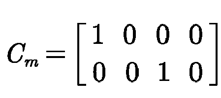
- Certainly, this application does not limit a specific selection of the iteration value. For example, in some embodiments, the iteration value may be selected as θ̇ and ẋ. That is to say, second and fourth terms in the above ξ̃ = [θ̃ θ̇ x ẋ] T are selected.
- The form of the observer is described below by using the wheeled
biped robot 100 as an example. It is to be understood that the observer may have a plurality of implementations for state matrices having different forms. This application does not limit a specific selection of the form of the observer. - In some embodiments, for the state matrix in the equation IV, the observer may use the following form:

- The state matrix estimated by the observer is


- Those skilled in the art understand that the observer in the form of the equation VI may be used to observe the state matrix in the form of the equation IV.
- The matrix parameters  and B̂ in the observer may be determined according to the basic data such as M, m, l, and g. The matrix parameter Ĉ is known. y m is an actual value of the iteration value, and Ĉξ̂, is an estimated value of the iteration value. L may be a preset parameter, indicating a magnitude by which the observer performs iterative updating according to a difference between the actual value and the estimated value of the iteration value.
- Therefore, this embodiment exemplarily discloses how to determine the observer based on the basic data.
- Step 403: Determine the state matrix through the observer based on the motion state data.
- The state matrix including the interference parameter is determined through the observer based on the motion state data. In some embodiments, the state matrix estimated by the observer is iteratively updated according to the observed motion state data, to finally determine the state matrix.
- In some embodiments, the state matrix is first estimated by the observer, so as to determine the estimated value of the iteration value according to the state matrix estimated by the observer and determine the actual value of the iteration value according to the motion state data, the difference between the estimated value and the actual value of the iteration value is acquired, and the estimated state matrix is updated through the observer according to the difference. In some embodiments, the process is repeated a plurality of times to iteratively update the state matrix estimated by the observer, so as to continuously approximate the state matrix, thereby finally determining the state matrix. A quantity of times of the iterative updating of the state matrix is preset. Alternatively, the quantity of times of the iterative updating of the state matrix is determined according to the difference between the estimated value and the actual value of the iteration value. In some embodiments, taking the wheeled biped robot as an example, the estimated state matrix ξ̂ in the equation VI of the observer is iteratively updated according to the iteration value difference (ym - Ĉξ̂), to finally determine the state matrix ζ̂. ζ̂ includes the estimated


- Thus, this embodiment exemplarily discloses how to determine the state matrix including interference parameter through the observer based on the motion state data.
- Step 404: Determine, based on the state matrix, a torque for controlling the wheeled robot.
- A control operation to be performed on the robot may be determined according to the state matrix obtained by the observer, such as applying the control torque. When the objective is to maintain the wheeled robot in standstill balance, a target state of the system, that is, a target output of the dynamic system is θ̇ approximating zero and ẋ approximating zero. An input of the system is determined according to the target output of the system.
- In an embodiment, an input matrix for controlling the wheeled robot is determined, and a product of the input matrix and the state matrix is determined as the torque for controlling the wheeled robot.
- Taking the wheeled biped robot as an example, θ̇ and ẋ can approximate zero only when an input matrix K = [kx kd ] and a specific vector Xc exist. kx and kd are elements in the input matrix. kx is a gain matrix, and kd is a gain coefficient. Exemplarily, the input matrix K may be calculated based on the following equations VII and VIII.


- The equation VII and the equation VIII are combined into an equation set, so as to calculate the input matrix K.
- A product of the input matrix K and the above state matrix ζ̂ is inputted to the motor as the torque u.
- Therefore, the embodiment discloses the method for determining, based on the state matrix, the torque for controlling the wheeled robot, but this application does not limit the specific method for determining the torque for controlling the wheeled robot.
- Step 405: Control, by using the torque, the wheeled robot to be in the standstill state.
- In some embodiments, the wheel of the wheeled robot is controlled based on the torque, and the wheeled robot is stabilized in the standstill state. This application does not limit a specific implementation of controlling, by using the torque, the wheeled robot to be in the standstill state.
- Based on the above, according to the motion state control method provided in the embodiments of this application, before the torque for controlling the wheeled robot is determined, the state matrix of the wheeled robot in a current state is determined through the observer, the state matrix including the balance error (the interference parameter), so as to determine, based on the state matrix, the torque for controlling the wheeled robot, and the wheel of the wheeled robot is controlled by using the torque, so as to control the wheeled robot to be in the standstill state, thereby improving the accuracy of controlling the wheeled robot having the balance error.
- Exemplarily, this application is applied to the embodiment of the wheeled
biped robot 100. The wheeled robot is controlled through linear output regulation, and the stability and performance of the linear output regulation are verified through experiments. First, parameters are summarized in Table 1.Table 1 Parameters Robot/IPC m = 11kg. M = 3kg; g = 9.81m/s 2; 0.37m≤l≤0.7m; rw = 0.1m ; dw = 0.47m Output regulation kx = [150 12 0.001 10]; kd = -167; 
- Robot/IPC in the second row represents the basic data of the wheeled
biped robot 100. For example, m represents that the mass of the body portion is 11 kg; M represents that the mass of the wheel is 3 kg; g represents that the acceleration of gravity is 9.81 m/s2; 1 is the height, which is adjustable between 0.37 meters and 0.7 meters (that is, the distance from the motor of the body portion to the ground at different use angles); and rw represents the radius of the wheel, and dw represents the distance between the two wheels. - Output regulation in the third row represents the parameters used in the linear output regulation method obtained in the embodiments of this application, including but not limited to the gain matrix kx, the gain parameter kd, and the matrix L in the input matrix.
- The pitch angle θ, a roll angle φ, and rates of the pitch angle θ and the roll angle φ are measured through the IMU according to the above parameters. In addition, an angular velocity ωr (rad/s) of a right wheel and an angular velocity ωl (rad/s) of a left wheel are read through a motor coder. Then, a linear velocity ẋ and a yaw rate γ̇ of the wheeled
biped robot 100 in an x direction are calculated, which is shown as the following equation IX:
- During control of the wheeled
biped robot 100 based on a balance force u, the balance force is converted to a torque through an equation τ = 0.5rwu. τ is an average torque of the left and right motors. The average torque τ plus the yaw torque τγ = 0.3 (γ̇ - γ̇ ∗) is used as a torque applied to the left motor, and the average torque τ and the yaw torque τγ = 0.3 (γ̇ - γ̇ ∗) is used as a torque applied to the right motor, thereby rotating the wheeled • *biped robot 100. γ̇ ∗ is a relative yaw rate provided by a remote controller. Since a sum of the yaw torques does not change a total torque in the x direction, the balance of the robot is not destroyed. - During the experiment, a central processing unit (CPU) with a model PICO-WHU4 is used. A processing cycle of the CPU is Ts ≈ 0.002s , and the CPU calculates x through xk = x k-1 + Tsẋ k-1 , and discretizes the observer. xk represents a distance at a moment k, x k-1 represents a distance at a moment k-1, and ẋ k-1 represents a velocity at the moment k-1.
- Exemplarily, the linear output regulation method provided in the embodiments of this application is described by using an experimental result of controlling the wheeled
biped robot 100 to be in the standstill state as an example. -
FIG. 5 shows a state of the wheeledbiped robot 520 during the experiment. That is, the wheeledbiped robot 520 is controlled to be in the standstill state with the height remaining unchanged. - In some embodiments, linear output regulation with an observer is used to keep the robot stationary at a minimum height pose.
FIG. 6 to FIG. 10 show a comparison between a physical quantity estimated by the observer with an actual observed value. -
FIG. 6 is a graph showing a comparison between an estimated value of the pitch angle estimated by the observer and an actual value of the pitch angle, with time being an abscissa. As shown inFIG. 6 , during the state adjustment of the wheeledbiped robot 520, the estimated value of the pitch angle estimated by the observer is shown by acurve 620, and the actual value of the pitch angle is shown by acurve 630. The value of the pitch angle when the wheeledbiped robot 520 is finally balanced is shown by acurve 610. -
FIG. 7 is a graph showing a comparison between an estimated value of the pitch rate estimated by the observer and an actual value of the pitch rate, with time being an abscissa. As shown inFIG. 7 , during the state adjustment of the wheeledbiped robot 520, the estimated value of the pitch rate estimated by the observer is shown by acurve 710, and the actual value of the pitch rate is shown by acurve 720. -
FIG. 8 is a graph showing a comparison between an estimated value of the displacement estimated by the observer and an actual value of the displacement, with time being an abscissa. As shown inFIG. 8 , during the state adjustment of the wheeledbiped robot 520, the estimated value of the displacement estimated by the observer is shown by acurve 810, and the actual value of the displacement is shown by acurve 820. -
FIG. 9 is a graph showing a comparison between an estimated value of the linear velocity estimated by the observer and an actual value of the linear velocity, with time being an abscissa. As shown inFIG. 9 , during the state adjustment of the wheeledbiped robot 520, the estimated value of the linear velocity estimated by the observer is shown by acurve 910, and the actual value of the linear velocity is shown by acurve 920. -
FIG. 10 is a graph showing a change of a difference between the estimated value of the pitch rate observed by the observer and the actual value of the pitch rate, with time being an abscissa. As shown inFIG. 10 , during the state adjustment of the wheeledbiped robot 520, a change of difference is shown by acurve 1010. - It can be learned from
FIG. 6 to FIG. 10 that when the actual balance point is unknown, the estimated state matrix gradually approaches the actual state matrix, and the wheeledbiped robot 520 successfully reaches a still and balanced state. In the balanced state, the estimated state matrix is still different from the actual state matrix to some extent, which is caused by friction between the wheel and a carpet. However, it can be learned fromFIG. 10 that after the still and balanced state is realized, the linear output regulation further causes the estimated value to approximate the actual value. - Based on the above, according to the motion state control method provided in the embodiments of this application, before the torque for controlling the wheeled robot is determined, the state matrix of the wheeled robot is determined, the state matrix embodying the interference parameter of the wheeled robot, so as to determine, based on the state matrix, the torque for controlling the wheeled robot, and the wheel of the wheeled robot is controlled by using the torque, so as to control the wheeled robot to be in the standstill state, thereby improving the accuracy of controlling the wheeled robot.
-
FIG. 11 is a structural block diagram of a motion state control apparatus according to an exemplary embodiment of this application. As shown inFIG. 11 , the apparatus includes: - an
acquisition module 1110, configured to perform the embodiments instep 301 and step 401; - a
determination module 1120, configured to perform the embodiments instep 302,step 303,step 402,step 403, and step 404; and - a
control module 1130, configured to perform the embodiments instep 303 andstep 405. - Based on the above, according to the motion state control method provided in the embodiments of this application, before the torque for controlling the wheeled robot is determined, the state matrix of the wheeled robot is determined, the state matrix embodying the interference parameter of the wheeled robot, so as to determine, based on the state matrix, the torque for controlling the wheeled robot, and the wheel of the wheeled robot is controlled by using the torque, so as to control the wheeled robot to be in the standstill state, thereby improving the accuracy of controlling the wheeled robot.
- The motion state control apparatus provided in the above embodiments is merely exemplified through division of the above functional modules. In actual application, the above functions may be allocated to and completed by different functional modules as required. That is to say, the internal structure of the device is divided into different functional modules, to implement all or some of the functions described above. In addition, the motion state control apparatus provided in the above embodiments belongs to a same concept as the embodiments of the motion state control method. For the specific implementation, refer to the method embodiments, and the details are not described herein again.
-
FIG. 12 is a structural block diagram of anelectronic device 1200 according to an exemplary embodiment of this application. Theelectronic device 1200 may be a portable mobile terminal, such as: a smartphone, a tablet computer, a moving picture experts group audio layer III (MP3) player, a moving picture experts group audio layer IV (MP4) player, a notebook computer, or a desktop computer. Theelectronic device 1200 may also be referred to as another name such as user equipment, a portable terminal, a laptop terminal, or a desktop terminal. In this embodiment of this application, theelectronic device 1200 is implemented as a control device of the wheeled robot. - The
electronic device 1200 usually includes aprocessor 1201 and amemory 1202. - The
processor 1201 may include one or more processing cores, such as a 4-core processor or an 8-core processor. Theprocessor 1201 may be implemented by at least one hardware form in a digital signal processing (DSP), a field-programmable gate array (FPGA), and a programmable logic array (PLA). theprocessor 1201 includes a main processor and a coprocessor. The main processor is configured to process data in an active state, also referred to as a central processing unit (CPU). The coprocessor is a low-power consumption processor configured to process data in a standby state. In some embodiments, theprocessor 1201 may be integrated with a graphics processing unit (GPU). The GPU is configured to render and draw content that needs to be displayed on a display. In some embodiments, theprocessor 1201 may further include an artificial intelligence (AI) processor. The AI processor is configured to process computing operations related to machine learning. - The
memory 1202 may include one or more computer-readable storage media. The computer-readable storage media may be non-transitory. Thememory 1202 may further include a high-speed random access memory, as well as non-volatile memory, such as one or more disk storage devices and flash storage devices. In some embodiments, the non-transitory computer-readable storage medium in thememory 1202 is configured to store at least one instruction, and the at least one instruction being configured to be executed by theprocessor 1201 to implement the motion state control method provided in the method embodiments of this application. - In some embodiments, the
electronic device 1200 further optionally include other assemblies. A person skilled in the art may understand that the structure shown inFIG. 12 does not constitute a limitation to theelectronic device 1200, and the electronic device may include more components or fewer components than those shown in the figure, or some components may be combined, or a different component deployment may be used. - The embodiments of this application further provide a wheeled robot. The wheeled robot includes processor and a memory. The memory stores at least one instruction, at least one program, a code set, or an instruction set. The at least one instruction, the at least one program, the code set, or the instruction set is loaded and executed by the processor to implement the motion state control method according to the foregoing method embodiments.
- An embodiment of this application further provides a computer-readable storage medium storing at least one instruction, at least one segment of program, a code set or an instruction set, the at least one instruction, the at least one segment of program, the code set or the instruction set being loaded and executed by the processor to implement the motion state control method provided in the foregoing method embodiments.
- According to an aspect of the embodiments of this application, a computer program product or a computer program is further provided, the computer program product or the computer program including computer instructions, the computer instructions being stored in a computer-readable storage medium. A processor of a computer device reads the computer instructions from the computer-readable storage medium and executes the computer instructions to cause the computer device to perform the motion state control method described in any one of the foregoing embodiments.
Claims (28)
- A motion state control method, applicable to a wheeled robot, the method comprising:controlling the wheeled robot to be in an initial motion state, the initial motion state being a motion state of the wheeled robot in a first time period; andcontrolling the wheeled robot to switch from the initial motion state to a standstill state, such that the wheeled robot remains in the standstill state in a second time period through continuous adjustment in response to a balance error.
- The method according to claim 1, wherein the controlling the wheeled robot to switch from the initial motion state to a standstill state comprises:acquiring basic data and motion state data of the wheeled robot, the basic data being used for representing a structural feature of the wheeled robot, and the motion state data being used for representing a motion feature of the wheeled robot;determining a state matrix of the wheeled robot based on the basic data and the motion state data, the state matrix being related to an interference parameter of the wheeled robot, the interference parameter corresponding to the balance error of the wheeled robot;determining, based on the state matrix, a torque for controlling the wheeled robot; andcontrolling, by using the torque, the wheeled robot to be in the standstill state.
- The method according to claim 2, wherein the determining a state matrix of the wheeled robot based on the basic data and the motion state data comprises:determining an observer based on the basic data; anddetermining the state matrix through the observer based on the motion state data and the interference parameter.
- The method according to claim 3, wherein the determining an observer based on the basic data comprises:determining a matrix parameter in the observer based on the basic data; andobtaining, according to the matrix parameter, the observer for determining the state matrix.
- The method according to claim 3, wherein the determining the state matrix through the observer based on the motion state data comprises:estimating the state matrix through the observer;determining an estimated value of an iteration value according to the estimated state matrix;determining an actual value of the iteration value according to the motion state data;acquiring a difference between the estimated value and the actual value; andupdating the estimated state matrix through the observer according to the difference to obtain the state matrix.
- The method according to claim 5, further comprising:determining a form of the observer based on a form of the state matrix of the wheeled robot; anddetermining a form of the iteration value in the observer based on content of the motion state data.
- The method according to claim 5, wherein
a form of the observer is
- The method according to claim 7, wherein


- The method according to claim 5, further comprising:determining a changed state matrix of the wheeled robot based on changed basic data and the motion state data after the basic data of the wheeled robot changes; ordetermining a changed state matrix of the wheeled robot based on the basic data and changed motion state data after the motion state data of the wheeled robot changes; ordetermining a changed state matrix of the wheeled robot based on changed basic data and changed motion state data after the basic data and the motion state data of the wheeled robot change.
- The method according to claim 2, wherein the determining, based on the state matrix, a torque for controlling the wheeled robot comprises:determining an input matrix for controlling the wheeled robot, the input matrix being a matrix determined based on the basic data of the wheeled robot; anddetermining a product of the input matrix and the state matrix as the torque for controlling the wheeled robot.
- The method according to claim 10, wherein the determining an input matrix for controlling the wheeled robot comprises:determining an equation between a control torque and the state matrix in a case that a pitch rate and a linear velocity of the wheeled robot approximate zero; anddetermining the input matrix according to the equation.
- The method according to claim 10, wherein the input matrix K satisfies:


- The method according to any one of claims 1 to 12, wherein the wheeled robot comprises the body portion and a wheel leg portion, the wheel leg portion and the body portion being an inverted pendulum structure, and the height of the wheeled robot being adjusted through the wheel leg portion.
- A control apparatus for controlling a motion state of a wheeled robot, the apparatus comprising:a control module, configured to control the wheeled robot to be in an initial motion state, the initial motion state being a motion state of the wheeled robot in a first time period,the control module being further configured to control the wheeled robot to switch from the initial motion state to a standstill state, such that the wheeled robot remain in the standstill state in a second time period through continuous adjustment in response to a balance error.
- The apparatus according to claim 14, further comprising:an acquisition module, configured to acquire basic data and motion state data of the wheeled robot, the basic data being used for representing a structural feature of the wheeled robot, and the motion state data being used for representing a motion feature of the wheeled robot; anda determination module, configured to determine a state matrix of the wheeled robot based on the basic data and the motion state data, the state matrix being related to an interference parameter of the wheeled robot, the interference parameter corresponding to the balance error of the wheeled robot,the determination module being further configured to determine, based on the state matrix, a torque for controlling the wheeled robot; andthe control module being further configured to control, by using the torque, the wheeled robot to be in the standstill state.
- The apparatus according to claim 15, wherein the determination module is further configured to determine an observer based on the basic data; and determine the state matrix through the observer based on the motion state data and the interference parameter.
- The apparatus according to claim 16, wherein the determination module is further configured to determine a matrix parameter in the observer based on the basic data; and obtain, according to the matrix parameter, the observer for determining the state matrix.
- The apparatus according to claim 16, wherein the determination module is further configured to: estimate the state matrix through the observer; determine an estimated value of an iteration value according to the estimated state matrix; determine an actual value of the iteration value according to the motion state data; acquire a difference between the estimated value and the actual value; and update the estimated state matrix through the observer according to the difference to obtain the state matrix.
- The apparatus according to claim 18, wherein the determination module is further configured to determine a form of the observer based on a form of the state matrix of the wheeled robot; and determine a form of the iteration value in the observer based on content of the motion state data.
- The apparatus according to claim 18, wherein
a form of the observer is
- The apparatus according to claim 20, wherein

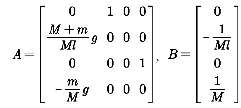

- The apparatus according to claim 18, wherein the determination module is further configured todetermine a changed state matrix of the wheeled robot based on changed basic data and the motion state data after the basic data of the wheeled robot changes; ordetermine a changed state matrix of the wheeled robot based on the basic data and changed motion state data after the motion state data of the wheeled robot changes; ordetermine a changed state matrix of the wheeled robot based on changed basic data and changed motion state data after the basic data and the motion state data of the wheeled robot change.
- The apparatus according to claim 15, wherein the determination module is further configured to determine an input matrix for controlling the wheeled robot, the input matrix being a matrix determined based on the basic data of the wheeled robot; and determine a product of the input matrix and the state matrix as the torque for controlling the wheeled robot.
- The apparatus according to claim 23, wherein the determination module is further configured to determine an equation between a control torque and the state matrix in a case that a pitch rate and a linear velocity of the wheeled robot approximate zero; and determine the input matrix according to the equation.
- The apparatus according to claim 23, wherein the input matrix K satisfies:


- The apparatus according to any one of claims 14 to 25, wherein the wheeled robot comprises the body portion and a wheel leg portion, the wheel leg portion and the body portion being an inverted pendulum structure, and the height of the wheeled robot being adjusted through the wheel leg portion.
- A wheeled robot, comprising a processor and a memory, the memory storing at least one program, the at least one program being loaded and executed by the processor to implement the motion state control method according to any one of claims 1 to 13.
- A computer-readable storage medium, storing at least one program, the at least one program being loaded and executed by a processor to implement the motion state control method according to any one of claims 1 to 13.
Applications Claiming Priority (2)
| Application Number | Priority Date | Filing Date | Title |
|---|---|---|---|
| CN202110049662.8A CN114764241B (en) | 2021-01-14 | 2021-01-14 | Motion state control method, device, equipment and readable storage medium |
| PCT/CN2022/071024 WO2022152083A1 (en) | 2021-01-14 | 2022-01-10 | Method and apparatus for controlling motion state, and device and readable storage medium |
Publications (3)
| Publication Number | Publication Date |
|---|---|
| EP4246271A1 true EP4246271A1 (en) | 2023-09-20 |
| EP4246271A4 EP4246271A4 (en) | 2024-03-27 |
| EP4246271B1 EP4246271B1 (en) | 2026-03-04 |
Family
ID=82363090
Family Applications (1)
| Application Number | Title | Priority Date | Filing Date |
|---|---|---|---|
| EP22738964.0A Active EP4246271B1 (en) | 2021-01-14 | 2022-01-10 | Method and apparatus for controlling motion state, and device and readable storage medium |
Country Status (5)
| Country | Link |
|---|---|
| US (2) | US12321180B2 (en) |
| EP (1) | EP4246271B1 (en) |
| JP (1) | JP7518975B2 (en) |
| CN (1) | CN114764241B (en) |
| WO (1) | WO2022152083A1 (en) |
Families Citing this family (8)
| Publication number | Priority date | Publication date | Assignee | Title |
|---|---|---|---|---|
| CN111776106B (en) * | 2020-08-12 | 2024-02-23 | 腾讯科技(深圳)有限公司 | Robotic legs and wheeled mobility devices |
| CN116991154B (en) | 2022-08-20 | 2025-07-01 | 腾讯科技(深圳)有限公司 | Motion control method of mobile robot and mobile robot |
| CN116991156B (en) * | 2022-09-30 | 2025-07-18 | 腾讯科技(深圳)有限公司 | Control method and device for two-wheeled robot, medium, program, and robot |
| CN115903874B (en) * | 2022-12-15 | 2025-10-14 | 深圳市优必选科技股份有限公司 | Robot balance control method, device, readable storage medium and robot |
| CN118832571B (en) * | 2023-04-25 | 2025-06-13 | 腾讯科技(深圳)有限公司 | Control method, device, equipment and storage medium of mobile robot |
| CN119024875B (en) * | 2023-07-14 | 2025-07-04 | 腾讯科技(深圳)有限公司 | Balance control method, device and equipment for wheel leg type robot and storage medium |
| CN118514083B (en) * | 2024-07-19 | 2024-11-15 | 湖南视比特机器人有限公司 | Multi-robot joint calibration method, system and computer equipment |
| CN121535741B (en) * | 2025-12-16 | 2026-07-31 | 北京理工大学 | Control method, device, equipment and storage medium of wheeled robot |
Family Cites Families (29)
| Publication number | Priority date | Publication date | Assignee | Title |
|---|---|---|---|---|
| JP2004299010A (en) | 2003-03-31 | 2004-10-28 | Fanuc Ltd | Deflection correction device and deflection correction method |
| KR100709556B1 (en) | 2005-10-19 | 2007-04-20 | 한국과학기술연구원 | Walking control method of humanoid robot |
| JP4797775B2 (en) * | 2006-04-24 | 2011-10-19 | 株式会社日立製作所 | Biped type moving mechanism |
| US8083013B2 (en) * | 2006-12-06 | 2011-12-27 | The Regents Of The University Of California | Multimodal agile robots |
| US8295951B2 (en) * | 2007-12-21 | 2012-10-23 | The University Of Florida Research Foundation, Inc. | Systems and methods for offset-free model predictive control |
| US8041456B1 (en) * | 2008-10-22 | 2011-10-18 | Anybots, Inc. | Self-balancing robot including an ultracapacitor power source |
| JP5488095B2 (en) | 2010-03-23 | 2014-05-14 | トヨタ自動車株式会社 | Inverted moving body and control method thereof |
| JP5560234B2 (en) | 2011-05-31 | 2014-07-23 | トヨタテクニカルディベロップメント株式会社 | Center of gravity angle estimation method and inverted wheel type traveling body controlled by the method |
| WO2013084354A1 (en) | 2011-12-09 | 2013-06-13 | 株式会社日立製作所 | Inverted pendulum type mobile device and control method therefor |
| JP5907037B2 (en) | 2012-10-16 | 2016-04-20 | 株式会社豊田中央研究所 | Moving body |
| WO2014141356A1 (en) | 2013-03-11 | 2014-09-18 | 株式会社日立製作所 | Moving body |
| ES2746754T3 (en) * | 2014-04-17 | 2020-03-06 | Softbank Robotics Europe | Humanoid robot with omnidirectional wheels based on a predictive linear speed and position controller |
| CN104155976B (en) * | 2014-07-18 | 2016-08-24 | 北京理工大学 | Autonomous type ball wheel mobile robot and control method thereof |
| JP6267086B2 (en) | 2014-09-10 | 2018-01-24 | ファナック株式会社 | Transmission angle calculation method, transmission angle correction device, robot control method, and robot control device |
| CN104316055B (en) * | 2014-09-19 | 2018-08-17 | 南京航空航天大学 | A kind of double-wheel self-balancing robot attitude algorithm method based on improved expanded Kalman filtration algorithm |
| CN108121334A (en) | 2016-11-28 | 2018-06-05 | 沈阳新松机器人自动化股份有限公司 | A kind of self-balance robot motion control method and device |
| CN107024938B (en) * | 2017-04-28 | 2020-07-07 | 智梓科技(深圳)有限公司 | A balance system of a wheeled robot and its control method |
| CN107414793B (en) * | 2017-08-01 | 2020-07-31 | 韩方元 | Construction method of hybrid walking robot and hybrid walking robot thereof |
| US10802508B2 (en) * | 2018-02-22 | 2020-10-13 | Boston Dynamics, Inc. | Mobile robot |
| CN108327812B (en) * | 2018-03-23 | 2020-08-25 | 重庆大学 | A multi-walking wheel-legged robot |
| CN108749915A (en) * | 2018-06-08 | 2018-11-06 | 扬州大学 | A kind of electric power-assisted steering apparatus design method based on sliding mode observer |
| EP3696060A1 (en) * | 2019-02-18 | 2020-08-19 | Max-Planck-Gesellschaft zur Förderung der Wissenschaften e.V. | Robot leg and robotic system |
| CN110525535B (en) * | 2019-07-25 | 2024-10-15 | 广东省智能制造研究所 | Double-wheel-foot hybrid self-balancing robot |
| CN110764413B (en) * | 2019-10-29 | 2020-09-29 | 中国科学院自动化研究所 | Self-stabilizing control method, system and device for wheel-legged robot |
| CN111216826A (en) * | 2020-01-14 | 2020-06-02 | 华南理工大学广州学院 | Ball moving balance robot system |
| CN111721316A (en) * | 2020-06-22 | 2020-09-29 | 重庆大学 | A High-Performance ROI Prediction Method for Lane Line Recognition |
| CN113753150B (en) * | 2021-05-31 | 2024-01-12 | 腾讯科技(深圳)有限公司 | Control method, device, equipment and readable storage medium of wheel-legged robot |
| CN113753146B (en) * | 2021-05-31 | 2023-11-14 | 腾讯科技(深圳)有限公司 | Method for controlling robot to perform somersault motion and robot |
| CN113485398B (en) * | 2021-07-19 | 2024-02-09 | 北京理工大学 | Gesture control method for wheeled biped robot |
-
2021
- 2021-01-14 CN CN202110049662.8A patent/CN114764241B/en active Active
-
2022
- 2022-01-10 WO PCT/CN2022/071024 patent/WO2022152083A1/en not_active Ceased
- 2022-01-10 EP EP22738964.0A patent/EP4246271B1/en active Active
- 2022-01-10 JP JP2023521655A patent/JP7518975B2/en active Active
- 2022-10-14 US US17/966,027 patent/US12321180B2/en active Active
-
2025
- 2025-04-30 US US19/195,210 patent/US20250258499A1/en active Pending
Also Published As
| Publication number | Publication date |
|---|---|
| WO2022152083A1 (en) | 2022-07-21 |
| US20230168693A1 (en) | 2023-06-01 |
| CN114764241B (en) | 2025-02-18 |
| CN114764241A (en) | 2022-07-19 |
| EP4246271B1 (en) | 2026-03-04 |
| JP2023547054A (en) | 2023-11-09 |
| US20250258499A1 (en) | 2025-08-14 |
| EP4246271A4 (en) | 2024-03-27 |
| JP7518975B2 (en) | 2024-07-18 |
| US12321180B2 (en) | 2025-06-03 |
Similar Documents
| Publication | Publication Date | Title |
|---|---|---|
| EP4246271B1 (en) | Method and apparatus for controlling motion state, and device and readable storage medium | |
| CN111891252B (en) | Body posture slope self-adaptive control method of four-footed bionic robot | |
| CN113359800B (en) | Robot walking control method, robot walking control device, robot control equipment and storage medium | |
| EP4234380A1 (en) | Control method and apparatus for wheel-legged robot, and wheel-legged robot and device | |
| US12172309B2 (en) | Systems and methods for learning agile locomotion for multiped robots | |
| US20220203522A1 (en) | Control method for robot, computer-readable storage medium and robot | |
| CN116736749B (en) | Method for constructing a robot controller and robot | |
| US10494789B2 (en) | System and method for autonomous steering control of work vehicles | |
| EP4480792A1 (en) | Robot control method and apparatus, and robot and computer-readable storage medium | |
| JP4138546B2 (en) | Mobile cart and control method of mobile cart | |
| Mayr et al. | Mechatronic design of a self-balancing three-dimensional inertia wheel pendulum | |
| US20240399567A1 (en) | Robot control method, robot and computer-readable storage medium | |
| CN116991156B (en) | Control method and device for two-wheeled robot, medium, program, and robot | |
| US20210197367A1 (en) | Humanoid robot and its control method and computer readable storage medium | |
| US10239570B2 (en) | Device and method for performing tilt compensation by rotating arms | |
| CN116373614A (en) | Self-balancing control method for two-wheeled robot and robot | |
| Nemec et al. | Fast Two-Wheeled Balancing Robot | |
| Meng et al. | Adaptive Disturbance Rejection Balance Control for Humanoid Robots via Variable-Inertia Centroidal MPC | |
| CN118081729A (en) | Robot and motion control method, device and storage medium thereof | |
| Mao et al. | Dynamic modelling and control of differential-drive mobile robot | |
| CN120178747B (en) | Admittance control method and device for biwheeled legged robots and biwheeled legged robots | |
| CN119858565B (en) | Trajectory prediction methods, devices, electronic equipment and vehicles | |
| Elias | Review of Hardware Implementation for the Two-Wheeled Self-Balancing Robot | |
| Walck | Stabilization of an inverted pendulum using control moment gyros | |
| Haq | Stabilizing and Balancing of Linear and Rotary Inverted Pendulum System |
Legal Events
| Date | Code | Title | Description |
|---|---|---|---|
| STAA | Information on the status of an ep patent application or granted ep patent |
Free format text: STATUS: THE INTERNATIONAL PUBLICATION HAS BEEN MADE |
|
| PUAI | Public reference made under article 153(3) epc to a published international application that has entered the european phase |
Free format text: ORIGINAL CODE: 0009012 |
|
| STAA | Information on the status of an ep patent application or granted ep patent |
Free format text: STATUS: REQUEST FOR EXAMINATION WAS MADE |
|
| 17P | Request for examination filed |
Effective date: 20230615 |
|
| AK | Designated contracting states |
Kind code of ref document: A1 Designated state(s): AL AT BE BG CH CY CZ DE DK EE ES FI FR GB GR HR HU IE IS IT LI LT LU LV MC MK MT NL NO PL PT RO RS SE SI SK SM TR |
|
| REG | Reference to a national code |
Ipc: G05D0001000000 Ref country code: DE Ref legal event code: R079 Ref document number: 602022031655 Country of ref document: DE Free format text: PREVIOUS MAIN CLASS: G05D0001020000 Ipc: G05D0001000000 |
|
| A4 | Supplementary search report drawn up and despatched |
Effective date: 20240226 |
|
| RIC1 | Information provided on ipc code assigned before grant |
Ipc: B62D 57/028 20060101ALI20240220BHEP Ipc: G05D 1/00 20060101AFI20240220BHEP |
|
| DAV | Request for validation of the european patent (deleted) | ||
| DAX | Request for extension of the european patent (deleted) | ||
| STAA | Information on the status of an ep patent application or granted ep patent |
Free format text: STATUS: EXAMINATION IS IN PROGRESS |
|
| 17Q | First examination report despatched |
Effective date: 20240730 |
|
| GRAP | Despatch of communication of intention to grant a patent |
Free format text: ORIGINAL CODE: EPIDOSNIGR1 |
|
| STAA | Information on the status of an ep patent application or granted ep patent |
Free format text: STATUS: GRANT OF PATENT IS INTENDED |
|
| RIC1 | Information provided on ipc code assigned before grant |
Ipc: G05D 1/00 20060101AFI20250915BHEP Ipc: B62D 61/00 20060101ALI20250915BHEP Ipc: B62D 57/028 20060101ALI20250915BHEP |
|
| INTG | Intention to grant announced |
Effective date: 20251002 |
|
| GRAS | Grant fee paid |
Free format text: ORIGINAL CODE: EPIDOSNIGR3 |
|
| GRAA | (expected) grant |
Free format text: ORIGINAL CODE: 0009210 |
|
| STAA | Information on the status of an ep patent application or granted ep patent |
Free format text: STATUS: THE PATENT HAS BEEN GRANTED |
|
| AK | Designated contracting states |
Kind code of ref document: B1 Designated state(s): AL AT BE BG CH CY CZ DE DK EE ES FI FR GB GR HR HU IE IS IT LI LT LU LV MC MK MT NL NO PL PT RO RS SE SI SK SM TR |
|
| REG | Reference to a national code |
Ref country code: CH Ref legal event code: F10 Free format text: ST27 STATUS EVENT CODE: U-0-0-F10-F00 (AS PROVIDED BY THE NATIONAL OFFICE) Effective date: 20260304 Ref country code: GB Ref legal event code: FG4D |
|
| REG | Reference to a national code |
Ref country code: IE Ref legal event code: FG4D |
|
| REG | Reference to a national code |
Ref country code: DE Ref legal event code: R096 Ref document number: 602022031655 Country of ref document: DE |
|
| REG | Reference to a national code |
Ref country code: NL Ref legal event code: FP |
|
| PG25 | Lapsed in a contracting state [announced via postgrant information from national office to epo] |
Ref country code: RS Free format text: LAPSE BECAUSE OF FAILURE TO SUBMIT A TRANSLATION OF THE DESCRIPTION OR TO PAY THE FEE WITHIN THE PRESCRIBED TIME-LIMIT Effective date: 20260604 |
|
| PG25 | Lapsed in a contracting state [announced via postgrant information from national office to epo] |
Ref country code: ES Free format text: LAPSE BECAUSE OF FAILURE TO SUBMIT A TRANSLATION OF THE DESCRIPTION OR TO PAY THE FEE WITHIN THE PRESCRIBED TIME-LIMIT Effective date: 20260304 |
|
| PG25 | Lapsed in a contracting state [announced via postgrant information from national office to epo] |
Ref country code: PL Free format text: LAPSE BECAUSE OF FAILURE TO SUBMIT A TRANSLATION OF THE DESCRIPTION OR TO PAY THE FEE WITHIN THE PRESCRIBED TIME-LIMIT Effective date: 20260304 |
|
| PG25 | Lapsed in a contracting state [announced via postgrant information from national office to epo] |
Ref country code: GR Free format text: LAPSE BECAUSE OF FAILURE TO SUBMIT A TRANSLATION OF THE DESCRIPTION OR TO PAY THE FEE WITHIN THE PRESCRIBED TIME-LIMIT Effective date: 20260605 |
|
| REG | Reference to a national code |
Ref country code: LT Ref legal event code: MG9D |
|
| PG25 | Lapsed in a contracting state [announced via postgrant information from national office to epo] |
Ref country code: LT Free format text: LAPSE BECAUSE OF FAILURE TO SUBMIT A TRANSLATION OF THE DESCRIPTION OR TO PAY THE FEE WITHIN THE PRESCRIBED TIME-LIMIT Effective date: 20260304 |
|
| PG25 | Lapsed in a contracting state [announced via postgrant information from national office to epo] |
Ref country code: NO Free format text: LAPSE BECAUSE OF FAILURE TO SUBMIT A TRANSLATION OF THE DESCRIPTION OR TO PAY THE FEE WITHIN THE PRESCRIBED TIME-LIMIT Effective date: 20260604 |
|
| PG25 | Lapsed in a contracting state [announced via postgrant information from national office to epo] |
Ref country code: SE Free format text: LAPSE BECAUSE OF FAILURE TO SUBMIT A TRANSLATION OF THE DESCRIPTION OR TO PAY THE FEE WITHIN THE PRESCRIBED TIME-LIMIT Effective date: 20260304 Ref country code: FI Free format text: LAPSE BECAUSE OF FAILURE TO SUBMIT A TRANSLATION OF THE DESCRIPTION OR TO PAY THE FEE WITHIN THE PRESCRIBED TIME-LIMIT Effective date: 20260304 |
|
| PG25 | Lapsed in a contracting state [announced via postgrant information from national office to epo] |
Ref country code: HR Free format text: LAPSE BECAUSE OF FAILURE TO SUBMIT A TRANSLATION OF THE DESCRIPTION OR TO PAY THE FEE WITHIN THE PRESCRIBED TIME-LIMIT Effective date: 20260304 |
|
| PG25 | Lapsed in a contracting state [announced via postgrant information from national office to epo] |
Ref country code: LV Free format text: LAPSE BECAUSE OF FAILURE TO SUBMIT A TRANSLATION OF THE DESCRIPTION OR TO PAY THE FEE WITHIN THE PRESCRIBED TIME-LIMIT Effective date: 20260304 |
|
| PG25 | Lapsed in a contracting state [announced via postgrant information from national office to epo] |
Ref country code: BG Free format text: LAPSE BECAUSE OF FAILURE TO SUBMIT A TRANSLATION OF THE DESCRIPTION OR TO PAY THE FEE WITHIN THE PRESCRIBED TIME-LIMIT Effective date: 20260304 |