EP4246205A1 - Method for single molecule localization microscopy - Google Patents
Method for single molecule localization microscopy Download PDFInfo
- Publication number
- EP4246205A1 EP4246205A1 EP23161518.8A EP23161518A EP4246205A1 EP 4246205 A1 EP4246205 A1 EP 4246205A1 EP 23161518 A EP23161518 A EP 23161518A EP 4246205 A1 EP4246205 A1 EP 4246205A1
- Authority
- EP
- European Patent Office
- Prior art keywords
- light
- emitters
- illumination
- slm
- regions
- Prior art date
- Legal status (The legal status is an assumption and is not a legal conclusion. Google has not performed a legal analysis and makes no representation as to the accuracy of the status listed.)
- Withdrawn
Links
Images




Classifications
-
- G—PHYSICS
- G01—MEASURING; TESTING
- G01N—INVESTIGATING OR ANALYSING MATERIALS BY DETERMINING THEIR CHEMICAL OR PHYSICAL PROPERTIES
- G01N21/00—Investigating or analysing materials by the use of optical means, i.e. using sub-millimetre waves, infrared, visible or ultraviolet light
- G01N21/62—Systems in which the material investigated is excited whereby it emits light or causes a change in wavelength of the incident light
- G01N21/63—Systems in which the material investigated is excited whereby it emits light or causes a change in wavelength of the incident light optically excited
- G01N21/64—Fluorescence; Phosphorescence
- G01N21/6428—Measuring fluorescence of fluorescent products of reactions or of fluorochrome labelled reactive substances, e.g. measuring quenching effects, using measuring "optrodes"
- G01N21/643—Measuring fluorescence of fluorescent products of reactions or of fluorochrome labelled reactive substances, e.g. measuring quenching effects, using measuring "optrodes" non-biological material
-
- G—PHYSICS
- G02—OPTICS
- G02B—OPTICAL ELEMENTS, SYSTEMS OR APPARATUS
- G02B27/00—Optical systems or apparatus not provided for by any of the groups G02B1/00 - G02B26/00, G02B30/00
- G02B27/58—Optics for apodization or superresolution; Optical synthetic aperture systems
-
- G—PHYSICS
- G01—MEASURING; TESTING
- G01N—INVESTIGATING OR ANALYSING MATERIALS BY DETERMINING THEIR CHEMICAL OR PHYSICAL PROPERTIES
- G01N21/00—Investigating or analysing materials by the use of optical means, i.e. using sub-millimetre waves, infrared, visible or ultraviolet light
- G01N21/62—Systems in which the material investigated is excited whereby it emits light or causes a change in wavelength of the incident light
- G01N21/63—Systems in which the material investigated is excited whereby it emits light or causes a change in wavelength of the incident light optically excited
- G01N21/64—Fluorescence; Phosphorescence
- G01N21/645—Specially adapted constructive features of fluorimeters
- G01N21/6456—Spatial resolved fluorescence measurements; Imaging
- G01N21/6458—Fluorescence microscopy
-
- G—PHYSICS
- G02—OPTICS
- G02B—OPTICAL ELEMENTS, SYSTEMS OR APPARATUS
- G02B21/00—Microscopes
- G02B21/0004—Microscopes specially adapted for specific applications
- G02B21/002—Scanning microscopes
- G02B21/0024—Confocal scanning microscopes (CSOMs) or confocal "macroscopes"; Accessories which are not restricted to use with CSOMs, e.g. sample holders
- G02B21/0032—Optical details of illumination, e.g. light-sources, pinholes, beam splitters, slits, fibers
-
- G—PHYSICS
- G02—OPTICS
- G02B—OPTICAL ELEMENTS, SYSTEMS OR APPARATUS
- G02B21/00—Microscopes
- G02B21/0004—Microscopes specially adapted for specific applications
- G02B21/002—Scanning microscopes
- G02B21/0024—Confocal scanning microscopes (CSOMs) or confocal "macroscopes"; Accessories which are not restricted to use with CSOMs, e.g. sample holders
- G02B21/0036—Scanning details, e.g. scanning stages
- G02B21/004—Scanning details, e.g. scanning stages fixed arrays, e.g. switchable aperture arrays
-
- G—PHYSICS
- G02—OPTICS
- G02B—OPTICAL ELEMENTS, SYSTEMS OR APPARATUS
- G02B21/00—Microscopes
- G02B21/0004—Microscopes specially adapted for specific applications
- G02B21/002—Scanning microscopes
- G02B21/0024—Confocal scanning microscopes (CSOMs) or confocal "macroscopes"; Accessories which are not restricted to use with CSOMs, e.g. sample holders
- G02B21/0052—Optical details of the image generation
- G02B21/0076—Optical details of the image generation arrangements using fluorescence or luminescence
-
- G—PHYSICS
- G02—OPTICS
- G02B—OPTICAL ELEMENTS, SYSTEMS OR APPARATUS
- G02B21/00—Microscopes
- G02B21/36—Microscopes arranged for photographic purposes or projection purposes or digital imaging or video purposes including associated control and data processing arrangements
- G02B21/365—Control or image processing arrangements for digital or video microscopes
- G02B21/367—Control or image processing arrangements for digital or video microscopes providing an output produced by processing a plurality of individual source images, e.g. image tiling, montage, composite images, depth sectioning, image comparison
-
- G—PHYSICS
- G01—MEASURING; TESTING
- G01N—INVESTIGATING OR ANALYSING MATERIALS BY DETERMINING THEIR CHEMICAL OR PHYSICAL PROPERTIES
- G01N21/00—Investigating or analysing materials by the use of optical means, i.e. using sub-millimetre waves, infrared, visible or ultraviolet light
- G01N21/62—Systems in which the material investigated is excited whereby it emits light or causes a change in wavelength of the incident light
- G01N21/63—Systems in which the material investigated is excited whereby it emits light or causes a change in wavelength of the incident light optically excited
- G01N21/64—Fluorescence; Phosphorescence
- G01N21/645—Specially adapted constructive features of fluorimeters
- G01N2021/6463—Optics
-
- G—PHYSICS
- G06—COMPUTING OR CALCULATING; COUNTING
- G06T—IMAGE DATA PROCESSING OR GENERATION, IN GENERAL
- G06T2207/00—Indexing scheme for image analysis or image enhancement
- G06T2207/10—Image acquisition modality
- G06T2207/10056—Microscopic image
Definitions
- the present invention relates to single-molecule localization microscopy (SMLM) for optical super-resolution imaging based on the technique of Point Accumulation In Nanoscale Topography (PAINT).
- SMLM single-molecule localization microscopy
- PAINT Point Accumulation In Nanoscale Topography
- PAINT For PAINT, a solution containing a fluorophore-labeled probe is applied to a biological sample. SMLM with PAINT is then achieved by recording a series of microscopic images of the sample. For a sufficiently low concentration of the free probe, transient binding events of the probe can be detected as isolated, diffraction-limited spots over the background arising from the rapidly diffusing free probe. PAINT is fundamentally limited by the free probe background as well as an additional background generated by probes that transiently bind to highly out-of-focus epitopes.
- the object of this invention is to achieve single molecule localizations using PAINT at substantial depth in conventionally mounted samples with a higher signal-to-background ratio and/or acquisition speed as compared to state-of-the-art widefield or confocal microscopy approaches.
- SMLM at depth and for conventionally mounted samples is possible with PAINT using widefield detection, but requires very sparse detection to limit contamination from background light, thereby limiting the speed of acquisition.
- Significant removal of out-of-focus background light can be obtained by confocal optical sectioning using a spinning disk or a programable array microscope (PAM), allowing for faster acquisition.
- PAM programable array microscope
- further improvement in the reduction of background or in the enhancement of signal over these approaches would allow for even higher signal-to-background for localization, enabling faster acquisition at depth in conventionally mounted samples for PAINT.
- This improvement can be achieved by illuminating the sample with a patterned illumination consisting of a spatially and temporally controlled illumination pattern across the field of view. Continuous monitoring of the field of view allows identification of the approximate positions of emitters to which the patterned illumination can be adapted in a rapid fashion, a method we refer to as ⁇ dynamic masking'. Dynamic masking allows for parallel, enhanced illumination of multiple regions across the focal plane associated with the approximate positions of single fluorescent molecule emitters for more precise and efficient localization of the single emitters for PAINT.
- the current state-of-the-art solution would correspond to a spatial light modulator (SLM) to generate the patterned illumination.
- SLM spatial light modulator
- confocal sectioning can be achieved as the pixels corresponding to the regions can function as confocal pinholes (akin to a spinning disk confocal), yielding a further increase in the signal-to-background ratio.
- the regions of enhanced illumination can be further optimized for other localization modalities beyond centroid estimation, e.g. by dynamically sampling the Airy disc of the emitter to generate additional localization information, thereby improving overall precision.
- Described here is a method for improving signal-to-background for PAINT, which is based on monitoring for the dynamic appearance of fluorescent probes over the field of view coupled with rapid enhanced excitation of the corresponding regions containing the transient probes using a dynamic patterned illumination.
- Our invention provides at minimum a several-fold improvement in signal-to-background and therefore acquisition speed as compared to conventional widefield or confocal approaches to PAINT.
- Figure 1 displays a typical SMLM setup for PAINT, showing the microscope objective (005), the sample under investigation (001) with transiently bound fluorescent emitters (002) and a sample chamber (006) with buffer volume (007) containing the free fluorescent molecule emitters (003).
- Strategies for background reduction include reduction of the buffer height (008), and axial restriction of the illumination using Total Internal Reflection Fluorescence (TIRF) microscopy or Light Sheet Microscopy.
- TIRF microscopy restricts detection to within roughly 100 nm of the coverslip glass (009).
- Homogeneous illumination of the sample allows for recognition of transient fluorescent molecule emitters appearing over the entire field of view.
- homogenous illumination also contributes to background excitation and bleaching, even though there is no information to be gained outside of the regions containing the fluorescent molecule emitters.
- the novel method described here consists of applying enhanced illumination to illuminate only the regions containing transient in-focus fluorescent molecule emitters, thus preventing unnecessary excitation of out-of-focus fluorescent molecule emitters, consisting of the freely diffusing probes and probes bound to out-of-focus epitopes.
- Enhancement of the signal-to-background ratio for SMLM can be achieved using a microscope apparatus capable of illuminating the sample with spatially and temporally controllable patterned illumination across the field of view.
- Figure 2 illustrates the illumination of the sample for the method disclosed here.
- the spatially controlled patterned illumination is focused upon the set of in-focus emitters (004) that reside within the optical section (012) of the biological sample (001).
- the resulting patterned illumination consists of a set of cones of light (011) centered on the corresponding emitters. This patterned illumination allows for parallel, enhanced illumination of multiple regions across the focal plane associated with the positions of single fluorescent molecule emitters in an adaptive and highly dynamic fashion.
- Patterned illumination can be used as the basis for a method introduced here called ⁇ dynamic masking', whereby regions that do not contain in-focus fluorescent molecule emitter are masked out to reduce the overall illumination of the sample and to reduce background.
- ⁇ dynamic masking' a method introduced here called ⁇ dynamic masking', whereby regions that do not contain in-focus fluorescent molecule emitter are masked out to reduce the overall illumination of the sample and to reduce background.
- the sample is illuminated in a highly efficient manner, such that the regions that contain useful information for SMLM are preferentially illuminated.
- the result is a sequence of images containing individual fluorescent emitters detected at higher signal-to-background for optimal single molecule localization, while also minimizing overall bleaching.
- FIG. 3 provides a schematic summary of the dynamic masking method (013).
- Dynamic masking utilizes continual (or stroboscopic) video-rate monitoring (017) of the illuminated field of view to find the positions (014) of fluorescent molecule emitters followed by on-the-fly image processing to rapidly generate regions around the approximate positions of the emitters (015).
- the regions are then applied to the spatial and temporal control of the illumination (016) to construct a patterned illumination (018) consisting of regions of enhanced illumination to locally enhance excitation of the transient fluorescent molecule emitters and thereby increase the signal-to-background of their detection for single molecule localization within the biological sample (001).
- the patterned illumination is updated in a rapid and continuous fashion to account for both the appearance and disappearance of single molecules over the entire field of view.
- Figure 4 illustrates the dynamic masking processing steps in detail.
- the field of view is monitored using a defined level of homogenous illumination.
- Subsequent images are analyzed to determine the approximate positions (022) of putative fluorescent molecule emitters (019) using state-of-the-art image processing algorithms.
- Regions (023), of a size determined by the resolution limit of the microscope, are then created in the patterned illumination (024) at the approximate positions of the fluorescent molecule emitters, allowing for their enhanced excitation while minimizing the total illumination of the sample.
- the appearance of an emitter (019) in the detected image sequence leads to adaptation of the patterned illumination over the field of view (024), adding a new region of enhanced illumination (023) corresponding to the position (022) of that emitter, enhancing fluorescent emission from that emitter (020).
- the disappearance of a fluorescent molecule emitter (021) leads to removal of the corresponding region of enhanced illumination.
- the determination of the approximate positions of emitters can utilize more than one image of the image sequence to optimize the response time of the dynamic masking process to account for a variety of effects, including molecule blinking and the signal-to-noise of detection.
- the patterned illumination determined by the dynamic masking process thus reduces the above-mentioned backgrounds arising from out-of-focus localizations and freely-diffusing fluorescent molecule emitters. Additionally, minimization of sample illumination reduces the overall bleaching rate of the entire pool of fluorescent molecule emitters.
- the patterned illumination is dynamically updated to account for the appearance and disappearance of the transient fluorescent molecule emitters, using either a continuous monitoring outside of the approximate positions of the fluorescent molecule emitters, or by means of short monitoring snapshots alternated with enhanced illumination over the regions containing fluorescent molecule emitters.
- Monitoring over the field of view and updating of the patterned illumination can be performed dynamically and at a speed suited to the timescale of the fluorescence probe visibility, which can be limited by factors such as transient binding, blinking, and/or photobleaching.
- Figure 5 gives a typical example of an SMLM experiment using PAINT.
- panel A a widefield image of individual CD44fab-Vio667 (Miltenyi Biotec) probes bound to formaldehyde-fixed blood cells is shown (single representative frame from a continuous acquisition).
- panel B a representative frame of the same sample is shown using TIRF microscopy.
- panel C a simple threshold followed by dilation was applied to panel B to create regions across the field of view that contain fluorescent molecule emitters to be localized by SMLM. The area covered by these regions in this typical example corresponds to only 1.8% of the field of view. By restricting the enhanced illumination to these regions in subsequent images, higher signal-to-background imaging can be achieved for single molecule localization.
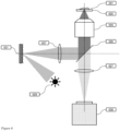
- Figure 6 illustrates an example of this embodiment using a Digital Micromirror Device (DMD) as the SLM in the excitation path of the microscope, where one orientation of the micromirrors reflects excitation light onto the sample, and the other orientation discards excitation light into a beam dump.
- DMD Digital Micromirror Device
- a different SLM such as an LCoS could also be used instead of a DMD, in which case the functionality stays the same but the overall layout of the optical paths is different. For simplicity, we will show examples using a DMD in the figures.
- the excitation light source (029) illuminates the DMD (031), which is positioned in the conjugate image plane defined by the microscope objective (005) and tube lens (027).
- the patterned excitation light from the DMD is coupled into the objective using the main dichroic (026) in a standard epifluorescence layout and projected through the microscope objective (005) onto the biological sample (001) mounted on the coverslip glass (025).
- the fluorescence light is imaged in the standard widefield emission pathway with a camera (030).
- the DMD is used to establish both the monitoring illumination and the regions of enhanced illumination.
- the percentage of time that a given DMD pixel is reflecting light to the sample is referred to as its duty cycle.
- the monitoring of the sample is achieved by running a low duty cycle pattern and the enhanced illumination is achieved by running a high duty cycle pattern over the corresponding pixels of the DMD.
- the average area of enhanced illumination is expected to be on the order of 1% of the field of view.
- B W the excitation that is required for monitoring the field of view for the appearance of new molecules.
- B DM the following relationship for the amount of background light expected from widefield excitation, B W , vs. dynamic masking, B DM , is obtained:
- B W B DM 1 f + m ⁇ 1 ⁇ f ⁇ 1 f + m
- f is the fraction of the area of the field of view over which the enhanced illumination is applied
- m is the relative excitation dose of the monitoring illumination intensity compared to the intensity in enhanced regions.
- the patterned illumination is created directly by a light source consisting of an array of individual light sources, which can be independently modulated in intensity.
- a light source would obviate the need for an SLM.
- such an array of light sources would be placed at the position of the DMD (031) in the image plane of the microscope.
- the SLM is not only located at the conjugate image plane in the excitation pathway, but also in the conjugate image plane in the emission pathway.
- Such an optical layout creates a confocal imaging device for which the pixels of the SLM function as confocal pinholes, akin to a spinning disk confocal microscope, allowing for rejection of a significant portion of the out-of-focus background fluorescence light from the sample.
- the SLM positioned at the conjugate image plane and employing dynamic masking, the signal-to-background ratio of detection is increased over that obtained by a spinning disk by ⁇ 1 f + m .
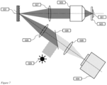
- Figure 7 illustrates an example of this embodiment using a DMD as the SLM.
- the DMD (031) is located in both the excitation and emission paths, with the dichroic mirror (026) that separates the excitation and emission light, placed in between the DMD and the camera (030).
- the emission light coming from the microscope objective (005) is first imaged onto the DMD using a tube lens (027), and subsequently imaged on the camera using a set of relay lenses (028).
- the non-conjugate out-of-focus light is captured by a detector instead of being simply discarded.
- Figure 8 illustrates an example of this embodiment using a DMD as the SLM.
- the non-conjugate out-of-focus light reflected by the DMD (031) is imaged by a second camera in an additional non-conjugate pathway (035) with respect to the existing conjugate pathway (034), akin to the optical layout of a PAM.
- Parallelized confocal detection across the field of view can lead to considerable crosstalk between the confocal pixels, amounting to an increase of out-of-focus background. This is a limitation common to spinning disk confocal microscopes, especially apparent when imaging thick or densely labeled samples. Detection of the rejected non-conjugate light by a camera yields a spatial image of the out-of-focus background fluorescence, and can function as a measure of the residual background in the conjugate image. A weighted subtraction of the non-conjugate image from the conjugate image allows elimination of the residual background in the optically sectioned image to the noise limit.
- the pixels of the DMD forming the regions of enhanced illumination should preferably use a 50% duty cycle, to allow for proper subtraction of the out-of-focus background.
- a 50% duty cycle for the regions of enhanced illumination.
- correct optical sectioning is still assured in the surrounding areas.
- a direct local measurement of the out-of-focus background is not available from the non-conjugate image, as no light is projected to the non-conjugate detector for these regions.
- a local non-conjugate estimate can still be derived based on the neighboring pixels in the non-conjugate image, allowing subtraction of the approximated contribution of out-of-focus background from the regions of enhanced illumination.
- the monitoring illumination is generated at a location different from the SLM, and the SLM is used solely for generating the regions of enhanced illumination.
- Figure 9 illustrates an example of this embodiment using a DMD as the SLM.
- This example is similar to the widefield microscope configuration show in Figure 6 , but with the addition of two further elements (032) and (033).
- the monitoring illumination (032) is generated at a different location from the DMD (031) and its corresponding light source (029). Both illuminations are then combined in the excitation path of the microscope using a beam combiner (033).
- This beam combiner can be selected to provide a specific ratio of the monitoring illumination and enhanced illumination from the DMD.
- the coupled beams could have different polarization, or be spectrally shifted, so as to use polarizing or dichroic beam combiners.
- the monitoring (032) is performed using an optical sectioning method, such as spinning disk confocal, slit scanning confocal or structured illumination, whereas the enhanced illumination is generated separately using an SLM and coupled into the excitation path using an appropriate beam combiner.
- an optical sectioning method such as spinning disk confocal, slit scanning confocal or structured illumination
- optical elements are added to the emission light path between the SLM and detector(s) to gain additional axial information for the individual fluorescent molecule emitters.
- Such axial information can be generated for example by the addition of a cylindrical lens or a diffractive element to distort the PSF of the particle in a predictable way, yielding information on its location above or below the focal plane.
- Dynamic masking using enhanced illumination is in principle compatible with the distortions introduced by these methods, as the regions surrounding the particles are large enough that they only increase signal from the individual emitters but should not otherwise significantly alter the distortion itself on which the axial determination is based.
- Another option would be to use an image splitter element to form multiple images at different focal planes on the detector.
- the axial information optical elements are included in both the conjugate and non-conjugate light paths to generate an equivalent distortion in the out-of-focus light in the non-conjugate image as in the conjugate image.
- the positioning of the axial information optical element in front of the non-conjugate detector need not be highly precise, as the non-conjugate image records only the out-of-focus light, and the exact distortion of the out-of-focus light by a slightly misaligned axial information optical element should not be critical.
- the regions of enhanced illumination within the patterned illumination are optimized for other SMLM localization modalities beyond centroid estimation by dynamic sub-sampling of the individual PSFs of the fluorescent molecule emitters by adjusting the size, shape, and position of each corresponding region of enhanced illumination.
- a triangulation in three dimensions can be performed, by adding a small displacement in depth, either by a displacement of the focus in the sample, or by using an SLM forming a digital hologram, where the individual focus spot can be varied in depth.
- 3D triangulation would furthermore allow extraction of the axial position of the emitter.
- the SLM could also be a holographic phase-based SLM. This approach has the potential to more efficiently use the excitation light and to thereby deliver higher intensity to the regions of enhanced illumination.
- Figure 10 illustrates an example for this embodiment where the excitation light (029) is modulated by a holographic SLM (038) located approximately in a plane conjugate to the back focal plane of the objective.
- a holographic SLM (038) located approximately in a plane conjugate to the back focal plane of the objective.
- a phase mask introduced by the SLM generates an illumination pattern in the image plane or a plane conjugated to the image plane (036), which can be calculated using a Fourier transformation or other algorithm. It could also make sense to remove the SLM from the conjugate plane to make sure that the zero-order light is not focused in the focal plane. Alternatively, the SLM could be illuminated with divergent light to remove the zero order light from the focal plane. One could also imagine that the zero-order light is used as the monitoring light to illuminate the full field, whereas the first order light is used as the patterned illumination for the molecules to be localized.
- the advantage of an SLM at the conjugate of the back focal plane of the objective is that the power of the light can be concentrated down to the positions of the molecules to be analyzed. Thus, the total intensity needed to illuminate the SLM could be orders of magnitude lower with respect to the case where the full field of interest is illuminated and only individual positions are switched on.
- the molecules are illuminated with tilted cones of light.
- Figure 11 illustrates the tilted cones of light onto the sample (panel A), as well as the required illumination areas at the back focal plane of the objective (panel B).
- the area illuminated on the SLM is imaged not to the center of the back focal plane (040) but acentric (041).
- the resulting patterned illumination is then comprised of light beams that are tilted with respect to the object plane.
- the tilt angle can be between 30 and almost 90 degrees to the object plane normal.
- the targeted fluorescent molecule emitter is thus illuminated by a tilted cone of light (039) in the focal plane. This already gives a local sectioning and reduction of background intensity. Fluorescent molecule emitters which are not in the object plane are only excited if they are laterally displaced from the focus along the tilt direction and thus can be recognized.
- This method may include exciting emitters (002) in parallel in a field of view of the objective lens with excitation light from an at least one first light source (029), and subsequent detection of the light emitted from the emitters in parallel as a result of the excitation light with an at least one first detector (030) to acquire an image. Approximate positions (022) of the emitters may then be determined based on the acquired images.
- Regions corresponding to the approximate positions of the emitters may be generated, wherein each region (023) is localized at each emitter in the subset and has characteristic dimensions comparable to the resolution limit of the microscope.
- a first patterned illumination (024) from at least one light source based on the regions may be adapted that illuminates a plurality of emitters in parallel in subsequent images. Repetition of the aforementioned steps in a continuous fashion constitutes a ⁇ dynamic masking' process (013), where the patterned illumination may be updated to account for the appearance and disappearance of the individual emitters in the field of view in the acquired images.
- This method may further include creating patterned illumination consisting of enhanced illumination within the regions corresponding to the approximate positions of the emitters, where the regions of enhanced illumination may receive more excitation light than the remaining portions of the field of view, and wherein the regions may be disposed so as to illuminate a plurality of emitters in parallel.
- an array of individual light sources may be used for the first light source, for which the patterned illumination could be created by altering the intensity of the individual light sources.
- This method may also include modulation of the light from the first light source through use of a spatial light modulator (SLM, 031) to establish the patterned illumination.
- SLM spatial light modulator
- This method may also include imaging the emitted light from the emitters onto the SLM, and then detecting the subsequent modulated emitted light using the first detector. In this way, modulation of the detected light from the emitters by the same subset of pixels of the SLM that modulate the light from the first light source onto the sample would allow for a confocal detection of the emitters through rejection of out-of-focus light by the remaining pixels of the SLM from the detected image.
- the methods above employing confocal detection may further include detection of the rejected out-of-focus light by the SLM by imaging that light onto at least one of an unused area of a surface of the first detector and a second detector.
- This method may further include removal of the residual out-of-focus light from a confocal image by scaled subtraction of the detected out-of-focus light.
- the above methods may also include sampling of the point-spread function (PSF) of each emitter in parallel by at least one of temporal and spatial modulation of the patterned illumination over the emitter.
- PSF point-spread function
- the method may also include the creation of tilted cones of light (039) onto each of the emitters with respect to the optical axis by illuminating the back focal plane (040) of the objective lens of the microscope acentric (041).
Landscapes
- Physics & Mathematics (AREA)
- Chemical & Material Sciences (AREA)
- Health & Medical Sciences (AREA)
- General Physics & Mathematics (AREA)
- Optics & Photonics (AREA)
- Analytical Chemistry (AREA)
- Immunology (AREA)
- Life Sciences & Earth Sciences (AREA)
- Biochemistry (AREA)
- General Health & Medical Sciences (AREA)
- Nuclear Medicine, Radiotherapy & Molecular Imaging (AREA)
- Pathology (AREA)
- Multimedia (AREA)
- Engineering & Computer Science (AREA)
- Chemical Kinetics & Catalysis (AREA)
- Molecular Biology (AREA)
- Computer Vision & Pattern Recognition (AREA)
- Microscoopes, Condenser (AREA)
- Investigating, Analyzing Materials By Fluorescence Or Luminescence (AREA)
- Image Analysis (AREA)
Applications Claiming Priority (1)
| Application Number | Priority Date | Filing Date | Title |
|---|---|---|---|
| US202263321152P | 2022-03-18 | 2022-03-18 |
Publications (1)
| Publication Number | Publication Date |
|---|---|
| EP4246205A1 true EP4246205A1 (en) | 2023-09-20 |
Family
ID=85601717
Family Applications (1)
| Application Number | Title | Priority Date | Filing Date |
|---|---|---|---|
| EP23161518.8A Withdrawn EP4246205A1 (en) | 2022-03-18 | 2023-03-13 | Method for single molecule localization microscopy |
Country Status (3)
| Country | Link |
|---|---|
| US (1) | US12560540B2 (https=) |
| EP (1) | EP4246205A1 (https=) |
| JP (1) | JP2023138481A (https=) |
Cited By (1)
| Publication number | Priority date | Publication date | Assignee | Title |
|---|---|---|---|---|
| EP4550021A1 (en) * | 2023-11-06 | 2025-05-07 | Valstybinis Moksliniu Tyrimu Institutas Fiziniu Ir Technologijos Mokslu Centras | Fast and programmable reflectance confocal microscopy with digital micromirror device |
Families Citing this family (2)
| Publication number | Priority date | Publication date | Assignee | Title |
|---|---|---|---|---|
| WO2025104049A1 (en) | 2023-11-14 | 2025-05-22 | Miltenyi Biotec B.V. & Co. KG | Background-free immunofluorescence using transient molecule binders |
| WO2025125533A1 (en) * | 2023-12-15 | 2025-06-19 | Miltenyi Biotec B.V. & Co. KG | A method for single molecule localization microscopy at ångstrom resolution based on conventional fluorophore-labeled antibody probes |
Family Cites Families (5)
| Publication number | Priority date | Publication date | Assignee | Title |
|---|---|---|---|---|
| US6663560B2 (en) * | 1999-12-17 | 2003-12-16 | Digital Optical Imaging Corporation | Methods and apparatus for imaging using a light guide bundle and a spatial light modulator |
| DE102008059328A1 (de) | 2008-11-27 | 2010-06-02 | Carl Zeiss Microimaging Gmbh | Auflösungsgesteigerte Mikroskopie |
| WO2015017730A1 (en) * | 2013-07-31 | 2015-02-05 | California Institute Of Technoloby | Aperture scanning fourier ptychographic imaging |
| US10264190B2 (en) * | 2015-04-24 | 2019-04-16 | Omnitek Partners Llc | Adaptive optical methods and devices for enhancing image contrast in the presence of bright background |
| KR102451422B1 (ko) * | 2020-11-24 | 2022-10-07 | 울산과학기술원 | 초고해상도 이미지와 고속 광시야 이미지를 동시에 획득하는 방법 및 장치 |
-
2023
- 2023-02-21 US US18/111,991 patent/US12560540B2/en active Active
- 2023-03-13 EP EP23161518.8A patent/EP4246205A1/en not_active Withdrawn
- 2023-03-17 JP JP2023042713A patent/JP2023138481A/ja active Pending
Non-Patent Citations (5)
| Title |
|---|
| LIU SHENG ET AL: "Three-Dimensional Single-Molecule Localization Microscopy in Whole-Cell and Tissue Specimens", 3 April 2020 (2020-04-03), XP093071768, Retrieved from the Internet <URL:https://www.annualreviews.org/doi/abs/10.1146/annurev-bioeng-060418-052203> [retrieved on 20230808], DOI: 10.1146/annurev-bioeng-060418- * |
| LIYANA VALIYA PEEDIKAKKAL ET AL: "Development of targeted STORM for super resolution imaging of biological samples using digital micro-mirror device", OPTICS COMMUNICATIONS, vol. 404, 1 December 2017 (2017-12-01), AMSTERDAM, NL, pages 18 - 22, XP055521466, ISSN: 0030-4018, DOI: 10.1016/j.optcom.2017.06.055 * |
| PEEDIKAKKAL LIYANA VALIYA ET AL: "A Multimodal Adaptive Super-Resolution and Confocal Microscope", BIORXIV, 24 August 2018 (2018-08-24), XP093071741, Retrieved from the Internet <URL:https://www.biorxiv.org/content/10.1101/397273v2.full> [retrieved on 20230808], DOI: 10.1101/397273 * |
| RICARDO HENRIQUES ET AL: "PALM and STORM: Unlocking live-cell super-resolution", BIOPOLYMERS, JOHN WILEY, HOBOKEN, USA, vol. 95, no. 5, 19 January 2011 (2011-01-19), pages 322 - 331, XP071150836, ISSN: 0006-3525, DOI: 10.1002/BIP.21586 * |
| WASISTO HUTOMO SURYO ET AL: "Beyond solid-state lighting: Miniaturization, hybrid integration, and applications of GaN nano- and micro-LEDs", APPLIED PHYSICS REVIEWS, AMERICAN INSTITUTE OF PHYSICS, 2 HUNTINGTON QUADRANGLE, MELVILLE, NY 11747, vol. 6, no. 4, 19 December 2019 (2019-12-19), XP012243352, DOI: 10.1063/1.5096322 * |
Cited By (1)
| Publication number | Priority date | Publication date | Assignee | Title |
|---|---|---|---|---|
| EP4550021A1 (en) * | 2023-11-06 | 2025-05-07 | Valstybinis Moksliniu Tyrimu Institutas Fiziniu Ir Technologijos Mokslu Centras | Fast and programmable reflectance confocal microscopy with digital micromirror device |
Also Published As
| Publication number | Publication date |
|---|---|
| US20230296515A1 (en) | 2023-09-21 |
| JP2023138481A (ja) | 2023-10-02 |
| US12560540B2 (en) | 2026-02-24 |
Similar Documents
| Publication | Publication Date | Title |
|---|---|---|
| EP4246205A1 (en) | Method for single molecule localization microscopy | |
| US8704196B2 (en) | Combination microscopy | |
| JP5738765B2 (ja) | 構造化照明を備えた顕微鏡法のための改良された方法および装置 | |
| Bayguinov et al. | Modern laser scanning confocal microscopy | |
| JP3731073B2 (ja) | 顕微鏡装置 | |
| US6088097A (en) | Point-scanning luminescent microscope | |
| JP5485352B2 (ja) | 解像度を高めたルミネセンス顕微鏡検査 | |
| US7679741B2 (en) | Method and microscope for high spatial resolution examination of samples | |
| US7706584B2 (en) | Random access high-speed confocal microscope | |
| JP6329896B2 (ja) | 高分解能ルミネッセンス顕微鏡法 | |
| US20110267688A1 (en) | Microscopy Method and Microscope With Enhanced Resolution | |
| US11237370B2 (en) | Multiple inclined beam line-scanning imaging apparatus, methods, and applications | |
| US20130068967A1 (en) | Method for Generating a Microscope Image and Microscope | |
| US20130087718A1 (en) | Confocal fluorescence lifetime imaging system | |
| CN107850765A (zh) | 光束成形和光层显微技术的方法和组合件 | |
| US11885947B2 (en) | Lattice light sheet microscope and method for tiling lattice light sheet in lattice light sheet microscope | |
| JP7701357B2 (ja) | ダークトラッキング、ハイブリッド方法、円錐回折顕微鏡法、及びダークアドレッシング | |
| CN116670492A (zh) | 用于记录样本中单个粒子的轨迹的方法和显微镜 | |
| Naredi‐Rainer et al. | Confocal microscopy | |
| NL2008873C2 (en) | Method and apparatus for multiple points of view three-dimensional microscopy. | |
| Zhang et al. | A new multichannel spectral imaging laser scanning confocal microscope | |
| CN119414583A (zh) | 一种单分子显微成像工业相机成像系统及成像方法 | |
| Fuseler et al. | Types of confocal instruments: Basic principles and advantages and disadvantages | |
| US12124019B2 (en) | Microscope with a wide-field illuminator and a common detection objective for a camera detector and a point detector | |
| CN120195857B (zh) | 一种基于转盘的双重共聚焦图像扫描显微镜及成像方法 |
Legal Events
| Date | Code | Title | Description |
|---|---|---|---|
| PUAI | Public reference made under article 153(3) epc to a published international application that has entered the european phase |
Free format text: ORIGINAL CODE: 0009012 |
|
| STAA | Information on the status of an ep patent application or granted ep patent |
Free format text: STATUS: THE APPLICATION HAS BEEN PUBLISHED |
|
| AK | Designated contracting states |
Kind code of ref document: A1 Designated state(s): AL AT BE BG CH CY CZ DE DK EE ES FI FR GB GR HR HU IE IS IT LI LT LU LV MC ME MK MT NL NO PL PT RO RS SE SI SK SM TR |
|
| STAA | Information on the status of an ep patent application or granted ep patent |
Free format text: STATUS: THE APPLICATION IS DEEMED TO BE WITHDRAWN |
|
| 18D | Application deemed to be withdrawn |
Effective date: 20240321 |