EP4246055A1 - Control device, exhaust heat recovery freezer system, control method, and program - Google Patents
Control device, exhaust heat recovery freezer system, control method, and program Download PDFInfo
- Publication number
- EP4246055A1 EP4246055A1 EP23153347.2A EP23153347A EP4246055A1 EP 4246055 A1 EP4246055 A1 EP 4246055A1 EP 23153347 A EP23153347 A EP 23153347A EP 4246055 A1 EP4246055 A1 EP 4246055A1
- Authority
- EP
- European Patent Office
- Prior art keywords
- heat recovery
- supercritical
- exhaust heat
- freezer
- refrigerant circuit
- Prior art date
- Legal status (The legal status is an assumption and is not a legal conclusion. Google has not performed a legal analysis and makes no representation as to the accuracy of the status listed.)
- Granted
Links
Images


Classifications
-
- F—MECHANICAL ENGINEERING; LIGHTING; HEATING; WEAPONS; BLASTING
- F25—REFRIGERATION OR COOLING; COMBINED HEATING AND REFRIGERATION SYSTEMS; HEAT PUMP SYSTEMS; MANUFACTURE OR STORAGE OF ICE; LIQUEFACTION SOLIDIFICATION OF GASES
- F25B—REFRIGERATION MACHINES, PLANTS OR SYSTEMS; COMBINED HEATING AND REFRIGERATION SYSTEMS; HEAT PUMP SYSTEMS
- F25B6/00—Compression machines, plants or systems, with several condenser circuits
- F25B6/04—Compression machines, plants or systems, with several condenser circuits arranged in series
-
- F—MECHANICAL ENGINEERING; LIGHTING; HEATING; WEAPONS; BLASTING
- F24—HEATING; RANGES; VENTILATING
- F24H—FLUID HEATERS, e.g. WATER OR AIR HEATERS, HAVING HEAT-GENERATING MEANS, e.g. HEAT PUMPS, IN GENERAL
- F24H15/00—Control of fluid heaters
- F24H15/20—Control of fluid heaters characterised by control inputs
- F24H15/227—Temperature of the refrigerant in heat pump cycles
-
- F—MECHANICAL ENGINEERING; LIGHTING; HEATING; WEAPONS; BLASTING
- F24—HEATING; RANGES; VENTILATING
- F24H—FLUID HEATERS, e.g. WATER OR AIR HEATERS, HAVING HEAT-GENERATING MEANS, e.g. HEAT PUMPS, IN GENERAL
- F24H15/00—Control of fluid heaters
- F24H15/20—Control of fluid heaters characterised by control inputs
- F24H15/254—Room temperature
-
- F—MECHANICAL ENGINEERING; LIGHTING; HEATING; WEAPONS; BLASTING
- F24—HEATING; RANGES; VENTILATING
- F24H—FLUID HEATERS, e.g. WATER OR AIR HEATERS, HAVING HEAT-GENERATING MEANS, e.g. HEAT PUMPS, IN GENERAL
- F24H15/00—Control of fluid heaters
- F24H15/30—Control of fluid heaters characterised by control outputs; characterised by the components to be controlled
- F24H15/375—Control of heat pumps
-
- F—MECHANICAL ENGINEERING; LIGHTING; HEATING; WEAPONS; BLASTING
- F24—HEATING; RANGES; VENTILATING
- F24H—FLUID HEATERS, e.g. WATER OR AIR HEATERS, HAVING HEAT-GENERATING MEANS, e.g. HEAT PUMPS, IN GENERAL
- F24H15/00—Control of fluid heaters
- F24H15/40—Control of fluid heaters characterised by the type of controllers
- F24H15/414—Control of fluid heaters characterised by the type of controllers using electronic processing, e.g. computer-based
- F24H15/421—Control of fluid heaters characterised by the type of controllers using electronic processing, e.g. computer-based using pre-stored data
- F24H15/429—Control of fluid heaters characterised by the type of controllers using electronic processing, e.g. computer-based using pre-stored data for selecting operation modes
-
- F—MECHANICAL ENGINEERING; LIGHTING; HEATING; WEAPONS; BLASTING
- F25—REFRIGERATION OR COOLING; COMBINED HEATING AND REFRIGERATION SYSTEMS; HEAT PUMP SYSTEMS; MANUFACTURE OR STORAGE OF ICE; LIQUEFACTION SOLIDIFICATION OF GASES
- F25B—REFRIGERATION MACHINES, PLANTS OR SYSTEMS; COMBINED HEATING AND REFRIGERATION SYSTEMS; HEAT PUMP SYSTEMS
- F25B29/00—Combined heating and refrigeration systems, e.g. operating alternately or simultaneously
- F25B29/003—Combined heating and refrigeration systems, e.g. operating alternately or simultaneously of the compression type system
-
- F—MECHANICAL ENGINEERING; LIGHTING; HEATING; WEAPONS; BLASTING
- F25—REFRIGERATION OR COOLING; COMBINED HEATING AND REFRIGERATION SYSTEMS; HEAT PUMP SYSTEMS; MANUFACTURE OR STORAGE OF ICE; LIQUEFACTION SOLIDIFICATION OF GASES
- F25B—REFRIGERATION MACHINES, PLANTS OR SYSTEMS; COMBINED HEATING AND REFRIGERATION SYSTEMS; HEAT PUMP SYSTEMS
- F25B30/00—Heat pumps
- F25B30/02—Heat pumps of the compression type
-
- F—MECHANICAL ENGINEERING; LIGHTING; HEATING; WEAPONS; BLASTING
- F25—REFRIGERATION OR COOLING; COMBINED HEATING AND REFRIGERATION SYSTEMS; HEAT PUMP SYSTEMS; MANUFACTURE OR STORAGE OF ICE; LIQUEFACTION SOLIDIFICATION OF GASES
- F25B—REFRIGERATION MACHINES, PLANTS OR SYSTEMS; COMBINED HEATING AND REFRIGERATION SYSTEMS; HEAT PUMP SYSTEMS
- F25B49/00—Arrangement or mounting of control or safety devices
- F25B49/02—Arrangement or mounting of control or safety devices for compression type machines, plants or systems
-
- F—MECHANICAL ENGINEERING; LIGHTING; HEATING; WEAPONS; BLASTING
- F25—REFRIGERATION OR COOLING; COMBINED HEATING AND REFRIGERATION SYSTEMS; HEAT PUMP SYSTEMS; MANUFACTURE OR STORAGE OF ICE; LIQUEFACTION SOLIDIFICATION OF GASES
- F25B—REFRIGERATION MACHINES, PLANTS OR SYSTEMS; COMBINED HEATING AND REFRIGERATION SYSTEMS; HEAT PUMP SYSTEMS
- F25B49/00—Arrangement or mounting of control or safety devices
- F25B49/02—Arrangement or mounting of control or safety devices for compression type machines, plants or systems
- F25B49/022—Compressor control arrangements
-
- F—MECHANICAL ENGINEERING; LIGHTING; HEATING; WEAPONS; BLASTING
- F25—REFRIGERATION OR COOLING; COMBINED HEATING AND REFRIGERATION SYSTEMS; HEAT PUMP SYSTEMS; MANUFACTURE OR STORAGE OF ICE; LIQUEFACTION SOLIDIFICATION OF GASES
- F25B—REFRIGERATION MACHINES, PLANTS OR SYSTEMS; COMBINED HEATING AND REFRIGERATION SYSTEMS; HEAT PUMP SYSTEMS
- F25B49/00—Arrangement or mounting of control or safety devices
- F25B49/02—Arrangement or mounting of control or safety devices for compression type machines, plants or systems
- F25B49/027—Condenser control arrangements
-
- F—MECHANICAL ENGINEERING; LIGHTING; HEATING; WEAPONS; BLASTING
- F25—REFRIGERATION OR COOLING; COMBINED HEATING AND REFRIGERATION SYSTEMS; HEAT PUMP SYSTEMS; MANUFACTURE OR STORAGE OF ICE; LIQUEFACTION SOLIDIFICATION OF GASES
- F25B—REFRIGERATION MACHINES, PLANTS OR SYSTEMS; COMBINED HEATING AND REFRIGERATION SYSTEMS; HEAT PUMP SYSTEMS
- F25B9/00—Compression machines, plants or systems, in which the refrigerant is air or other gas of low boiling point
- F25B9/002—Compression machines, plants or systems, in which the refrigerant is air or other gas of low boiling point characterised by the refrigerant
- F25B9/008—Compression machines, plants or systems, in which the refrigerant is air or other gas of low boiling point characterised by the refrigerant the refrigerant being carbon dioxide
-
- F—MECHANICAL ENGINEERING; LIGHTING; HEATING; WEAPONS; BLASTING
- F24—HEATING; RANGES; VENTILATING
- F24D—DOMESTIC- OR SPACE-HEATING SYSTEMS, e.g. CENTRAL HEATING SYSTEMS; DOMESTIC HOT-WATER SUPPLY SYSTEMS; ELEMENTS OR COMPONENTS THEREFOR
- F24D19/00—Details
- F24D19/10—Arrangement or mounting of control or safety devices
- F24D19/1006—Arrangement or mounting of control or safety devices for water heating systems
- F24D19/1009—Arrangement or mounting of control or safety devices for water heating systems for central heating
- F24D19/1039—Arrangement or mounting of control or safety devices for water heating systems for central heating the system uses a heat pump
-
- F—MECHANICAL ENGINEERING; LIGHTING; HEATING; WEAPONS; BLASTING
- F24—HEATING; RANGES; VENTILATING
- F24D—DOMESTIC- OR SPACE-HEATING SYSTEMS, e.g. CENTRAL HEATING SYSTEMS; DOMESTIC HOT-WATER SUPPLY SYSTEMS; ELEMENTS OR COMPONENTS THEREFOR
- F24D2200/00—Heat sources or energy sources
- F24D2200/12—Heat pump
- F24D2200/123—Compression type heat pumps
-
- F—MECHANICAL ENGINEERING; LIGHTING; HEATING; WEAPONS; BLASTING
- F24—HEATING; RANGES; VENTILATING
- F24D—DOMESTIC- OR SPACE-HEATING SYSTEMS, e.g. CENTRAL HEATING SYSTEMS; DOMESTIC HOT-WATER SUPPLY SYSTEMS; ELEMENTS OR COMPONENTS THEREFOR
- F24D2200/00—Heat sources or energy sources
- F24D2200/16—Waste heat
- F24D2200/24—Refrigeration
-
- F—MECHANICAL ENGINEERING; LIGHTING; HEATING; WEAPONS; BLASTING
- F25—REFRIGERATION OR COOLING; COMBINED HEATING AND REFRIGERATION SYSTEMS; HEAT PUMP SYSTEMS; MANUFACTURE OR STORAGE OF ICE; LIQUEFACTION SOLIDIFICATION OF GASES
- F25B—REFRIGERATION MACHINES, PLANTS OR SYSTEMS; COMBINED HEATING AND REFRIGERATION SYSTEMS; HEAT PUMP SYSTEMS
- F25B1/00—Compression machines, plants or systems with non-reversible cycle
- F25B1/10—Compression machines, plants or systems with non-reversible cycle with multi-stage compression
-
- F—MECHANICAL ENGINEERING; LIGHTING; HEATING; WEAPONS; BLASTING
- F25—REFRIGERATION OR COOLING; COMBINED HEATING AND REFRIGERATION SYSTEMS; HEAT PUMP SYSTEMS; MANUFACTURE OR STORAGE OF ICE; LIQUEFACTION SOLIDIFICATION OF GASES
- F25B—REFRIGERATION MACHINES, PLANTS OR SYSTEMS; COMBINED HEATING AND REFRIGERATION SYSTEMS; HEAT PUMP SYSTEMS
- F25B2309/00—Gas cycle refrigeration machines
- F25B2309/06—Compression machines, plants or systems characterised by the refrigerant being carbon dioxide
- F25B2309/061—Compression machines, plants or systems characterised by the refrigerant being carbon dioxide with cycle highest pressure above the supercritical pressure
-
- F—MECHANICAL ENGINEERING; LIGHTING; HEATING; WEAPONS; BLASTING
- F25—REFRIGERATION OR COOLING; COMBINED HEATING AND REFRIGERATION SYSTEMS; HEAT PUMP SYSTEMS; MANUFACTURE OR STORAGE OF ICE; LIQUEFACTION SOLIDIFICATION OF GASES
- F25B—REFRIGERATION MACHINES, PLANTS OR SYSTEMS; COMBINED HEATING AND REFRIGERATION SYSTEMS; HEAT PUMP SYSTEMS
- F25B2339/00—Details of evaporators; Details of condensers
- F25B2339/04—Details of condensers
- F25B2339/047—Water-cooled condensers
-
- F—MECHANICAL ENGINEERING; LIGHTING; HEATING; WEAPONS; BLASTING
- F25—REFRIGERATION OR COOLING; COMBINED HEATING AND REFRIGERATION SYSTEMS; HEAT PUMP SYSTEMS; MANUFACTURE OR STORAGE OF ICE; LIQUEFACTION SOLIDIFICATION OF GASES
- F25B—REFRIGERATION MACHINES, PLANTS OR SYSTEMS; COMBINED HEATING AND REFRIGERATION SYSTEMS; HEAT PUMP SYSTEMS
- F25B2400/00—Component parts or details not otherwise provided for in this subclass
- F25B2400/22—Refrigeration systems for supermarkets
-
- F—MECHANICAL ENGINEERING; LIGHTING; HEATING; WEAPONS; BLASTING
- F25—REFRIGERATION OR COOLING; COMBINED HEATING AND REFRIGERATION SYSTEMS; HEAT PUMP SYSTEMS; MANUFACTURE OR STORAGE OF ICE; LIQUEFACTION SOLIDIFICATION OF GASES
- F25B—REFRIGERATION MACHINES, PLANTS OR SYSTEMS; COMBINED HEATING AND REFRIGERATION SYSTEMS; HEAT PUMP SYSTEMS
- F25B2400/00—Component parts or details not otherwise provided for in this subclass
- F25B2400/23—Separators
-
- F—MECHANICAL ENGINEERING; LIGHTING; HEATING; WEAPONS; BLASTING
- F25—REFRIGERATION OR COOLING; COMBINED HEATING AND REFRIGERATION SYSTEMS; HEAT PUMP SYSTEMS; MANUFACTURE OR STORAGE OF ICE; LIQUEFACTION SOLIDIFICATION OF GASES
- F25B—REFRIGERATION MACHINES, PLANTS OR SYSTEMS; COMBINED HEATING AND REFRIGERATION SYSTEMS; HEAT PUMP SYSTEMS
- F25B2600/00—Control issues
- F25B2600/02—Compressor control
- F25B2600/025—Compressor control by controlling speed
- F25B2600/0253—Compressor control by controlling speed with variable speed
-
- F—MECHANICAL ENGINEERING; LIGHTING; HEATING; WEAPONS; BLASTING
- F25—REFRIGERATION OR COOLING; COMBINED HEATING AND REFRIGERATION SYSTEMS; HEAT PUMP SYSTEMS; MANUFACTURE OR STORAGE OF ICE; LIQUEFACTION SOLIDIFICATION OF GASES
- F25B—REFRIGERATION MACHINES, PLANTS OR SYSTEMS; COMBINED HEATING AND REFRIGERATION SYSTEMS; HEAT PUMP SYSTEMS
- F25B2600/00—Control issues
- F25B2600/02—Compressor control
- F25B2600/027—Compressor control by controlling pressure
- F25B2600/0271—Compressor control by controlling pressure the discharge pressure
Definitions
- the present invention relates to a control device, an exhaust heat recovery freezer system, a control method, and a program.
- Priority is claimed on Japanese Patent Application No. 2022-040662, filed March 15, 2022 , the content of which is incorporated herein by reference and to which the person of the art can refer to when considering the present disclosure.
- Patent Document 1 discloses control in which heat discharged from a freezer using a CO 2 refrigerant when a show case in a store is cooled using the freezer is utilized for hot water or heating. Specifically, Patent Document 1 discloses control in which a part of a refrigerant emitted by a compressor is supplied to a radiator unit and utilized for heating and water which has been heat-exchanged in a condenser is utilized as hot water. In addition, Patent Document 2 discloses an air conditioner using a CO 2 refrigerant with a freezing cycle in which a high pressure is in a supercritical state when a cooling operation is performed in normal environmental conditions and the high pressure is in a subcritical state in a state in which the outside air temperature is low.
- an object of this invention is to provide a control device, an exhaust heat recovery freezer system, a control method, and a program capable of resolving the problems described above.
- a control device includes an operation mode decision unit that decides, in accordance with necessity of heat recovery from a refrigerant circulating in a refrigerant circuit, which operation of a supercritical operation in which a high pressure in the refrigerant circuit is in a supercritical state and a subcritical operation in which the high pressure is in a subcritical state is to be performed; and a freezer control unit that controls the refrigerant circuit to be operated in either the supercritical operation or the subcritical operation on the basis of decision of the operation mode decision unit.
- an exhaust heat recovery freezer system includes a freezer that has a refrigerant circuit including a compressor, a gas cooler, an expansion valve, and an evaporator; an exhaust heat recovery device that recovers heat through heat exchange with a refrigerant circulating in the refrigerant circuit between the compressor and the gas cooler in the refrigerant circuit and supplies the recovered heat to a load device; and the foregoing control device.
- a control method includes a step of deciding, in accordance with necessity of heat recovery from a refrigerant circulating in a refrigerant circuit, which operation of a supercritical operation in which a high pressure in the refrigerant circuit is in a supercritical state and a subcritical operation in which the high pressure is in a subcritical state is to be performed; and a step of controlling the refrigerant circuit to be operated in either the supercritical operation or the subcritical operation on the basis of decision in the step of deciding an operation.
- a program causes a computer to execute a step of deciding, in accordance with necessity of heat recovery from a refrigerant circulating in a refrigerant circuit, which operation of a supercritical operation in which a high pressure in the refrigerant circuit is in a supercritical state and a subcritical operation in which the high pressure is in a subcritical state is to be performed; and a step of controlling the refrigerant circuit to be operated in either the supercritical operation or the subcritical operation on the basis of decision in the step of deciding an operation.
- the control device the exhaust heat recovery freezer system, the control method, and the program of the present disclosure, it is possible to improve overall efficiency of both a load device, which utilizes exhaust heat of a freezer, and the freezer.
- FIG. 1 is a diagram illustrating an example of an exhaust heat recovery freezer system according to the embodiment.
- An exhaust heat recovery freezer system 1 is a system in which heat discharged by a freezer 10 performing a cooling operation is recovered by an exhaust heat recovery device 20 and the recovered heat is supplied to a warming cycle of a high-temperature load device 30.
- the exhaust heat recovery freezer system 1 is used in supermarkets or the like, in which the freezer 10 refrigerates or freezes food and exhaust heat therefrom is recovered by the exhaust heat recovery device 20 and utilized for heating of the store or in a water heater.
- CO 2 is used as a refrigerant.
- a CO 2 refrigerant is in a supercritical state within an ordinary temperature range at approximately 31°C.
- the exhaust heat recovery freezer system 1 determines necessity of heat recovery by the exhaust heat recovery device 20 and operates with a high pressure in the freezer 10 in a supercritical state or a subcritical state in accordance with the necessity thereof.
- the exhaust heat recovery freezer system 1 includes the freezer 10, the exhaust heat recovery device 20, the high-temperature load device 30, a low-temperature load device 31 (for example, a refrigerating show case or a freezing show case in a supermarket), and a system controller 40.
- the freezer 10 includes a two-stage compressor 11, a gas cooler 12, a first expansion valve 13a, a receiver 14, an accumulator 16, a main piping 17 connecting these to the low-temperature load device 31, a piping 18 connecting a gas-phase portion of the receiver 14 to an emission side of a low stage-side compressor 11b of a high stage-side compressor 11a and the low stage-side compressor 11b included in the two-stage compressor 11, a valve 18a controlling a flow rate of the refrigerant flowing in the piping 18, a fan 19 provided in the gas cooler 12, and temperature sensors tho 1 to tho3.
- the temperature sensor tho 1 is provided on the emission side of the two-stage compressor 11 and an entrance side of a heat exchanger 21, and the temperature sensor tho2 is provided on an exit side of the heat exchanger 21 and the entrance side of the gas cooler 12.
- the exit side and the entrance side are an exit side and an entrance side in a flowing direction of the refrigerant.
- the temperature sensor tho3 is provided at a position where an outside air temperature can be measured.
- the low-temperature load device 31 is constituted of a second expansion valve 13b and an evaporator 15 and is connected to a low pressure side of the freezer 10.
- the heat exchanger 21 of the exhaust heat recovery device 20 is connected (inserted) between the two-stage compressor 11 and the gas cooler 12, and the CO 2 refrigerant of the freezer 10 flows in the heat exchanger 21.
- the exhaust heat recovery device 20 includes the heat exchanger 21 for exhaust heat recovery, a pump 22, and a piping 23 connecting these to the high-temperature load device 30.
- the high-temperature load device 30 is an air conditioner, a water heater, or the like in a store.
- heat exchange heat exchange is performed between the CO 2 refrigerant of the freezer 10 and the refrigerant (for example, water) of the exhaust heat recovery device 20.
- warm water which has been warmed through heat exchange in the heat exchanger 21 circulates in the piping 23 by driving of the pump 22, and for example, exhaust heat from the freezer 10 is supplied to the high-temperature load device 30 via a heat exchanger (not shown) provided in the high-temperature load device 30. Since the refrigerant does not circulate in the piping 23 when the pump 22 is at a stop, exhaust heat is not recovered by the exhaust heat recovery device 20.
- the two-stage compressor 11 emits a high-pressure refrigerant compressed by the high stage-side compressor 11a and the low stage-side compressor 11b.
- a suction side of the low stage-side compressor 11b is connected to the accumulator 16, and the low stage-side compressor 11b suctions and compresses the refrigerant (gas) separated by the accumulator 16.
- the low stage-side compressor 11b emits the compressed refrigerant to the suction side of the high stage-side compressor 11a.
- the refrigerant is supplied from the gas-phase portion of the receiver 14 to the suction side of the high stage-side compressor 11a through the piping 18 (injection circuit).
- the high stage-side compressor 11a suctions and compresses these refrigerants.
- the compressed refrigerant is supplied to the heat exchanger 21 for exhaust heat recovery.
- heat of the high-temperature/high-pressure CO 2 refrigerant is recovered by the refrigerant (water) of the exhaust heat recovery device 20 and is supplied to the high-temperature load device 30.
- the CO 2 refrigerant which has passed through the heat exchanger 21 is subjected to heat dissipation through heat exchange in the gas cooler 12 with air sent by the fan 19 and is condensed and liquefied.
- the condensed refrigerant is subjected to pressure reduction and expansion by the first expansion valve 13a and is supplied to the receiver 14.
- a two-phase refrigerant of gas and liquid is present in a mixed manner.
- a part (gas-phase portion) of the refrigerant present in the receiver 14 branches to the piping 18 as described above and is supplied to the two-stage compressor 11.
- the CO 2 refrigerant supplied to the evaporator 15 absorbs heat of the low-temperature load device 31 (for example, a show case for refrigeration or a show case for freezing in a store), is gasified, and cools the low-temperature load device 31.
- the CO 2 refrigerant gasified by the evaporator 15 is supplied to the accumulator 16.
- the CO 2 refrigerant is separated into gas and liquid by the accumulator 16, and the gas refrigerant is suctioned into the low stage-side compressor 11b.
- the refrigerant is compressed by the low stage-side compressor 11b and the high stage-side compressor 11a and circulates through the foregoing path again.
- the exhaust heat recovery freezer system 1 shown in FIG. 1 is a schematic basic constitution and may further include other constituent elements.
- the exhaust heat recovery device 20 has only one heat exchanger 21, but the exhaust heat recovery device 20 may include two or more heat exchangers 21. In this case, all or some of the plurality of heat exchangers 21 may be connected to (inserted into) a refrigerant circuit of the freezer 10.
- a plurality of exhaust heat recovery devices 20 may be present, and the heat exchanger 21 provided in each exhaust heat recovery device 20 may be connected to the refrigerant circuit of the freezer 10.
- the system controller 40 controls the freezer 10 and the exhaust heat recovery device 20.
- the system controller 40 includes a signal acquisition unit 41, a setting reception unit 42, an exhaust heat recovery device control unit 43, an operation mode decision unit 44, a freezer control unit 45, and a storage unit 46.
- the system controller 40 has a timer, which can recognize the current date and time.
- the signal acquisition unit 41 acquires the temperature detected by the temperature sensors tho1 to tho3, a signal indicating a working state of the exhaust heat recovery device 20, and a signal indicating an operation state (a working state or a load state) of the high-temperature load device 30.
- the signal acquisition unit 41 records various kinds of acquired signals in the storage unit 46.
- the setting reception unit 42 receives an input of various kinds of settings made by a user. For example, the setting reception unit 42 receives a setting for working (ON) or stopping (OFF) of the exhaust heat recovery device 20 and outputs the setting to the exhaust heat recovery device control unit 43. In addition, regarding the operation of the freezer 10, the setting reception unit 42 receives a setting of conditions for switching between an operation in which the high pressure is in the supercritical state (which may hereinafter be referred to as a supercritical operation) and an operation in which the high pressure is in the subcritical state (which may hereinafter be referred to as a subcritical operation) and records the received setting of the conditions for switching in the storage unit 46.
- a supercritical operation which may hereinafter be referred to as a supercritical operation
- a subcritical operation which the high pressure is in the subcritical state
- the exhaust heat recovery device control unit 43 controls working (ON) and stopping (OFF) of the exhaust heat recovery device 20. For example, when a user performs setting for causing the exhaust heat recovery device 20 to work, the exhaust heat recovery device control unit 43 acquires the setting through the setting reception unit 42 and causes the exhaust heat recovery device 20 to work by starting the pump 22, or the like. When a user performs setting for causing the exhaust heat recovery device 20 to stop, the exhaust heat recovery device control unit 43 acquires the setting through the setting reception unit 42 and causes the exhaust heat recovery device 20 to stop by stopping the pump 22, or the like. When the exhaust heat recovery device 20 is caused to work or stop, the exhaust heat recovery device control unit 43 records the time at which the control is performed and the executed operation of either working or stopping in the storage unit 46 as a working log.
- the operation mode decision unit 44 determines necessity of exhaust heat recovery and decides the operation mode of the freezer 10 on the basis of the outside air temperature acquired by the signal acquisition unit 41, the working state of the exhaust heat recovery device 20, the load state of the high-temperature load device 30, and the setting of the conditions for switching recorded in the storage unit 46 by the setting reception unit 42.
- the operation mode is either the supercritical operation or the subcritical operation. For example, when the efficiency of the exhaust heat recovery freezer system 1 in its entirety is improved by intensifying exhaust heat recovery, the operation mode decision unit 44 determines that necessity of exhaust heat recovery is high. If not, it is determined that necessity of exhaust heat recovery is low. When necessity of exhaust heat recovery is high, the operation mode decision unit 44 decides that the supercritical operation is performed, and when necessity of exhaust heat recovery is not high, it is decided that the subcritical operation is performed.
- the freezer control unit 45 causes the freezer 10 to operate in the operation mode decided by the operation mode decision unit 44.
- the two-stage compressor 11 is constituted to operate with a rotation frequency in which the pressure on the high-pressure side is in the supercritical state when instructed to perform the supercritical operation and to operate with a rotation frequency in which the pressure on the high-pressure side is in the subcritical state when instructed to perform the subcritical operation.
- the freezer control unit 45 instructs the two-stage compressor 11 to perform the supercritical operation.
- the freezer control unit 45 instructs the two-stage compressor 11 to perform the subcritical operation.
- the freezer control unit 45 performs various kinds of control related to the freezer 10, but description related to functions other than switching of the operation mode will be omitted.
- the storage unit 46 stores signals acquired by the signal acquisition unit 41 and the setting of the conditions for switching received by the setting reception unit 42.
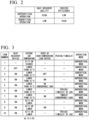
- FIG. 2 shows characteristics of the supercritical operation and the subcritical operation according to the embodiment.
- the applicant has found the characteristics shown in FIG. 2 after performing verification and desk calculation using the exhaust heat recovery freezer system 1 shown in FIG. 1 as an example. That is, when the freezer 10 is in the supercritical operation, the efficiency of the freezer 10 alone deteriorates, but the overall efficiency of the freezer 10 and the high-temperature load device 30 in their entirety rises. In contrast, when the freezer 10 is in the subcritical operation, the operation efficiency of the freezer 10 alone can be improved, but the overall efficiency of the exhaust heat recovery freezer system 1 (the freezer 10 and the high-temperature load device 30 in their entirety) deteriorates.
- efficiency indicates consumption energy consumed by the exhaust heat recovery freezer system 1. Through trial calculation, it has been confirmed that the total annual energy consumption of the freezer 10 and the high-temperature load device 30 can be reduced by several percent by performing the operation of the freezer 10 while switching between the supercritical operation and the subcritical operation under predetermined conditions.
- the operation mode decision unit 44 may determine that necessity of heat recovery is high when at least one of the outside air temperature, the load state of the high-temperature load device 30 (whether the load is large or small), and the period or the timeslot satisfies the predetermined conditions.
- FIG. 3 shows an example of criteria for such determination.
- FIG. 3 is a diagram illustrating an example of conditions for switching between the supercritical operation and the subcritical operation according to the embodiment. In the table of FIG. 3 , "-" denotes that the corresponding condition is not taken into consideration. In addition, the following (1) to (10) respectively correspond to the item numbers 1 to 10 in FIG. 3 .
- the exhaust heat recovery device 20 It is possible to judge whether the exhaust heat recovery device 20 is working or at a stop based on a signal indicating the working state of the exhaust heat recovery device 20 (for example, detection values of various kinds of sensors measuring the rotation frequency of the pump 22, the flow rate of water flowing in piping 23, the flow speed, the temperature, the pressure, and the like) acquired by the signal acquisition unit 41 and the working log of the exhaust heat recovery device 20 recorded in the storage unit 46.
- a signal indicating the working state of the exhaust heat recovery device 20 for example, detection values of various kinds of sensors measuring the rotation frequency of the pump 22, the flow rate of water flowing in piping 23, the flow speed, the temperature, the pressure, and the like
- the operation mode decision unit 44 may judge that the exhaust heat recovery device 20 is at a stop.
- the latest record of the records of the working log indicates "stop"
- the operation mode decision unit 44 may judge that the exhaust heat recovery device 20 is at a stop.
- the operation mode decision unit 44 decides that the operation mode is set to the subcritical operation.
- the operation mode decision unit 44 may judge that the high-temperature load device 30 is at a stop.
- the operation mode decision unit 44 may decide that the operation mode is set to the supercritical operation. For example, in a case in which heating is used throughout the year in a cold region or the like, when the exhaust heat recovery device 20 and the high-temperature load device 30 are in a working state, even if the efficiency of the freezer 10 alone has deteriorated, a heating load of the air conditioner may decrease and the efficiency of the exhaust heat recovery freezer system 1 in its entirety may be improved (necessity of heat recovery is high) by raising heat recovery ability through the supercritical operation and supplying more heat to the high-temperature load device 30.
- the conditions for switching as in (4) can be set.
- the operation mode decision unit 44 may judge that the exhaust heat recovery device 20 is working.
- the operation mode decision unit 44 may judge that the exhaust heat recovery device 20 is working.
- the operation mode decision unit 44 may judge that the high-temperature load device 30 is working.
- the operation mode decision unit 44 may decide that the operation mode is set to the supercritical operation. For example, even when the air conditioner is performing a heating operation as the high-temperature load device 30, if the air-conditioning load is small, the efficiency of the exhaust heat recovery freezer system 1 may be improved (necessity of heat recovery is low) by prioritizing the efficiency of the freezer 10 alone.
- the conditions for switching the operation mode to the supercritical operation may be set only when the outside air temperature is lower than X1°C, the exhaust heat recovery device 20 is working, and the high-temperature load device 30 is working with a considerable load, that is, under conditions in which necessity of heat recovery becomes high.
- the operation mode decision unit 44 may judge that the load on the high-temperature load device 30 is large.
- the operation mode decision unit 44 may judge that the load on the high-temperature load device 30 is large.
- the operation mode decision unit 44 may judge that the load on the high-temperature load device 30 is large.
- the operation mode decision unit 44 may decide that the operation mode is set to the supercritical operation. For example, a period during which heating is used (winter, or fall or spring depending on the region) is set for the period.
- a period during which heating is used is set for the period.
- a timeslot in which the high-temperature load device 30 is working (for example, 9:00 to 20:00) may be set as the conditions for switching in addition to the period during which the high-temperature load device 30 is used.
- only a timeslot in which necessity of heat recovery becomes high may be set without setting a use period.
- the operation mode decision unit 44 decides that the operation mode is set to the supercritical operation. Otherwise, it is decided that the operation mode is set to the subcritical operation.
- the operation mode decision unit 44 may decide that the operation mode is set to the supercritical operation. For example, it is assumed that a timeslot of using hot water of the water heater is concentrated during 10:00 to 15:00. At this timeslot, the efficiency of the exhaust heat recovery freezer system 1 in its entirety is improved (necessity of heat recovery is high) by performing exhaust heat recovery and providing recovered heat to the water heater. However, when the load on the water heater is not so high at other timeslots, it is meaningless to perform exhaust heat recovery.
- the operation mode decision unit 44 decides that the operation mode is set to the supercritical operation when the outside air temperature is lower than X1°C, the exhaust heat recovery device 20 and the high-temperature load device 30 are working, and it is the timeslot in which the load on the high-temperature load device 30 becomes large (10:00 to 15:00). Otherwise, it may be decided that the operation mode is set to the subcritical operation.
- the operation mode decision unit 44 may decide that the operation mode is set to the supercritical operation.
- X2°C ⁇ X1°C is established.
- X2°C is a temperature at which the heating load on the air conditioner becomes high, in other words, an outside air temperature at which necessity of heat recovery becomes high.
- the operation mode decision unit 44 may decide that the operation mode is set to the supercritical operation on condition that the outside air temperature is X2°C or lower and the exhaust heat recovery device 20 is working. Otherwise, it may be decided that the operation mode is set to the subcritical operation.
- the operation mode decision unit 44 decides that the operation mode is set to the supercritical operation. For example, even if the outside air temperature is X2°C or lower at which the heating load on the air conditioner becomes high, since the air conditioner is not working if the store is not open for business, the overall efficiency of the exhaust heat recovery freezer system 1 is improved (necessity of heat recovery is low) by improving the efficiency of the freezer 10 alone at the timeslot in which the air conditioner is not working.
- the operation mode decision unit 44 may decide that the operation mode is set to the supercritical operation. Otherwise, it may be decided that the operation mode is set to the subcritical operation.
- the operation mode decision unit 44 may decide that the operation mode is set to the supercritical operation. If not, it may be decided that the subcritical operation is set. For example, a heating operation of the air conditioner is presumed as a load, winter is set as a period, and the business hours of the store are set as a timeslot (necessity of heat recovery is high).
- the operation mode decision unit 44 may decide that the operation mode is set to the supercritical operation. Otherwise, it is decided that the operation mode is set to the subcritical operation.
- the conditions for switching between the supercritical operation and the subcritical operation in the item numbers 1 to 10 described above are examples and are not limited thereto.
- the conditions for switching may be set such that it is decided to set the operation mode to the supercritical operation.
- the conditions for switching the operation mode to the supercritical operation when the outside air temperature is lower than X1°C (or is X2°C or lower) and it is a predetermined period and a predetermined timeslot, or the conditions for switching the operation mode to the supercritical operation when the outside air temperature is simply lower than X1°C (or is X2°C or lower) may be set.
- FIG. 4 is a flowchart illustrating an example of switching control according to the embodiment.
- a user sets conditions for switching between the supercritical operation and the subcritical operation. For example, a user sets conditions for the item numbers 1, 2, 5, and 9 in FIG. 3 .
- the setting reception unit 42 receives a setting of the conditions for switching and records the set conditions for switching in the storage unit 46 (Step S1).
- the operation mode decision unit 44 acquires the outside air temperature (Step S2). For example, the signal acquisition unit 41 acquires the outside air temperature detected by the temperature sensor tho3 from hour to hour and records the acquired outside air temperature together with the time in the storage unit 46. The operation mode decision unit 44 acquires the outside air temperature recorded in the storage unit 46.
- the operation mode decision unit 44 acquires the working state of the exhaust heat recovery device 20 (Step S3).
- the signal acquisition unit 41 acquires a signal indicating the working state of the exhaust heat recovery device 20 from hour to hour, such as a measurement value including the rotation frequency of the pump 22, the temperature of water flowing in the piping 23, or the like, and records these together with the time in the storage unit 46.
- the operation mode decision unit 44 acquires a signal indicating the working state of the exhaust heat recovery device 20 recorded in the storage unit 46.
- the operation mode decision unit 44 acquires the latest record of the working log recorded in the storage unit 46.
- the operation mode decision unit 44 acquires the working state or the load state of the high-temperature load device 30 (Step S4).
- the signal acquisition unit 41 acquires a signal indicating the working state of the high-temperature load device 30 from hour to hour, such as the rotation frequency of the compressor or the water level of the water storage tank in the high-temperature load device 30 or a signal which can be used for estimation of the load state and records these together with the time in the storage unit 46.
- a prediction value of the load on the high-temperature load device 30 predicted by means of a predetermined predictive model in advance (for example, a load prediction value for each daily timeslot during a predetermined period of time) may be recorded.
- the operation mode decision unit 44 acquires a signal indicating the working state or the load state of the high-temperature load device 30 recorded in the storage unit 46 and the prediction value of the load.
- the order of processing of Steps S2 to S4 can be arbitrarily changed, and Steps S2 to S4 may be simultaneously performed in parallel.
- the operation mode decision unit 44 decides the operation mode (Step S5).
- the operation mode decision unit 44 determines necessity of heat recovery and decides the operation mode on the basis of the signals acquired in Steps S2 to 4 and the conditions for switching set in Step S 1. For example, when the outside air temperature is X1°C or higher, the operation mode decision unit 44 decides that the operation mode is set to the supercritical operation (the conditions for switching of the item number 1). For example, when a signal indicating that the outside air temperature is lower than X1°C and the exhaust heat recovery device 20 is at a stop is acquired, the operation mode decision unit 44 decides that the operation mode is set to the subcritical operation (the conditions for switching of the item number 2).
- the operation mode decision unit 44 determines that necessity of heat recovery is high and decides that the operation mode is set to the supercritical operation. When none of the conditions for switching of the item number 5 and the item number 9 is satisfied, the operation mode decision unit 44 determines that necessity of heat recovery is low and decides that the operation mode is set to the subcritical operation.
- the operation mode decision unit 44 may judge that the high-temperature load device 30 is working with a high load, and if the compressor in the high-temperature load device 30 is in operation with a rotation frequency equal to or higher than a predetermined value, it may be judged that the high-temperature load device 30 is working with a high load.
- the operation mode decision unit 44 determines that necessity of heat exchange is high.
- the item number 9 when the exhaust heat recovery device 20 and the high-temperature load device 30 are working and the outside air temperature is X2°C or lower, the operation mode decision unit 44 determines that necessity of heat exchange is high.
- the item number 6 if the exhaust heat recovery device 20 is working, the outside air temperature is lower than X1°C, and it is a predetermined period and/or timeslot, the operation mode decision unit 44 determines that necessity of heat exchange is high.
- the operation mode decision unit 44 outputs the decided operation mode to the freezer control unit 45.
- the freezer control unit 45 causes the freezer 10 to operate in accordance with the decision of the operation mode decision unit 44.
- the freezer control unit 45 instructs the two-stage compressor 11 to perform the supercritical operation. Accordingly, the high-pressure supercritical operation in which a refrigerant is in the supercritical state on the high-pressure side of the refrigerant circuit is executed (Step S6).
- the freezer control unit 45 instructs the two-stage compressor 11 to perform the subcritical operation. Accordingly, the high-pressure subcritical operation in which a refrigerant is in the subcritical state on the high-pressure side of the refrigerant circuit is executed (Step S7).
- the operation of the freezer 10 is controlled to be either the supercritical operation or the subcritical operation on the basis of a setting of the conditions for switching set such that the overall efficiency of the freezer 10 and the high-temperature load device 30 is improved ( FIG. 3 ).
- the efficiency of the exhaust heat recovery freezer system 1 can be improved by switching between the high-pressure supercritical operation and the high-pressure subcritical operation of the freezer in accordance with the efficiency of the exhaust heat recovery freezer system 1 in its entirety.
- FIG. 5 is a diagram illustrating an example of a hardware constitution of a system controller according to the embodiment.
- a computer 900 includes a CPU 901, a main storage device 902, an auxiliary storage device 903, an input/output interface 904, and a communication interface 905.
- the system controller 40 is mounted in the computer 900. Further, each of the functions described above is stored in the auxiliary storage device 903 in a form of a program.
- the CPU 901 reads the program from the auxiliary storage device 903 and develops it in the main storage device 902, and the foregoing processing is executed in accordance with the program.
- the CPU 901 secures a storage domain in the main storage device 902 in accordance with the program.
- the CPU 901 secures the storage domain for storing data being processed in the auxiliary storage device 903 in accordance with the program.
- Processing by each of the functional units may be performed by recording a program for realizing all or some of the functions of the system controller 40 in a computer readable recording medium, causing a computer system to read and execute the program recorded in this recording medium.
- a computer system includes hardware such as an OS and peripheral equipment.
- a computer system also includes a homepage-provided environment (or a display environment).
- a computer readable recording medium indicates a storage device including a portable medium such as a CD, a DVD, or a USB, and a hard disk built into the computer system.
- the computer 900 when this program is distributed in the computer 900 through a communication line, the computer 900 which has received the distribution may develop the program in the main storage device 902 to execute the foregoing processing.
- the foregoing program may be a program for realizing a part of the functions described above or may be a program capable of realizing the functions described above in combination with a program which has already been recorded in the computer system.
- constituent elements in the foregoing embodiment can be suitably replaced with known constituent elements within a range not departing from the gist of the present invention.
- technical scope of this invention is not limited to the foregoing embodiment, and various changes can be added thereto within a range not departing from the gist of the present invention.
- control device The control device, the exhaust heat recovery freezer system, the control method, and the program according to each embodiment are ascertained as follows, for example.
- the freezer can switch between the high-pressure supercritical operation and the high-pressure subcritical operation in accordance with the overall efficiency of the freezer 10 and the high-temperature load device 30. Accordingly, the foregoing overall efficiency can be improved.
- control device is the control device according to (1), in which the operation mode decision unit 44 decides to perform the supercritical operation when the outside air temperature becomes equal to or lower than a predetermined temperature (X2°C or lower) at which the load of the device (high-temperature load device 30) is estimated to be large (for example, the item number 8 in FIG. 3 ).
- a predetermined temperature X2°C or lower
- the heat recovery ability of the exhaust heat recovery device 20 is raised and the operation load of the high-temperature load device 30 is reduced by switching the operation of the freezer 10 to the supercritical operation. Accordingly, the overall efficiency of the freezer 10 and the high-temperature load device 30 can be improved.
- control device is the control device according to (1) to (2), in which the operation mode decision unit 44 decides to perform the supercritical operation during a predetermined period and/or a predetermined timeslot in which the load of the device (high-temperature load device 30) becomes large (for example, the item number 6 in FIG. 3 ).
- the heat recovery ability of the exhaust heat recovery device 20 is raised and the operation load of the high-temperature load device 30 is reduced by switching the operation of the freezer 10 to the supercritical operation. Accordingly, the overall efficiency of the freezer 10 and the high-temperature load device 30 can be improved.
- control device is the control device according to (1) to (3), in which the operation mode decision unit 44 judges whether or not necessity of the heat recovery is considerable (judges whether or not the load is considerable) on the basis of a signal indicating the operation state of the high-temperature load device 30 that is a supply destination of heat which has been subjected to heat recovery, and decides to perform the supercritical operation when it is judged that necessity of the heat recovery is high (the load is large) (for example, the item number 5 in FIG. 3 ).
- the operation of the freezer 10 is switched to the supercritical operation. Accordingly, the heat recovery ability of the exhaust heat recovery device 20 can be raised, the operation load of the high-temperature load device 30 can be reduced, and the overall efficiency of the freezer 10 and the high-temperature load device 30 can be improved.
- control device is the control device according to (1) to (4), in which the operation mode decision unit 44 judges whether or not the exhaust heat recovery device 20, which recovers heat through heat exchange with a refrigerant circulating in the refrigerant circuit between the compressor and the gas cooler in the refrigerant circuit and supplies the recovered heat to the load device, is working, and decides to perform the subcritical operation when the exhaust heat recovery device 20 is not working.
- the efficiency of the freezer 10 can be improved and the overall efficiency of the freezer 10 and the high-temperature load device 30 can be improved by performing the subcritical operation.
- the exhaust heat recovery freezer system 1 includes the freezer 10 that has a refrigerant circuit including the compressor (two-stage compressor 11) and the gas cooler 12; the exhaust heat recovery device 20 that recovers heat through heat exchange with a refrigerant circulating in the refrigerant circuit between the compressor and the gas cooler in the refrigerant circuit and supplies the recovered heat to the high-temperature load device; and the control device (system controller 40) according to any one of (1) to (5).
- the freezer can switch between the high-pressure supercritical operation and the high-pressure subcritical operation in accordance with the overall efficiency of the freezer 10 and the high-temperature load device 30. Accordingly, the foregoing overall efficiency can be improved.
- the exhaust heat recovery freezer system 1 is the exhaust heat recovery freezer system according to (6), in which the control device (system controller 40) further includes the exhaust heat recovery device control unit 43 for controlling working and stopping of the exhaust heat recovery device 20.
- the control method includes the step of deciding, in accordance with necessity of heat recovery from a refrigerant circulating in the refrigerant circuit or in accordance with the load state of the device supplying heat of a refrigerant circulating in the refrigerant circuit, which operation of the supercritical operation in which the high pressure in the refrigerant circuit is in the supercritical state and the subcritical operation in which the high pressure is in the subcritical state is to be performed; and the step of controlling the refrigerant circuit to be operated in either the supercritical operation or the critical operation on the basis of decision in the step of deciding an operation.
- the program causes a computer to execute the step of deciding, in accordance with necessity of heat recovery from a refrigerant circulating in the refrigerant circuit or in accordance with the load state of the device supplying heat of a refrigerant circulating in the refrigerant circuit, which operation of the supercritical operation in which the high pressure in the refrigerant circuit is in the supercritical state and the subcritical operation in which the high pressure is in the subcritical state is to be performed; and the step of controlling the refrigerant circuit to be operated in either the supercritical operation or the critical operation on the basis of decision in the step of deciding an operation.
Landscapes
- Engineering & Computer Science (AREA)
- Physics & Mathematics (AREA)
- Thermal Sciences (AREA)
- Mechanical Engineering (AREA)
- General Engineering & Computer Science (AREA)
- Chemical & Material Sciences (AREA)
- Combustion & Propulsion (AREA)
- Computer Hardware Design (AREA)
- Chemical Kinetics & Catalysis (AREA)
- Air Conditioning Control Device (AREA)
Abstract
Description
- The present invention relates to a control device, an exhaust heat recovery freezer system, a control method, and a program. Priority is claimed on
Japanese Patent Application No. 2022-040662, filed March 15, 2022 -
Patent Document 1 discloses control in which heat discharged from a freezer using a CO2 refrigerant when a show case in a store is cooled using the freezer is utilized for hot water or heating. Specifically,Patent Document 1 discloses control in which a part of a refrigerant emitted by a compressor is supplied to a radiator unit and utilized for heating and water which has been heat-exchanged in a condenser is utilized as hot water. In addition,Patent Document 2 discloses an air conditioner using a CO2 refrigerant with a freezing cycle in which a high pressure is in a supercritical state when a cooling operation is performed in normal environmental conditions and the high pressure is in a subcritical state in a state in which the outside air temperature is low. -
- [Patent Document 1]
Japanese Unexamined Patent Application, First Publication No. 2020-118354 - [Patent Document 2]
Japanese Unexamined Patent Application, First Publication No. 2014-89042 - There is a demand for a method for improving combined efficiency of both a load-side device (an air conditioner, a water heater, or the like), which utilizes exhaust heat from a freezer, and the freezer.
- Hence, an object of this invention is to provide a control device, an exhaust heat recovery freezer system, a control method, and a program capable of resolving the problems described above.
- According to an aspect of the present disclosure, a control device includes an operation mode decision unit that decides, in accordance with necessity of heat recovery from a refrigerant circulating in a refrigerant circuit, which operation of a supercritical operation in which a high pressure in the refrigerant circuit is in a supercritical state and a subcritical operation in which the high pressure is in a subcritical state is to be performed; and a freezer control unit that controls the refrigerant circuit to be operated in either the supercritical operation or the subcritical operation on the basis of decision of the operation mode decision unit.
- According to another aspect of the present disclosure, an exhaust heat recovery freezer system includes a freezer that has a refrigerant circuit including a compressor, a gas cooler, an expansion valve, and an evaporator; an exhaust heat recovery device that recovers heat through heat exchange with a refrigerant circulating in the refrigerant circuit between the compressor and the gas cooler in the refrigerant circuit and supplies the recovered heat to a load device; and the foregoing control device.
- According to another aspect of the present disclosure, a control method includes a step of deciding, in accordance with necessity of heat recovery from a refrigerant circulating in a refrigerant circuit, which operation of a supercritical operation in which a high pressure in the refrigerant circuit is in a supercritical state and a subcritical operation in which the high pressure is in a subcritical state is to be performed; and a step of controlling the refrigerant circuit to be operated in either the supercritical operation or the subcritical operation on the basis of decision in the step of deciding an operation.
- According to another aspect of the present disclosure, a program causes a computer to execute a step of deciding, in accordance with necessity of heat recovery from a refrigerant circulating in a refrigerant circuit, which operation of a supercritical operation in which a high pressure in the refrigerant circuit is in a supercritical state and a subcritical operation in which the high pressure is in a subcritical state is to be performed; and a step of controlling the refrigerant circuit to be operated in either the supercritical operation or the subcritical operation on the basis of decision in the step of deciding an operation.
- According to the control device, the exhaust heat recovery freezer system, the control method, and the program of the present disclosure, it is possible to improve overall efficiency of both a load device, which utilizes exhaust heat of a freezer, and the freezer.
-
-
FIG. 1 is a diagram illustrating an example of an exhaust heat recovery freezer system according to an embodiment. -
FIG. 2 is a diagram illustrating characteristics of a high-pressure supercritical operation and a high-pressure subcritical operation according to the embodiment. -
FIG. 3 is a diagram illustrating an example of conditions for switching according to the embodiment. -
FIG. 4 is a flowchart illustrating an example of switching control according to the embodiment. -
FIG. 5 is a diagram illustrating an example of a hardware constitution of a system controller according to the embodiment. - Hereinafter, an exhaust heat recovery freezer system according to an embodiment of the present disclosure will be described with reference to
FIGS. 1 to 5 . -
FIG. 1 is a diagram illustrating an example of an exhaust heat recovery freezer system according to the embodiment. - An exhaust heat
recovery freezer system 1 is a system in which heat discharged by afreezer 10 performing a cooling operation is recovered by an exhaustheat recovery device 20 and the recovered heat is supplied to a warming cycle of a high-temperature load device 30. For example, the exhaust heatrecovery freezer system 1 is used in supermarkets or the like, in which thefreezer 10 refrigerates or freezes food and exhaust heat therefrom is recovered by the exhaustheat recovery device 20 and utilized for heating of the store or in a water heater. In the exhaust heatrecovery freezer system 1, CO2 is used as a refrigerant. A CO2 refrigerant is in a supercritical state within an ordinary temperature range at approximately 31°C. From a viewpoint of efficiency of the exhaust heatrecovery freezer system 1 in its entirety instead of efficiency of thefreezer 10 alone, the exhaust heatrecovery freezer system 1 determines necessity of heat recovery by the exhaustheat recovery device 20 and operates with a high pressure in thefreezer 10 in a supercritical state or a subcritical state in accordance with the necessity thereof. - As shown in
FIG. 1 , the exhaust heatrecovery freezer system 1 includes thefreezer 10, the exhaustheat recovery device 20, the high-temperature load device 30, a low-temperature load device 31 (for example, a refrigerating show case or a freezing show case in a supermarket), and asystem controller 40. Thefreezer 10 includes a two-stage compressor 11, agas cooler 12, afirst expansion valve 13a, areceiver 14, anaccumulator 16, amain piping 17 connecting these to the low-temperature load device 31, apiping 18 connecting a gas-phase portion of thereceiver 14 to an emission side of a low stage-side compressor 11b of a high stage-side compressor 11a and the low stage-side compressor 11b included in the two-stage compressor 11, avalve 18a controlling a flow rate of the refrigerant flowing in thepiping 18, afan 19 provided in thegas cooler 12, and temperature sensors tho 1 to tho3. Thetemperature sensor tho 1 is provided on the emission side of the two-stage compressor 11 and an entrance side of aheat exchanger 21, and the temperature sensor tho2 is provided on an exit side of theheat exchanger 21 and the entrance side of thegas cooler 12. The exit side and the entrance side are an exit side and an entrance side in a flowing direction of the refrigerant. In addition, the temperature sensor tho3 is provided at a position where an outside air temperature can be measured. The low-temperature load device 31 is constituted of asecond expansion valve 13b and anevaporator 15 and is connected to a low pressure side of thefreezer 10. - The
heat exchanger 21 of the exhaustheat recovery device 20 is connected (inserted) between the two-stage compressor 11 and thegas cooler 12, and the CO2 refrigerant of thefreezer 10 flows in theheat exchanger 21. The exhaustheat recovery device 20 includes theheat exchanger 21 for exhaust heat recovery, apump 22, and apiping 23 connecting these to the high-temperature load device 30. For example, the high-temperature load device 30 is an air conditioner, a water heater, or the like in a store. In theheat exchanger 21, heat exchange is performed between the CO2 refrigerant of thefreezer 10 and the refrigerant (for example, water) of the exhaustheat recovery device 20. In the exhaustheat recovery device 20, warm water which has been warmed through heat exchange in theheat exchanger 21 circulates in thepiping 23 by driving of thepump 22, and for example, exhaust heat from thefreezer 10 is supplied to the high-temperature load device 30 via a heat exchanger (not shown) provided in the high-temperature load device 30. Since the refrigerant does not circulate in thepiping 23 when thepump 22 is at a stop, exhaust heat is not recovered by the exhaustheat recovery device 20. - In the
freezer 10, the two-stage compressor 11 emits a high-pressure refrigerant compressed by the high stage-side compressor 11a and the low stage-side compressor 11b. In more detail, a suction side of the low stage-side compressor 11b is connected to theaccumulator 16, and the low stage-side compressor 11b suctions and compresses the refrigerant (gas) separated by theaccumulator 16. The low stage-side compressor 11b emits the compressed refrigerant to the suction side of the high stage-side compressor 11a. The refrigerant is supplied from the gas-phase portion of thereceiver 14 to the suction side of the high stage-side compressor 11a through the piping 18 (injection circuit). The high stage-side compressor 11a suctions and compresses these refrigerants. The compressed refrigerant is supplied to theheat exchanger 21 for exhaust heat recovery. As described above, in theheat exchanger 21, heat of the high-temperature/high-pressure CO2 refrigerant is recovered by the refrigerant (water) of the exhaustheat recovery device 20 and is supplied to the high-temperature load device 30. The CO2 refrigerant which has passed through theheat exchanger 21 is subjected to heat dissipation through heat exchange in thegas cooler 12 with air sent by thefan 19 and is condensed and liquefied. The condensed refrigerant is subjected to pressure reduction and expansion by thefirst expansion valve 13a and is supplied to thereceiver 14. In thereceiver 14, a two-phase refrigerant of gas and liquid is present in a mixed manner. A part (gas-phase portion) of the refrigerant present in thereceiver 14 branches to thepiping 18 as described above and is supplied to the two-stage compressor 11. The liquid-phase refrigerant flows out from thereceiver 14, is subjected to additional pressure reduction by the second expansion valve, and is then supplied to theevaporator 15. The CO2 refrigerant supplied to theevaporator 15 absorbs heat of the low-temperature load device 31 (for example, a show case for refrigeration or a show case for freezing in a store), is gasified, and cools the low-temperature load device 31. The CO2 refrigerant gasified by theevaporator 15 is supplied to theaccumulator 16. The CO2 refrigerant is separated into gas and liquid by theaccumulator 16, and the gas refrigerant is suctioned into the low stage-side compressor 11b. The refrigerant is compressed by the low stage-side compressor 11b and the high stage-side compressor 11a and circulates through the foregoing path again. - The exhaust heat
recovery freezer system 1 shown inFIG. 1 is a schematic basic constitution and may further include other constituent elements. InFIG. 1 , the exhaustheat recovery device 20 has only oneheat exchanger 21, but the exhaustheat recovery device 20 may include two ormore heat exchangers 21. In this case, all or some of the plurality ofheat exchangers 21 may be connected to (inserted into) a refrigerant circuit of thefreezer 10. In addition, a plurality of exhaustheat recovery devices 20 may be present, and theheat exchanger 21 provided in each exhaustheat recovery device 20 may be connected to the refrigerant circuit of thefreezer 10. - The
system controller 40 controls thefreezer 10 and the exhaustheat recovery device 20. Thesystem controller 40 includes asignal acquisition unit 41, asetting reception unit 42, an exhaust heat recoverydevice control unit 43, an operationmode decision unit 44, afreezer control unit 45, and astorage unit 46. In addition, thesystem controller 40 has a timer, which can recognize the current date and time. - The
signal acquisition unit 41 acquires the temperature detected by the temperature sensors tho1 to tho3, a signal indicating a working state of the exhaustheat recovery device 20, and a signal indicating an operation state (a working state or a load state) of the high-temperature load device 30. Thesignal acquisition unit 41 records various kinds of acquired signals in thestorage unit 46. - The
setting reception unit 42 receives an input of various kinds of settings made by a user. For example, thesetting reception unit 42 receives a setting for working (ON) or stopping (OFF) of the exhaustheat recovery device 20 and outputs the setting to the exhaust heat recoverydevice control unit 43. In addition, regarding the operation of thefreezer 10, thesetting reception unit 42 receives a setting of conditions for switching between an operation in which the high pressure is in the supercritical state (which may hereinafter be referred to as a supercritical operation) and an operation in which the high pressure is in the subcritical state (which may hereinafter be referred to as a subcritical operation) and records the received setting of the conditions for switching in thestorage unit 46. - The exhaust heat recovery
device control unit 43 controls working (ON) and stopping (OFF) of the exhaustheat recovery device 20. For example, when a user performs setting for causing the exhaustheat recovery device 20 to work, the exhaust heat recoverydevice control unit 43 acquires the setting through thesetting reception unit 42 and causes the exhaustheat recovery device 20 to work by starting thepump 22, or the like. When a user performs setting for causing the exhaustheat recovery device 20 to stop, the exhaust heat recoverydevice control unit 43 acquires the setting through thesetting reception unit 42 and causes the exhaustheat recovery device 20 to stop by stopping thepump 22, or the like. When the exhaustheat recovery device 20 is caused to work or stop, the exhaust heat recoverydevice control unit 43 records the time at which the control is performed and the executed operation of either working or stopping in thestorage unit 46 as a working log. - The operation
mode decision unit 44 determines necessity of exhaust heat recovery and decides the operation mode of thefreezer 10 on the basis of the outside air temperature acquired by thesignal acquisition unit 41, the working state of the exhaustheat recovery device 20, the load state of the high-temperature load device 30, and the setting of the conditions for switching recorded in thestorage unit 46 by thesetting reception unit 42. The operation mode is either the supercritical operation or the subcritical operation. For example, when the efficiency of the exhaust heatrecovery freezer system 1 in its entirety is improved by intensifying exhaust heat recovery, the operationmode decision unit 44 determines that necessity of exhaust heat recovery is high. If not, it is determined that necessity of exhaust heat recovery is low. When necessity of exhaust heat recovery is high, the operationmode decision unit 44 decides that the supercritical operation is performed, and when necessity of exhaust heat recovery is not high, it is decided that the subcritical operation is performed. - The
freezer control unit 45 causes thefreezer 10 to operate in the operation mode decided by the operationmode decision unit 44. For example, the two-stage compressor 11 is constituted to operate with a rotation frequency in which the pressure on the high-pressure side is in the supercritical state when instructed to perform the supercritical operation and to operate with a rotation frequency in which the pressure on the high-pressure side is in the subcritical state when instructed to perform the subcritical operation. When the operationmode decision unit 44 decides that the supercritical operation is performed, thefreezer control unit 45 instructs the two-stage compressor 11 to perform the supercritical operation. When the operationmode decision unit 44 decides that the subcritical operation is performed, thefreezer control unit 45 instructs the two-stage compressor 11 to perform the subcritical operation. Above this, thefreezer control unit 45 performs various kinds of control related to thefreezer 10, but description related to functions other than switching of the operation mode will be omitted. Thestorage unit 46 stores signals acquired by thesignal acquisition unit 41 and the setting of the conditions for switching received by thesetting reception unit 42. -
FIG. 2 shows characteristics of the supercritical operation and the subcritical operation according to the embodiment. The applicant has found the characteristics shown inFIG. 2 after performing verification and desk calculation using the exhaust heatrecovery freezer system 1 shown inFIG. 1 as an example. That is, when thefreezer 10 is in the supercritical operation, the efficiency of thefreezer 10 alone deteriorates, but the overall efficiency of thefreezer 10 and the high-temperature load device 30 in their entirety rises. In contrast, when thefreezer 10 is in the subcritical operation, the operation efficiency of thefreezer 10 alone can be improved, but the overall efficiency of the exhaust heat recovery freezer system 1 (thefreezer 10 and the high-temperature load device 30 in their entirety) deteriorates. Here, for example, efficiency indicates consumption energy consumed by the exhaust heatrecovery freezer system 1. Through trial calculation, it has been confirmed that the total annual energy consumption of thefreezer 10 and the high-temperature load device 30 can be reduced by several percent by performing the operation of thefreezer 10 while switching between the supercritical operation and the subcritical operation under predetermined conditions. - The operation
mode decision unit 44 may determine that necessity of heat recovery is high when at least one of the outside air temperature, the load state of the high-temperature load device 30 (whether the load is large or small), and the period or the timeslot satisfies the predetermined conditions.FIG. 3 shows an example of criteria for such determination.FIG. 3 is a diagram illustrating an example of conditions for switching between the supercritical operation and the subcritical operation according to the embodiment. In the table ofFIG. 3 , "-" denotes that the corresponding condition is not taken into consideration. In addition, the following (1) to (10) respectively correspond to theitem numbers 1 to 10 inFIG. 3 . - (1) When a show case for refrigeration or freezing in a store is cooled by the
freezer 10, regardless of the working states of the exhaustheat recovery device 20 and the high-temperature load device 30, if operation is performed in an environment in which the outside air temperature is X1°C (for example, 25°C) or higher, the high pressure is in the supercritical state. When the outside air temperature detected by the temperature sensor tho3 and acquired by thesignal acquisition unit 41 becomes X1°C or higher, the operationmode decision unit 44 decides that the operation mode is set to the supercritical operation. - Hereinafter, a case in which the outside air temperature is lower than X1°C will be examined.
- (2) When the exhaust
heat recovery device 20 is not working (when thepump 22 is at a stop), exhaust heat of thefreezer 10 is not supplied to the high-temperature load device 30. In this case, since the efficiency of the exhaust heatrecovery freezer system 1 in its entirety is improved by improving the efficiency of thefreezer 10 alone, necessity of heat recovery is low. Therefore, when the outside air temperature is lower than X1°C and the exhaustheat recovery device 20 is not working, the operationmode decision unit 44 decides that the operation mode is set to the subcritical operation. - It is possible to judge whether the exhaust
heat recovery device 20 is working or at a stop based on a signal indicating the working state of the exhaust heat recovery device 20 (for example, detection values of various kinds of sensors measuring the rotation frequency of thepump 22, the flow rate of water flowing in piping 23, the flow speed, the temperature, the pressure, and the like) acquired by thesignal acquisition unit 41 and the working log of the exhaustheat recovery device 20 recorded in thestorage unit 46. For example, if the rotation frequency of thepump 22 is equal to or lower than a predetermined value (for example, 0 rpm) or the temperature of water is lower than a predetermined value, the operationmode decision unit 44 may judge that the exhaustheat recovery device 20 is at a stop. When the latest record of the records of the working log indicates "stop", the operationmode decision unit 44 may judge that the exhaustheat recovery device 20 is at a stop. - (3) When the high-
temperature load device 30 is not working as well, the efficiency of the exhaust heatrecovery freezer system 1 is improved by improving the efficiency of thefreezer 10 alone (necessity of heat recovery is low). Therefore, when the outside air temperature is lower than X1°C and the high-temperature load device 30 is not working, the operationmode decision unit 44 decides that the operation mode is set to the subcritical operation. - It is possible to judge whether the high-
temperature load device 30 is working or at a stop based on a signal indicating the working state of the high-temperature load device 30 (for example, detection values detected by various kinds of sensors included in an air conditioner or a water heater) acquired by thesignal acquisition unit 41. For example, if the rotation frequency of a compressor provided in an air conditioner or a water heater is equal to or lower than a predetermined value (for example, 0 rps) or the refrigerant temperature is lower than a predetermined value, the operationmode decision unit 44 may judge that the high-temperature load device 30 is at a stop. - (4) On condition that the outside air temperature is lower than X1°C and the exhaust
heat recovery device 20 and the high-temperature load device 30 are working, the operationmode decision unit 44 may decide that the operation mode is set to the supercritical operation. For example, in a case in which heating is used throughout the year in a cold region or the like, when the exhaustheat recovery device 20 and the high-temperature load device 30 are in a working state, even if the efficiency of thefreezer 10 alone has deteriorated, a heating load of the air conditioner may decrease and the efficiency of the exhaust heatrecovery freezer system 1 in its entirety may be improved (necessity of heat recovery is high) by raising heat recovery ability through the supercritical operation and supplying more heat to the high-temperature load device 30. For example, when the outside air temperature is lower than X1°C, if the efficiency in its entirety is improved by performing the supercritical operation, the conditions for switching as in (4) (the supercritical operation is performed when the exhaustheat recovery device 20 and the high-temperature load device 30 are working at an outside air temperature lower than X1°C) can be set. - Regarding judgment whether or not the exhaust
heat recovery device 20 and the high-temperature load device 30 are working, for example, if the rotation frequency of thepump 22 is equal to or higher than a predetermined value or the temperature of water flowing in the piping 23 is higher than a predetermined value, the operationmode decision unit 44 may judge that the exhaustheat recovery device 20 is working. When the latest record of the records of the working log indicates working, the operationmode decision unit 44 may judge that the exhaustheat recovery device 20 is working. For example, when the rotation frequency of the compressor provided in the air conditioner or the water heater is equal to or higher than a predetermined value or when the refrigerant temperature is equal to or higher than a predetermined value, the operationmode decision unit 44 may judge that the high-temperature load device 30 is working. - (5) While being in the case of the
item number 4, and on condition that the load on the high-temperature load device 30 is large, the operationmode decision unit 44 may decide that the operation mode is set to the supercritical operation. For example, even when the air conditioner is performing a heating operation as the high-temperature load device 30, if the air-conditioning load is small, the efficiency of the exhaust heatrecovery freezer system 1 may be improved (necessity of heat recovery is low) by prioritizing the efficiency of thefreezer 10 alone. Therefore, the conditions for switching the operation mode to the supercritical operation may be set only when the outside air temperature is lower than X1°C, the exhaustheat recovery device 20 is working, and the high-temperature load device 30 is working with a considerable load, that is, under conditions in which necessity of heat recovery becomes high. - For example, when the rotation frequency of the compressor in the air conditioner or the water heater is equal to or higher than a predetermined value, the operation
mode decision unit 44 may judge that the load on the high-temperature load device 30 is large. In addition, when the water level of a water storage tank in the water heater detected by a water level sensor is lower than a predetermined value, the operationmode decision unit 44 may judge that the load on the high-temperature load device 30 is large. Alternatively, when it becomes a timeslot in which the air-conditioning load or the load on the water heater is predicted to be large by means of a predetermined predictive model, the operationmode decision unit 44 may judge that the load on the high-temperature load device 30 is large. - (6) On condition that the outside air temperature is lower than X1°C, the exhaust
heat recovery device 20 is working, and it is a predetermined period and a predetermined timeslot, the operationmode decision unit 44 may decide that the operation mode is set to the supercritical operation. For example, a period during which heating is used (winter, or fall or spring depending on the region) is set for the period. When the outside air temperature is lower than X1°C and it becomes the set period (for example, November to February), since the heating load of the air conditioner is high during this period, it is considered that the efficiency of the exhaust heatrecovery freezer system 1 in its entirety is improved (necessity of heat recovery is high) by performing exhaust heat recovery even if the efficiency of thefreezer 10 alone is sacrificed. So that such a period may be adopted as the conditions for switching to the supercritical operation. Moreover, considering that heating is not used after business hours of the store even if it is the period during which heating is used, a timeslot in which the high-temperature load device 30 is working (for example, 9:00 to 20:00) may be set as the conditions for switching in addition to the period during which the high-temperature load device 30 is used. In addition, only a timeslot in which necessity of heat recovery becomes high may be set without setting a use period. In this case, when the outside air temperature is lower than X1°C, the exhaustheat recovery device 20 is working, and it becomes a predetermined period and/or timeslot, the operationmode decision unit 44 decides that the operation mode is set to the supercritical operation. Otherwise, it is decided that the operation mode is set to the subcritical operation. - (7) While being in the case of the
item number 4, and on condition that it is a timeslot in which the load on the high-temperature load device 30 is large, the operationmode decision unit 44 may decide that the operation mode is set to the supercritical operation. For example, it is assumed that a timeslot of using hot water of the water heater is concentrated during 10:00 to 15:00. At this timeslot, the efficiency of the exhaust heatrecovery freezer system 1 in its entirety is improved (necessity of heat recovery is high) by performing exhaust heat recovery and providing recovered heat to the water heater. However, when the load on the water heater is not so high at other timeslots, it is meaningless to perform exhaust heat recovery. The operationmode decision unit 44 decides that the operation mode is set to the supercritical operation when the outside air temperature is lower than X1°C, the exhaustheat recovery device 20 and the high-temperature load device 30 are working, and it is the timeslot in which the load on the high-temperature load device 30 becomes large (10:00 to 15:00). Otherwise, it may be decided that the operation mode is set to the subcritical operation. - (8) On condition that the outside air temperature is X2°C or lower and the exhaust
heat recovery device 20 is working, the operationmode decision unit 44 may decide that the operation mode is set to the supercritical operation. Here, X2°C<X1°C is established. For example, X2°C is a temperature at which the heating load on the air conditioner becomes high, in other words, an outside air temperature at which necessity of heat recovery becomes high. If the outside air temperature is X2°C or lower, it is conceivable that the air conditioner be working with a high load even if the working state of the air conditioner (high-temperature load device 30) is not confirmed so that the operationmode decision unit 44 may decide that the operation mode is set to the supercritical operation on condition that the outside air temperature is X2°C or lower and the exhaustheat recovery device 20 is working. Otherwise, it may be decided that the operation mode is set to the subcritical operation. - (9) While being in the case of the
item number 8, and on condition that the high-temperature load device 30 is working, the operationmode decision unit 44 decides that the operation mode is set to the supercritical operation. For example, even if the outside air temperature is X2°C or lower at which the heating load on the air conditioner becomes high, since the air conditioner is not working if the store is not open for business, the overall efficiency of the exhaust heatrecovery freezer system 1 is improved (necessity of heat recovery is low) by improving the efficiency of thefreezer 10 alone at the timeslot in which the air conditioner is not working. In such a case, on condition that the outside air temperature is X2°C or lower and the exhaustheat recovery device 20 and the high-temperature load device 30 are working, the operationmode decision unit 44 may decide that the operation mode is set to the supercritical operation. Otherwise, it may be decided that the operation mode is set to the subcritical operation. - (10) While being in the case of the
item number 8, and on condition that it is a predetermined period and a predetermined timeslot of using the high-temperature load device 30 (only a period or only a timeslot may be adopted), the operationmode decision unit 44 may decide that the operation mode is set to the supercritical operation. If not, it may be decided that the subcritical operation is set. For example, a heating operation of the air conditioner is presumed as a load, winter is set as a period, and the business hours of the store are set as a timeslot (necessity of heat recovery is high). In this case, when the outside air temperature is X2°C or lower, the exhaustheat recovery device 20 is working, and it is a predetermined period and a predetermined timeslot, the operationmode decision unit 44 may decide that the operation mode is set to the supercritical operation. Otherwise, it is decided that the operation mode is set to the subcritical operation. - The conditions for switching between the supercritical operation and the subcritical operation in the
item numbers 1 to 10 described above are examples and are not limited thereto. For example, on condition that the outside air temperature is lower than X1°C (or is X2°C or lower), the exhaustheat recovery device 20 is working, the high-temperature load device 30 is working with a high load, and it is a predetermined period and a predetermined timeslot, the conditions for switching may be set such that it is decided to set the operation mode to the supercritical operation. Alternatively, the conditions for switching the operation mode to the supercritical operation when the outside air temperature is lower than X1°C (or is X2°C or lower) and it is a predetermined period and a predetermined timeslot, or the conditions for switching the operation mode to the supercritical operation when the outside air temperature is simply lower than X1°C (or is X2°C or lower) may be set. - Next, with reference to
FIG. 4 , switching control of the operation mode of thefreezer 10 will be described. -
FIG. 4 is a flowchart illustrating an example of switching control according to the embodiment. - First, a user sets conditions for switching between the supercritical operation and the subcritical operation. For example, a user sets conditions for the
item numbers FIG. 3 . Thesetting reception unit 42 receives a setting of the conditions for switching and records the set conditions for switching in the storage unit 46 (Step S1). - The operation
mode decision unit 44 acquires the outside air temperature (Step S2). For example, thesignal acquisition unit 41 acquires the outside air temperature detected by the temperature sensor tho3 from hour to hour and records the acquired outside air temperature together with the time in thestorage unit 46. The operationmode decision unit 44 acquires the outside air temperature recorded in thestorage unit 46. - Next, the operation
mode decision unit 44 acquires the working state of the exhaust heat recovery device 20 (Step S3). For example, thesignal acquisition unit 41 acquires a signal indicating the working state of the exhaustheat recovery device 20 from hour to hour, such as a measurement value including the rotation frequency of thepump 22, the temperature of water flowing in thepiping 23, or the like, and records these together with the time in thestorage unit 46. The operationmode decision unit 44 acquires a signal indicating the working state of the exhaustheat recovery device 20 recorded in thestorage unit 46. Alternatively, the operationmode decision unit 44 acquires the latest record of the working log recorded in thestorage unit 46. - Next, the operation
mode decision unit 44 acquires the working state or the load state of the high-temperature load device 30 (Step S4). For example, thesignal acquisition unit 41 acquires a signal indicating the working state of the high-temperature load device 30 from hour to hour, such as the rotation frequency of the compressor or the water level of the water storage tank in the high-temperature load device 30 or a signal which can be used for estimation of the load state and records these together with the time in thestorage unit 46. Alternatively, in thestorage unit 46, a prediction value of the load on the high-temperature load device 30 predicted by means of a predetermined predictive model in advance (for example, a load prediction value for each daily timeslot during a predetermined period of time) may be recorded. The operationmode decision unit 44 acquires a signal indicating the working state or the load state of the high-temperature load device 30 recorded in thestorage unit 46 and the prediction value of the load. The order of processing of Steps S2 to S4 can be arbitrarily changed, and Steps S2 to S4 may be simultaneously performed in parallel. - Next, the operation
mode decision unit 44 decides the operation mode (Step S5). The operationmode decision unit 44 determines necessity of heat recovery and decides the operation mode on the basis of the signals acquired in Steps S2 to 4 and the conditions for switching set inStep S 1. For example, when the outside air temperature is X1°C or higher, the operationmode decision unit 44 decides that the operation mode is set to the supercritical operation (the conditions for switching of the item number 1).
For example, when a signal indicating that the outside air temperature is lower than X1°C and the exhaustheat recovery device 20 is at a stop is acquired, the operationmode decision unit 44 decides that the operation mode is set to the subcritical operation (the conditions for switching of the item number 2). For example, when either conditions whether a signal indicating that the outside air temperature is lower than X1°C, the exhaustheat recovery device 20 is working, and the high-temperature load device 30 is working with a high load has been acquired (the conditions for switching of the item number 5), or whether a signal indicating that the outside air temperature is X2°C or lower, the exhaustheat recovery device 20 and the high-temperature load device 30 are working has been acquired (the conditions for switching of the item number 9) are satisfied, the operationmode decision unit 44 determines that necessity of heat recovery is high and decides that the operation mode is set to the supercritical operation. When none of the conditions for switching of theitem number 5 and theitem number 9 is satisfied, the operationmode decision unit 44 determines that necessity of heat recovery is low and decides that the operation mode is set to the subcritical operation. - Regarding judgment whether or not the high-
temperature load device 30 in theitem number 5 is working with a high load, for example, if it is a timeslot in which the prediction value of the load predicted by the predictive model is high, the operationmode decision unit 44 may judge that the high-temperature load device 30 is working with a high load, and if the compressor in the high-temperature load device 30 is in operation with a rotation frequency equal to or higher than a predetermined value, it may be judged that the high-temperature load device 30 is working with a high load. When it can be estimated that the exhaustheat recovery device 20 is working, the outside air temperature is lower than X1°C, and the high-temperature load device 30 is working with a high load, the operationmode decision unit 44 determines that necessity of heat exchange is high. In addition, regarding theitem number 9, when the exhaustheat recovery device 20 and the high-temperature load device 30 are working and the outside air temperature is X2°C or lower, the operationmode decision unit 44 determines that necessity of heat exchange is high. In addition, regarding theitem number 6, if the exhaustheat recovery device 20 is working, the outside air temperature is lower than X1°C, and it is a predetermined period and/or timeslot, the operationmode decision unit 44 determines that necessity of heat exchange is high. - The operation
mode decision unit 44 outputs the decided operation mode to thefreezer control unit 45. Thefreezer control unit 45 causes thefreezer 10 to operate in accordance with the decision of the operationmode decision unit 44. When the operationmode decision unit 44 decides that the operation mode is set to the supercritical operation, thefreezer control unit 45 instructs the two-stage compressor 11 to perform the supercritical operation. Accordingly, the high-pressure supercritical operation in which a refrigerant is in the supercritical state on the high-pressure side of the refrigerant circuit is executed (Step S6). When the operationmode decision unit 44 decides that the operation mode is set to the subcritical operation, thefreezer control unit 45 instructs the two-stage compressor 11 to perform the subcritical operation. Accordingly, the high-pressure subcritical operation in which a refrigerant is in the subcritical state on the high-pressure side of the refrigerant circuit is executed (Step S7). - As described above, according to the present embodiment, the operation of the
freezer 10 is controlled to be either the supercritical operation or the subcritical operation on the basis of a setting of the conditions for switching set such that the overall efficiency of thefreezer 10 and the high-temperature load device 30 is improved (FIG. 3 ). The efficiency of the exhaust heatrecovery freezer system 1 can be improved by switching between the high-pressure supercritical operation and the high-pressure subcritical operation of the freezer in accordance with the efficiency of the exhaust heatrecovery freezer system 1 in its entirety. -
FIG. 5 is a diagram illustrating an example of a hardware constitution of a system controller according to the embodiment. Acomputer 900 includes aCPU 901, amain storage device 902, anauxiliary storage device 903, an input/output interface 904, and acommunication interface 905. Thesystem controller 40 is mounted in thecomputer 900. Further, each of the functions described above is stored in theauxiliary storage device 903 in a form of a program. TheCPU 901 reads the program from theauxiliary storage device 903 and develops it in themain storage device 902, and the foregoing processing is executed in accordance with the program. In addition, theCPU 901 secures a storage domain in themain storage device 902 in accordance with the program. In addition, theCPU 901 secures the storage domain for storing data being processed in theauxiliary storage device 903 in accordance with the program. - Processing by each of the functional units may be performed by recording a program for realizing all or some of the functions of the
system controller 40 in a computer readable recording medium, causing a computer system to read and execute the program recorded in this recording medium. Here, "a computer system" includes hardware such as an OS and peripheral equipment. In addition, when the WWW system is utilized, "a computer system" also includes a homepage-provided environment (or a display environment). In addition, "a computer readable recording medium" indicates a storage device including a portable medium such as a CD, a DVD, or a USB, and a hard disk built into the computer system. In addition, when this program is distributed in thecomputer 900 through a communication line, thecomputer 900 which has received the distribution may develop the program in themain storage device 902 to execute the foregoing processing. In addition, the foregoing program may be a program for realizing a part of the functions described above or may be a program capable of realizing the functions described above in combination with a program which has already been recorded in the computer system. - Furthermore, the constituent elements in the foregoing embodiment can be suitably replaced with known constituent elements within a range not departing from the gist of the present invention. In addition, the technical scope of this invention is not limited to the foregoing embodiment, and various changes can be added thereto within a range not departing from the gist of the present invention.
- The control device, the exhaust heat recovery freezer system, the control method, and the program according to each embodiment are ascertained as follows, for example.
- (1) According to a first aspect, the control device (system controller 40) includes the operation
mode decision unit 44 that decides, in accordance with necessity of heat recovery from a refrigerant circulating in the refrigerant circuit (or in accordance with the load state of the device supplying heat of the refrigerant circulating in the refrigerant circuit (high-temperature load device 30)), which operation of the supercritical operation in which the high pressure in the refrigerant circuit is in the supercritical state and the subcritical operation in which the high pressure is in the subcritical state is to be performed; and thefreezer control unit 45 that controls the refrigerant circuit to be operated in either the supercritical operation or the critical operation on the basis of decision of the operationmode decision unit 44. - Accordingly, the freezer can switch between the high-pressure supercritical operation and the high-pressure subcritical operation in accordance with the overall efficiency of the
freezer 10 and the high-temperature load device 30. Accordingly, the foregoing overall efficiency can be improved. - (2) According to a second aspect, the control device (system controller 40) is the control device according to (1), in which the operation
mode decision unit 44 decides to perform the supercritical operation when the outside air temperature becomes equal to or lower than a predetermined temperature (X2°C or lower) at which the load of the device (high-temperature load device 30) is estimated to be large (for example, theitem number 8 inFIG. 3 ). - When it can be determined that the load on the high-
temperature load device 30 is large on the basis of the outside air temperature, the heat recovery ability of the exhaustheat recovery device 20 is raised and the operation load of the high-temperature load device 30 is reduced by switching the operation of thefreezer 10 to the supercritical operation. Accordingly, the overall efficiency of thefreezer 10 and the high-temperature load device 30 can be improved. - (3) According to a third aspect, the control device (system controller 40) is the control device according to (1) to (2), in which the operation
mode decision unit 44 decides to perform the supercritical operation during a predetermined period and/or a predetermined timeslot in which the load of the device (high-temperature load device 30) becomes large (for example, theitem number 6 inFIG. 3 ). - During a predetermined period or a predetermined timeslot in which it is known or predicted that the load on the high-
temperature load device 30 becomes large, the heat recovery ability of the exhaustheat recovery device 20 is raised and the operation load of the high-temperature load device 30 is reduced by switching the operation of thefreezer 10 to the supercritical operation. Accordingly, the overall efficiency of thefreezer 10 and the high-temperature load device 30 can be improved. - (4) According to a fourth aspect, the control device (system controller 40) is the control device according to (1) to (3), in which the operation
mode decision unit 44 judges whether or not necessity of the heat recovery is considerable (judges whether or not the load is considerable) on the basis of a signal indicating the operation state of the high-temperature load device 30 that is a supply destination of heat which has been subjected to heat recovery, and decides to perform the supercritical operation when it is judged that necessity of the heat recovery is high (the load is large) (for example, theitem number 5 inFIG. 3 ). - When it can be determined that the load on the high-
temperature load device 30 is large on the basis of a signal indicating the operation state of the high-temperature load device 30 (the rotation frequency of the compressor or the like), the operation of thefreezer 10 is switched to the supercritical operation. Accordingly, the heat recovery ability of the exhaustheat recovery device 20 can be raised, the operation load of the high-temperature load device 30 can be reduced, and the overall efficiency of thefreezer 10 and the high-temperature load device 30 can be improved. - (5) According to a fifth aspect, the control device (system controller 40) is the control device according to (1) to (4), in which the operation
mode decision unit 44 judges whether or not the exhaustheat recovery device 20, which recovers heat through heat exchange with a refrigerant circulating in the refrigerant circuit between the compressor and the gas cooler in the refrigerant circuit and supplies the recovered heat to the load device, is working, and decides to perform the subcritical operation when the exhaustheat recovery device 20 is not working. - When the exhaust
heat recovery device 20 is not working, the efficiency of thefreezer 10 can be improved and the overall efficiency of thefreezer 10 and the high-temperature load device 30 can be improved by performing the subcritical operation. - (6) According to a sixth aspect, the exhaust heat
recovery freezer system 1 includes thefreezer 10 that has a refrigerant circuit including the compressor (two-stage compressor 11) and thegas cooler 12; the exhaustheat recovery device 20 that recovers heat through heat exchange with a refrigerant circulating in the refrigerant circuit between the compressor and the gas cooler in the refrigerant circuit and supplies the recovered heat to the high-temperature load device; and the control device (system controller 40) according to any one of (1) to (5). - Accordingly, the freezer can switch between the high-pressure supercritical operation and the high-pressure subcritical operation in accordance with the overall efficiency of the
freezer 10 and the high-temperature load device 30. Accordingly, the foregoing overall efficiency can be improved. - (7) According to a seventh aspect, the exhaust heat
recovery freezer system 1 is the exhaust heat recovery freezer system according to (6), in which the control device (system controller 40) further includes the exhaust heat recoverydevice control unit 43 for controlling working and stopping of the exhaustheat recovery device 20. - Accordingly, it is possible to switch between the supercritical operation and the subcritical operation after the working state of the exhaust
heat recovery device 20 is understood. - (8) According to an eighth aspect, the control method includes the step of deciding, in accordance with necessity of heat recovery from a refrigerant circulating in the refrigerant circuit or in accordance with the load state of the device supplying heat of a refrigerant circulating in the refrigerant circuit, which operation of the supercritical operation in which the high pressure in the refrigerant circuit is in the supercritical state and the subcritical operation in which the high pressure is in the subcritical state is to be performed; and the step of controlling the refrigerant circuit to be operated in either the supercritical operation or the critical operation on the basis of decision in the step of deciding an operation.
- (9) According to a ninth aspect, the program causes a computer to execute the step of deciding, in accordance with necessity of heat recovery from a refrigerant circulating in the refrigerant circuit or in accordance with the load state of the device supplying heat of a refrigerant circulating in the refrigerant circuit, which operation of the supercritical operation in which the high pressure in the refrigerant circuit is in the supercritical state and the subcritical operation in which the high pressure is in the subcritical state is to be performed; and the step of controlling the refrigerant circuit to be operated in either the supercritical operation or the critical operation on the basis of decision in the step of deciding an operation.
-
- 1 Exhaust heat recovery freezer system
- 10 Freezer
- 11 Two-stage compressor
- 11a High stage-side compressor
- 11b Low stage-side compressor
- 12 Gas cooler
- 13a First expansion valve
- 13b Second expansion valve
- 14 Receiver
- 15 Evaporator
- 16 Accumulator
- 17 Main piping
- 18 Piping (injection circuit)
- 18a Valve
- 19 Fan
- 20 Exhaust heat recovery device
- 21 Heat exchanger
- 22 Pump
- 23 Piping
- 30 High-temperature load device
- 31 Low-temperature load device
- 40 System controller (control device)
- 41 Signal acquisition unit
- 42 Setting reception unit
- 43 Exhaust heat recovery device control unit
- 44 Operation mode decision unit
- 45 Freezer control unit
- 46 Storage unit
- tho1 to tho3 Temperature sensor
Claims (9)
- A control device (40) comprising:an operation mode decision unit (44) that is configured to decide, in accordance with necessity of heat recovery from a refrigerant circulating in a refrigerant circuit, which operation of a supercritical operation in which a high pressure in the refrigerant circuit is in a supercritical state and a subcritical operation in which the high pressure is in a subcritical state is to be performed; anda freezer control unit (45) that is configured to control the refrigerant circuit to be operated in either the supercritical operation or the subcritical operation on the basis of decision of the operation mode decision unit (44).
- The control device (40) according to claim 1,
wherein the operation mode decision unit (44) is configured to decide to perform the supercritical operation when an outside air temperature becomes equal to or lower than a predetermined temperature indicating high necessity of the heat recovery. - The control device (40) according to any one of claims 1 and 2,
wherein the operation mode decision unit (44) is configured to decide to perform the supercritical operation during a predetermined period and/or a predetermined timeslot in which necessity of the heat recovery becomes high. - The control device (40) according to any one of claims 1 to 3,
wherein the operation mode decision unit (44) is configured to judge whether or not necessity of the heat recovery is considerable on the basis of a signal indicating an operation state of a high-temperature load device (30) that is a supply destination of the heat which has been subjected to heat recovery, and to decide to perform the supercritical operation when it is judged that necessity of the heat recovery is high. - The control device (40) according to any one of claims 1 to 4,
wherein the operation mode decision unit (44) is configured to judge whether or not an exhaust heat recovery device (20), which recovers heat through heat exchange with a refrigerant circulating in the refrigerant circuit between a compressor (11) and a gas cooler (12) in the refrigerant circuit, is working, and to decide to perform the subcritical operation when the exhaust heat recovery device (20) is not working. - An exhaust heat recovery freezer system (1) comprising:a freezer (10) that has a refrigerant circuit including a compressor (11) and a gas cooler (12);an exhaust heat recovery device (20) that is configured to recover heat through heat exchange with a refrigerant circulating in the refrigerant circuit between the compressor (11) and the gas cooler (12) in the refrigerant circuit and to supply the recovered heat to a high-temperature load device (30); andthe control device (40) according to any one of claims 1 to 5.
- The exhaust heat recovery freezer system (1) according to claim 6,
wherein the control device (40) further includes an exhaust heat recovery device control unit (43) for controlling working and stopping of the exhaust heat recovery device (20). - A control method comprising:a step of deciding, in accordance with necessity of heat recovery from a refrigerant circulating in a refrigerant circuit, which operation of a supercritical operation in which a high pressure in the refrigerant circuit is in a supercritical state and a subcritical operation in which the high pressure is in a subcritical state is to be performed; anda step of controlling the refrigerant circuit to be operated in either the supercritical operation or the subcritical operation on the basis of decision in the step of deciding an operation.
- A program for causing a computer to executea step of deciding, in accordance with necessity of heat recovery from a refrigerant circulating in a refrigerant circuit, which operation of a supercritical operation in which a high pressure in the refrigerant circuit is in a supercritical state and a subcritical operation in which the high pressure is in a subcritical state is to be performed, anda step of controlling the refrigerant circuit to be operated in either the supercritical operation or the subcritical operation on the basis of decision in the step of deciding an operation.
Applications Claiming Priority (1)
| Application Number | Priority Date | Filing Date | Title |
|---|---|---|---|
| JP2022040662A JP2023135441A (en) | 2022-03-15 | 2022-03-15 | Control device, exhaust heat recovery refrigerator system, control method and program |
Publications (3)
| Publication Number | Publication Date |
|---|---|
| EP4246055A1 true EP4246055A1 (en) | 2023-09-20 |
| EP4246055C0 EP4246055C0 (en) | 2024-10-30 |
| EP4246055B1 EP4246055B1 (en) | 2024-10-30 |
Family
ID=85122815
Family Applications (1)
| Application Number | Title | Priority Date | Filing Date |
|---|---|---|---|
| EP23153347.2A Active EP4246055B1 (en) | 2022-03-15 | 2023-01-25 | Control device, exhaust heat recovery freezer system, control method, and program |
Country Status (3)
| Country | Link |
|---|---|
| EP (1) | EP4246055B1 (en) |
| JP (1) | JP2023135441A (en) |
| ES (1) | ES2992296T3 (en) |
Cited By (1)
| Publication number | Priority date | Publication date | Assignee | Title |
|---|---|---|---|---|
| CN117190517A (en) * | 2023-07-11 | 2023-12-08 | 淮安特创科技有限公司 | Cooling water waste heat recovery device of ice water machine |
Families Citing this family (1)
| Publication number | Priority date | Publication date | Assignee | Title |
|---|---|---|---|---|
| JP2026013152A (en) * | 2024-07-16 | 2026-01-28 | ダイキン工業株式会社 | Transport refrigeration units and transport containers |
Citations (6)
| Publication number | Priority date | Publication date | Assignee | Title |
|---|---|---|---|---|
| GB2453515A (en) * | 2007-07-31 | 2009-04-15 | Space Engineering Services Ltd | Vapour compression system |
| CA2748027A1 (en) * | 2011-08-04 | 2013-02-04 | Mayekawa Mfg. Co., Ltd. | Cooling-heating device for ice rink facility |
| JP2014089042A (en) | 2013-12-25 | 2014-05-15 | Mitsubishi Electric Corp | Refrigeration cycle device |
| WO2020046139A1 (en) * | 2018-08-27 | 2020-03-05 | Cold Energy Nz 1 Limited | An improved dairy refrigeration system |
| JP2020118354A (en) | 2019-01-23 | 2020-08-06 | パナソニックIpマネジメント株式会社 | Condensing unit |
| JP2022040662A (en) | 2020-08-31 | 2022-03-11 | 株式会社長谷工コーポレーション | Temporary scaffolding jig |
Family Cites Families (5)
| Publication number | Priority date | Publication date | Assignee | Title |
|---|---|---|---|---|
| JP3928251B2 (en) * | 1997-11-21 | 2007-06-13 | 三菱電機株式会社 | Waste heat recovery system |
| JP5116949B2 (en) * | 2005-05-09 | 2013-01-09 | 株式会社荏原製作所 | Waste heat utilization system and operation method thereof |
| JP4135766B2 (en) * | 2006-09-19 | 2008-08-20 | ダイキン工業株式会社 | Mediation device for air conditioning control, air conditioning control system, air conditioning control method, and air conditioning control program |
| JP6326621B2 (en) * | 2014-03-11 | 2018-05-23 | パナソニックIpマネジメント株式会社 | vending machine |
| CN108106047B (en) * | 2017-12-15 | 2019-12-17 | 山东大学 | CO2 dual-temperature refrigeration system with ejector, method and application thereof |
-
2022
- 2022-03-15 JP JP2022040662A patent/JP2023135441A/en active Pending
-
2023
- 2023-01-25 ES ES23153347T patent/ES2992296T3/en active Active
- 2023-01-25 EP EP23153347.2A patent/EP4246055B1/en active Active
Patent Citations (6)
| Publication number | Priority date | Publication date | Assignee | Title |
|---|---|---|---|---|
| GB2453515A (en) * | 2007-07-31 | 2009-04-15 | Space Engineering Services Ltd | Vapour compression system |
| CA2748027A1 (en) * | 2011-08-04 | 2013-02-04 | Mayekawa Mfg. Co., Ltd. | Cooling-heating device for ice rink facility |
| JP2014089042A (en) | 2013-12-25 | 2014-05-15 | Mitsubishi Electric Corp | Refrigeration cycle device |
| WO2020046139A1 (en) * | 2018-08-27 | 2020-03-05 | Cold Energy Nz 1 Limited | An improved dairy refrigeration system |
| JP2020118354A (en) | 2019-01-23 | 2020-08-06 | パナソニックIpマネジメント株式会社 | Condensing unit |
| JP2022040662A (en) | 2020-08-31 | 2022-03-11 | 株式会社長谷工コーポレーション | Temporary scaffolding jig |
Cited By (2)
| Publication number | Priority date | Publication date | Assignee | Title |
|---|---|---|---|---|
| CN117190517A (en) * | 2023-07-11 | 2023-12-08 | 淮安特创科技有限公司 | Cooling water waste heat recovery device of ice water machine |
| CN117190517B (en) * | 2023-07-11 | 2024-03-29 | 淮安特创科技有限公司 | An ice water machine cooling water waste heat recovery device |
Also Published As
| Publication number | Publication date |
|---|---|
| ES2992296T3 (en) | 2024-12-11 |
| EP4246055C0 (en) | 2024-10-30 |
| EP4246055B1 (en) | 2024-10-30 |
| JP2023135441A (en) | 2023-09-28 |
Similar Documents
| Publication | Publication Date | Title |
|---|---|---|
| EP1782001B1 (en) | Flashgas removal from a receiver in a refrigeration circuit | |
| EP4246055B1 (en) | Control device, exhaust heat recovery freezer system, control method, and program | |
| US7913506B2 (en) | Free cooling cascade arrangement for refrigeration system | |
| CN103857965B (en) | Thermal energy storage in chiller system | |
| CN109392304A (en) | Air-conditioning system, air-conditioning method and control device | |
| CN106338160B (en) | Air-conditioning device | |
| JP6943797B2 (en) | Geothermal heat pump device | |
| JP2009264606A (en) | Refrigeration equipment | |
| JP6638788B1 (en) | Abnormality determination apparatus for transport refrigeration apparatus, transport refrigeration apparatus provided with this abnormality determination apparatus, and abnormality determination method for transport refrigeration apparatus | |
| WO2006015629A1 (en) | Flashgas removal from a receiver in a refrigeration circuit | |
| US11761697B2 (en) | Multi-air conditioner for heating and cooling operations | |
| JP6926046B2 (en) | Abnormality judgment device, refrigerating device equipped with this abnormality judgment device, and abnormality judgment method of compressor | |
| JP2018071955A (en) | Air-conditioner | |
| CN108603681A (en) | Air conditioner and air conditioner | |
| JP7032993B2 (en) | Heat pump heat source machine | |
| EP4113038A1 (en) | Air conditioner, control method, and program | |
| KR20220023110A (en) | Air conditioner | |
| JP6094859B2 (en) | Refrigeration equipment | |
| JP6206787B2 (en) | Refrigeration equipment | |
| JP5618326B2 (en) | Refrigeration equipment | |
| CN107110550B (en) | Refrigeration and air conditioning unit | |
| JP5980002B2 (en) | Refrigeration / refrigeration system | |
| JP4476946B2 (en) | Refrigeration equipment | |
| CA3040841A1 (en) | Cooling system with refrigant temperature control | |
| JP2500979B2 (en) | Thermal storage refrigeration cycle device |
Legal Events
| Date | Code | Title | Description |
|---|---|---|---|
| PUAI | Public reference made under article 153(3) epc to a published international application that has entered the european phase |
Free format text: ORIGINAL CODE: 0009012 |
|
| STAA | Information on the status of an ep patent application or granted ep patent |
Free format text: STATUS: THE APPLICATION HAS BEEN PUBLISHED |
|
| AK | Designated contracting states |
Kind code of ref document: A1 Designated state(s): AL AT BE BG CH CY CZ DE DK EE ES FI FR GB GR HR HU IE IS IT LI LT LU LV MC ME MK MT NL NO PL PT RO RS SE SI SK SM TR |
|
| STAA | Information on the status of an ep patent application or granted ep patent |
Free format text: STATUS: REQUEST FOR EXAMINATION WAS MADE |
|
| 17P | Request for examination filed |
Effective date: 20240318 |
|
| RBV | Designated contracting states (corrected) |
Designated state(s): AL AT BE BG CH CY CZ DE DK EE ES FI FR GB GR HR HU IE IS IT LI LT LU LV MC ME MK MT NL NO PL PT RO RS SE SI SK SM TR |
|
| GRAP | Despatch of communication of intention to grant a patent |
Free format text: ORIGINAL CODE: EPIDOSNIGR1 |
|
| STAA | Information on the status of an ep patent application or granted ep patent |
Free format text: STATUS: GRANT OF PATENT IS INTENDED |
|
| RIC1 | Information provided on ipc code assigned before grant |
Ipc: F24H 15/429 20220101ALI20240517BHEP Ipc: F24H 15/375 20220101ALI20240517BHEP Ipc: F24H 15/254 20220101ALI20240517BHEP Ipc: F24H 15/227 20220101ALI20240517BHEP Ipc: F24D 19/10 20060101ALI20240517BHEP Ipc: F25B 9/00 20060101ALI20240517BHEP Ipc: F25B 30/02 20060101ALI20240517BHEP Ipc: F25B 49/02 20060101ALI20240517BHEP Ipc: F25B 49/00 20060101ALI20240517BHEP Ipc: F25B 1/10 20060101ALI20240517BHEP Ipc: F25B 29/00 20060101ALI20240517BHEP Ipc: F24D 17/02 20060101ALI20240517BHEP Ipc: F25B 6/04 20060101AFI20240517BHEP |
|
| INTG | Intention to grant announced |
Effective date: 20240625 |
|
| GRAS | Grant fee paid |
Free format text: ORIGINAL CODE: EPIDOSNIGR3 |
|
| GRAA | (expected) grant |
Free format text: ORIGINAL CODE: 0009210 |
|
| STAA | Information on the status of an ep patent application or granted ep patent |
Free format text: STATUS: THE PATENT HAS BEEN GRANTED |
|
| AK | Designated contracting states |
Kind code of ref document: B1 Designated state(s): AL AT BE BG CH CY CZ DE DK EE ES FI FR GB GR HR HU IE IS IT LI LT LU LV MC ME MK MT NL NO PL PT RO RS SE SI SK SM TR |
|
| REG | Reference to a national code |
Ref country code: GB Ref legal event code: FG4D |
|
| REG | Reference to a national code |
Ref country code: CH Ref legal event code: EP |
|
| REG | Reference to a national code |
Ref country code: DE Ref legal event code: R096 Ref document number: 602023000831 Country of ref document: DE |
|
| REG | Reference to a national code |
Ref country code: IE Ref legal event code: FG4D |
|
| REG | Reference to a national code |
Ref country code: ES Ref legal event code: FG2A Ref document number: 2992296 Country of ref document: ES Kind code of ref document: T3 Effective date: 20241211 |
|
| U01 | Request for unitary effect filed |
Effective date: 20241107 |
|
| U07 | Unitary effect registered |
Designated state(s): AT BE BG DE DK EE FI FR IT LT LU LV MT NL PT RO SE SI Effective date: 20241115 |
|
| U20 | Renewal fee for the european patent with unitary effect paid |
Year of fee payment: 3 Effective date: 20241219 |
|
| PG25 | Lapsed in a contracting state [announced via postgrant information from national office to epo] |
Ref country code: IS Free format text: LAPSE BECAUSE OF FAILURE TO SUBMIT A TRANSLATION OF THE DESCRIPTION OR TO PAY THE FEE WITHIN THE PRESCRIBED TIME-LIMIT Effective date: 20250228 Ref country code: HR Free format text: LAPSE BECAUSE OF FAILURE TO SUBMIT A TRANSLATION OF THE DESCRIPTION OR TO PAY THE FEE WITHIN THE PRESCRIBED TIME-LIMIT Effective date: 20241030 |
|
| PG25 | Lapsed in a contracting state [announced via postgrant information from national office to epo] |
Ref country code: NO Free format text: LAPSE BECAUSE OF FAILURE TO SUBMIT A TRANSLATION OF THE DESCRIPTION OR TO PAY THE FEE WITHIN THE PRESCRIBED TIME-LIMIT Effective date: 20250130 |
|
| PG25 | Lapsed in a contracting state [announced via postgrant information from national office to epo] |
Ref country code: GR Free format text: LAPSE BECAUSE OF FAILURE TO SUBMIT A TRANSLATION OF THE DESCRIPTION OR TO PAY THE FEE WITHIN THE PRESCRIBED TIME-LIMIT Effective date: 20250131 |
|
| PG25 | Lapsed in a contracting state [announced via postgrant information from national office to epo] |
Ref country code: PL Free format text: LAPSE BECAUSE OF FAILURE TO SUBMIT A TRANSLATION OF THE DESCRIPTION OR TO PAY THE FEE WITHIN THE PRESCRIBED TIME-LIMIT Effective date: 20241030 |
|
| PG25 | Lapsed in a contracting state [announced via postgrant information from national office to epo] |
Ref country code: RS Free format text: LAPSE BECAUSE OF FAILURE TO SUBMIT A TRANSLATION OF THE DESCRIPTION OR TO PAY THE FEE WITHIN THE PRESCRIBED TIME-LIMIT Effective date: 20250130 |
|
| PG25 | Lapsed in a contracting state [announced via postgrant information from national office to epo] |
Ref country code: SM Free format text: LAPSE BECAUSE OF FAILURE TO SUBMIT A TRANSLATION OF THE DESCRIPTION OR TO PAY THE FEE WITHIN THE PRESCRIBED TIME-LIMIT Effective date: 20241030 |
|
| PG25 | Lapsed in a contracting state [announced via postgrant information from national office to epo] |
Ref country code: SK Free format text: LAPSE BECAUSE OF FAILURE TO SUBMIT A TRANSLATION OF THE DESCRIPTION OR TO PAY THE FEE WITHIN THE PRESCRIBED TIME-LIMIT Effective date: 20241030 |
|
| PG25 | Lapsed in a contracting state [announced via postgrant information from national office to epo] |
Ref country code: CZ Free format text: LAPSE BECAUSE OF FAILURE TO SUBMIT A TRANSLATION OF THE DESCRIPTION OR TO PAY THE FEE WITHIN THE PRESCRIBED TIME-LIMIT Effective date: 20241030 |
|
| PLBE | No opposition filed within time limit |
Free format text: ORIGINAL CODE: 0009261 |
|
| STAA | Information on the status of an ep patent application or granted ep patent |
Free format text: STATUS: NO OPPOSITION FILED WITHIN TIME LIMIT |
|
| PG25 | Lapsed in a contracting state [announced via postgrant information from national office to epo] |
Ref country code: MC Free format text: LAPSE BECAUSE OF FAILURE TO SUBMIT A TRANSLATION OF THE DESCRIPTION OR TO PAY THE FEE WITHIN THE PRESCRIBED TIME-LIMIT Effective date: 20241030 |
|
| 26N | No opposition filed |
Effective date: 20250731 |
|
| U20 | Renewal fee for the european patent with unitary effect paid |
Year of fee payment: 4 Effective date: 20251205 |
|
| PG25 | Lapsed in a contracting state [announced via postgrant information from national office to epo] |
Ref country code: IE Free format text: LAPSE BECAUSE OF NON-PAYMENT OF DUE FEES Effective date: 20250125 |
|
| PGFP | Annual fee paid to national office [announced via postgrant information from national office to epo] |
Ref country code: ES Payment date: 20260203 Year of fee payment: 4 |