EP4246044A1 - Console assembly for a cooking appliance - Google Patents
Console assembly for a cooking appliance Download PDFInfo
- Publication number
- EP4246044A1 EP4246044A1 EP23162130.1A EP23162130A EP4246044A1 EP 4246044 A1 EP4246044 A1 EP 4246044A1 EP 23162130 A EP23162130 A EP 23162130A EP 4246044 A1 EP4246044 A1 EP 4246044A1
- Authority
- EP
- European Patent Office
- Prior art keywords
- console
- opening
- cooking appliance
- assembly
- locator
- Prior art date
- Legal status (The legal status is an assumption and is not a legal conclusion. Google has not performed a legal analysis and makes no representation as to the accuracy of the status listed.)
- Withdrawn
Links
Images





Classifications
-
- F—MECHANICAL ENGINEERING; LIGHTING; HEATING; WEAPONS; BLASTING
- F24—HEATING; RANGES; VENTILATING
- F24C—DOMESTIC STOVES OR RANGES ; DETAILS OF DOMESTIC STOVES OR RANGES, OF GENERAL APPLICATION
- F24C7/00—Stoves or ranges heated by electric energy
- F24C7/08—Arrangement or mounting of control or safety devices
- F24C7/082—Arrangement or mounting of control or safety devices on ranges, e.g. control panels, illumination
-
- F—MECHANICAL ENGINEERING; LIGHTING; HEATING; WEAPONS; BLASTING
- F24—HEATING; RANGES; VENTILATING
- F24C—DOMESTIC STOVES OR RANGES ; DETAILS OF DOMESTIC STOVES OR RANGES, OF GENERAL APPLICATION
- F24C3/00—Stoves or ranges for gaseous fuels
- F24C3/12—Arrangement or mounting of control or safety devices
-
- F—MECHANICAL ENGINEERING; LIGHTING; HEATING; WEAPONS; BLASTING
- F24—HEATING; RANGES; VENTILATING
- F24C—DOMESTIC STOVES OR RANGES ; DETAILS OF DOMESTIC STOVES OR RANGES, OF GENERAL APPLICATION
- F24C3/00—Stoves or ranges for gaseous fuels
- F24C3/12—Arrangement or mounting of control or safety devices
- F24C3/124—Control panels
-
- F—MECHANICAL ENGINEERING; LIGHTING; HEATING; WEAPONS; BLASTING
- F24—HEATING; RANGES; VENTILATING
- F24C—DOMESTIC STOVES OR RANGES ; DETAILS OF DOMESTIC STOVES OR RANGES, OF GENERAL APPLICATION
- F24C3/00—Stoves or ranges for gaseous fuels
- F24C3/12—Arrangement or mounting of control or safety devices
- F24C3/126—Arrangement or mounting of control or safety devices on ranges
-
- F—MECHANICAL ENGINEERING; LIGHTING; HEATING; WEAPONS; BLASTING
- F24—HEATING; RANGES; VENTILATING
- F24C—DOMESTIC STOVES OR RANGES ; DETAILS OF DOMESTIC STOVES OR RANGES, OF GENERAL APPLICATION
- F24C5/00—Stoves or ranges for liquid fuels
- F24C5/16—Arrangement or mounting of control or safety devices
-
- F—MECHANICAL ENGINEERING; LIGHTING; HEATING; WEAPONS; BLASTING
- F24—HEATING; RANGES; VENTILATING
- F24C—DOMESTIC STOVES OR RANGES ; DETAILS OF DOMESTIC STOVES OR RANGES, OF GENERAL APPLICATION
- F24C7/00—Stoves or ranges heated by electric energy
- F24C7/08—Arrangement or mounting of control or safety devices
Definitions
- the present disclosure generally relates to a console assembly, and more specifically, to a method of assembling a console assembly of a cooking appliance.
- a cooking appliance includes a cabinet that defines a cooking cavity.
- a door is coupled with the cabinet.
- the cooking appliance includes a console assembly that includes a console frame coupled with the cabinet.
- the console frame defines at least one opening.
- the console assembly includes an interface assembly for controlling an operation of the cooking appliance.
- a bonding member extends between the console frame and the interface assembly to form a permanent bond between the interface assembly and the console frame.
- At least one locator engages the at least one opening to align the interface assembly with the console frame during formation of the permanent bond.
- a console assembly for a cooking appliance includes an interface assembly for controlling an operation of the cooking appliance.
- a console frame operably couples the interface assembly with the cooking appliance.
- the console frame defines at least one opening.
- a bonding member is disposed between the console frame and the interface assembly.
- At least one pin extends from the interface assembly and is configured to engage the at least one opening to align the interface assembly with the console frame.
- a method for assembling a console assembly of a cooking appliance includes coupling a locator to an interface assembly of the console assembly.
- the method further includes forming an opening operable to receive the locator in a console frame of the console assembly.
- the method further includes positioning the locator adjacent the opening, engaging the interface assembly with the console frame, receiving force data corresponding to a force applied by the interface assembly to the console frame, and adjusting a position of the interface assembly based on the force data to align the locator with the opening.
- the present illustrated embodiments reside primarily in combinations of method steps and apparatus components related to a console assembly of a cooking appliance. Accordingly, the apparatus components and method steps have been represented, where appropriate, by conventional symbols in the drawings, showing only those specific details that are pertinent to understanding the embodiments of the present disclosure so as not to obscure the disclosure with details that will be readily apparent to those of ordinary skill in the art having the benefit of the description herein. Further, like numerals in the description and drawings represent like elements.
- the terms “upper,” “lower,” “right,” “left,” “rear,” “front,” “vertical,” “horizontal,” and derivatives thereof shall relate to the disclosure as oriented in FIG. 2 .
- the term “front” shall refertothe surface of the element closer to an intended viewer, and the term “rear” shall refer to the surface of the element further from the intended viewer.
- the disclosure may assume various alternative orientations, except where expressly specified to the contrary.
- the specific devices and processes illustrated in the attached drawings, and described in the following specification are simply exemplary embodiments of the inventive concepts defined in the appended claims. Hence, specific dimensions and other physical characteristics relating to the embodiments disclosed herein are not to be considered as limiting, unless the claims expressly state otherwise.
- reference numeral 10 generally designates a cooking appliance.
- the cooking appliance 10 includes a cabinet 12 that defines a cooking cavity 14.
- a door 16 is coupled with the cabinet 12 for selectively covering the cooking cavity 14.
- a console assembly 18 is coupled with the cabinet 12.
- the console assembly 18 includes a console frame 20 coupled with the cabinet 12.
- the console frame 20 defines at least one opening 22, 24.
- the console assembly 18 further includes an interface assembly 26 for controlling an operation of the cooking appliance 10.
- a bonding member 28 extends between the console frame 20 and the interface assembly 26 to form a permanent bond between interface assembly 26 and the console frame 20.
- At least one locator 30, 32 engages the at least one opening 22, 24 to align the interface assembly 26 with the console frame 20 during formation of the permanent bond.
- the cooking appliance 10 is illustrated as a wall-mounted oven. It is contemplated that the cooking appliance 10 described herein may be any one of a variety of cooking appliances including, for example, a microwave oven, a range, a toaster oven, or the like. Similarly, although illustrated as coupled with a wall-mounted oven, it is generally contemplated that the console assembly 18 described herein may be used with any one of a variety of cooking appliances.
- the cooking appliance 10 includes an appliance frame 34 to which the door 16 is coupled.
- the door 16 is pivotable about a hinge 36 between an open position and a closed position. In the open position, the cooking cavity 14 is accessible from an exterior 38 of the cooking appliance 10. In the closed position, the door 16 covers the cooking appliance 10 to allow the cooking cavity 14 to heat in response to initiation of a cooking cycle.
- the door 16 for the cooking appliance 10 includes a door panel 40 facing the exterior 38 and having a generally rectangular shape.
- the door panel 40 can be made of glass or another transparent substrate.
- the door panel 40 includes a frontward surface 42 extending between an upper edge 44 adjacent the interface assembly 26 and a lower edge 46 opposite the upper edge 44.
- the upper and lower edges 44, 46 are interconnected by a pair of lateral edges 48, 50 spaced apart from one another by a width W of the cooking appliance 10.
- a handle 52 is disposed adjacent the upper edge 44 to allow a user to move the door 16 between the open position and the closed position.
- a skin 54 is disposed on the frontward surface 42 of the door panel 40 adjacent the lower edge 46.
- the skin 54 may be comprised of metal and/or have a metalized coating, and may also provide additional insulation between the cooking cavity 14 and the exterior 38.
- the door 16 may further include a viewing window 56 disposed in a central portion 58 of the door panel 40 to allow a user to view the cooking cavity 14 from the exterior 38.
- the console assembly 18 extends generally parallel with the upper edge 44 along the width W of the cooking appliance 10. The door 16 and the console assembly 18 define a gap 59 therebetween, the specific dimensions of which are discussed further herein.
- the interface assembly 26 of the console assembly 18 extends along the width W of the cooking appliance 10 between a first end 60 (e.g., left end) of the console assembly 18 and a second end 62 (e.g., right end) of the console assembly 18, opposite the first end 60.
- the interface assembly 26 includes a console panel 64 and an interface module 66.
- the interface module 66 connects to a rear surface 68 of the panel 64 (see FIG. 7 ) and may include various user input devices, such as buttons 70, for operating the cooking appliance 10.
- the interface module 66 also includes a display 72, which may be an interactive display capable of receiving touch sensitive inputs from the user to control the cooking appliance 10.
- the display 72 is operable to indicate the status of the cooking appliance 10, time information, as well as control a heating element of the cooking appliance 10.
- the panel 64 may be made of glass or another insulative material.
- the panel 64 has a generally rectangular shape and includes a front surface 74, opposite the rear surface 68, extending between side edges 76, 78 that are spaced apart approximately by the width W of the cooking appliance 10.
- a top edge 80 and a bottom edge 82 of the front surface 74 extend between the side edges 76, 78, with the bottom edge 82 delimiting the gap 59 between the door 16 and the console assembly 18.
- a first distance across the gap 59 is approximately 5 mm.
- the first distance is in the range of 2 mm and 8 mm.
- the first distance is measured along any line between the upper edge 44 of the door 16 and the bottom edge 82 of the console assembly 18 in a direction corresponding to a height H of the console assembly 18 (e.g., substantially parallel to the lateral edges 48, 50 and/or the side edges 76, 78).
- various features described herein as features of the console assembly 18 may also be referred to as features of an individual component of the console assembly 18, and vice versa.
- the ends 60, 62 of the console assembly 18 may also be referred to as ends 60, 62 of the panel 64 and/or the interface assembly 26.
- at least some of the rear surface 68 of the panel 64 may be referred to as the rear surface 68 of the interface assembly 26, for example, portions of the rear surface 68 not adhered with the interface module 66.
- a left side edge 76 of the side edges 76, 78 is aligned with a left lateral edge 48 of the lateral edges 48, 50.
- a right side edge 78 of the side edges 76, 78 is aligned with a right lateral edge 50 of the lateral edges 48, 50.
- the left lateral edge 48 may be substantially collinear with the left side edge 76.
- the right lateral edge 50 may be substantially collinear with the right side edge 78.
- the left and right side edges 76, 78 extend along first and second lines, respectively, and the left and right lateral edges 48, 50 extend along third and fourth lines, respectively.
- first line and the second line are parallel to and spaced from one another in a left or right direction (e.g., laterally) by a second distance.
- second and fourth lines may be parallel to and spaced from one another in the left or right directions by the second distance.
- the second distance may be in the range of greaterthan 0 mm to 2 mm.
- the lateral edges 48, 50 and the side edges 76, 78 are substantially aligned with one another.
- the at least one locator 30, 32 includes a first locator 30 and a second locator 32. Although described herein as incorporating two locators 30, 32, it is contemplated that any number of locators 30, 32 may be incorporated with the console assembly 18.
- the first locator 30 is disposed adjacent the first end 60 of the console assembly 18 and the second locator 32 is disposed adjacent the second end 62 of the console assembly 18.
- the first and second locators 30, 32 may alternatively be referred to as first and second pins 30, 32, respectively, according to some configurations. It is generally contemplated that the first and second locators 30, 32 may form any one of a variety of shapes.
- the locators 30, 32 may be square-shaped pins, or pegs, or may be protrusions operable to engage grooves or detents formed on the console assembly 18.
- the first and second locators 30, 32 may be referred to as one part of a connection arrangement, such as a male part, and features of the console assembly 18 (e.g., openings 22, 24) may be a female part of the connection arrangement.
- the male part is formed on the console frame 20 and the female part is formed on the panel 64.
- the console frame 20 includes a peripheral member 84 extending about a periphery 86 of the console frame 20.
- the peripheral member 84 includes an outer surface 88 that faces the rear surface 68 of the panel 64.
- the console frame 20 defines a hollow 90 disposed in a central part 92 of the console frame 20 and extending through a thickness of the console frame 20.
- the hollow 90 is omitted and the console frame 20 may form a plate or other connecting structure extending between the first and second ends 60, 62.
- the interface assembly 26 may be accessible when the console assembly 18 is detached from the cooking appliance 10 (e.g., via access from a backside of the console assembly 18).
- the console frame 20 further includes a support member 94 that extends radially inwardly from the peripheral member 84 and includes an inner surface 96 upon which the bonding member 28 is disposed as depicted in FIG. 4 .
- the support member 94 may be arcuate in shape and form a flange 98 that extends annularly from the peripheral member 84.
- the inner surface 96 may extend generally parallel to the outer surface 88 and is alternatively referred to herein as a recessed surface.
- the console frame 20 defines an outer recess 100 having a depth D between the outer surface 88 and the inner surface 96.
- the depth D of the outer recess 100 is defined as the distance between the inner surface 96 and a plane in which the outer surface 88 resides, measured in a direction generally orthogonal to the plane. This direction may also correspond to a horizontal direction when the console assembly 18 is attached with a wall-mounted oven. The plane may also be adjacent to the new surface of the console panel 64 when the console assembly 18 is assembled.
- components of the console assembly 18 may further be aligned with one another.
- the panel 64 is substantially aligned with the console frame 20 along the top edge 80 and the side edges 76, 78. More specifically, a top surface 102 of the panel 64 corresponding to the top edge 80 of the panel 64 is substantially coplanar with an upper surface 104 of the console frame 20. In this way, the panel 64 may be flush with the console frame 20 along a top of the console assembly 18.
- the console panel 64 may further be substantially flush with the console frame 20 along the side edges 76, 78.
- a left side surface of the console frame 20 and a left side surface of the panel 64 are laterally spaced from one another in the right or left directions in the range of 0 mm (e.g., coplanar) and 2 mm.
- a right side surface of the console frame 20 may be laterally spaced from a right side surface of the panel 64 in the right or left directions in the range of 0 mm (e.g., coplanar) and 2 mm.
- the side surface of the console frame 20 may be spaced laterally outwardly from the corresponding side surface of the console panel 64 by approximately 1 mm.
- the console frame 20 and the panel 64 may be centrally aligned (e.g., having similar or equal overlap along sides of the console assembly 18) along the width W of the cooking appliance 10.
- a first midplane dividing the panel 64 in half along its length may be vertically aligned with a second midplane dividing the console frame 20 in half along its length, with the console frame 20 extending approximately 1 mm beyond the lateral edges 48, 50 on each side of the console assembly 18.
- the panel 64 overhangs the frame 20 along the bottom edge 82 by approximately 0.725 mm (see FIG. 5 ).
- the support member 94 may include a first end bracket 106 and a second end bracket 108.
- the first end bracket 106 is disposed adjacent the first end 60 and the second end bracket 108 is disposed adjacent the second end 62.
- the inner surface 96 of the support member 94 is generally continuous between the end brackets 106, 108, although it is generally contemplated that the inner surface 96 may be discontinuous along the outer recess 100.
- the inner surface 96 may be omitted along portions of the console frame 20 not necessary for supporting the bonding member 28. It is generally contemplated that the inner surface 96 is generally planar.
- the at least one opening 22, 24 includes a first opening 22 and a second opening 24, each formed on the inner surface 96 of the support member 94, with the first opening 22 formed on the first end bracket 106 and the second opening 24 formed on the second end bracket 108.
- the size and/or shape of the first opening 22 may be similar to or different than the size and/or shape of the second opening 24.
- the shape of the openings 22, 24 may or may not correspond to the shape of the corresponding locator 30, 32.
- the shape of the first opening 22 may be oval-shaped, oblong, rectangular, triangular, etc., while the first locator 30 may be cylindrically shaped, square-shaped, etc.
- the console frame 20 also includes one or more securing mechanisms 109 for engaging the cabinet 12 of the cooking appliance 10.
- a pair of the one or more securing mechanisms 109 extend from the first and second ends 60, 62 and may provide an outward lateral force to pinch or otherwise couple the console assembly 18 with the cooking appliance 10.
- Other fastening mechanisms may extend from the console assembly 18 for attachment with the appliance frame 34.
- the bonding member 28 is a room temperature vulcanizing glue (RTV glue) comprising silicone.
- the bonding member 28 may include one or more beads 110 of glue positioned adjacent inner surface 96 in the outer recess 100.
- RTV glue room temperature vulcanizing glue
- the bonding member 28 spans the depth D of the outer recess 100, as illustrated in FIG. 5 .
- the bonding member 28 forms a permanent bond between the panel 64 and the console frame 20 following curing of the bonding member 28. In some configurations, the curing time for the permanent bond is in the range of one hour to several days.
- the curing time of the permanent bond is at least 7 days.
- the console assembly 18 may undergo further operations of an assembly process that involves interaction with external stabilizing features (e.g., clamps, locators, fixtures, etc.).
- the alignment feature of the present disclosure can maintain stability and/or alignment of the panel 64 with the console frame 20, as well as the permanent bond, during vibration caused by movement of the stabilizing features (e.g., clamps engaging the console assembly 18).
- the bonding member 28 is disposed in the outer recess 100 and extends between the inner surface 96 of the console frame 20 and the rear surface 68 when the console assembly 18 is assembled.
- the console panel 64 overhangs the console frame 20 along the bottom edge 82 of the console panel 64 and is generally flush with the console frame 20 along the top edge 80.
- the relative position of the console panel 64 and the console frame 20, such as the overhang of the bottom edge 82, may be maintained via the alignment feature of the present disclosure.
- the alignment feature (e.g., the locators 30, 32 and openings 22, 24) of the present disclosure may provide for a more efficient manufacturing process of the console assembly 18 by allowing the console assembly 18 to be moved and/or handled in other processes while the bonding member 28 cures.
- the alignment feature may provide for a reliable way of limiting misalignment of the console assembly 18 while the permanent bond is formed.
- first and second locators 30, 32 may be first and second pins 30, 32 extending from the rear surface 68 of the panel 64.
- Each pin 30, 32 includes a body 112 that extends along a central axis 114 between a proximal end 116 and a distal end 118. When the pins 30, 32 engage the openings 22, 24, the distal end 118 is received in the corresponding opening 22, 24, as well as at least a portion of the body 112.
- Each pin 30, 32 also includes a base 120 coupled to the body 112 for supporting the body 112 in an upright configuration, as illustrated.
- the base 120 is generally rectangular in shape, though any shape may be provided to provide stability to the body 112.
- the base 120 includes an attachment surface 122 that faces the interface assembly 26 and an intermediate surface 124 that connects the base 120 with the body 112 at the proximal end 116.
- An attachment member 126 is disposed between the interface assembly 26 and the first and second pins 30, 32 to couple the pins 30, 32 with the interface assembly 26.
- the attachment member 126 includes a first surface 128 and a second surface 130 that is opposite the first surface 128.
- the first surface 128 adhesively couples with the rear surface 68 of the interface assembly 26, and the second surface 130 adhesively couples with the attachment surface 122 of each pin 30, 32.
- the attachment member 126 is a two-sided tape that may extend beyond the attachment surface 122 in an elongated manner along the rear surface 68, as illustrated.
- the body 112 may have a conical or frustoconical shape between the proximal end 116 and the distal end 118, though any shape cable of engaging the openings 22, 24 to provide alignment of the interface assembly 26 with the console frame 20 can be used.
- the body 112 has a frustoconical shape adjacent the distal end 118 and a cylindrical shape at the proximal end 116.
- the first pin 30 and the second pin 32 may be substantially similar or identical in structure, and in other configurations the pins 30, 32 have differing structures.
- the first pin 30 has a first diameter ⁇ 1 and the second pin 32 has a second diameter ⁇ 2 .
- first diameter ⁇ 1 and the second diameter ⁇ 2 are substantially equal.
- the first and second diameters ⁇ 1 , ⁇ 2 may be taken along a plane perpendicular to the central axis 114 at any point along the body 112 of the pin 30, 32, but in some configurations, the first and second diameters ⁇ 1 , ⁇ 2 are taken adjacent the proximal end 116.
- Each pin 30, 32 may be comprised of metal or plastic, and/or may be in the shape of a clinch pin that is tapered toward the distal end 118.
- each locator 30, 32 may be a metal clinch pin secured with a layer of sheet metal that forms the base 120.
- the layer of sheet metal defines a grooved hole in which the pin body 112 is disposed and fastens to.
- the clinch pin may have a tapered head such that the attachment surface 122 of the layer of sheet metal is generally flat.
- the pins 30, 32 are substantially transparent to not interfere with a visible appearance of the console assembly 18 when viewed from the exterior 38.
- one or more etchings 132 may be formed on the rear surface 68 of the panel 64 corresponding to a location of the various components attached to the rear surface 68.
- etchings 132 may be formed on the rear surface 68 of the panel 64 adjacent a location at which the interface assembly 26 is attached. More particularly, the buttons 70 of the interface assembly 26 may align with one or more etchings 132 on the panel 64.
- the etchings 132, or holes, in the panel 64 may allow interaction with the interface assembly 26 through the panel 64 from the exterior 38.
- the first opening 22 is substantially circular and corresponds to the circular shape of a cross-section of the body 112 of the first pin 30.
- the second opening 24 is illustrated as having an oblong shape receiving a pin 32 having a circular cross-section.
- the first opening 22 is referred to as a narrow opening and the second opening 24 is referred to as a wide opening.
- the locating arrangement e.g., the openings 22, 24 and locators 30, 32
- a tolerance corresponding to alignment of the panel 64 with the console frame 20 may be ⁇ 1 mm along the right and left sides of the console assembly 18, as previously discussed.
- the first opening 22 has a first perimeter P 1 that defines a first area A 1 of the first opening 22.
- the second opening 24 has a second perimeter P 2 that defines a second area A 2 of the second opening 24.
- the second area A 2 is greater than the first area A 1 .
- the greater area A 2 of the second opening 24 can allow for sufficient room or spacing during the assembly process of the panel 64 with the console frame 20 to prevent unnecessary breakage or damage to one or more of the components of the console assembly 18.
- the second opening 24 may form any one of a variety of shapes having a lateral dimension different than a longitudinal dimension, such as a rectangle, an oval, or the like. It is further contemplated that each opening may be referred to as thru-holes 22, 24 that extend through the entire thickness of the support member 94. In this way, the thru-holes 22, 24 allow for locators 30, 32 with varying body lengths, as the locators 30, 32 may protrude toward a back of the console frame 20.
- the wide opening 24 may extend in an up/down direction to allow deviation in the up-and-down directions.
- the first opening 22 is oblong in the right-to-left direction
- the second opening 24 is oblong in the up/down direction or vice versa.
- the illustrated configuration includes the narrow opening 22 and an oblong opening 24, either or both of the openings 22, 24 may be oblong and/or circular to allow for greater/lesser tolerance of alignment.
- the first opening 22 has a first width w 1
- the second opening 24 has a second width w 2 .
- a process for assembling the console assembly 18 may be implemented via an assembling machine 134, such as a robot.
- the machine 134 includes an end effector 136 for interacting with the console panel 64 of the console assembly 18.
- the machine 134 can include various selectively controlled mechanisms to allow for a controlled release of the panel 64.
- the end effector 136 includes a plurality of suction cups 138 attached to the front surface 74 of the panel 64.
- Each suction cup 138 is disposed at one end of a sleeve 140 that houses a fitting 142.
- the fitting 142 may be in fluid communication with the suction cup 138 and with a vacuum generator 144 ( FIG. 10 ) for supplying suction to the suction cups 138 via fluid connections 146.
- the machine 134 may be driven by one or more actuator modules 148, such as a servo motor configured to drive one axis of the robot 134.
- the console frame 20 is illustrated as disposed in a fixture 150 that stabilizes the console frame 20 while the assembly machine 134 applies the panel 64 to the console frame 20.
- the machine 134 moves the panel 64 toward the console frame 20 after application of the bonding member 28 to the console frame 20 and after application of the at least one locator 30, 32 to the panel 64.
- the resistance force F R may be detected or inferred by the control unit 152 from the one or more sensors 154, 156 in communication with the control unit 152.
- the control unit 152 may determine that the panel 64 and the console frame 20 are misaligned based on the resistance force F R .
- the control unit 152 may re-position the end effector 136 to re-attempt coupling the console panel 64 (of the interface assembly 26) with the console frame 20. For example, the end effector 136 may be retracted from adjacent the fixture 150, adjusted to move the console panel 64, and re-advanced toward the console frame 20.
- the misalignment condition may also or alternatively be detected with the second locator 32 and the second opening 24.
- the control unit 152 may be configured to readjust the end effector 136 based on either or both of the locators 30, 32 being misaligned in order to produce an aligned console assembly 18.
- the resistance force F R is measured, via the one or more sensors 154, 156, in the range of 0 Newtons to approximately 200 Newtons.
- the control unit 152 is configured to associate the resistance force F R with a debonded condition corresponding to the locators(s) 30, 32 becoming debonded from the console panel 64.
- the debonded condition corresponds to a resistance force F R of 100 Newtons or more.
- the control unit 152 is also configured to associate the resistance force F R with a passing condition corresponding to an acceptable alignment tolerance.
- the passing condition can correspond to a resistance force F R of 100 Newtons or less.
- the control unit 152 of the machine 134 may include a processor 160 and a memory 162.
- the memory 162 may store instructions that, when executed by the processor 160, cause the machine 134 to move.
- the one or more sensors 154, 156 may include a pressure sensor 154 and/or a proximity sensor 156 in communication with the processor 160.
- the control unit 152 may determine, based on the data provided from the pressure sensor 154 and/or the proximity sensor 156, that the resistance force F R is present. It is generally contemplated that the resistance force F R may be directly measured via a force or torque measuring device. Such a device may be incorporated into the one or more actuator modules 148 of the machine 134.
- One or more the actuator modules 148 may include an actuator 166, such as a motor or a servo motor, and a corresponding sensing circuit 168 for measuring torque, force, acceleration, distance, or the like.
- the machine 134 may be movable via servo modules 166 having servo motors 166 and corresponding torque detection sensors 168.
- the control unit 152 may determine that a resistance force F R is present and may control one or more of the actuators 166 to adjust the position of the assembly machine 134.
Landscapes
- Engineering & Computer Science (AREA)
- Chemical & Material Sciences (AREA)
- Combustion & Propulsion (AREA)
- Mechanical Engineering (AREA)
- General Engineering & Computer Science (AREA)
- Cookers (AREA)
Abstract
Description
- The present disclosure generally relates to a console assembly, and more specifically, to a method of assembling a console assembly of a cooking appliance.
- According to one aspect of the present disclosure, a cooking appliance includes a cabinet that defines a cooking cavity. A door is coupled with the cabinet. The cooking appliance includes a console assembly that includes a console frame coupled with the cabinet. The console frame defines at least one opening. The console assembly includes an interface assembly for controlling an operation of the cooking appliance. A bonding member extends between the console frame and the interface assembly to form a permanent bond between the interface assembly and the console frame. At least one locator engages the at least one opening to align the interface assembly with the console frame during formation of the permanent bond.
- According to another aspect, a console assembly for a cooking appliance includes an interface assembly for controlling an operation of the cooking appliance. A console frame operably couples the interface assembly with the cooking appliance. The console frame defines at least one opening. A bonding member is disposed between the console frame and the interface assembly. At least one pin extends from the interface assembly and is configured to engage the at least one opening to align the interface assembly with the console frame.
- According to yet another aspect, a method for assembling a console assembly of a cooking appliance includes coupling a locator to an interface assembly of the console assembly. The method further includes forming an opening operable to receive the locator in a console frame of the console assembly. The method further includes positioning the locator adjacent the opening, engaging the interface assembly with the console frame, receiving force data corresponding to a force applied by the interface assembly to the console frame, and adjusting a position of the interface assembly based on the force data to align the locator with the opening.
- These and other features, advantages, and objects of the present disclosure will be further understood and appreciated by those skilled in the art by reference to the following specification, claims, and appended drawings.
- In the drawings:
-
FIG. 1 is a front perspective view of a cooking appliance according to one aspect of the present disclosure; -
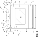
FIG. 2 is a front elevational view of a cooking appliance according to one aspect of the present disclosure; -
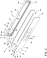
FIG. 3 is an exploded front perspective view of a console assembly for a cooking appliance according to one aspect of the present disclosure; -
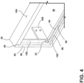
FIG. 4 is a fragmentary perspective view of a console frame of the console assembly taken at the region IV ofFIG. 3 ; -
FIG. 5 is a cross-sectional view of the console frame taken at the line V ofFIG. 3 with an interface module omitted for clarity; -
FIG. 6 is a rear perspective view of a panel of a console assembly of the present disclosure with enlarged views of two locators coupled to the panel; -
FIG. 7 is a rear perspective view of a console assembly according to one aspect of the present disclosure with enlarged views of the locators engaging openings of a console frame; -
FIG. 8 is a front perspective view of an assembly machine performing one step of a method of assembling a console assembly; -
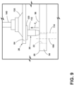
FIG. 9 is an enlarged side view of a locator misaligned with an opening of a console frame during a step of the method of assembling the console assembly; -
FIG. 10 is a block diagram of an assembly machine configured to perform a method of assembling a console assembly according to one aspect of the present disclosure; and -
FIG. 11 is a flow diagram of a method for assembling a console assembly. - The components in the figures are not necessarily to scale, emphasis instead being placed upon illustrating the principles described herein.
- The present illustrated embodiments reside primarily in combinations of method steps and apparatus components related to a console assembly of a cooking appliance. Accordingly, the apparatus components and method steps have been represented, where appropriate, by conventional symbols in the drawings, showing only those specific details that are pertinent to understanding the embodiments of the present disclosure so as not to obscure the disclosure with details that will be readily apparent to those of ordinary skill in the art having the benefit of the description herein. Further, like numerals in the description and drawings represent like elements.
- For purposes of description herein, the terms "upper," "lower," "right," "left," "rear," "front," "vertical," "horizontal," and derivatives thereof shall relate to the disclosure as oriented in
FIG. 2 . Unless stated otherwise, the term "front" shall refertothe surface of the element closer to an intended viewer, and the term "rear" shall refer to the surface of the element further from the intended viewer. However, it is to be understood that the disclosure may assume various alternative orientations, except where expressly specified to the contrary. It is also to be understood that the specific devices and processes illustrated in the attached drawings, and described in the following specification are simply exemplary embodiments of the inventive concepts defined in the appended claims. Hence, specific dimensions and other physical characteristics relating to the embodiments disclosed herein are not to be considered as limiting, unless the claims expressly state otherwise. - The terms "including," "comprises," "comprising," or any other variation thereof, are intended to cover a non-exclusive inclusion, such that a process, method, article, or apparatus that comprises a list of elements does not include only those elements but may include other elements not expressly listed or inherent to such process, method, article, or apparatus. An element preceded by "comprises a ... " does not, without more constraints, preclude the existence of additional identical elements in the process, method, article, or apparatus that comprises the element.
- Referring to
FIGS. 1-7 ,reference numeral 10 generally designates a cooking appliance. Thecooking appliance 10 includes acabinet 12 that defines acooking cavity 14. Adoor 16 is coupled with thecabinet 12 for selectively covering thecooking cavity 14. Aconsole assembly 18 is coupled with thecabinet 12. Theconsole assembly 18 includes aconsole frame 20 coupled with thecabinet 12. Theconsole frame 20 defines at least one opening 22, 24. Theconsole assembly 18 further includes aninterface assembly 26 for controlling an operation of thecooking appliance 10. Abonding member 28 extends between theconsole frame 20 and theinterface assembly 26 to form a permanent bond betweeninterface assembly 26 and theconsole frame 20. At least onelocator interface assembly 26 with theconsole frame 20 during formation of the permanent bond. - Referring more particularly to
FIG. 1 , thecooking appliance 10 is illustrated as a wall-mounted oven. It is contemplated that thecooking appliance 10 described herein may be any one of a variety of cooking appliances including, for example, a microwave oven, a range, a toaster oven, or the like. Similarly, although illustrated as coupled with a wall-mounted oven, it is generally contemplated that theconsole assembly 18 described herein may be used with any one of a variety of cooking appliances. Thecooking appliance 10 includes anappliance frame 34 to which thedoor 16 is coupled. Thedoor 16 is pivotable about ahinge 36 between an open position and a closed position. In the open position, thecooking cavity 14 is accessible from anexterior 38 of thecooking appliance 10. In the closed position, thedoor 16 covers thecooking appliance 10 to allow thecooking cavity 14 to heat in response to initiation of a cooking cycle. - Referring now referring more particularly to
FIG. 2 , thedoor 16 for thecooking appliance 10 includes adoor panel 40 facing theexterior 38 and having a generally rectangular shape. Thedoor panel 40 can be made of glass or another transparent substrate. Thedoor panel 40 includes afrontward surface 42 extending between anupper edge 44 adjacent theinterface assembly 26 and alower edge 46 opposite theupper edge 44. The upper andlower edges lateral edges cooking appliance 10. Ahandle 52 is disposed adjacent theupper edge 44 to allow a user to move thedoor 16 between the open position and the closed position. Askin 54 is disposed on thefrontward surface 42 of thedoor panel 40 adjacent thelower edge 46. Theskin 54 may be comprised of metal and/or have a metalized coating, and may also provide additional insulation between thecooking cavity 14 and theexterior 38. Thedoor 16 may further include aviewing window 56 disposed in acentral portion 58 of thedoor panel 40 to allow a user to view thecooking cavity 14 from theexterior 38. As illustrated, theconsole assembly 18 extends generally parallel with theupper edge 44 along the width W of thecooking appliance 10. Thedoor 16 and theconsole assembly 18 define agap 59 therebetween, the specific dimensions of which are discussed further herein. - The
interface assembly 26 of theconsole assembly 18 extends along the width W of thecooking appliance 10 between a first end 60 (e.g., left end) of theconsole assembly 18 and a second end 62 (e.g., right end) of theconsole assembly 18, opposite thefirst end 60. Theinterface assembly 26 includes aconsole panel 64 and aninterface module 66. Theinterface module 66 connects to arear surface 68 of the panel 64 (seeFIG. 7 ) and may include various user input devices, such asbuttons 70, for operating thecooking appliance 10. Theinterface module 66 also includes adisplay 72, which may be an interactive display capable of receiving touch sensitive inputs from the user to control thecooking appliance 10. In some configurations, thedisplay 72 is operable to indicate the status of thecooking appliance 10, time information, as well as control a heating element of thecooking appliance 10. Thepanel 64 may be made of glass or another insulative material. Thepanel 64 has a generally rectangular shape and includes afront surface 74, opposite therear surface 68, extending between side edges 76, 78 that are spaced apart approximately by the width W of thecooking appliance 10. Atop edge 80 and abottom edge 82 of thefront surface 74 extend between the side edges 76, 78, with thebottom edge 82 delimiting thegap 59 between thedoor 16 and theconsole assembly 18. According to some aspects of the present disclosure, a first distance across thegap 59 is approximately 5 mm. According to some aspects of the present disclosure, the first distance is in the range of 2 mm and 8 mm. The first distance is measured along any line between theupper edge 44 of thedoor 16 and thebottom edge 82 of theconsole assembly 18 in a direction corresponding to a height H of the console assembly 18 (e.g., substantially parallel to the lateral edges 48, 50 and/or the side edges 76, 78). - According to some aspects of the present disclosure, various features described herein as features of the
console assembly 18 may also be referred to as features of an individual component of theconsole assembly 18, and vice versa. For example, the ends 60, 62 of theconsole assembly 18 may also be referred to as ends 60, 62 of thepanel 64 and/or theinterface assembly 26. Similarly, at least some of therear surface 68 of thepanel 64 may be referred to as therear surface 68 of theinterface assembly 26, for example, portions of therear surface 68 not adhered with theinterface module 66. - According to some aspects of the present disclosure, a
left side edge 76 of the side edges 76, 78 is aligned with a leftlateral edge 48 of the lateral edges 48, 50. Similarly, aright side edge 78 of the side edges 76, 78 is aligned with a rightlateral edge 50 of the lateral edges 48, 50. For example, the leftlateral edge 48 may be substantially collinear with theleft side edge 76. Similarly, the rightlateral edge 50 may be substantially collinear with theright side edge 78. According to some configurations, the left and right side edges 76, 78 extend along first and second lines, respectively, and the left and right lateral edges 48, 50 extend along third and fourth lines, respectively. In some configurations, the first line and the second line are parallel to and spaced from one another in a left or right direction (e.g., laterally) by a second distance. Similarly, the second and fourth lines may be parallel to and spaced from one another in the left or right directions by the second distance. The second distance may be in the range of greaterthan 0 mm to 2 mm. In these configurations, the lateral edges 48, 50 and the side edges 76, 78 are substantially aligned with one another. - Referring now to
FIGS. 3-5 , the at least onelocator first locator 30 and asecond locator 32. Although described herein as incorporating twolocators locators console assembly 18. Thefirst locator 30 is disposed adjacent thefirst end 60 of theconsole assembly 18 and thesecond locator 32 is disposed adjacent thesecond end 62 of theconsole assembly 18. The first andsecond locators second pins second locators locators console assembly 18. In general, the first andsecond locators openings 22, 24) may be a female part of the connection arrangement. Alternatively, the male part is formed on theconsole frame 20 and the female part is formed on thepanel 64. - Referring more particularly to the
console frame 20, theconsole frame 20 includes aperipheral member 84 extending about aperiphery 86 of theconsole frame 20. Theperipheral member 84 includes anouter surface 88 that faces therear surface 68 of thepanel 64. As illustrated inFIG. 3 , theconsole frame 20 defines a hollow 90 disposed in acentral part 92 of theconsole frame 20 and extending through a thickness of theconsole frame 20. According to some configurations, the hollow 90 is omitted and theconsole frame 20 may form a plate or other connecting structure extending between the first and second ends 60, 62. In configurations incorporating the hollow 90, theinterface assembly 26 may be accessible when theconsole assembly 18 is detached from the cooking appliance 10 (e.g., via access from a backside of the console assembly 18). - The
console frame 20 further includes asupport member 94 that extends radially inwardly from theperipheral member 84 and includes aninner surface 96 upon which thebonding member 28 is disposed as depicted inFIG. 4 . Thesupport member 94 may be arcuate in shape and form aflange 98 that extends annularly from theperipheral member 84. Theinner surface 96 may extend generally parallel to theouter surface 88 and is alternatively referred to herein as a recessed surface. Theconsole frame 20 defines anouter recess 100 having a depth D between theouter surface 88 and theinner surface 96. In some configurations, the depth D of theouter recess 100 is defined as the distance between theinner surface 96 and a plane in which theouter surface 88 resides, measured in a direction generally orthogonal to the plane. This direction may also correspond to a horizontal direction when theconsole assembly 18 is attached with a wall-mounted oven. The plane may also be adjacent to the new surface of theconsole panel 64 when theconsole assembly 18 is assembled. - In addition to the
console assembly 18 being generally aligned with thedoor 16 of thecooking appliance 10, components of theconsole assembly 18 may further be aligned with one another. For example, thepanel 64 is substantially aligned with theconsole frame 20 along thetop edge 80 and the side edges 76, 78. More specifically, atop surface 102 of thepanel 64 corresponding to thetop edge 80 of thepanel 64 is substantially coplanar with anupper surface 104 of theconsole frame 20. In this way, thepanel 64 may be flush with theconsole frame 20 along a top of theconsole assembly 18. Theconsole panel 64 may further be substantially flush with theconsole frame 20 along the side edges 76, 78. In some configurations, a left side surface of theconsole frame 20 and a left side surface of thepanel 64 are laterally spaced from one another in the right or left directions in the range of 0 mm (e.g., coplanar) and 2 mm. Similarly, a right side surface of theconsole frame 20 may be laterally spaced from a right side surface of thepanel 64 in the right or left directions in the range of 0 mm (e.g., coplanar) and 2 mm. - According to some aspects, the side surface of the
console frame 20 may be spaced laterally outwardly from the corresponding side surface of theconsole panel 64 by approximately 1 mm. In this way, theconsole frame 20 and thepanel 64 may be centrally aligned (e.g., having similar or equal overlap along sides of the console assembly 18) along the width W of thecooking appliance 10. For example, a first midplane dividing thepanel 64 in half along its length may be vertically aligned with a second midplane dividing theconsole frame 20 in half along its length, with theconsole frame 20 extending approximately 1 mm beyond the lateral edges 48, 50 on each side of theconsole assembly 18. According to some aspects, thepanel 64 overhangs theframe 20 along thebottom edge 82 by approximately 0.725 mm (seeFIG. 5 ). - With continued reference to
FIGS. 3-5 , thesupport member 94 may include afirst end bracket 106 and asecond end bracket 108. Thefirst end bracket 106 is disposed adjacent thefirst end 60 and thesecond end bracket 108 is disposed adjacent thesecond end 62. Theinner surface 96 of thesupport member 94 is generally continuous between theend brackets inner surface 96 may be discontinuous along theouter recess 100. For example, theinner surface 96 may be omitted along portions of theconsole frame 20 not necessary for supporting thebonding member 28. It is generally contemplated that theinner surface 96 is generally planar. The at least oneopening first opening 22 and asecond opening 24, each formed on theinner surface 96 of thesupport member 94, with thefirst opening 22 formed on thefirst end bracket 106 and thesecond opening 24 formed on thesecond end bracket 108. As further discussed herein, the size and/or shape of thefirst opening 22 may be similar to or different than the size and/or shape of thesecond opening 24. The shape of theopenings locator first opening 22 may be oval-shaped, oblong, rectangular, triangular, etc., while thefirst locator 30 may be cylindrically shaped, square-shaped, etc. These features are discussed in further detail with respect toFIGS. 6 and7 . - The
console frame 20 also includes one ormore securing mechanisms 109 for engaging thecabinet 12 of thecooking appliance 10. A pair of the one ormore securing mechanisms 109 extend from the first and second ends 60, 62 and may provide an outward lateral force to pinch or otherwise couple theconsole assembly 18 with thecooking appliance 10. Other fastening mechanisms may extend from theconsole assembly 18 for attachment with theappliance frame 34. - According to some aspects of the disclosure, the bonding
member 28 is a room temperature vulcanizing glue (RTV glue) comprising silicone. The bondingmember 28 may include one ormore beads 110 of glue positioned adjacentinner surface 96 in theouter recess 100. By disposing thebonding member 28 interior relative to theouter surface 88 and/or theperiphery 86 of theconsole frame 20, glue may be prevented from seeping out of theconsole assembly 18. The bondingmember 28 spans the depth D of theouter recess 100, as illustrated inFIG. 5 . The bondingmember 28 forms a permanent bond between thepanel 64 and theconsole frame 20 following curing of thebonding member 28. In some configurations, the curing time for the permanent bond is in the range of one hour to several days. According to some aspects, the curing time of the permanent bond is at least 7 days. During the curing time of the permanent bond, theconsole assembly 18 may undergo further operations of an assembly process that involves interaction with external stabilizing features (e.g., clamps, locators, fixtures, etc.). The alignment feature of the present disclosure can maintain stability and/or alignment of thepanel 64 with theconsole frame 20, as well as the permanent bond, during vibration caused by movement of the stabilizing features (e.g., clamps engaging the console assembly 18). - Referring more particularly to
FIG. 5 , the bondingmember 28 is disposed in theouter recess 100 and extends between theinner surface 96 of theconsole frame 20 and therear surface 68 when theconsole assembly 18 is assembled. As illustrated, theconsole panel 64 overhangs theconsole frame 20 along thebottom edge 82 of theconsole panel 64 and is generally flush with theconsole frame 20 along thetop edge 80. The relative position of theconsole panel 64 and theconsole frame 20, such as the overhang of thebottom edge 82, may be maintained via the alignment feature of the present disclosure. The alignment feature (e.g., thelocators openings 22, 24) of the present disclosure may provide for a more efficient manufacturing process of theconsole assembly 18 by allowing theconsole assembly 18 to be moved and/or handled in other processes while thebonding member 28 cures. In addition, the alignment feature may provide for a reliable way of limiting misalignment of theconsole assembly 18 while the permanent bond is formed. - Referring now to
FIGS. 6 and7 , details of the first andsecond locators second locators second pins rear surface 68 of thepanel 64. Eachpin body 112 that extends along acentral axis 114 between aproximal end 116 and adistal end 118. When thepins openings distal end 118 is received in thecorresponding opening body 112. Eachpin body 112 for supporting thebody 112 in an upright configuration, as illustrated. Thebase 120 is generally rectangular in shape, though any shape may be provided to provide stability to thebody 112. Thebase 120 includes anattachment surface 122 that faces theinterface assembly 26 and anintermediate surface 124 that connects the base 120 with thebody 112 at theproximal end 116. Anattachment member 126 is disposed between theinterface assembly 26 and the first andsecond pins pins interface assembly 26. Theattachment member 126 includes afirst surface 128 and asecond surface 130 that is opposite thefirst surface 128. Thefirst surface 128 adhesively couples with therear surface 68 of theinterface assembly 26, and thesecond surface 130 adhesively couples with theattachment surface 122 of eachpin attachment member 126 is a two-sided tape that may extend beyond theattachment surface 122 in an elongated manner along therear surface 68, as illustrated. - The
body 112 may have a conical or frustoconical shape between theproximal end 116 and thedistal end 118, though any shape cable of engaging theopenings interface assembly 26 with theconsole frame 20 can be used. In some configurations, thebody 112 has a frustoconical shape adjacent thedistal end 118 and a cylindrical shape at theproximal end 116. In some configurations, thefirst pin 30 and thesecond pin 32 may be substantially similar or identical in structure, and in other configurations thepins first pin 30 has a first diameter Ø1 and thesecond pin 32 has a second diameter Ø2. In this example, the first diameter Ø1 and the second diameter Ø2 are substantially equal. The first and second diameters Ø1, Ø2 may be taken along a plane perpendicular to thecentral axis 114 at any point along thebody 112 of thepin proximal end 116. Eachpin distal end 118. For example, eachlocator base 120. In this configuration, the layer of sheet metal defines a grooved hole in which thepin body 112 is disposed and fastens to. The clinch pin may have a tapered head such that theattachment surface 122 of the layer of sheet metal is generally flat. In some configurations, thepins console assembly 18 when viewed from theexterior 38. - Referring more particularly to the
panel 64 illustrated inFIG. 6 , one ormore etchings 132 may be formed on therear surface 68 of thepanel 64 corresponding to a location of the various components attached to therear surface 68. For example,etchings 132 may be formed on therear surface 68 of thepanel 64 adjacent a location at which theinterface assembly 26 is attached. More particularly, thebuttons 70 of theinterface assembly 26 may align with one ormore etchings 132 on thepanel 64. Theetchings 132, or holes, in thepanel 64 may allow interaction with theinterface assembly 26 through thepanel 64 from theexterior 38. - Referring more particularly to
FIG. 7 , particular aspects of theopenings console assembly 18 in an assembled configuration. As illustrated, thefirst opening 22 is substantially circular and corresponds to the circular shape of a cross-section of thebody 112 of thefirst pin 30. Thesecond opening 24 is illustrated as having an oblong shape receiving apin 32 having a circular cross-section. In this configuration, thefirst opening 22 is referred to as a narrow opening and thesecond opening 24 is referred to as a wide opening. The locating arrangement (e.g., theopenings locators 30, 32) allows thepanel 64 to be substantially aligned with theconsole frame 20 while allowing flexibility within a given tolerance. For example, a tolerance corresponding to alignment of thepanel 64 with theconsole frame 20 may be ± 1 mm along the right and left sides of theconsole assembly 18, as previously discussed. In the configuration illustrated, thefirst opening 22 has a first perimeter P1 that defines a first area A1 of thefirst opening 22. Thesecond opening 24 has a second perimeter P2 that defines a second area A2 of thesecond opening 24. As illustrated, the second area A2 is greater than the first area A1. The greater area A2 of thesecond opening 24 can allow for sufficient room or spacing during the assembly process of thepanel 64 with theconsole frame 20 to prevent unnecessary breakage or damage to one or more of the components of theconsole assembly 18. While illustrated as an oblong, thesecond opening 24 may form any one of a variety of shapes having a lateral dimension different than a longitudinal dimension, such as a rectangle, an oval, or the like. It is further contemplated that each opening may be referred to as thru-holes support member 94. In this way, the thru-holes locators locators console frame 20. - Although illustrated as an oblong having a long axis in the right to left direction of the
console assembly 18, it is generally contemplated that thewide opening 24 may extend in an up/down direction to allow deviation in the up-and-down directions. In some configurations, thefirst opening 22 is oblong in the right-to-left direction, and thesecond opening 24 is oblong in the up/down direction or vice versa. It is also generally contemplated that while the illustrated configuration includes thenarrow opening 22 and anoblong opening 24, either or both of theopenings first opening 22 has a first width w1, and thesecond opening 24 has a second width w2. The second width w2 is greater than the first width w1. The first width w1 may correspond to (e.g., be slightly larger than) the first diameter Ø1, and the second width w2 may correspond to (e.g., be slightly larger than) the second diameter Ø2 and a width of the oblong along a longitudinal axis of the oblong. The longitudinal axis is the longer of two axes of the oblong. In some configurations, thefirst opening 22 has a diameter in the range of 8% and 12% greater than either or both of the widths or the diameters Ø1, Ø2 of thelocators - Referring now to
FIG. 8 , a process for assembling theconsole assembly 18 may be implemented via an assemblingmachine 134, such as a robot. Themachine 134 includes anend effector 136 for interacting with theconsole panel 64 of theconsole assembly 18. Themachine 134 can include various selectively controlled mechanisms to allow for a controlled release of thepanel 64. As illustrated, theend effector 136 includes a plurality ofsuction cups 138 attached to thefront surface 74 of thepanel 64. Eachsuction cup 138 is disposed at one end of asleeve 140 that houses a fitting 142. The fitting 142 may be in fluid communication with thesuction cup 138 and with a vacuum generator 144 (FIG. 10 ) for supplying suction to thesuction cups 138 viafluid connections 146. In general, themachine 134 may be driven by one or moreactuator modules 148, such as a servo motor configured to drive one axis of therobot 134. Theconsole frame 20 is illustrated as disposed in afixture 150 that stabilizes theconsole frame 20 while theassembly machine 134 applies thepanel 64 to theconsole frame 20. Themachine 134 moves thepanel 64 toward theconsole frame 20 after application of thebonding member 28 to theconsole frame 20 and after application of the at least onelocator panel 64. - Referring now to
FIG. 9 , theconsole panel 64 is illustrated as being misaligned with theconsole frame 20 during assembly of theconsole assembly 18. As will be further discussed herein, the process for assembling theconsole assembly 18 may include a control unit 152 (seeFIG. 10 ) configured to associate data from one ormore sensors panel 64 when thelocator console frame 20. As illustrated inFIG. 9 , thelocator support member 94 of theframe 20 due to misalignment of thefirst locator 30 with thefirst opening 22. As theassembly machine 134 advances thepanel 64 downwardly toward theframe 20, the resistance force FR may be detected or inferred by thecontrol unit 152 from the one ormore sensors control unit 152. Thecontrol unit 152 may determine that thepanel 64 and theconsole frame 20 are misaligned based on the resistance force FR. Thecontrol unit 152 may re-position theend effector 136 to re-attempt coupling the console panel 64 (of the interface assembly 26) with theconsole frame 20. For example, theend effector 136 may be retracted from adjacent thefixture 150, adjusted to move theconsole panel 64, and re-advanced toward theconsole frame 20. It is generally contemplated that although described in detail with respect to thefirst locator 30 and thefirst opening 22, the misalignment condition may also or alternatively be detected with thesecond locator 32 and thesecond opening 24. Thecontrol unit 152 may be configured to readjust theend effector 136 based on either or both of thelocators console assembly 18. - According to some aspects, the resistance force FR is measured, via the one or
more sensors control unit 152 is configured to associate the resistance force FR with a debonded condition corresponding to the locators(s) 30, 32 becoming debonded from theconsole panel 64. In one example, the debonded condition corresponds to a resistance force FR of 100 Newtons or more. Thecontrol unit 152 is also configured to associate the resistance force FR with a passing condition corresponding to an acceptable alignment tolerance. For example, the passing condition can correspond to a resistance force FR of 100 Newtons or less. In some examples, the acceptable alignment tolerance corresponds to an alignment tolerance of 0.5 mm from thecentral axis 114 of thelocator FIG. 9 ) and corresponds to a resistance force FR of approximately 120 Newtons. - Referring now to
FIG. 10 , thecontrol unit 152 of themachine 134 may include aprocessor 160 and amemory 162. Thememory 162 may store instructions that, when executed by theprocessor 160, cause themachine 134 to move. The one ormore sensors pressure sensor 154 and/or aproximity sensor 156 in communication with theprocessor 160. Thecontrol unit 152 may determine, based on the data provided from thepressure sensor 154 and/or theproximity sensor 156, that the resistance force FR is present. It is generally contemplated that the resistance force FR may be directly measured via a force or torque measuring device. Such a device may be incorporated into the one or moreactuator modules 148 of themachine 134. One or more theactuator modules 148 may include anactuator 166, such as a motor or a servo motor, and acorresponding sensing circuit 168 for measuring torque, force, acceleration, distance, or the like. For example, themachine 134 may be movable viaservo modules 166 havingservo motors 166 and correspondingtorque detection sensors 168. Based on the torque detection, thecontrol unit 152 may determine that a resistance force FR is present and may control one or more of theactuators 166 to adjust the position of theassembly machine 134. - In some examples, torque data provided by the one or more
actuator modules 148 is used to identify or infer the resistance force FR. In still other examples, theair pressure sensor 154 can be associated with thesuction cups 138 and used to detect or infer the resistance force FR based on a detected change in air pressure. Based on a misalignment condition, thecontrol unit 152 may control theassembly machine 134 to position theassembly machine 134 along a different axis of alignment. In addition, thecontrol unit 152 may control the vacuum generator to increase or decrease a suction force associated with thesuction cups 138 in response to the resistance force FR. It is generally contemplated that any one of a variety ofsensors pressure sensor 154, a vacuum sensor, an encoder, data collected from a servo motor, or the like (e.g., ductwork data, torque data). - Referring now to
FIG. 11 , amethod 1100 for assembling theconsole assembly 18 of thecooking appliance 10 includes coupling one ormore locators interface assembly 26 of theconsole assembly 18 atstep 1102. Themethod 1100 further includes forming one ormore openings locators console frame 20 of theconsole assembly 18 atstep 1104. Themethod 1100 further includes positioning the one ormore locators more openings step 1106. Themethod 1100 further includes engaging theinterface assembly 26 with theconsole frame 20 atstep 1108. Themethod 1100 further includes receiving force FR data corresponding to the force applied by theinterface assembly 26 to theconsole frame 20 atstep 1110. Themethod 1100 further includes adjusting a position of theinterface assembly 26 based on the force data to align the one ormore locators more openings step 1112. - According to some aspects of the present disclosure, an alignment feature is disposed between the
console frame 20 of theinterface module 66. The alignment feature includes a female mating member and a male mating member. The female mating member may be formed on theconsole assembly 18 and the male mating member may be formed on theinterface module 66. It is generally contemplated that the male mating member may be formed on theconsole assembly 18 and the female mating member may be formed on theinterface module 66. The male member may engage the female member to align theinterface module 66 to theconsole frame 20. In this way, misalignment of the components of theconsole assembly 18 may be reduced. For example, while thebonding member 28 cures, thepanel 64 may be limited in lateral and/or up-and-down movements. This may allow theconsole assembly 18 to undergo other assembly processes (e.g., coupling theconsole assembly 18 with the cooking appliance 10) without causing misalignment of the panel 64 (e.g., glass) with theconsole frame 20. For example, the glass of thepanel 64 and theconsole frame 20 may maintain edge-to-edge alignment during assembly of theconsole assembly 18. - According to one aspect of the present disclosure, a cooking appliance includes a cabinet that defines a cooking cavity. A door is coupled with the cabinet. A console assembly includes a console frame coupled with the cabinet. The console frame defines at least one opening. The console assembly includes an interface assembly for controlling an operation of the cooking appliance. A bonding member extends between the console frame and the interface assembly to form a permanent bond between the interface assembly and the console frame. At least one locator engages the at least one opening to align the interface assembly with the console frame during formation of the permanent bond.
- According to another aspect of the present disclosure, the console assembly extends along a width of the cooking appliance between a first end and a second end, opposite the first end. The at least one locator includes a first pin and the at least one opening includes a first opening. The first opening is disposed adjacent the first end.
- According to still another aspect of the present disclosure, the at least one locator includes a second pin and the at least one opening includes a second opening. The second opening is disposed adjacent the second end. The first pin engages the first opening and the second pin engages the second opening.
- According to yet another aspect of the present disclosure, the first opening has a first width and the second opening has a second width, the second width is greater than the first width.
- According to still another aspect of the present disclosure, the at least one locator is disposed adjacent a rear surface of the interface module.
- According to yet another aspect of the present disclosure, the console frame includes a peripheral member that extends about a periphery of the console frame and includes an outer surface. A support member extends from the peripheral member and includes an inner surface. The console frame defines an outer recess that has a depth between the outer surface and the inner surface. The at least one opening is formed on the inner surface.
- According to another aspect of the present disclosure, the bonding member is disposed in the recess.
- According to still another aspect of the present disclosure, the bonding member spans the depth of the recess.
- According to another aspect of the present disclosure, at least some of the at least one locator spans the depth.
- According to still another aspect of the present disclosure, the at least one locator includes a body that extends between a proximal end and a distal end and into the at least one opening along a central axis. A base is coupled to the body. The base includes an attachment surface that faces the interface module and an intermediate surface connects the base with the body at the proximal end.
- According to another aspect of the present disclosure, the body has a frustoconial shape adjacent to the distal end.
- According to another aspect of the present disclosure, an attachment member is disposed between the interface module and the at least one locator to couple the at least one locator with the interface module.
- According to another aspect of the present disclosure, the attachment member includes a first surface and a second surface that is opposite the first surface. The first surface adhesively couples with a rear surface of the interface module and the second surface adhesively couples with the at least one locator.
- According to another aspect, a console assembly for a cooking appliance includes an interface assembly for controlling an operation of the cooking appliance. A console frame operably couples the interface assembly with the cooking appliance. The console frame defines at least one opening. A bonding member is disposed between the console frame and the interface assembly. At least one pin extends from the interface assembly and is configured to engage the at least one opening to align the interface assembly with the console frame.
- According to another aspect of the present disclosure, the at least one pin includes a first pin that has a first width. A second pin that is spaced from the first pin and that has a second width. The first diameter and the second diameter are substantially equal.
- According to another aspect of the present disclosure, the at least one opening includes a first opening and a second opening. The first pin engages the first opening and the second pin engages the second opening.
- According to still another aspect of the present disclosure, the first opening has a first perimeter that defines a first area of the first opening and the second opening has a second perimeter that defines a second area of the second opening. The second area is greater than the first area.
- According to yet another aspect of the present disclosure, the first opening is circular and the second opening is obround.
- According to another aspect of the present disclosure, each of the first opening and the second opening has a diameter in the range of 8% and 12% greater than each of the first diameter and the second diameter.
- According to yet another aspect, a method used to assemble a console assembly of a cooking appliance includes a step where a locator is coupled with an interface assembly of the console assembly. An opening is operable to receive the locator in a console frame of the console assembly. The locator is adjacent to the opening. The interface assembly engages with the console frame. Force data is received and corresponds to a force applied by the interface assembly to the console frame. A position of the interface assembly is adjusted based on the force data to align the locator with the opening.
- According to another aspect of the present disclosure, the first width is in the range of 8% and 12% greater than each of the first diameter and the second diameter.
- It will be understood by one having ordinary skill in the art that construction of the described disclosure and other components is not limited to any specific material. Other exemplary embodiments of the disclosure disclosed herein may be formed from a wide variety of materials, unless described otherwise herein.
- For purposes of this disclosure, the term "coupled" (in all of its forms, couple, coupling, coupled, etc.) generally means the joining of two components (electrical or mechanical) directly or indirectly to one another. Such joining may be stationary in nature or movable in nature. Such joining may be achieved with the two components (electrical or mechanical) and any additional intermediate members being integrally formed as a single unitary body with one another or with the two components. Such joining may be permanent in nature or may be removable or releasable in nature unless otherwise stated.
- It is also important to note that the construction and arrangement of the elements of the disclosure as shown in the exemplary embodiments is illustrative only. Although only a few embodiments of the present innovations have been described in detail in this disclosure, those skilled in the art who review this disclosure will readily appreciate that many modifications are possible (e.g., variations in sizes, dimensions, structures, shapes and proportions of the various elements, values of parameters, mounting arrangements, use of materials, colors, orientations, etc.) without materially departing from the novel teachings and advantages of the subject matter recited. For example, elements shown as integrally formed may be constructed of multiple parts or elements shown as multiple parts may be integrally formed, the operation of the interfaces may be reversed or otherwise varied, the length or width of the structures and/or members or connector or other elements of the system may be varied, the nature or number of adjustment positions provided between the elements may be varied. It should be noted that the elements and/or assemblies of the system may be constructed from any of a wide variety of materials that provide sufficient strength or durability, in any of a wide variety of colors, textures, and combinations. Accordingly, all such modifications are intended to be included within the scope of the present innovations. Other substitutions, modifications, changes, and omissions may be made in the design, operating conditions, and arrangement of the desired and other exemplary embodiments without departing from the spirit of the present innovations.
- It will be understood that any described processes or steps within described processes may be combined with other disclosed processes or steps to form structures within the scope of the present disclosure. The exemplary structures and processes disclosed herein are for illustrative purposes and are not to be construed as limiting.
Claims (15)
- A cooking appliance (10) comprising:a cabinet (12) defining a cooking cavity (14);a door (16) coupled with the cabinet (12) for selectively covering the cooking cavity (14); anda console assembly (18) coupled with the cabinet (12), the console assembly (18) comprising:a console frame (20) coupled with the cabinet (12), the console frame (20) defining at least one opening (22, 24);an interface assembly (26) for controlling an operation of the cooking appliance (10);a bonding member (28) extending between the console frame (20) and the interface assembly (26) to form a permanent bond between the interface assembly (26) and the console frame (20); andat least one locator (30, 32) engaging the at least one opening (22, 24) to align the interface assembly (26) with the console frame (20) during formation of the permanent bond.
- The cooking appliance (10) of claim 1, wherein the console assembly (18) extends along a width (W) of the cooking appliance (10) between a first end (60) and a second end (62), opposite the first end (60), wherein the at least one locator (30, 32) includes a first pin (30) and the at least one opening (22, 24) includes a first opening (22), and wherein the first opening (22) is disposed adjacent the first end (60).
- The cooking appliance (10) of claim 2, wherein the at least one locator (30, 32) includes a second pin (32) and the at least one opening (22, 24) includes a second opening (24), wherein the second opening (24) is disposed adjacent the second end (62), and wherein the first pin (30) engages the first opening (22) and the second pin (32) engages the second opening (24).
- The cooking appliance (10) of claim 3, wherein the first opening (22) has a first width (w1) and the second opening (24) has a second width (w2), the second width (w2) being greater than the first width (w1).
- The cooking appliance (10) of either of claim 3 or claim 4, wherein the first opening (22) is circular and the second opening (24) is obround.
- The cooking appliance (10) of claim 4, wherein the first and second pins (30, 32) have first and second diameters (Ø1, Ø2) wherein the first width (w1) is in the range of 8 percent and 12 percent greater than the first and second diameters (Ø1, Ø2).
- The cooking appliance (10) of any one of claims 1-6, the console frame (20) comprising:a peripheral member (84) extending about a periphery (86) of the console frame (20) and including an outer surface (88); anda support member extending from the peripheral member (84) and including an inner surface (96), the console frame (20) defining an outer recess (100) having a depth (D) between the outer surface (88) and the inner surface (96), wherein the at least one opening (22, 24) is formed on the inner surface (96).
- The cooking appliance (10) of claim 7, wherein the bonding member (28) is disposed in the outer recess (100).
- The cooking appliance (10) of either of claim 7 or claim 8, wherein the bonding member (28) spans the depth (D) of the outer recess (100).
- The cooking appliance (10) of any one of claims 7-9, wherein at least some of the at least one locator (30, 32) spans the depth (D).
- The cooking appliance (10) of any one of claims 1-10, the at least one locator (30, 32) comprising:a body (112) extending between a proximal end (116) and a distal end (118) and into the at least one opening (22, 24) along a central axis (114); anda base (120) coupled to the body (112), the base (120) including an attachment surface facing the interface assembly (26) and an intermediate surface connecting the base (120) with the body (112) at the proximal end (116).
- The cooking appliance (10) of claim 7, wherein the body (112) has a frustoconical shape adjacent the distal end (118).
- The cooking appliance (10) of any one of claims 1-12, further comprising:
an attachment member (126) disposed between the interface assembly (26) and at least one locator (30, 32) to couple the at least one locator (30, 32) with the interface assembly (26). - The cooking appliance (10) of claim 13, wherein the attachment member (126) includes a first surface (128) and a second surface (130) opposite the first surface (128), the first surface (128) adhesively coupling with a rear surface (68) of the interface assembly (26) and the second surface (130) adhesively coupling with the at least one locator (30, 32).
- The cooking appliance (10) of any one of claims 1-13, wherein the at least one locator (30, 32) is disposed adjacent a rear surface (68) of the interface assembly (26).
Applications Claiming Priority (1)
| Application Number | Priority Date | Filing Date | Title |
|---|---|---|---|
| US17/695,465 US12429228B2 (en) | 2022-03-15 | 2022-03-15 | Console assembly and method for assembling a console assembly of a cooking appliance |
Publications (1)
| Publication Number | Publication Date |
|---|---|
| EP4246044A1 true EP4246044A1 (en) | 2023-09-20 |
Family
ID=85703497
Family Applications (1)
| Application Number | Title | Priority Date | Filing Date |
|---|---|---|---|
| EP23162130.1A Withdrawn EP4246044A1 (en) | 2022-03-15 | 2023-03-15 | Console assembly for a cooking appliance |
Country Status (2)
| Country | Link |
|---|---|
| US (1) | US12429228B2 (en) |
| EP (1) | EP4246044A1 (en) |
Families Citing this family (1)
| Publication number | Priority date | Publication date | Assignee | Title |
|---|---|---|---|---|
| US12000597B2 (en) * | 2022-02-04 | 2024-06-04 | Haier Us Appliance Solutions, Inc. | Systems and methods for the adjustment of toe kick plates |
Citations (8)
| Publication number | Priority date | Publication date | Assignee | Title |
|---|---|---|---|---|
| EP2650613A1 (en) * | 2012-04-13 | 2013-10-16 | Electrolux Home Products Corporation N.V. | Appliance, especially domestic appliance, and method of mounting such an appliance |
| DE102014224116A1 (en) * | 2014-11-26 | 2015-12-03 | E.G.O. Elektro-Gerätebau GmbH | hob |
| US20160201877A1 (en) * | 2013-10-29 | 2016-07-14 | Whirlpool Corporation | Console assembly with integrated light reflector cups |
| US20190121223A1 (en) * | 2016-04-15 | 2019-04-25 | Sony Corporation | Compound-eye camera module and electronic device |
| DE102019203114A1 (en) * | 2019-03-07 | 2020-09-10 | BSH Hausgeräte GmbH | Household refrigeration device with a display and / or control unit |
| US20210010676A1 (en) * | 2019-07-09 | 2021-01-14 | Bsh Home Appliances Corporation | Cooking appliance having a removable control panel |
| CN109915862B (en) * | 2019-03-14 | 2021-06-18 | 广东美的厨房电器制造有限公司 | Interaction assembly and household appliance |
| CN113545175A (en) * | 2019-03-13 | 2021-10-22 | 伊莱克斯家用电器股份公司 | Control panel for an appliance, in particular for a household appliance, and method for assembling said control panel |
Family Cites Families (10)
| Publication number | Priority date | Publication date | Assignee | Title |
|---|---|---|---|---|
| US4074825A (en) | 1976-11-16 | 1978-02-21 | Gsw Limited/Limitee | End cap assembly for an appliance control panel |
| US4894493A (en) | 1988-11-04 | 1990-01-16 | General Electric Company | Membrane touch control panel assembly for an appliance with a glass control panel |
| US9513013B2 (en) | 2011-07-28 | 2016-12-06 | Bsh Home Appliances Corporation | Manifold assembly for a domestic kitchen appliance |
| US9476594B2 (en) * | 2012-12-05 | 2016-10-25 | BSH Home Appliances Corporatíon | Domestic cooking appliance having a gas switch mounting system |
| EP2851620B2 (en) | 2013-09-19 | 2026-01-21 | Electrolux Appliances Aktiebolag | Touch screen control panel and kitchen appliance comprising such a control panel |
| KR101662941B1 (en) * | 2015-02-05 | 2016-10-05 | 엘지전자 주식회사 | Cooking apparatus and touch sensor assembly for cooking apparatus |
| US9732963B2 (en) | 2015-06-17 | 2017-08-15 | Haier Us Appliance Solutions, Inc. | Appliance control panel assembly |
| US10801732B2 (en) * | 2019-02-25 | 2020-10-13 | Haier Us Appliance Solutions, Inc. | Control console assembly for a cooking appliance |
| US11019746B1 (en) * | 2020-03-09 | 2021-05-25 | Whirlpool Corporation | Lateral alignment system for an appliance control panel assembly and method |
| US12535221B2 (en) * | 2021-10-28 | 2026-01-27 | Haier Us Appliance Solutions, Inc. | Cooktop appliance with unifying alignment bracket |
-
2022
- 2022-03-15 US US17/695,465 patent/US12429228B2/en active Active
-
2023
- 2023-03-15 EP EP23162130.1A patent/EP4246044A1/en not_active Withdrawn
Patent Citations (8)
| Publication number | Priority date | Publication date | Assignee | Title |
|---|---|---|---|---|
| EP2650613A1 (en) * | 2012-04-13 | 2013-10-16 | Electrolux Home Products Corporation N.V. | Appliance, especially domestic appliance, and method of mounting such an appliance |
| US20160201877A1 (en) * | 2013-10-29 | 2016-07-14 | Whirlpool Corporation | Console assembly with integrated light reflector cups |
| DE102014224116A1 (en) * | 2014-11-26 | 2015-12-03 | E.G.O. Elektro-Gerätebau GmbH | hob |
| US20190121223A1 (en) * | 2016-04-15 | 2019-04-25 | Sony Corporation | Compound-eye camera module and electronic device |
| DE102019203114A1 (en) * | 2019-03-07 | 2020-09-10 | BSH Hausgeräte GmbH | Household refrigeration device with a display and / or control unit |
| CN113545175A (en) * | 2019-03-13 | 2021-10-22 | 伊莱克斯家用电器股份公司 | Control panel for an appliance, in particular for a household appliance, and method for assembling said control panel |
| CN109915862B (en) * | 2019-03-14 | 2021-06-18 | 广东美的厨房电器制造有限公司 | Interaction assembly and household appliance |
| US20210010676A1 (en) * | 2019-07-09 | 2021-01-14 | Bsh Home Appliances Corporation | Cooking appliance having a removable control panel |
Also Published As
| Publication number | Publication date |
|---|---|
| US12429228B2 (en) | 2025-09-30 |
| US20230296261A1 (en) | 2023-09-21 |
Similar Documents
| Publication | Publication Date | Title |
|---|---|---|
| JP7005774B2 (en) | Bonding device and bonding method for irregular curved cover plate and flexible screen | |
| US12429228B2 (en) | Console assembly and method for assembling a console assembly of a cooking appliance | |
| CN103546857A (en) | Electrodynamic loudspeaker, method of assembling same, method of forming electrical conductor or electrical contact | |
| US20180141500A1 (en) | Vehicle glazing comprising a mounting plate for fixing several accessories, mounting plate and fixing method | |
| US10779419B2 (en) | Wall apparatus for controlling utilities | |
| CN103148463B (en) | Frame body with removable positioning device, backlight module, display module and manufacturing method thereof | |
| EP3879180A1 (en) | Appliance comprising control panel assembly | |
| EP4191174A1 (en) | Insulated structure for an appliance | |
| WO2003092985A1 (en) | Roller driving apparatus of laminator | |
| JP6743187B2 (en) | Weight applicator head for improved wetout | |
| CN212869231U (en) | An adjustment structure for a display screen of a door body of a household appliance, and a display screen bracket | |
| CN114659259B (en) | Air conditioner housing and air conditioner | |
| CN113059288B (en) | Tapping jig, tapping equipment and tapping method for display panel | |
| CN223215548U (en) | Patch device of electric appliance | |
| CN110873506B (en) | A hinge structure for positioning door body and refrigerator | |
| CN223795581U (en) | Surface-attached decorative plate for refrigerator air duct panel | |
| CN203228573U (en) | Section bar decorating part, panel assembly provided with same and indoor unit of air conditioner | |
| CN115831002A (en) | Display device | |
| CN113188248B (en) | Pasting and positioning device for curved panels | |
| WO2014102359A1 (en) | A linking mechanism | |
| CN223090729U (en) | Fume exhaust fan and switch assembly thereof | |
| CN217336271U (en) | dismantling device | |
| CN222424419U (en) | Controller | |
| CN109774170B (en) | A pasting device | |
| CN220374244U (en) | Edge covering assembly, vehicle window and vehicle |
Legal Events
| Date | Code | Title | Description |
|---|---|---|---|
| PUAI | Public reference made under article 153(3) epc to a published international application that has entered the european phase |
Free format text: ORIGINAL CODE: 0009012 |
|
| STAA | Information on the status of an ep patent application or granted ep patent |
Free format text: STATUS: THE APPLICATION HAS BEEN PUBLISHED |
|
| AK | Designated contracting states |
Kind code of ref document: A1 Designated state(s): AL AT BE BG CH CY CZ DE DK EE ES FI FR GB GR HR HU IE IS IT LI LT LU LV MC ME MK MT NL NO PL PT RO RS SE SI SK SM TR |
|
| STAA | Information on the status of an ep patent application or granted ep patent |
Free format text: STATUS: REQUEST FOR EXAMINATION WAS MADE |
|
| 17P | Request for examination filed |
Effective date: 20240318 |
|
| RBV | Designated contracting states (corrected) |
Designated state(s): AL AT BE BG CH CY CZ DE DK EE ES FI FR GB GR HR HU IE IS IT LI LT LU LV MC ME MK MT NL NO PL PT RO RS SE SI SK SM TR |
|
| GRAP | Despatch of communication of intention to grant a patent |
Free format text: ORIGINAL CODE: EPIDOSNIGR1 |
|
| STAA | Information on the status of an ep patent application or granted ep patent |
Free format text: STATUS: GRANT OF PATENT IS INTENDED |
|
| INTG | Intention to grant announced |
Effective date: 20241202 |
|
| STAA | Information on the status of an ep patent application or granted ep patent |
Free format text: STATUS: THE APPLICATION IS DEEMED TO BE WITHDRAWN |
|
| 18D | Application deemed to be withdrawn |
Effective date: 20250403 |