EP4246040A1 - Circulating fluidized bed boiler and a method for operating a circulating fluidized bed boiler - Google Patents
Circulating fluidized bed boiler and a method for operating a circulating fluidized bed boiler Download PDFInfo
- Publication number
- EP4246040A1 EP4246040A1 EP23159568.7A EP23159568A EP4246040A1 EP 4246040 A1 EP4246040 A1 EP 4246040A1 EP 23159568 A EP23159568 A EP 23159568A EP 4246040 A1 EP4246040 A1 EP 4246040A1
- Authority
- EP
- European Patent Office
- Prior art keywords
- heat exchanger
- bed material
- sulphur
- fraction
- material fraction
- Prior art date
- Legal status (The legal status is an assumption and is not a legal conclusion. Google has not performed a legal analysis and makes no representation as to the accuracy of the status listed.)
- Granted
Links
Images





Classifications
-
- F—MECHANICAL ENGINEERING; LIGHTING; HEATING; WEAPONS; BLASTING
- F23—COMBUSTION APPARATUS; COMBUSTION PROCESSES
- F23C—METHODS OR APPARATUS FOR COMBUSTION USING FLUID FUEL OR SOLID FUEL SUSPENDED IN A CARRIER GAS OR AIR
- F23C10/00—Fluidised bed combustion apparatus
- F23C10/18—Details; Accessories
-
- B—PERFORMING OPERATIONS; TRANSPORTING
- B01—PHYSICAL OR CHEMICAL PROCESSES OR APPARATUS IN GENERAL
- B01D—SEPARATION
- B01D53/00—Separation of gases or vapours; Recovering vapours of volatile solvents from gases; Chemical or biological purification of waste gases, e.g. engine exhaust gases, smoke, fumes, flue gases, aerosols
- B01D53/34—Chemical or biological purification of waste gases
- B01D53/46—Removing components of defined structure
- B01D53/68—Halogens or halogen compounds
- B01D53/685—Halogens or halogen compounds by treating the gases with solids
-
- F—MECHANICAL ENGINEERING; LIGHTING; HEATING; WEAPONS; BLASTING
- F22—STEAM GENERATION
- F22B—METHODS OF STEAM GENERATION; STEAM BOILERS
- F22B31/00—Modifications of boiler construction, or of tube systems, dependent on installation of combustion apparatus; Arrangements or dispositions of combustion apparatus
- F22B31/0007—Modifications of boiler construction, or of tube systems, dependent on installation of combustion apparatus; Arrangements or dispositions of combustion apparatus with combustion in a fluidized bed
-
- F—MECHANICAL ENGINEERING; LIGHTING; HEATING; WEAPONS; BLASTING
- F23—COMBUSTION APPARATUS; COMBUSTION PROCESSES
- F23C—METHODS OR APPARATUS FOR COMBUSTION USING FLUID FUEL OR SOLID FUEL SUSPENDED IN A CARRIER GAS OR AIR
- F23C10/00—Fluidised bed combustion apparatus
- F23C10/02—Fluidised bed combustion apparatus with means specially adapted for achieving or promoting a circulating movement of particles within the bed or for a recirculation of particles entrained from the bed
- F23C10/04—Fluidised bed combustion apparatus with means specially adapted for achieving or promoting a circulating movement of particles within the bed or for a recirculation of particles entrained from the bed the particles being circulated to a section, e.g. a heat-exchange section or a return duct, at least partially shielded from the combustion zone, before being reintroduced into the combustion zone
- F23C10/08—Fluidised bed combustion apparatus with means specially adapted for achieving or promoting a circulating movement of particles within the bed or for a recirculation of particles entrained from the bed the particles being circulated to a section, e.g. a heat-exchange section or a return duct, at least partially shielded from the combustion zone, before being reintroduced into the combustion zone characterised by the arrangement of separation apparatus, e.g. cyclones, for separating particles from the flue gases
- F23C10/10—Fluidised bed combustion apparatus with means specially adapted for achieving or promoting a circulating movement of particles within the bed or for a recirculation of particles entrained from the bed the particles being circulated to a section, e.g. a heat-exchange section or a return duct, at least partially shielded from the combustion zone, before being reintroduced into the combustion zone characterised by the arrangement of separation apparatus, e.g. cyclones, for separating particles from the flue gases the separation apparatus being located outside the combustion chamber
-
- F—MECHANICAL ENGINEERING; LIGHTING; HEATING; WEAPONS; BLASTING
- F23—COMBUSTION APPARATUS; COMBUSTION PROCESSES
- F23C—METHODS OR APPARATUS FOR COMBUSTION USING FLUID FUEL OR SOLID FUEL SUSPENDED IN A CARRIER GAS OR AIR
- F23C10/00—Fluidised bed combustion apparatus
- F23C10/18—Details; Accessories
- F23C10/24—Devices for removal of material from the bed
- F23C10/26—Devices for removal of material from the bed combined with devices for partial reintroduction of material into the bed, e.g. after separation of agglomerated parts
-
- F—MECHANICAL ENGINEERING; LIGHTING; HEATING; WEAPONS; BLASTING
- F23—COMBUSTION APPARATUS; COMBUSTION PROCESSES
- F23C—METHODS OR APPARATUS FOR COMBUSTION USING FLUID FUEL OR SOLID FUEL SUSPENDED IN A CARRIER GAS OR AIR
- F23C10/00—Fluidised bed combustion apparatus
- F23C10/18—Details; Accessories
- F23C10/28—Control devices specially adapted for fluidised bed, combustion apparatus
- F23C10/30—Control devices specially adapted for fluidised bed, combustion apparatus for controlling the level of the bed or the amount of material in the bed
-
- F—MECHANICAL ENGINEERING; LIGHTING; HEATING; WEAPONS; BLASTING
- F23—COMBUSTION APPARATUS; COMBUSTION PROCESSES
- F23G—CREMATION FURNACES; CONSUMING WASTE PRODUCTS BY COMBUSTION
- F23G5/00—Incineration of waste; Incinerator constructions; Details, accessories or control therefor
- F23G5/30—Incineration of waste; Incinerator constructions; Details, accessories or control therefor having a fluidised bed
-
- F—MECHANICAL ENGINEERING; LIGHTING; HEATING; WEAPONS; BLASTING
- F23—COMBUSTION APPARATUS; COMBUSTION PROCESSES
- F23G—CREMATION FURNACES; CONSUMING WASTE PRODUCTS BY COMBUSTION
- F23G5/00—Incineration of waste; Incinerator constructions; Details, accessories or control therefor
- F23G5/44—Details; Accessories
- F23G5/48—Preventing corrosion
-
- F—MECHANICAL ENGINEERING; LIGHTING; HEATING; WEAPONS; BLASTING
- F23—COMBUSTION APPARATUS; COMBUSTION PROCESSES
- F23J—REMOVAL OR TREATMENT OF COMBUSTION PRODUCTS OR COMBUSTION RESIDUES; FLUES
- F23J15/00—Arrangements of devices for treating smoke or fumes
- F23J15/02—Arrangements of devices for treating smoke or fumes of purifiers, e.g. for removing noxious material
-
- F—MECHANICAL ENGINEERING; LIGHTING; HEATING; WEAPONS; BLASTING
- F23—COMBUSTION APPARATUS; COMBUSTION PROCESSES
- F23J—REMOVAL OR TREATMENT OF COMBUSTION PRODUCTS OR COMBUSTION RESIDUES; FLUES
- F23J7/00—Arrangement of devices for supplying chemicals to fire
-
- B—PERFORMING OPERATIONS; TRANSPORTING
- B01—PHYSICAL OR CHEMICAL PROCESSES OR APPARATUS IN GENERAL
- B01D—SEPARATION
- B01D2251/00—Reactants
-
- B—PERFORMING OPERATIONS; TRANSPORTING
- B01—PHYSICAL OR CHEMICAL PROCESSES OR APPARATUS IN GENERAL
- B01D—SEPARATION
- B01D2251/00—Reactants
- B01D2251/20—Reductants
- B01D2251/21—Organic compounds not provided for in groups B01D2251/206 or B01D2251/208
-
- B—PERFORMING OPERATIONS; TRANSPORTING
- B01—PHYSICAL OR CHEMICAL PROCESSES OR APPARATUS IN GENERAL
- B01D—SEPARATION
- B01D2251/00—Reactants
- B01D2251/60—Inorganic bases or salts
- B01D2251/608—Sulfates
-
- B—PERFORMING OPERATIONS; TRANSPORTING
- B01—PHYSICAL OR CHEMICAL PROCESSES OR APPARATUS IN GENERAL
- B01D—SEPARATION
- B01D2257/00—Components to be removed
- B01D2257/20—Halogens or halogen compounds
- B01D2257/204—Inorganic halogen compounds
- B01D2257/2045—Hydrochloric acid
-
- B—PERFORMING OPERATIONS; TRANSPORTING
- B01—PHYSICAL OR CHEMICAL PROCESSES OR APPARATUS IN GENERAL
- B01D—SEPARATION
- B01D2257/00—Components to be removed
- B01D2257/30—Sulfur compounds
- B01D2257/302—Sulfur oxides
-
- B—PERFORMING OPERATIONS; TRANSPORTING
- B01—PHYSICAL OR CHEMICAL PROCESSES OR APPARATUS IN GENERAL
- B01D—SEPARATION
- B01D2258/00—Sources of waste gases
- B01D2258/02—Other waste gases
- B01D2258/0283—Flue gases
-
- B—PERFORMING OPERATIONS; TRANSPORTING
- B01—PHYSICAL OR CHEMICAL PROCESSES OR APPARATUS IN GENERAL
- B01D—SEPARATION
- B01D53/00—Separation of gases or vapours; Recovering vapours of volatile solvents from gases; Chemical or biological purification of waste gases, e.g. engine exhaust gases, smoke, fumes, flue gases, aerosols
- B01D53/34—Chemical or biological purification of waste gases
- B01D53/46—Removing components of defined structure
- B01D53/48—Sulfur compounds
- B01D53/50—Sulfur oxides
- B01D53/501—Sulfur oxides by treating the gases with a solution or a suspension of an alkali or earth-alkali or ammonium compound
-
- B—PERFORMING OPERATIONS; TRANSPORTING
- B01—PHYSICAL OR CHEMICAL PROCESSES OR APPARATUS IN GENERAL
- B01D—SEPARATION
- B01D53/00—Separation of gases or vapours; Recovering vapours of volatile solvents from gases; Chemical or biological purification of waste gases, e.g. engine exhaust gases, smoke, fumes, flue gases, aerosols
- B01D53/34—Chemical or biological purification of waste gases
- B01D53/74—General processes for purification of waste gases; Apparatus or devices specially adapted therefor
- B01D53/81—Solid phase processes
- B01D53/83—Solid phase processes with moving reactants
-
- F—MECHANICAL ENGINEERING; LIGHTING; HEATING; WEAPONS; BLASTING
- F23—COMBUSTION APPARATUS; COMBUSTION PROCESSES
- F23C—METHODS OR APPARATUS FOR COMBUSTION USING FLUID FUEL OR SOLID FUEL SUSPENDED IN A CARRIER GAS OR AIR
- F23C2206/00—Fluidised bed combustion
- F23C2206/10—Circulating fluidised bed
- F23C2206/102—Control of recirculation rate
-
- F—MECHANICAL ENGINEERING; LIGHTING; HEATING; WEAPONS; BLASTING
- F23—COMBUSTION APPARATUS; COMBUSTION PROCESSES
- F23C—METHODS OR APPARATUS FOR COMBUSTION USING FLUID FUEL OR SOLID FUEL SUSPENDED IN A CARRIER GAS OR AIR
- F23C2206/00—Fluidised bed combustion
- F23C2206/10—Circulating fluidised bed
- F23C2206/103—Cooling recirculating particles
-
- F—MECHANICAL ENGINEERING; LIGHTING; HEATING; WEAPONS; BLASTING
- F23—COMBUSTION APPARATUS; COMBUSTION PROCESSES
- F23C—METHODS OR APPARATUS FOR COMBUSTION USING FLUID FUEL OR SOLID FUEL SUSPENDED IN A CARRIER GAS OR AIR
- F23C2900/00—Special features of, or arrangements for combustion apparatus using fluid fuels or solid fuels suspended in air; Combustion processes therefor
- F23C2900/10008—Special arrangements of return flow seal valve in fluidized bed combustors
-
- F—MECHANICAL ENGINEERING; LIGHTING; HEATING; WEAPONS; BLASTING
- F23—COMBUSTION APPARATUS; COMBUSTION PROCESSES
- F23G—CREMATION FURNACES; CONSUMING WASTE PRODUCTS BY COMBUSTION
- F23G2203/00—Furnace arrangements
- F23G2203/50—Fluidised bed furnace
- F23G2203/501—Fluidised bed furnace with external recirculation of entrained bed material
Definitions
- the invention relates to fluidized bed boilers of the circulating type.
- the invention relates to methods for operating a circulating fluidized bed boilers.
- the invention relates to methods for reducing corrosion of fluidized bed heat exchangers.
- Boilers are used to produce steam by burning fuel.
- the steam can be used for heating and/or for producing mechanical energy in a turbine, which may be converted to electricity.
- some compounds of the fuel are released or reacted to produce flue gas.
- Some compounds of the flue gas corrode the heat transfer surfaces of the boiler, which reduces service life and increases maintenance needs.
- a surface temperature of a heat transfer tube can be, in some cases, arranged to be above a higher critical temperature or below a lower critical temperature.
- Such critical temperatures may be e.g. about 450 °C and about 750 °C, respectively.
- precise values of these critical temperatures depend on the composition of the flue gas, which depends on the fuel that is used.
- the sulphur-containing reagent may be e.g. elementary sulphur or in a form of a sulphate.
- sulphur-containing reagent needs not be fed to such heat exchange surfaces that a reasonably cool, i.e. so cool that the alkali chlorides are not in a form of a smelt therein.
- the high-temperature superheater(s) can be arranged to such a location in which there is only a minor amount of the corrosive components.
- a lesser amount of sulphur-containing reagent is needed compared to feeding to some other locations.
- a particle separator which separates a flue gas fraction and a bed material fraction; whereby most of the corrosive components flow with the flue gas fraction.
- the bed material fraction comprises only a minor amount of the corrosive compounds. Therefore, the high-temperature heat exchanger (hereinafter a first heat exchanger) is configured to recover heat from the bed material fraction, and the sulphur-containing reagent is fed upstream from a heat transfer tube of the first heat exchanger, to the bed material fraction (i.e. downstream from the separation of the bed material fraction).
- a first heat exchanger is configured to recover heat from the bed material fraction, and the sulphur-containing reagent is fed upstream from a heat transfer tube of the first heat exchanger, to the bed material fraction (i.e. downstream from the separation of the bed material fraction).
- FIG. 1 shows a fluidized bed boiler 100.
- the fluidized bed boiler is of the circulating type. Even when not in use, such a fluidized bed boiler may be called a circulating fluidized bed boiler.
- a purpose of a boiler is to recover heat and to produce steam. Therefore, the circulating fluidized bed boiler comprises a first heat exchanger 200 comprising a heat exchanger tube 201.
- heat transfer medium in an embodiment water/steam
- heat exchanger tube 201 heat transfer medium
- heat transfer medium in an embodiment water/steam
- bed material is fed to the furnace 130.
- Bed material may be supplied from a return channel 113; and in addition additional bed material may be added e.g. with the fuel and/or to the return channel 113 and/or through other means (not shown).
- Fluidizing air is supplied through nozzles 152 to the furnace.
- a circulating fluidized bed boiler 100 so much air is supplied that the fuel and the bed material fluidizes, and they flow, with the air, as a mixture M comprising the air, fuel, and bed material towards a particle separator 140.
- the mixture M flows in the furnace 130 substantially upwards.
- the direction Sz is upwards, i.e. reverse to gravity. Because the furnace 130 is hot, the fuel burns thereby producing heat, ash, and flue gas.
- the mixture M comprises at least bed material and gas (air and/or flue gas).
- the directions Sx and Sy are perpendicular to Sz and to each other.
- Fig. 1 the air is fed to the nozzles 152 through windboxes 154.
- Fig. 1 in between the windboxes 154, channels 160 for removing bottom ash are arranged. Bottom ash may be removed through the channels 160 in use, because otherwise the ash resulting from combustion accumulates to the bed material. However, bottom ash may be removed in addition or in the alternative from the heat exchanger 200 (such ash removal not shown in Fig. 1 ).
- the particle separator 140 is configured to separate from the mixture M, which comprises at least bed material and flue gas, both a bed material fraction BM and a flue gas fraction FG.
- the flue gas fraction FG is conveyed (optionally through cleaning phases) eventually to a chimney.
- the bed material fraction BM is circulated back to the furnace 130.
- heat is recovered from at least part of the bed material fraction BM using the first heat exchanger 200.
- the bed material as well as the bed material fraction BM comprises solid particulate material that is heat resistant, such as sand. In use, at least a part of a bed material fraction BM is guided to (i.e. onto) the heat exchanger tube 201 so that heat is recovered from the part of the bed material fraction.
- alkali chlorides can be captured by feeding sulphur. More precisely, the alkali chlorides react with sulphur oxide (SOx) to form alkali sulphate, which is less corrosive than alkali chloride.
- SOx sulphur oxide
- Some of the relevant reactions can be expressed as: 2M a Cl + SO 2 + 1 ⁇ 2O 2 + H 2 O ⁇ M a 2 SO 4 + 2 HCl (1) 2M a Cl + SO 3 + H 2 O ⁇ M a 2 SO 4 + 2 HCl (2) , wherein M a is an alkali ion (e.g. Na or K).
- the sulphur-containing reagent R should be fed upstream from the furnace 130, because in the furnace 130, flue gases are generated again.
- the sulphur-containing reagent R is fed upstream from the heat exchanger tube 201.
- aluminium silicates also are capable of reducing corrosion problems.
- a reagent comprising only aluminium silicates can be fed using the same principles as detailed in this description.
- the inventors have noticed that a sulphur-containing reagent R functions much better, and the operational costs remain at a much lower level when a sulphur-containing reagent R is used instead of aluminium silicates.
- the sulphur-containing reagent R of the present invention may comprise, in addition to a sulphur compound, e.g. aluminium silicate.
- the terms “upstream” and “downstream” refer to the bed material circulation defined by the following components of the fluidized bed boiler: the particle separator 140, the first heat exchanger 200, and the furnace.
- the bed material (or a part thereof) flows from the particle separator 140 to the first heat exchanger 200; from the first heat exchanger 200 to the furnace 130; and from the furnace 130 to the particle separator 140 (see Figs. 1 to 6 ).
- a splitting chamber may divide the bed material fraction BM to a first part and a second part such that only the first part is conveyed to the heat transfer tube 201, while the second part bypasses the heat transfer tube 201.
- the method is particularly useful when such a fuel that has a high content of chlorine is burnt.
- fuels derived from residue comprise a lot of chlorine.
- the method and the fluidized bed boiler 100 are particularly useful with such a fuel.
- the fuel comprises a component derived from residue.
- the fuel comprises biodegradable material and/or plastic material.
- the fuel comprises at least one of refuse derived fuel (RDF), recovered fuel (REF), and solid recovered fuel (SRF).
- the fluidized bed boiler 100 comprises means for feeding such fuel that has been derived from residue into the furnace 130.
- an embodiment of a method for operating a circulating fluidized bed boiler comprises feeding air ("Air” in Fig. 1 ), fuel (“Fuel” in Fig 1 ), and bed material ("Bed material” in Fig. 1 ) to a furnace 130 of the circulating fluidized bed boiler 100 and combusting the fuel in the furnace 130.
- the method comprises conveying a mixture M comprising the flue gas and the bed material from the furnace 130 to a particle separator 140 and separating from the mixture M both (i) a bed material fraction BM and (ii) a flue gas fraction FG.
- the bed material fraction BM and the flue gas fraction FG are separated with the particle separator 140.
- the method comprises conveying at least a part of the bed material fraction BM from the particle separator to a first heat exchanger 200 comprising a heat exchanger tube 201, and recovering heat from the at least part of the bed material fraction BM with the heat exchanger tube 201.
- the heat exchanger tube 201 is arranged upstream from the furnace 130. More specifically, the heat exchanger tube 201 is arranged upstream from the furnace 130 in the direction of bed material flow, but not further upstream from the furnace 130 than the particle separator 140.
- the heat transfer tube 201 is arranged, in the direction of flow of the bed material fraction in the bed material circulation between the particle separator 140 and the furnace 130 to such a location that a distance between heat transfer tube 201 and the particle separator 140 is less than a distance between the furnace 130 and the particle separator 140, wherein the distances are measured along a path that starts from the particle separator 140, runs from the particle separator 140 along the path the bed material flows, and ends to the particle separator 140 after one full round.
- the transfer tube 201 is arranged upstream from the furnace 130 and downstream from the particle separator 140. Moreover, in the direction of flow of the bed material fraction in the bed material circulation, the heat transfer tube 201 is arranged between the particle separator 140 and the furnace 130. However, the heat transfer tube 201 is not arranged in the primary first channel 111, which is arranged upstream from the particle separator. Therefore, the heat transfer tube 201 is arranged to such a location as discussed above. E.g. in Fig. 1 the distance of the heat transfer tube 201 from the particle separator 140 is about 1/6 of a full round. However, a distance of the furnace 130 from the particle separator 140 (as defined above) is about a third of a full round. Moreover, if the heat exchanger tube was arranged in the primary first channel 111 after the furnace 130, the distance would be at least 5/6 of a full round.
- the heat exchanger tube 201 is arranged upstream from the furnace 130 in the direction of bed material flow, but not further upstream from the furnace 130 than the particle separator 140.
- An embodiment of the method comprises conveying only a part of the bed material fraction BM from the particle separator 140 to heat exchanger tube 201.
- the other part may be conveyed through a bypass 206 (see Fig. 8b ).
- an embodiment comprises conveying all the bed material fraction BM from the particle separator 140 to a heat exchanger comprising the heat exchanger tube 201.
- An embodiment of the method comprises conveying only a part of the bed material fraction BM from the heat exchanger tube 201 to the furnace 130.
- another part of the bed material fraction BM may be removed from the circulation e.g. from the heat exchanger 200 e.g. to a bottom ash cooler for further processing (not shown).
- An embodiment of the method comprises conveying the whole bed material fraction BM from the heat exchanger tube 201 to the furnace 130.
- a part of the bed material i.e. the bottom ash
- the method comprises feeding the sulphur-containing reagent R to the bed material fraction BM upstream from the heat exchanger tube 201. More specifically, the method comprises feeding the sulphur-containing reagent R to the bed material fraction BM upstream from the heat exchanger tube 201, but not further upstream than the particle separator 140. What has been said about the term "upstream" applies.
- the bed material (or a part thereof) runs from the particle separator 140 through a primary second channel 112 to the heat exchanger tube 201, and through a primary third channel 113 at least a part thereof runs to the furnace 130.
- the mixture comprising the bed material forms and flow to and through a primary first channel 111 in this way ending up again to the particle separator 140.
- the primary first channel 111 may be an opening in a wall of the furnace 130 allowing for the mixture to travel to the particle separator 140 (see Fig. 5 ).
- the primary third channel 113 may be an opening in a wall of the furnace 130 allowing for the bed material fraction, optionally together with fluidizing gas fed to a heat exchanger 200, to travel from the heat exchanger 200 to the furnace 130 (see Fig. 3c ).
- An embodiment of a fluidized bed boiler 100 comprises a furnace 130, in which a fluidized bed comprising a mixture M of solid bed material and gas (air and/or flue gas) is configured to form in use.
- the fluidized bed boiler 100 comprises a particle separator 140, which is configured to separate from the mixture M, (i) the solid bed material fraction BM and (ii) the flue gas fraction FG.
- the fluidized bed boiler 100 comprises the primary first channel 111 configured to convey the mixture M from the furnace 130 to the particle separator 140.
- the fluidized bed boiler comprises the first heat exchanger 200 comprising the heat exchanger tube 201. What has been said about the location of the heat exchanger tube 201 in connection with the method, applies. Moreover, as detailed above, the heat exchanger tube 201 is configured to recover heat from the bed material fraction BM or the part thereof. Therefore, the fluidized bed boiler comprises a primary second channel 112 configured to convey at least a part of the bed material fraction BM from the particle separator 140 to the first heat exchanger 200.
- the fluidized bed boiler comprises a primary third channel 113, which is configured to convey at least a part of the bed material fraction BM from the first heat exchanger 200 to the furnace 130. What has been said about conveying a part directly to a bottom ash cooler from the heat exchanger 200 in connection with the method applies.
- the fluidized bed boiler 100 comprises means 300 for feeding a sulphur-containing reagent R to the bed material fraction BM upstream from the heat exchanger tube 201.
- the particle separator 140 comprises a cyclone. In an embodiment, the particle separator 140 is a cyclone. This has the benefit that the particle separator 140 can be continuously operated at a high temperature. Filters, such as perforated plates, e.g. perforated metal plates, could be used for the purpose of separating bed material and flue gas from their mixture in addition or as an alternative to the cyclone.
- the method is also a method for reducing corrosion of a fluidized bed heat exchanger of a circulating fluidized bed boiler, because the first heat exchanger 200 is a fluidized bed heat exchanger.
- a (bubbling) fluidized bed comprising the bed material fraction BM (or the part of the bed material fraction) may be arranged at a vicinity of the heat exchanger tube 201.
- the sulphur-containing reagent R comprises at least one of elementary sulphur (S) and a sulphate (i.e. a compound comprising the ion SO 4 2- ).
- Elementary sulphur may be used in solid form, e.g. in the form of granules or powder.
- the sulphates they may be supplied in liquid form.
- ferric sulphate Fe 2 (SO 4 ) 3
- the sulphate is not ferric sulphate.
- the sulphates diethyl sulphate ((C 2 H 5 ) 2 SO 4 ) and/or dimethyl sulphate ((CH 3 ) 2 SO 4 are most preferable.
- the sulphur-containing reagent R comprises at least one of elementary sulphur S and a sulphate that is not ferric sulphate, e.g.
- the sulphur-containing reagent R comprises solid elementary sulphur (S). All these compounds produce sulphur oxide SOx (e.g. SO 2 and/or SOs, see Eqns. 1 and 2) in the hot environment.
- SOx solid elementary sulphur
- Solid elementary sulphur e.g. in the form of granules and/or powder
- a carrier gas such as air
- the means 300 for feeding the sulphur-containing reagent R is configured to feed the sulphur-containing reagent R in a form of solid granules and/or powder.
- the means 300 for feeding the sulphur-containing reagent R is configured to feed the sulphur-containing reagent R in a form of solid granules and/or powder by using a carrier gas, e.g.
- the means 300 comprises a pipeline configured to convey the granules and/or the powder.
- transfer of the granules and/or powder within the means 300 may be facilitated by a conveyor, e.g. a conveyor screw.
- the means 300 for feeding the sulphur-containing reagent R comprises a pipeline.
- the means 300 for feeding the sulphur-containing reagent R comprises a conveyor, such as a screw conveyor.
- the sulphur-containing reagent R is fed to a feeding location FL.
- the means 300 for feeding the sulphur-containing reagent R is configured to feed the sulphur-containing reagent R to the feeding location FL.
- the particle separator 140 e.g. a cyclone, functions in such a way that the separated bed material fraction BM accumulates to and/or escapes from the particle separator 140 to/from a lower part of the particle separator 140.
- the reagent R can be fed [i] downstream from the particle separator 140, but not further downstream than the heat exchanger tube 201 and/or [ii] to a lower part of the particle separator 140. Therefore, in an embodiment of the fluidized bed boiler 100, the feeding location FL is arranged in a lower part of the particle separator 140 or in a direction of a flow of the bed material fraction BM, downstream from the particle separator 140 and upstream from the heat exchanger tube 201. As detailed above, the heat exchanger tube 201 is arranged upstream from the furnace 130. More specifically, the feeding location FL is arranged as follows:
- reagent R may be supplied to the lower part of the particle separator 140 (see option [A] above) and another part or other parts may be supplied between the particle separator 140 and the heat exchanger tube 201 (see option [B] above).
- the feeding location FL is arranged [A] in a lower part of the particle separator 140 or [B] such that in the direction of flow of the bed material fraction in the bed material circulation between the particle separator 140 and the furnace 130 a distance between feeding location FL and the particle separator 140 is less than a distance between the heat transfer tube 201 and the particle separator 140, wherein the distances are measured along a path that starts from the particle separator 140, runs from the particle separator 140 along the path the bed material flows, and ends to the particle separator 140 after one full round.
- the separation of bed material fraction BM and flue gas fraction FG can be enhanced by providing the circulating fluidized bed boiler 100 with a loopseal.
- a loopseal is used in circulating fluidized bed systems to convey particles from a low pressure region to a high pressure region.
- One of the principal functions of a loopseal is to avoid the undesirable inverse gas/particle flow and to provide gas tightness.
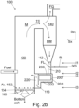
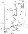
- a loopseal comprises at least two chambers, i.e. a first chamber 210 and a second chamber 220 (see Figs. 2a , 2b , 3a , and 3b ).
- the loopseal if arranged, is arranged downstream from the particle separator 140, but not further downstream than the furnace 130.
- the loopseal forms a part of the circulating fluidized bed boiler 100.
- the circulating fluidized bed boiler 100 comprises the first chamber 210 and the second chamber 220.
- the loopseal is used to prevent the inverse circulation of the bed material fraction, whereby the loopseal is provided in between the particle separator 140 and the furnace 130 such that in use, the bed material fraction flows from the particle separator 140 to the loopseal and from the loopseal to the furnace (not vice versa).
- the first chamber 210 is arranged downstream from the particle separator 140 (but not further downstream than the second chamber 220) in a direction of a flow of the bed material fraction BM
- the second chamber 220 is arranged downstream from the first chamber 210 but not further downstream than the furnace 130 in a direction of a flow of the bed material fraction BM.
- the bed material fraction BM enters the first chamber 210 of the circulating fluidized bed boiler 100 at a first level l1 and exits the first chamber 210 at a second level l2.
- level refers to distance from ground level, thereby determining a height at which the bed material enters/exits the chamber 210, 220.
- the second level l2 is arranged lower than the first level 11.
- the levels l1 and l2 are shown in Figs. 2a to 3b . It is noted that the direction arrow Sz in these figures points upwards, i.e. reverse to gravity.
- the bed material fraction BM enters a second chamber 220 of the circulating fluidized bed boiler 100 at a third level l3 and exits the second chamber 220 at a fourth level l4.
- the fourth level l4 is arranged higher than the third level l3.
- the levels l3 and l4 are shown in Figs. 2a to 3b .
- the bed material fraction is configured to enter and exit the chamber 210, 220 as discussed above.
- the second chamber 220 is arranged upstream from the heat exchanger tube 201 in the direction of a flow of the bed material fraction BM. More specifically, the second chamber 220 is arranged upstream from the heat exchanger tube 201 in the direction of a flow of the bed material fraction BM, but not further upstream than the first chamber 210. To some extent this improves the separation of the bed material fraction already upstream from the heat exchanger tube 201.
- the feeding location FL is arranged in the second chamber 220 (as shown in Fig. 3a ) or in a direction of a flow of the bed material fraction BM, downstream from the second chamber 220 (as shown in Fig. 2a ), but not further downstream than the heat exchanger tube 201.
- the direction “downstream” refers to the direction of flow of the bed material fraction BM.
- the bed material fraction BM is configured to flow substantially downwards in the first chamber 210 and substantially upwards in the second chamber 220. Reference is made to Figs. 2a to 3b .
- the corrosive effect of the alkali chlorides is most prominent at a certain temperature window, which most often would occurs only in a last heat exchanger configured to heat the heat transfer medium.
- the term "last" refers to the direction of flow of heat transfer medium within a circulation of the heat transfer medium. Such circulation is shown e.g. in Fig. 3b , the heat transfer medium therein flowing from the heat exchanger 410 to the heat exchanger 420, therefrom to the heat exchanger 430, and therefrom to the first heat exchanger 200, which is also the last heat exchangers in this circulation.
- the heat transfer medium is conveyed for use; most typically at this stage, the heat transfer medium is superheated steam, which is conveyed to a steam turbine combined with a generator for the production of electricity.
- the first heat exchanger 200 comprising the heat exchanger tube 201 is such a last heat exchanger that no heat exchanger that is arranged to be in contact with flue gas is arranged to a location that is downstream from the first heat exchanger 200 (but not further downstream than a steam turbine, if a steam turbine is used), the term "downstream" here referring to the direction of flow of the heat transfer medium flowing within the circulation of the heat transfer medium.
- the first heat exchanger 200 is also such a last heat exchanger that no other heat exchanger in which in use the steam is at least as hot as in the first heat exchanger 200 is arranged to be in contact with flue gas.
- the system comprises a steam turbine, downstream from the steam turbine the steam may condense and be recirculated back to an economizer, e.g. the heat exchanger 410.
- the heat transfer medium may be cooler, whereby also a temperature of an outer surface of a tube of that heat exchanger may be, in use, cooler than the lower critical temperature, above which the corrosion is most prominent.
- reducing corrosion e.g. by feeding sulphur onto heat exchanger tubes of such other heat exchangers is not needed.
- an embodiment of the method comprises feeding the sulphur-containing reagent R only to the bed material fraction BM (or only to a part of the bed material fraction BM) and only to one or more location(s) that is/are upstream from the heat exchanger tube 201.
- the proper location has been discussed in more specific terms above.
- the reagent R is fed to multiple locations, what has been said above for the feeding location FL applies to each of the multiple locations.
- reagent R or other sulphur-containing reagent
- a fluidized bed boiler is equipped with multiple heat exchanger to effectively recover heat from the flue gases and/or from the bed material and/or received by radiation at the other heat exchanger.
- an embodiment of the method comprises feeding a first amount M1 of the sulphur-containing reagent R to the bed material fraction BM (i.e. the separated bed material), to one or more location(s) that is/are upstream from the heat exchanger tube 201.
- the amount M1 in such a case refers to the total amount of the sulphur-containing reagent R fed to the multiple locations.
- the first amount M1 refers to a rate (e.g. kg/h).
- the first amount M1 may be an average value taken e.g. over an hour of operation.
- an embodiment comprises not feeding the sulphur-containing reagent R to any one of: the flue gas fraction FG, the primary first channel 111, or the furnace 130.
- such an embodiment comprises feeding a second amount M2 of the sulphur-containing reagent R and/or other sulphur-containing reagent to the flue gas fraction FG, the first primary channel 111 and/or the furnace 130, wherein a ratio (M1/M2) of the first amount M1 to the second amount M2 is at least one third 1/3.
- the ratio M1/M2 is at least one, more preferably at least 3.
- a non-zero second amount M2 seems not to have any beneficial technical effect when the operating temperatures are proper. If the sulphur-containing reagent R and/or other sulphur-containing reagent is fed to more than one of the flue gas fraction FG, the first primary channel 111 and/or the furnace 130, the second amount refers to the total amount of the reagent fed to these places.
- the second amount M2 refers to a rate (e.g. kg/h).
- the second amount M2 may be an average value taken e.g. over an hour of operation.
- the second amount M2 is zero (i.e. the sulphur-containing reagent R is not fed to any one of: the flue gas fraction FG, the primary first channel 111, or the furnace 130).
- the circulating fluidized bed boiler 100 comprises a pipeline 412 for conveying heat transfer medium from the second heat exchanger (410, 420, 430) to the first heat exchanger 200, optionally via another heat exchanger.
- the pipeline 412 conveys water/steam also from the heat exchanger 420 to the first heat exchanger 200, via the heat exchanger 430.
- the pipeline 412 conveys water/steam from the heat exchanger 420 to the first heat exchanger 200 directly.
- the pipeline 412 conveys heat transfer medium from the second heat exchanger (410, 420, 430) to the first heat exchanger 200. Because of the pipeline, the second heat exchanger (410, 420, 430) is arranged upstream (in the direction of heat transfer medium circulation) from the first heat exchanger, whereby a temperature of an outer surface of a tube of the second heat exchanger (410, 420, 430) remains sufficiently low.
- a temperature of an outer surface of a second heat exchanger tube of the second heat exchanger (410, 420, 430) of is less than 450 °C. In such a case, the temperature is sufficiently low for not having significant corrosion problems on the an outer surface of a second heat exchanger tube of the second heat exchanger (410, 420, 430).
- a temperature of an outer surface of the heat exchanger tube 201 is more than 450 °C, such as from 450 °C to 750 °C. It is possible to also increase a surface temperature of the heat exchanger tube 201 by applying an insulator 201c, as detailed below.
- an embodiment of the circulating fluidized bed boiler 100 comprises the second heat exchanger (410, 420, 430).
- the second heat exchanger 410, 420 is configured to recover heat from the flue gas fraction FG, as shown in Fig. 3a .
- the second heat exchanger 430 is configured to recover heat from the mixture M as shown in Fig. 3b .
- the fluidized bed boiler 100 may comprise multiple second heat exchangers (410, 420, 430) configured to recover heat from the flue gas fraction FG or from the mixture M, as shown in Fig. 3b .
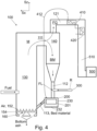
- an embodiment of the circulating fluidized bed boiler 100 comprises a sulphur removal unit 500 and a channel 510 configured to convey the flue gas fraction FG to the sulphur removal 500 unit (see Fig. 4 ).
- a corresponding embodiment of the method comprises removing sulphur from the flue gas fraction FG.
- Sulphur can be removed by from the flue gas fraction means known as such.
- an embodiment comprises removing sulphur oxide (SOx) from the flue gas fraction FG in a wet scrubber.
- the wet scrubber may be comprised by the sulphur removal unit 500.
- the sulphur removal unit 500 may be a wet scrubber.
- An aqueous and alkaline scrubbing solution may be used in the wet scrubber for removing the sulphur oxides.
- the circulating fluidized bed boiler 100 comprises a second heat exchanger (410, 420) configured to recover heat from the flue gas fraction FG to the heat transfer medium; and the second heat exchanger (410, 420) is arranged downstream from the particle separator 140 in the direction of flow of the flue gas fraction FG, but not further downstream than the sulphur removal unit 500.
- a second heat exchanger (410, 420) configured to recover heat from the flue gas fraction FG to the heat transfer medium
- the second heat exchanger (410, 420) is arranged downstream from the particle separator 140 in the direction of flow of the flue gas fraction FG, but not further downstream than the sulphur removal unit 500.
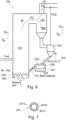
- the corrosion problem of the heat exchanger tube 201 can be further reduced by increasing a temperature of an outer surface of the heat exchanger tube 201. It has been found that the temperature of an outer surface of the heat exchanger tube 201 can be increased by reducing thermal conductivity of the heat exchanger tube 201. This can be done by providing thermal insulation in between the inner and outer surfaces of the heat exchanger tube 201. Therefore, and with reference to Fig. 7 , in an embodiment, the heat exchanger tube 201 comprises an inner tube 201a, an outer tube 201b radially surrounding the inner tube 201a, and thermally insulating material 201c arranged in between the inner tube 201a and the outer tube 201b. Preferably, the thermal conductivity of the thermally insulating material 201c is from 1 W/mK (Watt per metre Kelvin) to 10 W/mK at 20 °C.
- the bed material fraction BM may be fluidized.
- an embodiment of the circulating fluidized bed boiler 100 comprises nozzles 232 configured to fluidize the bed material fraction BM in a vicinity of the heat transfer tube 201.
- the fluidizing of the bed material fraction BM facilitates the flow of the bed material fraction BM.
- the fluidizing gas comprises oxygen O 2
- the fluidizing gas enhances the reactions of the Equations (1) and (2) and in this way helps to reduce the corrosion problems.
- an embodiment comprises fluidizing at least a part of the bed material fraction BM in a vicinity of the heat transfer tube 201 by feeding fluidizing gas, wherein the fluidizing gas comprises oxygen O 2 .
- the fluidizing gas further comprises humidity H 2 O.
- Air may be used as the fluidizing gas.
- oxygen-containing gas may be fed to a location that is arranged downstream from the particle separator 140 but not further downstream than the heat transfer tube 201.
- the oxygen-containing gas may further be used for fluidizing the bed material fraction BM.
- the oxygen-containing gas may comprise humidity (H 2 O).
- the oxygen-containing gas does not comprise a lot of corrosive compounds of the flue gas, because this would increase the consumption of the sulphur-containing reagent R.
- an embodiment of the circulating fluidized bed boiler 100 comprises a first compartment 230, in which the heat exchanger tube 201 is arranged.
- the term "compartment” refers to a space surrounded by walls.
- the nozzles 232 are configured to fluidize the bed material fraction BM in the first compartment 230.
- the nozzles 232 are arranged at a bottom of the first compartment 230.
- fluidizing gas e.g. air
- the means 300 for feeding the sulphur-containing reagent R to the bed material fraction BM may be configured to
- a preferable embodiment comprises:
- nozzles for feeding fluidizing air for improving the bed material circulation may be provided also to other compartments or chambers 210, 220, if considered feasible.
- both the chambers 210, 220 may be provided with such nozzles.
- a bottom of the channel 113 may be provided with such nozzles.
- the fluidizing gas fed through the nozzles 232 may be conveyed with the bed material fraction BM to the furnace through the primary third channel 113 (which may be called a return channel).
- the circulating fluidized bed boiler 100 is provided with an auxiliary channel 115 and an opening 116.
- Nozzles for feeding fluidizing air may be provided at a bottom of the auxiliary channel 115.
- the auxiliary channel 115 may be used to guide some of the bed material to the first heat exchanger 200 from the furnace 130 directly. It may be possible that a content of corrosive compounds at a bottom of the furnace 130 is so low that only a little alkali chlorides of the flue gases pass from the furnace 130 to the heat exchanger 200 through the auxiliary channel 115.
- the opening 116 can be used is some operating conditions for guiding bed material directly from the furnace 130 to the first heat exchanger.
- a part of the bed material in the furnace will not propagate to the particle separator 140, but can be circulated to the first heat exchanger 200 via the opening 116, which may serve the purpose of a particle separator.
- the opening 116 decreases an amount of flue gases near the heat exchanger tube 201 compared to the furnace.
- the bed material circulates at least from the furnace 130 to the particle separator 140, therefrom to the first heat exchanger 200, and therefrom back to the furnace 130. Because the sole purpose of the first heat exchanger 200 is to recover heat, the bed material is not conveyed to the furnace only through the bypass opening 115.
- the first heat exchanger 200 only receives bed material through the particle separator 140.
- no other bed material than the bed material fraction BM that has been separated in the particle separator 140 is conveyed to the first heat exchanger 200.
- the heat transfer tube 201 not all the separated bed material needs to be conveyed to the heat transfer tube 201.
- Fluidizing gas fed through the nozzles 232 may be conveyed with the bed material fraction BM to the furnace 130 through the primary third channel 113 (which may be called a return channel).
- the auxiliary channel 115 could be used, in the alternative, to expel bed material fraction BM from the heat exchanger 200 so that the bed material fraction BM or a part of the bed material fraction BM bypasses the heat exchanger tube 201. It may be beneficial to be able to let a part of the bed material fraction BM bypass the heat exchanger tube 201, because the temperature of the heat transfer medium downstream from the first heat exchanger 200 (in the direction of the flow of the heat transfer medium) needs often be carefully controlled.
- a suitable heat exchanger having a bypass reference is made to the publications WO 2018/083367 , WO 2019/122509 , and US5184671 , incorporated herein by reference.
- the loopseal heat exchangers presented therein can be used as the first heat exchanger 200 of the present invention.
- a heat exchanger of the publication WO 2018/083367 is used, preferably the sulphur-containing reagent R is fed to the feeding chamber 150 of the heat exchanger of Fig. 2a of the publication WO 2018/083367 .
- the sulphur-containing reagent R may be fed e.g. to the inlet chamber 100 of the heat exchanger of any one of Figs.
- the reagent R is fed to the feeding chamber 100 of Fig. 2 of the publication WO 2019/122509 or to the channel 60 of Fig. 1 of the publication WO 2019/122509 .
- a heat exchanger of the publication US5184671 is used, preferably the reagent R is fed to the feeding chamber A of the heat exchanger of the Figs. 1 to 3 of the publication US5184671 .
- the reagent R may be fed e.g.
- the reagent R is fed to the feeding upleg 102 of the heat exchanger of the Figs. 4a to 5b the publication WO2019/086752 .
- the reagent R may be fed e.g. to the dip leg 100 of the publication WO2019/086752 .
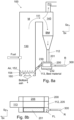
- the circulating fluidized bed boiler 100 comprises a bypass 206 (see Figs. 8a and 8b ) that is configured to guide a part of the bed material fraction BM from the particle separator 140 to the furnace 130 (e.g. via the primary third channel 113 of Figs. 8a and 8b ) such that the part of the bed material fraction BM that travels through the bypass 206 does not come into contact with the heat exchanger tube 201.
- the circulating fluidized bed boiler 100 comprises the bypass 206
- the circulating fluidized bed boiler 100 comprises a splitting chamber 205 configured to guide a first part of the bed material fraction BM to the heat exchanger tube 201 and a second part to the bypass 206.
- a splitting chamber 205 is shown also in Fig. 8b .
- the primary second channel 112 extends downwards (in the negative Sz direction) to the splitting chamber 205, which splits the bed material fraction to two parts.
- the splitting chamber 205 divides the bed material fraction to the first part, which is conveyed to the heat transfer tube 201 (i.e. onto the heat transfer tube 201, as the water/steam propagates in the tube).
- the second part flows through the bypass 206.
- the division of the bed material to the first and second parts can be controlled by fluidizing gas feed as detailed e.g. in the cited publications.
- the sulphur-containing reagent R is fed to the first part of the bed material fraction BM and downstream from the splitting chamber 205 (or into the splitting chamber 205), but not further downstream than the heat exchanger tube 201.
- the feeding location FL is, in an embodiment, arranged in the splitting chamber 205 or downstream from the splitting chamber 205, but not further downstream than the heat exchanger tube 201.
- the feeding location FL is, in an embodiment, arranged such that the sulphur-containing reagent R is fed to the first part of the bed material fraction (i.e. not conveyed to the bypass 206).
- an embodiment comprises dividing the bed material fraction BM to a first part and a second part using a splitting chamber, guiding the first part of the bed material fraction to the to the heat exchanger tube 201, guiding the second part of the bed material fraction through a bypass 206 so that the second part of bed material fraction BM does not come into contact with the heat exchanger tube 201, and feeding the sulphur-containing reagent R to the splitting chamber 205 or downstream from the splitting chamber 205, but not further downstream than the heat exchanger tube 201.
- the bypass 206 may be arranged as a part of the heat exchanger 200 is detailed in the publications listed above and in Fig. 8b . In the alternative, a bypass may be arranged in parallel with the heat exchanger 200.
- the fluidized bed boiler may comprise a first particle separator 140 and a second particle separator 142 in cascade. This has the effect that each particle separator removes some flue gas from the bed material.
- the first particle separator 140 separates a first flue gas fraction FG and the bed material fraction.
- the second particle separator 142 separates a second flue gas fraction FG2 and a bed material fraction.
- the flue gas fractions FG, FG2 from each separator 140, 142 may be conveyed to a secondary first channel 121, which conveys the flue gas fractions away from the furnace 130.
- the flue gas fractions FG, FG2 may be conveyed e.g.
- the sulphur-containing reagent R is preferably fed to a location that is arranged at a lower part of a last particle separator or downstream from the last particle separator.
- last particle separator refers to such a particle separator that is most downstream in the direction of flow of the bed material. Such a last particle separator is shown by the reference 142 in Fig. 6 . However, it may happen that some other particle separator, e.g. the particle separator 140 of Fig.
- the sulphur-containing reagent R may be fed to a location that is arranged at a lower part of one of the particle separators (e.g. 140, even if 142 is present) or downstream from one of the particle separators (e.g. 140, even if 142 is present).
Landscapes
- Engineering & Computer Science (AREA)
- Mechanical Engineering (AREA)
- General Engineering & Computer Science (AREA)
- Chemical & Material Sciences (AREA)
- Combustion & Propulsion (AREA)
- Physics & Mathematics (AREA)
- Thermal Sciences (AREA)
- Health & Medical Sciences (AREA)
- Biomedical Technology (AREA)
- Environmental & Geological Engineering (AREA)
- Analytical Chemistry (AREA)
- General Chemical & Material Sciences (AREA)
- Oil, Petroleum & Natural Gas (AREA)
- Chemical Kinetics & Catalysis (AREA)
- Fluidized-Bed Combustion And Resonant Combustion (AREA)
Abstract
Description
- The invention relates to fluidized bed boilers of the circulating type. The invention relates to methods for operating a circulating fluidized bed boilers. The invention relates to methods for reducing corrosion of fluidized bed heat exchangers.
- Boilers are used to produce steam by burning fuel. The steam can be used for heating and/or for producing mechanical energy in a turbine, which may be converted to electricity. In combustion, some compounds of the fuel are released or reacted to produce flue gas. Some compounds of the flue gas corrode the heat transfer surfaces of the boiler, which reduces service life and increases maintenance needs.
- To this end, it is known that the corrosive compounds are most corrosive at a certain temperature window in a molten form. Thus, to avoid corrosion, a surface temperature of a heat transfer tube can be, in some cases, arranged to be above a higher critical temperature or below a lower critical temperature. Such critical temperatures may be e.g. about 450 °C and about 750 °C, respectively. However, precise values of these critical temperatures depend on the composition of the flue gas, which depends on the fuel that is used. To further reduce corrosion, it is known to apply different types of coatings onto heat transfer surfaces.
- However, nowadays the needed steam temperature has gone up, and the content of the fuel has changed so as to form such compounds, mainly alkali chlorides, that are comprised in the smelt form on heat transfer surfaces in typical use. Particularly some types of fuel comprises a lot of chlorine, which seems to pose corrosion problems. Therefore, other solutions are required in addition or alternatively.
- It has been found that corrosion can be reduced by feeding sulphur-containing reagent to the process. The sulphur-containing reagent may be e.g. elementary sulphur or in a form of a sulphate. However, in line with the background, it has also been found that sulphur-containing reagent needs not be fed to such heat exchange surfaces that a reasonably cool, i.e. so cool that the alkali chlorides are not in a form of a smelt therein. Moreover, it has been found that when high-temperature steam needs to be produced, the high-temperature superheater(s) can be arranged to such a location in which there is only a minor amount of the corrosive components. Thus, a lesser amount of sulphur-containing reagent is needed compared to feeding to some other locations. It has been found that in a circulating fluidized bed boiler, such a location is arranged after a particle separator, which separates a flue gas fraction and a bed material fraction; whereby most of the corrosive components flow with the flue gas fraction. Correspondingly the bed material fraction comprises only a minor amount of the corrosive compounds. Therefore, the high-temperature heat exchanger (hereinafter a first heat exchanger) is configured to recover heat from the bed material fraction, and the sulphur-containing reagent is fed upstream from a heat transfer tube of the first heat exchanger, to the bed material fraction (i.e. downstream from the separation of the bed material fraction). At such a location only a minor amount of corrosive compounds would be present without the sulphur addition, because of the separation of the flue gas fraction, and with the sulphur addition, the amount of corrosive compounds decreases even further.
- The invention is disclosed in more specific terms in the independent claims 1 and 9. Preferable embodiments are disclosed in dependent claims. These and other embodiments are explained and disclosed in the description and the figures.
-
- Fig. 1
- shows a circulating fluidized bed boiler and feeding sulphurcontaining reagent to the circulating fluidized bed boiler,
- Fig. 2a
- shows a circulating fluidized bed boiler having a loopseal and feeding sulphur-containing reagent to the circulating fluidized bed boiler,
- Fig. 2b
- shows a circulating fluidized bed boiler having a loopseal and feeding sulphur-containing reagent to the circulating fluidized bed boiler,
- Fig. 3a
- shows a circulating fluidized bed boiler having other heat exchangers and circulation of heat transfer medium therein,
- Fig. 3b
- shows a circulating fluidized bed boiler having other heat exchangers and circulation of heat transfer medium,
- Fig. 3c
- shows a circulating fluidized bed boiler having other heat exchangers and circulation of heat transfer medium,
- Fig. 4
- shows a circulating fluidized bed boiler connected to a sulphur removal device, such as a scrubber,
- Fig. 5
- shows another circulating fluidized bed boiler and feeding sulphurcontaining reagent to the circulating fluidized bed boiler,
- Fig. 6
- shows a circulating fluidized bed boiler having two particle separators in a cascade,
- Fig. 7
- shows a cross section of a heat transfer tube having an inner tube, an outer tube, and insulator in between,
- Fig. 8a
- shows in a side view a circulating fluidized bed boiler having a loopseal heat exchanger with a bypass and feeding sulphurcontaining reagent to the loopseal heat exchanger, and
- Fig. 8b
- shows in a top view the loopseal heat exchanger of
Fig. 8a and feeding sulphur-containing reagent to the loopseal heat exchanger. -
Figure 1 shows afluidized bed boiler 100. The fluidized bed boiler is of the circulating type. Even when not in use, such a fluidized bed boiler may be called a circulating fluidized bed boiler. A purpose of a boiler is to recover heat and to produce steam. Therefore, the circulating fluidized bed boiler comprises afirst heat exchanger 200 comprising aheat exchanger tube 201. In use, heat transfer medium (in an embodiment water/steam) is fed into theheat exchanger tube 201 and heat received by an outer surface of theheat exchanger tube 201 is transferred to the heat transfer medium. In this way, heat is recovered to the heat transfer medium. - The heat that is recovered is produced by combustion. Therefore, fuel and air are fed to a
furnace 130 of the circulatingfluidized bed boiler 130. In addition, bed material is fed to thefurnace 130. Bed material may be supplied from areturn channel 113; and in addition additional bed material may be added e.g. with the fuel and/or to thereturn channel 113 and/or through other means (not shown). - Fluidizing air is supplied through
nozzles 152 to the furnace. In a circulatingfluidized bed boiler 100 so much air is supplied that the fuel and the bed material fluidizes, and they flow, with the air, as a mixture M comprising the air, fuel, and bed material towards aparticle separator 140. Typically, the mixture M flows in thefurnace 130 substantially upwards. InFig. 1 , the direction Sz is upwards, i.e. reverse to gravity. Because thefurnace 130 is hot, the fuel burns thereby producing heat, ash, and flue gas. Thus, in thefurnace 130, the mixture M comprises at least bed material and gas (air and/or flue gas). The directions Sx and Sy are perpendicular to Sz and to each other. - In
Fig. 1 , the air is fed to thenozzles 152 throughwindboxes 154. InFig. 1 , in between thewindboxes 154,channels 160 for removing bottom ash are arranged. Bottom ash may be removed through thechannels 160 in use, because otherwise the ash resulting from combustion accumulates to the bed material. However, bottom ash may be removed in addition or in the alternative from the heat exchanger 200 (such ash removal not shown inFig. 1 ). - The
particle separator 140 is configured to separate from the mixture M, which comprises at least bed material and flue gas, both a bed material fraction BM and a flue gas fraction FG. The flue gas fraction FG is conveyed (optionally through cleaning phases) eventually to a chimney. The bed material fraction BM is circulated back to thefurnace 130. However, as detailed below, heat is recovered from at least part of the bed material fraction BM using thefirst heat exchanger 200. The bed material as well as the bed material fraction BM comprises solid particulate material that is heat resistant, such as sand. In use, at least a part of a bed material fraction BM is guided to (i.e. onto) theheat exchanger tube 201 so that heat is recovered from the part of the bed material fraction. - As detailed in the background, burning the fuel results in such flue gases that are corrosive at least within a certain temperature window. It has been found that typically alkali chlorides are very corrosive at a temperature window of about 450 °C to about 700 °C or even up to 750 °C. A rate of corrosion depends also on a content of the corrosive compounds in the flue gases. Thus, when a steam temperature inside the heat exchanger tube is more than 400 °C (e.g. around 500 °C) and the environment is hotter, such conditions easily occur on outer surface of the
heat transfer tube 201. Moreover, even if at a higher temperature the corrosiveness goes down, the gases may be somewhat corrosive. Thus, reducing corrosion also by other means is needed at least at such locations. - It has been found that alkali chlorides can be captured by feeding sulphur. More precisely, the alkali chlorides react with sulphur oxide (SOx) to form alkali sulphate, which is less corrosive than alkali chloride. Some of the relevant reactions can be expressed as:
2MaCl + SO2 + ½O2 + H2O → Ma 2SO4 + 2 HCl (1)
2MaCl + SO3 + H2O → Ma 2SO4 + 2 HCl (2)
, wherein Ma is an alkali ion (e.g. Na or K). - In the hot environment of the furnace, substantially all sulphur-containing materials react with oxygen to form SO2 (or other SOx), which is needed in the reaction (see the reaction above). Moreover, the alkali sulphate Ma 2SO4 is much less corrosive than the alkali chloride MaCl. Moreover, the hydrogen chloride is in the gaseous form, whereby it also is not corrosive.
- Feeding large amounts of sulphur is expensive and results in other problems, mainly the production of excess sulphur oxides. The inventors have found that most of the corrosive alkali chlorides do not enter the bed material fraction BM, because the most of the alkali chlorides flow with the flue gas fraction FG away from the heat exchanger tube 201 (see
Fig. 1 ). Thus, if thefirst heat exchanger 200 in which the steam temperature is high (see above) is configured to recover heat from the only bed material fraction BM (or a part thereof), the sulphur-containing reagent R can be fed to the bed material fraction BM, from which most of the flue gas have been removed by the particle separator. However, the sulphur-containing reagent R should be fed upstream from thefurnace 130, because in thefurnace 130, flue gases are generated again. Thus, to convert the chloride to the sulphate before theheat exchanger tube 201 of the first heat exchanger, the sulphur-containing reagent R is fed upstream from theheat exchanger tube 201. - It is noted that as an alternative to a sulphur-containing reagent R, from the technical point of view aluminium silicates also are capable of reducing corrosion problems. Thus, as an alternative to sulphur-containing reagent R, a reagent comprising only aluminium silicates can be fed using the same principles as detailed in this description. However, the inventors have noticed that a sulphur-containing reagent R functions much better, and the operational costs remain at a much lower level when a sulphur-containing reagent R is used instead of aluminium silicates. However, the sulphur-containing reagent R of the present invention may comprise, in addition to a sulphur compound, e.g. aluminium silicate.
- Hereinbelow, unless otherwise indicated, the terms "upstream" and "downstream" refer to the bed material circulation defined by the following components of the fluidized bed boiler: the
particle separator 140, thefirst heat exchanger 200, and the furnace. The bed material (or a part thereof) flows from theparticle separator 140 to thefirst heat exchanger 200; from thefirst heat exchanger 200 to thefurnace 130; and from thefurnace 130 to the particle separator 140 (seeFigs. 1 to 6 ). As will be detailed below, downstream from the particle separator, a splitting chamber may divide the bed material fraction BM to a first part and a second part such that only the first part is conveyed to theheat transfer tube 201, while the second part bypasses theheat transfer tube 201. - Moreover, because of the role of alkali chlorides, the method is particularly useful when such a fuel that has a high content of chlorine is burnt. Typically fuels derived from residue comprise a lot of chlorine. Correspondingly, the method and the
fluidized bed boiler 100 are particularly useful with such a fuel. - Thus, in an embodiment of the method, the fuel comprises a component derived from residue. In an embodiment, the fuel comprises biodegradable material and/or plastic material. In an embodiment, the fuel comprises at least one of refuse derived fuel (RDF), recovered fuel (REF), and solid recovered fuel (SRF). Correspondingly, in an embodiment, the
fluidized bed boiler 100 comprises means for feeding such fuel that has been derived from residue into thefurnace 130. - Thus, an embodiment of a method for operating a circulating fluidized bed boiler comprises feeding air ("Air" in
Fig. 1 ), fuel ("Fuel" inFig 1 ), and bed material ("Bed material" inFig. 1 ) to afurnace 130 of the circulatingfluidized bed boiler 100 and combusting the fuel in thefurnace 130. As a result of the combustion, flue gas is produced. The method comprises conveying a mixture M comprising the flue gas and the bed material from thefurnace 130 to aparticle separator 140 and separating from the mixture M both (i) a bed material fraction BM and (ii) a flue gas fraction FG. The bed material fraction BM and the flue gas fraction FG are separated with theparticle separator 140. The method comprises conveying at least a part of the bed material fraction BM from the particle separator to afirst heat exchanger 200 comprising aheat exchanger tube 201, and recovering heat from the at least part of the bed material fraction BM with theheat exchanger tube 201. As indicated above, theheat exchanger tube 201 is arranged upstream from thefurnace 130. More specifically, theheat exchanger tube 201 is arranged upstream from thefurnace 130 in the direction of bed material flow, but not further upstream from thefurnace 130 than theparticle separator 140. In other words, theheat transfer tube 201 is arranged, in the direction of flow of the bed material fraction in the bed material circulation between theparticle separator 140 and thefurnace 130 to such a location that a distance betweenheat transfer tube 201 and theparticle separator 140 is less than a distance between thefurnace 130 and theparticle separator 140, wherein the distances are measured along a path that starts from theparticle separator 140, runs from theparticle separator 140 along the path the bed material flows, and ends to theparticle separator 140 after one full round. - As shown in
Fig. 1 , thetransfer tube 201 is arranged upstream from thefurnace 130 and downstream from theparticle separator 140. Moreover, in the direction of flow of the bed material fraction in the bed material circulation, the theheat transfer tube 201 is arranged between theparticle separator 140 and thefurnace 130. However, theheat transfer tube 201 is not arranged in the primaryfirst channel 111, which is arranged upstream from the particle separator. Therefore, theheat transfer tube 201 is arranged to such a location as discussed above. E.g. inFig. 1 the distance of theheat transfer tube 201 from theparticle separator 140 is about 1/6 of a full round. However, a distance of thefurnace 130 from the particle separator 140 (as defined above) is about a third of a full round. Moreover, if the heat exchanger tube was arranged in the primaryfirst channel 111 after thefurnace 130, the distance would be at least 5/6 of a full round. - In line with these measures, the
heat exchanger tube 201 is arranged upstream from thefurnace 130 in the direction of bed material flow, but not further upstream from thefurnace 130 than theparticle separator 140. - When the flue gas fraction FG and the bed material fraction are separated from the mixture M, typically only about 1 % to 5 % of the flue gases flow with bed material fraction BM. This indicates why it is much more efficient to feed the reagent R to the material fraction BM than e.g. to the
furnace 130 or to the flue gas fraction FG. - An embodiment of the method comprises conveying only a part of the bed material fraction BM from the
particle separator 140 toheat exchanger tube 201. In this case, the other part may be conveyed through a bypass 206 (seeFig. 8b ). However, in an embodiment and/or at least at certain point of time, an embodiment comprises conveying all the bed material fraction BM from theparticle separator 140 to a heat exchanger comprising theheat exchanger tube 201. - An embodiment of the method comprises conveying only a part of the bed material fraction BM from the
heat exchanger tube 201 to thefurnace 130. In this embodiment, another part of the bed material fraction BM may be removed from the circulation e.g. from theheat exchanger 200 e.g. to a bottom ash cooler for further processing (not shown). An embodiment of the method comprises conveying the whole bed material fraction BM from theheat exchanger tube 201 to thefurnace 130. In this embodiment, a part of the bed material (i.e. the bottom ash) may be removed from thefurnace 130 as detailed above. - To convert the alkali chlorides to alkali sulphates upstream from the
heat exchanger tube 201, the method comprises feeding the sulphur-containing reagent R to the bed material fraction BM upstream from theheat exchanger tube 201. More specifically, the method comprises feeding the sulphur-containing reagent R to the bed material fraction BM upstream from theheat exchanger tube 201, but not further upstream than theparticle separator 140. What has been said about the term "upstream" applies. - Referring to
Fig. 1 , in use, the bed material (or a part thereof) runs from theparticle separator 140 through a primarysecond channel 112 to theheat exchanger tube 201, and through a primarythird channel 113 at least a part thereof runs to thefurnace 130. In thefurnace 130 the mixture comprising the bed material forms and flow to and through a primaryfirst channel 111 in this way ending up again to theparticle separator 140. The primaryfirst channel 111 may be an opening in a wall of thefurnace 130 allowing for the mixture to travel to the particle separator 140 (seeFig. 5 ). The primarythird channel 113 may be an opening in a wall of thefurnace 130 allowing for the bed material fraction, optionally together with fluidizing gas fed to aheat exchanger 200, to travel from theheat exchanger 200 to the furnace 130 (seeFig. 3c ). - An embodiment of a
fluidized bed boiler 100 comprises afurnace 130, in which a fluidized bed comprising a mixture M of solid bed material and gas (air and/or flue gas) is configured to form in use. Thefluidized bed boiler 100 comprises aparticle separator 140, which is configured to separate from the mixture M, (i) the solid bed material fraction BM and (ii) the flue gas fraction FG. Thefluidized bed boiler 100 comprises the primaryfirst channel 111 configured to convey the mixture M from thefurnace 130 to theparticle separator 140. - In order to recover heat from the bed material fraction BM or the part thereof, the fluidized bed boiler comprises the
first heat exchanger 200 comprising theheat exchanger tube 201. What has been said about the location of theheat exchanger tube 201 in connection with the method, applies. Moreover, as detailed above, theheat exchanger tube 201 is configured to recover heat from the bed material fraction BM or the part thereof. Therefore, the fluidized bed boiler comprises a primarysecond channel 112 configured to convey at least a part of the bed material fraction BM from theparticle separator 140 to thefirst heat exchanger 200. - Moreover, to return at least a part of the bed material to the
furnace 130, the fluidized bed boiler comprises a primarythird channel 113, which is configured to convey at least a part of the bed material fraction BM from thefirst heat exchanger 200 to thefurnace 130. What has been said about conveying a part directly to a bottom ash cooler from theheat exchanger 200 in connection with the method applies. - In order to feed the sulphur-containing reagent R to such a location detailed above, the
fluidized bed boiler 100 comprisesmeans 300 for feeding a sulphur-containing reagent R to the bed material fraction BM upstream from theheat exchanger tube 201. - In an embodiment, the
particle separator 140 comprises a cyclone. In an embodiment, theparticle separator 140 is a cyclone. This has the benefit that theparticle separator 140 can be continuously operated at a high temperature. Filters, such as perforated plates, e.g. perforated metal plates, could be used for the purpose of separating bed material and flue gas from their mixture in addition or as an alternative to the cyclone. - Even if the method is defined as being a method for operating a circulating fluidized bed boiler, the method is also a method for reducing corrosion of a fluidized bed heat exchanger of a circulating fluidized bed boiler, because the
first heat exchanger 200 is a fluidized bed heat exchanger. As detailed below, a (bubbling) fluidized bed comprising the bed material fraction BM (or the part of the bed material fraction) may be arranged at a vicinity of theheat exchanger tube 201. - Concerning the sulphur-containing reagent R and, correspondingly, the
means 300 for feeding the reagent, in an embodiment, the sulphur-containing reagent R comprises at least one of elementary sulphur (S) and a sulphate (i.e. a compound comprising the ion SO4 2-). Elementary sulphur may be used in solid form, e.g. in the form of granules or powder. As for the sulphates, they may be supplied in liquid form. However, it has been found that ferric sulphate (Fe2(SO4)3) increases agglomeration of the particles of the bed material fraction BM. Therefore, if a sulphate is used as or in the reagent R, preferably, the sulphate is not ferric sulphate. As for the sulphates, diethyl sulphate ((C2H5)2SO4) and/or dimethyl sulphate ((CH3)2SO4 are most preferable. However, in general, elementary sulphur is even more preferable, as it is cheaper to use. Therefore, in an embodiment, the sulphur-containing reagent R comprises at least one of elementary sulphur S and a sulphate that is not ferric sulphate, e.g. diethyl sulphate ((C2H5)2SO4) or dimethyl sulphate ((CH3)2SO4). More preferably, the sulphur-containing reagent R comprises solid elementary sulphur (S). All these compounds produce sulphur oxide SOx (e.g. SO2 and/or SOs, see Eqns. 1 and 2) in the hot environment. - Solid elementary sulphur, e.g. in the form of granules and/or powder, may be fed to the
fluidized bed boiler 100 through a pipeline. A carrier gas, such as air, may be used to facilitate feeding. For these reasons, in an embodiment, themeans 300 for feeding the sulphur-containing reagent R is configured to feed the sulphur-containing reagent R in a form of solid granules and/or powder. In a preferable embodiment, themeans 300 for feeding the sulphur-containing reagent R is configured to feed the sulphur-containing reagent R in a form of solid granules and/or powder by using a carrier gas, e.g. air, with which the solid granules and/or powder flow to a feeding location FL. In this embodiment, themeans 300 comprises a pipeline configured to convey the granules and/or the powder. In addition or as an alternative to the carrier gas, transfer of the granules and/or powder within themeans 300 may be facilitated by a conveyor, e.g. a conveyor screw. Thus, in an embodiment, themeans 300 for feeding the sulphur-containing reagent R comprises a pipeline. In an embodiment, themeans 300 for feeding the sulphur-containing reagent R comprises a conveyor, such as a screw conveyor. - Referring to
Figs. 1 to 6 and8b , the sulphur-containing reagent R is fed to a feeding location FL. Correspondingly, themeans 300 for feeding the sulphur-containing reagent R is configured to feed the sulphur-containing reagent R to the feeding location FL. - Typically the
particle separator 140, e.g. a cyclone, functions in such a way that the separated bed material fraction BM accumulates to and/or escapes from theparticle separator 140 to/from a lower part of theparticle separator 140. Correspondingly, the reagent R can be fed [i] downstream from theparticle separator 140, but not further downstream than theheat exchanger tube 201 and/or [ii] to a lower part of theparticle separator 140. Therefore, in an embodiment of thefluidized bed boiler 100, the feeding location FL is arranged in a lower part of theparticle separator 140 or in a direction of a flow of the bed material fraction BM, downstream from theparticle separator 140 and upstream from theheat exchanger tube 201. As detailed above, theheat exchanger tube 201 is arranged upstream from thefurnace 130. More specifically, the feeding location FL is arranged as follows: - [A] in a lower part of the
particle separator 140, or - [B,i] in a direction of a flow of the bed material fraction BM, downstream from the
particle separator 140, but not further downstream from theparticle separator 140 than theheat exchanger tube 201 and - [B,ii] in a direction of a flow of the bed material fraction BM, upstream from the
heat exchanger tube 201, but not further upstream from theheat exchanger tube 201 than the lower part of theparticle separator 140. - Naturally, a part of the reagent R may be supplied to the lower part of the particle separator 140 (see option [A] above) and another part or other parts may be supplied between the
particle separator 140 and the heat exchanger tube 201 (see option [B] above). - In terms of distances along the flow path of the bed material, the feeding location FL is arranged [A] in a lower part of the
particle separator 140 or [B] such that in the direction of flow of the bed material fraction in the bed material circulation between theparticle separator 140 and the furnace 130 a distance between feeding location FL and theparticle separator 140 is less than a distance between theheat transfer tube 201 and theparticle separator 140, wherein the distances are measured along a path that starts from theparticle separator 140, runs from theparticle separator 140 along the path the bed material flows, and ends to theparticle separator 140 after one full round. - As detailed above, the consumption of the sulphur-containing reagent R is diminished because the reagent R is fed only to the separated bed material fraction BM, which comprises only a little flue gas, and thereby only a little alkali chlorides. Referring specifically to
Figs. 2a and2b , the separation of bed material fraction BM and flue gas fraction FG can be enhanced by providing the circulatingfluidized bed boiler 100 with a loopseal. In general, a loopseal is used in circulating fluidized bed systems to convey particles from a low pressure region to a high pressure region. One of the principal functions of a loopseal is to avoid the undesirable inverse gas/particle flow and to provide gas tightness. Typically, a loopseal comprises at least two chambers, i.e. afirst chamber 210 and a second chamber 220 (seeFigs. 2a ,2b ,3a , and3b ). To ensure proper circulation of bed material fraction, the loopseal, if arranged, is arranged downstream from theparticle separator 140, but not further downstream than thefurnace 130. - The loopseal forms a part of the circulating
fluidized bed boiler 100. Thus in an embodiment, the circulatingfluidized bed boiler 100 comprises thefirst chamber 210 and thesecond chamber 220. Moreover, the loopseal is used to prevent the inverse circulation of the bed material fraction, whereby the loopseal is provided in between theparticle separator 140 and thefurnace 130 such that in use, the bed material fraction flows from theparticle separator 140 to the loopseal and from the loopseal to the furnace (not vice versa). Therefore, thefirst chamber 210 is arranged downstream from the particle separator 140 (but not further downstream than the second chamber 220) in a direction of a flow of the bed material fraction BM, and thesecond chamber 220 is arranged downstream from thefirst chamber 210 but not further downstream than thefurnace 130 in a direction of a flow of the bed material fraction BM. - Concerning an embodiment of the method, i.e. in a use of the circulating
fluidized bed boiler 100, the bed material fraction BM enters thefirst chamber 210 of the circulatingfluidized bed boiler 100 at a first level l1 and exits thefirst chamber 210 at a second level l2. The term "level" refers to distance from ground level, thereby determining a height at which the bed material enters/exits thechamber first level 11. The levels l1 and l2 are shown inFigs. 2a to 3b . It is noted that the direction arrow Sz in these figures points upwards, i.e. reverse to gravity. Furthermore, in use, the bed material fraction BM enters asecond chamber 220 of the circulatingfluidized bed boiler 100 at a third level l3 and exits thesecond chamber 220 at a fourth level l4. The fourth level l4 is arranged higher than the third level l3. The levels l3 and l4 are shown inFigs. 2a to 3b . - Concerning an embodiment of the circulating fluidized bed boiler, the bed material fraction is configured to enter and exit the
chamber - In a preferable embodiment, as shown in
Figs. 2a ,3a , and3b , thesecond chamber 220 is arranged upstream from theheat exchanger tube 201 in the direction of a flow of the bed material fraction BM. More specifically, thesecond chamber 220 is arranged upstream from theheat exchanger tube 201 in the direction of a flow of the bed material fraction BM, but not further upstream than thefirst chamber 210. To some extent this improves the separation of the bed material fraction already upstream from theheat exchanger tube 201. - Preferably, in such an embodiment, the feeding location FL is arranged in the second chamber 220 (as shown in
Fig. 3a ) or in a direction of a flow of the bed material fraction BM, downstream from the second chamber 220 (as shown inFig. 2a ), but not further downstream than theheat exchanger tube 201. The direction "downstream" refers to the direction of flow of the bed material fraction BM. - Concerning the position of the
chambers first chamber 210 and substantially upwards in thesecond chamber 220. Reference is made toFigs. 2a to 3b . - As detailed above, the corrosive effect of the alkali chlorides is most prominent at a certain temperature window, which most often would occurs only in a last heat exchanger configured to heat the heat transfer medium. Herein the term "last" refers to the direction of flow of heat transfer medium within a circulation of the heat transfer medium. Such circulation is shown e.g. in
Fig. 3b , the heat transfer medium therein flowing from theheat exchanger 410 to theheat exchanger 420, therefrom to theheat exchanger 430, and therefrom to thefirst heat exchanger 200, which is also the last heat exchangers in this circulation. After the last heat exchanger, the heat transfer medium is conveyed for use; most typically at this stage, the heat transfer medium is superheated steam, which is conveyed to a steam turbine combined with a generator for the production of electricity. - Thus, in an embodiment, the
first heat exchanger 200 comprising theheat exchanger tube 201 is such a last heat exchanger that no heat exchanger that is arranged to be in contact with flue gas is arranged to a location that is downstream from the first heat exchanger 200 (but not further downstream than a steam turbine, if a steam turbine is used), the term "downstream" here referring to the direction of flow of the heat transfer medium flowing within the circulation of the heat transfer medium. Thus, in such a case, thefirst heat exchanger 200 is also such a last heat exchanger that no other heat exchanger in which in use the steam is at least as hot as in thefirst heat exchanger 200 is arranged to be in contact with flue gas. Naturally, when the system comprises a steam turbine, downstream from the steam turbine the steam may condense and be recirculated back to an economizer, e.g. theheat exchanger 410. - In other words, in such heat exchangers that are arranged upstream from the last heat exchanger (in the direction of flow of the heat transfer medium), the heat transfer medium may be cooler, whereby also a temperature of an outer surface of a tube of that heat exchanger may be, in use, cooler than the lower critical temperature, above which the corrosion is most prominent. Reference is made to the section "Background". Notable, reducing corrosion e.g. by feeding sulphur onto heat exchanger tubes of such other heat exchangers is not needed. Correspondingly feeding the sulphur-containing reagent R only to one or more locations as discussed above reduces the consumption of the reagent R. Thus, an embodiment of the method comprises feeding the sulphur-containing reagent R only to the bed material fraction BM (or only to a part of the bed material fraction BM) and only to one or more location(s) that is/are upstream from the
heat exchanger tube 201. The proper location has been discussed in more specific terms above. In case the reagent R is fed to multiple locations, what has been said above for the feeding location FL applies to each of the multiple locations. - Naturally, a minor amount of the reagent R (or other sulphur-containing reagent) can be fed also elsewhere, but that seems not to have a technical effect on corrosion, at least provided that the temperature window of the other heat transfer surfaces remain outside the temperature window, in particular lower than the lower critical temperature. Furthermore, typically a fluidized bed boiler is equipped with multiple heat exchanger to effectively recover heat from the flue gases and/or from the bed material and/or received by radiation at the other heat exchanger.
- Thus, an embodiment of the method comprises feeding a first amount M1 of the sulphur-containing reagent R to the bed material fraction BM (i.e. the separated bed material), to one or more location(s) that is/are upstream from the
heat exchanger tube 201. In case the reagent R is fed to multiple locations, what has been said above for the feeding location FL applies to each of the multiple locations. Moreover, the amount M1 in such a case refers to the total amount of the sulphur-containing reagent R fed to the multiple locations. The first amount M1 refers to a rate (e.g. kg/h). The first amount M1 may be an average value taken e.g. over an hour of operation. - Moreover, as detailed above, an embodiment comprises not feeding the sulphur-containing reagent R to any one of: the flue gas fraction FG, the primary
first channel 111, or thefurnace 130. - However, if, for some reason, some sulphur-containing reagent (same reagent R or other reagent) was fed elsewhere, preferably that amount would not be significant compared to the first amount M1. More specifically, such an embodiment comprises feeding a second amount M2 of the sulphur-containing reagent R and/or other sulphur-containing reagent to the flue gas fraction FG, the first
primary channel 111 and/or thefurnace 130, wherein a ratio (M1/M2) of the first amount M1 to the second amount M2 is at least one third 1/3. - Preferably the ratio M1/M2 is at least one, more preferably at least 3. As detailed above, a non-zero second amount M2 seems not to have any beneficial technical effect when the operating temperatures are proper. If the sulphur-containing reagent R and/or other sulphur-containing reagent is fed to more than one of the flue gas fraction FG, the first
primary channel 111 and/or thefurnace 130, the second amount refers to the total amount of the reagent fed to these places. The second amount M2 refers to a rate (e.g. kg/h). The second amount M2 may be an average value taken e.g. over an hour of operation. - However, feeding a lot of sulphur to the fluidized bed boiler has the disadvantage of increasing the need for removing sulphur from the flue gas fraction FG. Therefore, preferable the second amount M2 is zero (i.e. the sulphur-containing reagent R is not fed to any one of: the flue gas fraction FG, the primary
first channel 111, or the furnace 130). - To have a suitably low temperature at a surface of the second heat exchanger (410, 420, 430) the circulating
fluidized bed boiler 100 comprises apipeline 412 for conveying heat transfer medium from the second heat exchanger (410, 420, 430) to thefirst heat exchanger 200, optionally via another heat exchanger. For example, inFig. 3b , thepipeline 412 conveys water/steam also from theheat exchanger 420 to thefirst heat exchanger 200, via theheat exchanger 430. In contrast, in inFig. 3a , thepipeline 412 conveys water/steam from theheat exchanger 420 to thefirst heat exchanger 200 directly. In use, i.e. in an embodiment of the method, thepipeline 412 conveys heat transfer medium from the second heat exchanger (410, 420, 430) to thefirst heat exchanger 200. Because of the pipeline, the second heat exchanger (410, 420, 430) is arranged upstream (in the direction of heat transfer medium circulation) from the first heat exchanger, whereby a temperature of an outer surface of a tube of the second heat exchanger (410, 420, 430) remains sufficiently low. - As for the proper temperature, in an embodiment, a temperature of an outer surface of a second heat exchanger tube of the second heat exchanger (410, 420, 430) of is less than 450 °C. In such a case, the temperature is sufficiently low for not having significant corrosion problems on the an outer surface of a second heat exchanger tube of the second heat exchanger (410, 420, 430).
- However, the feeding of the sulphur-containing reagent R is particularly beneficial, when a temperature of an outer surface of the
heat exchanger tube 201 is within a critical temperature window, as detailed above. Therefore, in an embodiment, a temperature of an outer surface of theheat exchanger tube 201 is more than 450 °C, such as from 450 °C to 750 °C. It is possible to also increase a surface temperature of theheat exchanger tube 201 by applying aninsulator 201c, as detailed below. - To efficiently recover heat, an embodiment of the circulating
fluidized bed boiler 100 comprises the second heat exchanger (410, 420, 430). In an embodiment, thesecond heat exchanger Fig. 3a . In an embodiment, thesecond heat exchanger 430 is configured to recover heat from the mixture M as shown inFig. 3b . Thefluidized bed boiler 100 may comprise multiple second heat exchangers (410, 420, 430) configured to recover heat from the flue gas fraction FG or from the mixture M, as shown inFig. 3b . - Using the
fluidized bed boiler 100 should only have as minor environmental effects as possible. This applies at least to emissions of sulphur oxides SOx. In order to reduce sulphur oxide emissions, an embodiment of the circulatingfluidized bed boiler 100 comprises asulphur removal unit 500 and achannel 510 configured to convey the flue gas fraction FG to thesulphur removal 500 unit (seeFig. 4 ). A corresponding embodiment of the method comprises removing sulphur from the flue gas fraction FG. Sulphur can be removed by from the flue gas fraction means known as such. For example, an embodiment comprises removing sulphur oxide (SOx) from the flue gas fraction FG in a wet scrubber. The wet scrubber may be comprised by thesulphur removal unit 500. Thesulphur removal unit 500 may be a wet scrubber. An aqueous and alkaline scrubbing solution may be used in the wet scrubber for removing the sulphur oxides. - The effect of not feeding sulphur e.g. to flue gas (i.e. the second amount M2 being zero), or feeding only a minor amount of sulphur e.g. to flue gas (i.e. the ratio M1/M2 being as discussed above) has the further effect that a smaller
sulphur removal unit 500 suffices, compared to the case where relatively large amounts of sulphur was fed also to other locations that those discussed above. Thus, feeding the reagent R as discussed above diminishes the investment and operating costs related to thesulphur removal unit 500. - Preferably, the circulating
fluidized bed boiler 100 comprises a second heat exchanger (410, 420) configured to recover heat from the flue gas fraction FG to the heat transfer medium; and the second heat exchanger (410, 420) is arranged downstream from theparticle separator 140 in the direction of flow of the flue gas fraction FG, but not further downstream than thesulphur removal unit 500. - As detailed above, the corrosion problem of the
heat exchanger tube 201 can be further reduced by increasing a temperature of an outer surface of theheat exchanger tube 201. It has been found that the temperature of an outer surface of theheat exchanger tube 201 can be increased by reducing thermal conductivity of theheat exchanger tube 201. This can be done by providing thermal insulation in between the inner and outer surfaces of theheat exchanger tube 201. Therefore, and with reference toFig. 7 , in an embodiment, theheat exchanger tube 201 comprises aninner tube 201a, anouter tube 201b radially surrounding theinner tube 201a, and thermally insulatingmaterial 201c arranged in between theinner tube 201a and theouter tube 201b. Preferably, the thermal conductivity of the thermally insulatingmaterial 201c is from 1 W/mK (Watt per metre Kelvin) to 10 W/mK at 20 °C. - To promote the bed material circulation particularly near the
heat transfer tube 201, the bed material fraction BM may be fluidized. Referring toFigs. 1 to 6 and8a , an embodiment of the circulatingfluidized bed boiler 100 comprisesnozzles 232 configured to fluidize the bed material fraction BM in a vicinity of theheat transfer tube 201. On one hand the fluidizing of the bed material fraction BM facilitates the flow of the bed material fraction BM. On the other hand, when the fluidizing gas comprises oxygen O2, the fluidizing gas enhances the reactions of the Equations (1) and (2) and in this way helps to reduce the corrosion problems. Thus, an embodiment comprises fluidizing at least a part of the bed material fraction BM in a vicinity of theheat transfer tube 201 by feeding fluidizing gas, wherein the fluidizing gas comprises oxygen O2. Preferably the fluidizing gas further comprises humidity H2O. Air may be used as the fluidizing gas. When the system comprises abypass 206, not all the bed material needs to be fluidized in the vicinity of theheat transfer tube 201. As an alternative to fluidizing gas, oxygen-containing gas may be fed to a location that is arranged downstream from theparticle separator 140 but not further downstream than theheat transfer tube 201. As detailed above, the oxygen-containing gas may further be used for fluidizing the bed material fraction BM. The oxygen-containing gas may comprise humidity (H2O). Preferably, the oxygen-containing gas does not comprise a lot of corrosive compounds of the flue gas, because this would increase the consumption of the sulphur-containing reagent R. - More specifically, an embodiment of the circulating
fluidized bed boiler 100 comprises afirst compartment 230, in which theheat exchanger tube 201 is arranged. The term "compartment" refers to a space surrounded by walls. Moreover, thenozzles 232 are configured to fluidize the bed material fraction BM in thefirst compartment 230. Preferably, thenozzles 232 are arranged at a bottom of thefirst compartment 230. Thus, by feeding fluidizing gas, e.g. air, through thenozzles 232 the circulation of bed material fraction BM can be enhanced. Naturally, corrosive compounds, e.g. alkali chlorides, should not be fed with the fluidizing gas to thefirst compartment 230. In such an arrangement, themeans 300 for feeding the sulphur-containing reagent R to the bed material fraction BM may be configured to - feed the sulphur-containing reagent R to a feeding location FL that is upstream from the
first compartment 230 in the direction of flow of the bed material fraction, but not further upstream than theparticle separator 140, or - into the
first compartment 230, but upstream from theheat transfer tube 201. - Referring to
Fig. 3a , a preferable embodiment comprises: - the
first compartment 230 into which theheat exchanger tube 201 is arranged, - the
second chamber 220 as discussed above and arranged upstream from thefirst compartment 230, - the
first chamber 210 as discussed above and arranged upstream from the second chamber, and - the
means 300 is configured to food the reagent R into the second chamber 220 (whereby the method comprises feeding the reagent R into the second chamber 220). - Even if not shown in the figures, nozzles for feeding fluidizing air for improving the bed material circulation may be provided also to other compartments or
chambers Figs. 3a to 3c and5 , both thechambers Fig. 2b , a bottom of thechannel 113 may be provided with such nozzles. - In the embodiments of
Figs. 1 to 4 ,6 , and8a the fluidizing gas fed through thenozzles 232 may be conveyed with the bed material fraction BM to the furnace through the primary third channel 113 (which may be called a return channel). - In the embodiment of
Fig. 5 , the circulatingfluidized bed boiler 100 is provided with anauxiliary channel 115 and anopening 116. Nozzles for feeding fluidizing air may be provided at a bottom of theauxiliary channel 115. Theauxiliary channel 115 may be used to guide some of the bed material to thefirst heat exchanger 200 from thefurnace 130 directly. It may be possible that a content of corrosive compounds at a bottom of thefurnace 130 is so low that only a little alkali chlorides of the flue gases pass from thefurnace 130 to theheat exchanger 200 through theauxiliary channel 115. Theopening 116 can be used is some operating conditions for guiding bed material directly from thefurnace 130 to the first heat exchanger. Thus, a part of the bed material in the furnace will not propagate to theparticle separator 140, but can be circulated to thefirst heat exchanger 200 via theopening 116, which may serve the purpose of a particle separator. Typically also theopening 116 decreases an amount of flue gases near theheat exchanger tube 201 compared to the furnace. Moreover, in regular use of the circulating fluidized bed boiler, the bed material circulates at least from thefurnace 130 to theparticle separator 140, therefrom to thefirst heat exchanger 200, and therefrom back to thefurnace 130. Because the sole purpose of thefirst heat exchanger 200 is to recover heat, the bed material is not conveyed to the furnace only through thebypass opening 115. - In the embodiments of
Figs. 1 to 4 ,6 , and8a , thefirst heat exchanger 200 only receives bed material through theparticle separator 140. Thus, in an embodiment, no other bed material than the bed material fraction BM that has been separated in theparticle separator 140 is conveyed to thefirst heat exchanger 200. As detailed below, not all the separated bed material needs to be conveyed to theheat transfer tube 201. Fluidizing gas fed through thenozzles 232 may be conveyed with the bed material fraction BM to thefurnace 130 through the primary third channel 113 (which may be called a return channel). - It is noted that in the embodiment of
Fig. 5 , theauxiliary channel 115 could be used, in the alternative, to expel bed material fraction BM from theheat exchanger 200 so that the bed material fraction BM or a part of the bed material fraction BM bypasses theheat exchanger tube 201. It may be beneficial to be able to let a part of the bed material fraction BM bypass theheat exchanger tube 201, because the temperature of the heat transfer medium downstream from the first heat exchanger 200 (in the direction of the flow of the heat transfer medium) needs often be carefully controlled. - For a detailed structure of a suitable heat exchanger having a bypass reference is made to the publications
WO 2018/083367 ,WO 2019/122509 , andUS5184671 , incorporated herein by reference. The loopseal heat exchangers presented therein can be used as thefirst heat exchanger 200 of the present invention. If a heat exchanger of the publicationWO 2018/083367 is used, preferably the sulphur-containing reagent R is fed to the feeding chamber 150 of the heat exchanger ofFig. 2a of the publicationWO 2018/083367 . However, the sulphur-containing reagent R may be fed e.g. to theinlet chamber 100 of the heat exchanger of any one ofFigs. 2a ,6, or 7 of the publicationWO 2018/083367 and/or to the channel 60 ofFig. 1 of the publicationWO 2018/083367 . If a heat exchanger of the publicationWO 2019/122509 is used, preferably the sulphur-containing reagent R is fed to thefeeding chamber 100 ofFig. 2 of the publicationWO 2019/122509 or to the channel 60 ofFig. 1 of the publicationWO 2019/122509 . If a heat exchanger of the publicationUS5184671 is used, preferably the reagent R is fed to the feeding chamber A of the heat exchanger of theFigs. 1 to 3 of the publicationUS5184671 . In addition or alternatively, the reagent R may be fed e.g. to the inlet pipe 40 of theFigs. 1 to 3 of the publicationUS5184671 . For another detailed structure of a suitable heat exchanger reference is made to the publicationWO2019/086752 , incorporated herein by reference. If a heat exchanger of the publicationWO2019/086752 is used, preferably the reagent R is fed to the feeding upleg 102 of the heat exchanger of the Figs. 4a to 5b the publicationWO2019/086752 . In addition or alternatively, the reagent R may be fed e.g. to thedip leg 100 of the publicationWO2019/086752 . - In an embodiment, the circulating
fluidized bed boiler 100 comprises a bypass 206 (seeFigs. 8a and 8b ) that is configured to guide a part of the bed material fraction BM from theparticle separator 140 to the furnace 130 (e.g. via the primarythird channel 113 ofFigs. 8a and 8b ) such that the part of the bed material fraction BM that travels through thebypass 206 does not come into contact with theheat exchanger tube 201. - When the circulating
fluidized bed boiler 100 comprises thebypass 206, the circulatingfluidized bed boiler 100 comprises a splitting chamber 205 configured to guide a first part of the bed material fraction BM to theheat exchanger tube 201 and a second part to thebypass 206. Structures of bypasses are disclosed in the publications cited above, and the operating principle is also illustrated inFigs. 8a and 8b . However, for clarity, a splitting chamber 205 is shown also inFig. 8b . InFig. 8b , the primarysecond channel 112 extends downwards (in the negative Sz direction) to the splitting chamber 205, which splits the bed material fraction to two parts. The splitting chamber 205 divides the bed material fraction to the first part, which is conveyed to the heat transfer tube 201 (i.e. onto theheat transfer tube 201, as the water/steam propagates in the tube). The second part flows through thebypass 206. The division of the bed material to the first and second parts can be controlled by fluidizing gas feed as detailed e.g. in the cited publications. Preferably, in such an embodiment, the sulphur-containing reagent R is fed to the first part of the bed material fraction BM and downstream from the splitting chamber 205 (or into the splitting chamber 205), but not further downstream than theheat exchanger tube 201. This further reduces the consumption of the sulphur-containing reagent R, because thebypass 206 is (or at least may be) free from heat transfer surfaces, whereby the reagent R is not needed in thebypass 206. Thus, the feeding location FL is, in an embodiment, arranged in the splitting chamber 205 or downstream from the splitting chamber 205, but not further downstream than theheat exchanger tube 201. Thus, the feeding location FL is, in an embodiment, arranged such that the sulphur-containing reagent R is fed to the first part of the bed material fraction (i.e. not conveyed to the bypass 206). - Therefore, an embodiment comprises dividing the bed material fraction BM to a first part and a second part using a splitting chamber, guiding the first part of the bed material fraction to the to the
heat exchanger tube 201, guiding the second part of the bed material fraction through abypass 206 so that the second part of bed material fraction BM does not come into contact with theheat exchanger tube 201, and feeding the sulphur-containing reagent R to the splitting chamber 205 or downstream from the splitting chamber 205, but not further downstream than theheat exchanger tube 201. Thebypass 206 may be arranged as a part of theheat exchanger 200 is detailed in the publications listed above and inFig. 8b . In the alternative, a bypass may be arranged in parallel with theheat exchanger 200. - Referring to
Fig. 6 , the fluidized bed boiler may comprise afirst particle separator 140 and asecond particle separator 142 in cascade. This has the effect that each particle separator removes some flue gas from the bed material. Thefirst particle separator 140 separates a first flue gas fraction FG and the bed material fraction. Thesecond particle separator 142 separates a second flue gas fraction FG2 and a bed material fraction. The flue gas fractions FG, FG2 from eachseparator first channel 121, which conveys the flue gas fractions away from thefurnace 130. the flue gas fractions FG, FG2 may be conveyed e.g. to asecond heat exchanger Figs. 3a to 3c . When more than one particle separators are used, the sulphur-containing reagent R is preferably fed to a location that is arranged at a lower part of a last particle separator or downstream from the last particle separator. Herein the term "last particle separator" refers to such a particle separator that is most downstream in the direction of flow of the bed material. Such a last particle separator is shown by thereference 142 inFig. 6 . However, it may happen that some other particle separator, e.g. theparticle separator 140 ofFig. 6 , functions already sufficiently effectively, whereby also in case there are at least twoparticle separators
Claims (17)
- A fluidized bed boiler (100), comprising- a furnace (130), in which a fluidized bed comprising a mixture (M) of solid bed material and gas is configured to form in use,- a particle separator (140) configured to separate from the mixture (M) a solid bed material fraction (BM) and a flue gas fraction (FG),- a primary first channel (111) configured to convey the mixture (M) from the furnace (130) to the particle separator (140),- a first heat exchanger (200) comprising a heat exchanger tube (201) configured to recover heat from at least a part of the bed material fraction (BM) and arranged upstream from the furnace (130),- a primary second channel (112) configured to convey at least the part of the bed material fraction (BM) from the particle separator (140) to the first heat exchanger (200),- a primary third channel (113) configured to convey at least a part of the bed material fraction (BM) from the first heat exchanger (200) to the furnace (130),- means (300) for feeding a sulphur-containing reagent (R) to the bed material fraction (BM) upstream from the heat exchanger tube (201),- a sulphur removal unit (500),- a channel (510) configured to convey the flue gas fraction (FG) to the sulphur removal (500) unit,- a second heat exchanger (410, 420) configured to recover heat from the flue gas fraction (FG), the second heat exchanger (410, 420) being arranged downstream from the particle separator (140) and upstream from the sulphur removal unit (500) in the direction of flow of the flue gas fraction (FG), and- a pipeline (412) configured to convey heat exchange medium from the second heat exchanger (410, 420) to the first heat exchanger (200).
- The fluidized bed boiler (100) of claim 1, wherein- the means (300) for feeding a sulphur-containing reagent (R) is configured to feed the sulphur-containing reagent (R) to a feeding location (FL), wherein- the feeding location (FL) is arranged• in a lower part of the particle separator (140) or• in a direction of a flow of the bed material fraction (BM), downstream from the particle separator (140) and upstream from the heat exchanger tube (201);preferably,- the fluidized bed boiler (100) comprises a splitting chamber (205) configured to divide the bed material fraction to a first part and a second part,- the heat exchanger tube (201) is configured to recover heat from the first part of the bed material fraction, and- the means (300) for feeding a sulphur-containing reagent (R) is configured to feed the sulphur-containing reagent (R) to the first part of the bed material fraction.
- The fluidized bed boiler (100) of the claim 1 or 2, comprising- a first chamber (210) and a second chamber (220), wherein- the first chamber (210) is arranged downstream from the particle separator (140) in a direction of a flow of the bed material fraction (BM),- the second chamber (220) is arranged downstream from the first chamber (210) and upstream from the furnace (130) in a direction of a flow of the bed material fraction (BM),- the bed material fraction (BM) is configured to enter the first chamber (210) at a first level and exit the first chamber (210) at a second level,- the second level is arranged lower than the first level,- the bed material fraction (BM) is configured to enter the second chamber (220) at a third level and exit the second chamber (220) at a fourth level, and- the fourth level is arranged higher than the third level;
preferably,- the second chamber (220) is arranged upstream from the heat exchanger tube (201) in the direction of a flow of the bed material fraction (BM);
more preferably- a/the feeding location (FL) is arranged• in the second chamber (220) or• in a direction of a flow of the bed material fraction (BM), downstream from the second chamber (220). - The fluidized bed boiler (100) of any of the claims 1 to 3, wherein- the means (300) for feeding the sulphur-containing reagent (R) is configured to feed the sulphur-containing reagent (R) in a form of solid granules and/or powder;
preferably,- the means (300) for feeding the sulphur-containing reagent (R) is configured to feed the sulphur-containing reagent (R) in a form of solid granules and/or powder by using a carrier gas, e.g. air, with which the solid granules and/or powder flow to a/the feeding location (FL). - The fluidized bed boiler (100) of any of the claims 1 to 4, comprising- another heat exchanger (430) configured to recover heat from the mixture (M), wherein- the pipeline (412) is configured to convey heat exchange medium, such as steam, from the other heat exchanger (430) to the first heat exchanger (200); preferably,- the fluidized bed boiler (100) does not comprise means for feeding the sulphur-containing reagent (R) or another sulphur-containing reagent to any one of the flue gas fraction (FG), the primary first channel (111), or the furnace (130).
- The fluidized bed boiler (100) of claim 5, wherein- the pipeline (412) is configured to convey heat transfer medium from the second heat exchanger (410, 420) to the first heat exchanger (200) via the other heat exchanger (430).
- The fluidized bed boiler (100) of any of the claims 1 to 6, wherein- the heat exchanger tube (201) comprises• an inner tube (201a),• an outer tube (201b) radially surrounding the inner tube (201a) and• insulating material (201c) arranged in between the inner tube (201a) and the outer tube (201b);preferably,- a thermal conductivity of the thermally insulating material (201c) is from 1 W/mKto 10 W/mK at 20 °C.
- The fluidized bed boiler (100) of any of the claims 1 to 7, comprising- a first compartment (230), the heat exchanger tube (201) being arranged in the first compartment (230) and- nozzles (232) for fluidizing the bed material fraction (BM) in the first compartment (230), wherein- the means (300) for feeding the sulphur-containing reagent (R) to the bed material fraction (BM) is configured to feed the sulphur-containing reagent (R) upstream from the first compartment (230) or into the first compartment (230).
- A method for operating a circulating fluidized bed boiler (100), the method comprising- feeding air, fuel, and bed material to a furnace (130) of the circulating fluidized bed boiler (100),- combusting the fuel in the furnace (130) thereby producing flue gas,- conveying a mixture (M) comprising the flue gas and the bed material from the furnace (130) to a particle separator (140),- separating from the mixture (M) a bed material fraction (BM) and a flue gas fraction (FG) with the particle separator (140),- conveying at least a part of the bed material fraction (BM) from the particle separator to a first heat exchanger (200) comprising a heat exchanger tube (201) arranged upstream from the furnace (130),- recovering heat from the at least a part of the bed material fraction (BM) with the heat exchanger tube (201),- conveying a part of the bed material fraction (BM) or the whole bed material fraction (BM) from the heat exchanger tube (201) to the furnace (130), and- feeding a sulphur-containing reagent (R) to the bed material fraction (BM) upstream from the heat exchanger tube (201), wherein the circulating fluidized bed boiler (100) comprises- a sulphur removal unit (500),- a channel (510) configured to convey the flue gas fraction (FG) to the sulphur removal (500) unit,- a second heat exchanger (410, 420) configured to recover heat from the flue gas fraction (FG), the second heat exchanger (410, 420) being arranged downstream from the particle separator (140) and upstream from the sulphur removal unit (500) in the direction of flow of the flue gas fraction (FG), and- a pipeline (412) configured to convey heat exchange medium from the second heat exchanger (410, 420) to the first heat exchanger (200).
- The method of claim 9, comprising- feeding the sulphur-containing reagent (R) to a feeding location (FL) that is arranged• in a lower part of the particle separator (140) or• in a direction of a flow of the bed material fraction (BM), downstream from the particle separator (140) and upstream from the heat exchanger tube (201).
- The method of claim 9 or 10, wherein- the bed material fraction (BM) enters a first chamber (210) of the circulating fluidized bed boiler (100) at a first level and exits the first chamber (210) at a second level,- the second level is arranged lower than the first level,- the bed material fraction (BM) enters a second chamber (220) of the circulating fluidized bed boiler (100) at a third level and exits the second chamber (220) at a fourth level,- the fourth level is arranged higher than the third level,- the first chamber (210) is arranged downstream from the particle separator (140) in a direction of a flow of the bed material fraction (BM), and- the second chamber (220) is arranged downstream from the first chamber (210) and upstream from the furnace (130) in a direction of a flow of the bed material fraction (BM);
preferably,- the second chamber of (220) the fluidized bed boiler is arranged upstream from the heat exchanger tube (201);
more preferably the method comprises- feeding the sulphur-containing reagent (R) to a/the feeding location (FL) that is arranged• in the second chamber (220) or• in a direction of a flow of the bed material fraction (BM), downstream from the second chamber (220). - The method of any of the claims 9 to 11, wherein- the sulphur-containing reagent (R) comprises at least one of• elementary sulphur (S) and• a sulphate that is not ferric sulphate, e.g. diethyl sulphate ((C2H5)2SO4) or dimethyl sulphate ((CH3)2SO4);preferably,- the sulphur-containing reagent (R) comprises solid elementary sulphur (S) e.g. in a form of granules and/or powder.
- The method of any of the claims 9 to 12, comprising[A]- dividing the bed material fraction (BM) to a first part and a second part,- guiding the first part of the bed material fraction to the to the heat exchanger tube (201),- guiding the second part of the bed material fraction (BM) through a bypass (206) so that the second part of bed material fraction (BM) does not come into contact with the heat exchanger tube (201),- feeding the sulphur-containing reagent (R) to the first part of the bed material fraction AND/OR[B]- feeding the sulphur-containing reagent (R) only to the bed material fraction (BM) and only to one or more location(s) that is/are upstream from the heat exchanger tube (201).
- The method of any of the claims 9 to 13, comprising- feeding a first amount (M1) of the sulphur-containing reagent (R) to the bed material fraction (BM), to one or more location(s) that is/are upstream from the heat exchanger tube (201) and
[A]- feeding a second amount (M2) of the sulphur-containing reagent (R) to the flue gas fraction (FG), the first primary channel (111) and/or the furnace (130), wherein- a ratio (M1/M2) of the first amount (M1) to the second amount (M2) is at least one third (1/3) or
[B]- not feeding the sulphur-containing reagent (R) to any one of the flue gas fraction (FG), the primary first channel (111), or the furnace (130). - The method of any of the claims 9 to 14, wherein- a temperature of an outer surface of the heat exchanger tube (201) is more than 450 °C, such as from 450 °C to 750 °C;
preferably also- a temperature of an outer surface of a second heat exchanger tube of the second heat exchanger (410, 420) is less than 450 °C. - Method of any of the claims 9 to 15, comprising[A]- feeding oxygen-containing gas to a location that is arranged downstream from the particle separator (140) but not further downstream than the heat transfer tube (201) for example to fluidize at least a part of the bed material fraction (BM) in a vicinity of the heat transfer tube (201) AND/OR[B]- removing sulphur from the flue gas fraction (FG) in the sulphur removal unit (500);
preferably, the method comprises- removing sulphur oxide (SOx) from the flue gas fraction (FG) in a wet scrubber comprised by the sulphur removal unit (500). - The method of any of the claims 9 to 16, wherein- the fuel comprises a component derived from residue;
preferably,- the fuel comprises biodegradable material and/or plastic material;
more preferably, the fuel comprises at least one of- refuse derived fuel (RDF),- recovered fuel (REF), and- solid recovered fuel (SRF).
Priority Applications (1)
| Application Number | Priority Date | Filing Date | Title |
|---|---|---|---|
| HRP20250887TT HRP20250887T1 (en) | 2022-03-16 | 2023-03-02 | Circulating fluidized bed boiler and a method for operating a circulating fluidized bed boiler |
Applications Claiming Priority (1)
| Application Number | Priority Date | Filing Date | Title |
|---|---|---|---|
| FI20225235A FI131187B1 (en) | 2022-03-16 | 2022-03-16 | A circulating fluidized bed boiler and a method for operating a circulating fluidized bed boiler |
Publications (2)
| Publication Number | Publication Date |
|---|---|
| EP4246040A1 true EP4246040A1 (en) | 2023-09-20 |
| EP4246040B1 EP4246040B1 (en) | 2025-05-07 |
Family
ID=85415216
Family Applications (1)
| Application Number | Title | Priority Date | Filing Date |
|---|---|---|---|
| EP23159568.7A Active EP4246040B1 (en) | 2022-03-16 | 2023-03-02 | Circulating fluidized bed boiler and a method for operating a circulating fluidized bed boiler |
Country Status (4)
| Country | Link |
|---|---|
| EP (1) | EP4246040B1 (en) |
| FI (1) | FI131187B1 (en) |
| HR (1) | HRP20250887T1 (en) |
| PL (1) | PL4246040T3 (en) |
Citations (6)
| Publication number | Priority date | Publication date | Assignee | Title |
|---|---|---|---|---|
| US5184671A (en) | 1987-12-21 | 1993-02-09 | Foster Wheeler Energy Corporation | Fluidized bed heat exchanger and method of operating same |
| US6649135B1 (en) * | 1999-01-29 | 2003-11-18 | Mg Technologies Ag | Method of combustion or gasification in a circulating fluidized bed |
| CN107970725A (en) * | 2017-12-05 | 2018-05-01 | 浙江千尧环境工程有限公司 | Flue gas recirculation system |
| WO2018083367A1 (en) | 2016-11-01 | 2018-05-11 | Valmet Technologies Oy | A circulating fluidized bed boiler with a loopseal heat exchanger |
| WO2019086752A1 (en) | 2017-11-02 | 2019-05-09 | Valmet Technologies Oy | A method and a system for maintaining steam temperature with decreased loads of a steam turbine power plant comprising a fluidized bed boiler |
| WO2019122509A1 (en) | 2017-12-19 | 2019-06-27 | Valmet Technologies Oy | A circulating fluidized bed boiler with a loopseal heat exchanger |
-
2022
- 2022-03-16 FI FI20225235A patent/FI131187B1/en active
-
2023
- 2023-03-02 PL PL23159568.7T patent/PL4246040T3/en unknown
- 2023-03-02 HR HRP20250887TT patent/HRP20250887T1/en unknown
- 2023-03-02 EP EP23159568.7A patent/EP4246040B1/en active Active
Patent Citations (6)
| Publication number | Priority date | Publication date | Assignee | Title |
|---|---|---|---|---|
| US5184671A (en) | 1987-12-21 | 1993-02-09 | Foster Wheeler Energy Corporation | Fluidized bed heat exchanger and method of operating same |
| US6649135B1 (en) * | 1999-01-29 | 2003-11-18 | Mg Technologies Ag | Method of combustion or gasification in a circulating fluidized bed |
| WO2018083367A1 (en) | 2016-11-01 | 2018-05-11 | Valmet Technologies Oy | A circulating fluidized bed boiler with a loopseal heat exchanger |
| WO2019086752A1 (en) | 2017-11-02 | 2019-05-09 | Valmet Technologies Oy | A method and a system for maintaining steam temperature with decreased loads of a steam turbine power plant comprising a fluidized bed boiler |
| CN107970725A (en) * | 2017-12-05 | 2018-05-01 | 浙江千尧环境工程有限公司 | Flue gas recirculation system |
| WO2019122509A1 (en) | 2017-12-19 | 2019-06-27 | Valmet Technologies Oy | A circulating fluidized bed boiler with a loopseal heat exchanger |
Also Published As
| Publication number | Publication date |
|---|---|
| PL4246040T3 (en) | 2025-09-08 |
| EP4246040B1 (en) | 2025-05-07 |
| FI131187B1 (en) | 2024-11-26 |
| HRP20250887T1 (en) | 2025-09-26 |
| FI20225235A1 (en) | 2023-09-17 |
Similar Documents
| Publication | Publication Date | Title |
|---|---|---|
| FI93674B (en) | Process for the combustion of solid fuel | |
| KR100306026B1 (en) | Method and apparatus for driving a circulating fluidized bed system | |
| US8196532B2 (en) | Air-fired CO2 capture ready circulating fluidized bed heat generation with a reactor subsystem | |
| EP2712327A1 (en) | Oxycombustion in transport oxy-combustor | |
| KR20230138512A (en) | Device with chemical looping process | |
| EP2571601B1 (en) | Method of capturing sulfur oxides from the flue gas of an oxyfuel combustion cfb boiler | |
| CZ259396A3 (en) | Method of cooling and purification of flue gases and apparatus for making the same | |
| JP7153431B2 (en) | Boiler corrosion prevention device and corrosion prevention method | |
| EP4246040A1 (en) | Circulating fluidized bed boiler and a method for operating a circulating fluidized bed boiler | |
| US5797336A (en) | Process for the combustion of waste material with production of thermal energy | |
| CN101881456A (en) | Circulating fluid bed domestic garbage burning electricity generation boiler | |
| CN101846308B (en) | Circulating fluidized bed domestic waste incineration power generation boiler | |
| US20100260654A1 (en) | Method and device for entrained-flow sulfation of flue gas constituents | |
| CN112377896A (en) | Circulating fluidized bed boiler for pure combustion of high-sodium potassium fuel and operation method thereof | |
| RU2744704C2 (en) | Method for synthesis of sulphur peroxide | |
| EP0413612B1 (en) | Fluidized bed steam generating system including a steam cooled cyclone separator | |
| JP5144447B2 (en) | Boiler equipment | |
| AU2005335060A1 (en) | Modular fluidised bed reactor | |
| CN116457611B (en) | Methods for heating the heat exchange medium in a fluidized bed boiler, fluidized bed boiler and loop-sealed heat exchanger | |
| CN111140835A (en) | Biomass boiler with external fluidized bed | |
| JPH0660724B2 (en) | Multiple bed fluidized bed combustor | |
| Nowak et al. | Performance Improvement of 235 MWe and 260 MWe Circulating Fluidized Bed Boilers | |
| JPH04273902A (en) | Control system of furnace temperature for fluidized bed burning apparatus | |
| Merrick | Fluidised bed combustion | |
| PL153330B1 (en) | Coal degasification method |
Legal Events
| Date | Code | Title | Description |
|---|---|---|---|
| REG | Reference to a national code |
Ref country code: HR Ref legal event code: TUEP Ref document number: P20250887T Country of ref document: HR |
|
| PUAI | Public reference made under article 153(3) epc to a published international application that has entered the european phase |
Free format text: ORIGINAL CODE: 0009012 |
|
| STAA | Information on the status of an ep patent application or granted ep patent |
Free format text: STATUS: THE APPLICATION HAS BEEN PUBLISHED |
|
| AK | Designated contracting states |
Kind code of ref document: A1 Designated state(s): AL AT BE BG CH CY CZ DE DK EE ES FI FR GB GR HR HU IE IS IT LI LT LU LV MC ME MK MT NL NO PL PT RO RS SE SI SK SM TR |
|
| STAA | Information on the status of an ep patent application or granted ep patent |
Free format text: STATUS: REQUEST FOR EXAMINATION WAS MADE |
|
| 17P | Request for examination filed |
Effective date: 20240307 |
|
| RBV | Designated contracting states (corrected) |
Designated state(s): AL AT BE BG CH CY CZ DE DK EE ES FI FR GB GR HR HU IE IS IT LI LT LU LV MC ME MK MT NL NO PL PT RO RS SE SI SK SM TR |
|
| GRAP | Despatch of communication of intention to grant a patent |
Free format text: ORIGINAL CODE: EPIDOSNIGR1 |
|
| STAA | Information on the status of an ep patent application or granted ep patent |
Free format text: STATUS: GRANT OF PATENT IS INTENDED |
|
| RIC1 | Information provided on ipc code assigned before grant |
Ipc: F22B 31/00 20060101ALI20240830BHEP Ipc: B01D 53/83 20060101ALI20240830BHEP Ipc: B01D 53/68 20060101ALI20240830BHEP Ipc: B01D 53/50 20060101ALI20240830BHEP Ipc: F23G 5/48 20060101ALI20240830BHEP Ipc: F23J 7/00 20060101ALI20240830BHEP Ipc: F23G 5/30 20060101ALI20240830BHEP Ipc: F23C 10/30 20060101ALI20240830BHEP Ipc: F23C 10/26 20060101ALI20240830BHEP Ipc: F23C 10/10 20060101AFI20240830BHEP |
|
| INTG | Intention to grant announced |
Effective date: 20240930 |
|
| GRAJ | Information related to disapproval of communication of intention to grant by the applicant or resumption of examination proceedings by the epo deleted |
Free format text: ORIGINAL CODE: EPIDOSDIGR1 |
|
| STAA | Information on the status of an ep patent application or granted ep patent |
Free format text: STATUS: REQUEST FOR EXAMINATION WAS MADE |
|
| GRAP | Despatch of communication of intention to grant a patent |
Free format text: ORIGINAL CODE: EPIDOSNIGR1 |
|
| STAA | Information on the status of an ep patent application or granted ep patent |
Free format text: STATUS: GRANT OF PATENT IS INTENDED |
|
| INTC | Intention to grant announced (deleted) | ||
| INTG | Intention to grant announced |
Effective date: 20241115 |
|
| GRAS | Grant fee paid |
Free format text: ORIGINAL CODE: EPIDOSNIGR3 |
|
| GRAA | (expected) grant |
Free format text: ORIGINAL CODE: 0009210 |
|
| STAA | Information on the status of an ep patent application or granted ep patent |
Free format text: STATUS: THE PATENT HAS BEEN GRANTED |
|
| AK | Designated contracting states |
Kind code of ref document: B1 Designated state(s): AL AT BE BG CH CY CZ DE DK EE ES FI FR GB GR HR HU IE IS IT LI LT LU LV MC ME MK MT NL NO PL PT RO RS SE SI SK SM TR |
|
| REG | Reference to a national code |
Ref country code: GB Ref legal event code: FG4D |
|
| REG | Reference to a national code |
Ref country code: CH Ref legal event code: EP |
|
| REG | Reference to a national code |
Ref country code: DE Ref legal event code: R096 Ref document number: 602023003252 Country of ref document: DE |
|
| REG | Reference to a national code |
Ref country code: IE Ref legal event code: FG4D |
|
| REG | Reference to a national code |
Ref country code: SE Ref legal event code: TRGR |
|
| REG | Reference to a national code |
Ref country code: NL Ref legal event code: MP Effective date: 20250507 |
|
| REG | Reference to a national code |
Ref country code: HR Ref legal event code: T1PR Ref document number: P20250887 Country of ref document: HR |
|
| PG25 | Lapsed in a contracting state [announced via postgrant information from national office to epo] |
Ref country code: FI Free format text: LAPSE BECAUSE OF FAILURE TO SUBMIT A TRANSLATION OF THE DESCRIPTION OR TO PAY THE FEE WITHIN THE PRESCRIBED TIME-LIMIT Effective date: 20250507 Ref country code: PT Free format text: LAPSE BECAUSE OF FAILURE TO SUBMIT A TRANSLATION OF THE DESCRIPTION OR TO PAY THE FEE WITHIN THE PRESCRIBED TIME-LIMIT Effective date: 20250908 Ref country code: ES Free format text: LAPSE BECAUSE OF FAILURE TO SUBMIT A TRANSLATION OF THE DESCRIPTION OR TO PAY THE FEE WITHIN THE PRESCRIBED TIME-LIMIT Effective date: 20250507 |
|
| REG | Reference to a national code |
Ref country code: LT Ref legal event code: MG9D |
|
| PG25 | Lapsed in a contracting state [announced via postgrant information from national office to epo] |
Ref country code: NO Free format text: LAPSE BECAUSE OF FAILURE TO SUBMIT A TRANSLATION OF THE DESCRIPTION OR TO PAY THE FEE WITHIN THE PRESCRIBED TIME-LIMIT Effective date: 20250807 Ref country code: GR Free format text: LAPSE BECAUSE OF FAILURE TO SUBMIT A TRANSLATION OF THE DESCRIPTION OR TO PAY THE FEE WITHIN THE PRESCRIBED TIME-LIMIT Effective date: 20250808 |
|
| PG25 | Lapsed in a contracting state [announced via postgrant information from national office to epo] |
Ref country code: NL Free format text: LAPSE BECAUSE OF FAILURE TO SUBMIT A TRANSLATION OF THE DESCRIPTION OR TO PAY THE FEE WITHIN THE PRESCRIBED TIME-LIMIT Effective date: 20250507 |
|
| PG25 | Lapsed in a contracting state [announced via postgrant information from national office to epo] |
Ref country code: BG Free format text: LAPSE BECAUSE OF FAILURE TO SUBMIT A TRANSLATION OF THE DESCRIPTION OR TO PAY THE FEE WITHIN THE PRESCRIBED TIME-LIMIT Effective date: 20250507 |
|
| PG25 | Lapsed in a contracting state [announced via postgrant information from national office to epo] |
Ref country code: RS Free format text: LAPSE BECAUSE OF FAILURE TO SUBMIT A TRANSLATION OF THE DESCRIPTION OR TO PAY THE FEE WITHIN THE PRESCRIBED TIME-LIMIT Effective date: 20250807 |
|
| PG25 | Lapsed in a contracting state [announced via postgrant information from national office to epo] |
Ref country code: IS Free format text: LAPSE BECAUSE OF FAILURE TO SUBMIT A TRANSLATION OF THE DESCRIPTION OR TO PAY THE FEE WITHIN THE PRESCRIBED TIME-LIMIT Effective date: 20250907 |
|
| PG25 | Lapsed in a contracting state [announced via postgrant information from national office to epo] |
Ref country code: LV Free format text: LAPSE BECAUSE OF FAILURE TO SUBMIT A TRANSLATION OF THE DESCRIPTION OR TO PAY THE FEE WITHIN THE PRESCRIBED TIME-LIMIT Effective date: 20250507 |
|
| PG25 | Lapsed in a contracting state [announced via postgrant information from national office to epo] |
Ref country code: DK Free format text: LAPSE BECAUSE OF FAILURE TO SUBMIT A TRANSLATION OF THE DESCRIPTION OR TO PAY THE FEE WITHIN THE PRESCRIBED TIME-LIMIT Effective date: 20250507 Ref country code: SM Free format text: LAPSE BECAUSE OF FAILURE TO SUBMIT A TRANSLATION OF THE DESCRIPTION OR TO PAY THE FEE WITHIN THE PRESCRIBED TIME-LIMIT Effective date: 20250507 |
|
| PG25 | Lapsed in a contracting state [announced via postgrant information from national office to epo] |
Ref country code: EE Free format text: LAPSE BECAUSE OF FAILURE TO SUBMIT A TRANSLATION OF THE DESCRIPTION OR TO PAY THE FEE WITHIN THE PRESCRIBED TIME-LIMIT Effective date: 20250507 |
|
| PG25 | Lapsed in a contracting state [announced via postgrant information from national office to epo] |
Ref country code: SK Free format text: LAPSE BECAUSE OF FAILURE TO SUBMIT A TRANSLATION OF THE DESCRIPTION OR TO PAY THE FEE WITHIN THE PRESCRIBED TIME-LIMIT Effective date: 20250507 |
|
| PG25 | Lapsed in a contracting state [announced via postgrant information from national office to epo] |
Ref country code: IT Free format text: LAPSE BECAUSE OF FAILURE TO SUBMIT A TRANSLATION OF THE DESCRIPTION OR TO PAY THE FEE WITHIN THE PRESCRIBED TIME-LIMIT Effective date: 20250507 |
|
| REG | Reference to a national code |
Ref country code: DE Ref legal event code: R097 Ref document number: 602023003252 Country of ref document: DE |
|
| PLBE | No opposition filed within time limit |
Free format text: ORIGINAL CODE: 0009261 |
|
| REG | Reference to a national code |
Ref country code: HR Ref legal event code: ODRP Ref document number: P20250887 Country of ref document: HR Payment date: 20260219 Year of fee payment: 4 |
|
| STAA | Information on the status of an ep patent application or granted ep patent |
Free format text: STATUS: NO OPPOSITION FILED WITHIN TIME LIMIT |
|
| REG | Reference to a national code |
Ref country code: CH Ref legal event code: L10 Free format text: ST27 STATUS EVENT CODE: U-0-0-L10-L00 (AS PROVIDED BY THE NATIONAL OFFICE) Effective date: 20260318 |
|
| PGFP | Annual fee paid to national office [announced via postgrant information from national office to epo] |
Ref country code: SE Payment date: 20260319 Year of fee payment: 4 |
|
| PGFP | Annual fee paid to national office [announced via postgrant information from national office to epo] |
Ref country code: DE Payment date: 20260319 Year of fee payment: 4 |
|
| PGFP | Annual fee paid to national office [announced via postgrant information from national office to epo] |
Ref country code: HR Payment date: 20260219 Year of fee payment: 4 Ref country code: AT Payment date: 20260301 Year of fee payment: 4 |
|
| 26N | No opposition filed |
Effective date: 20260210 |
|
| PGFP | Annual fee paid to national office [announced via postgrant information from national office to epo] |
Ref country code: BE Payment date: 20260319 Year of fee payment: 4 |
|
| PGFP | Annual fee paid to national office [announced via postgrant information from national office to epo] |
Ref country code: FR Payment date: 20260323 Year of fee payment: 4 |
|
| PGFP | Annual fee paid to national office [announced via postgrant information from national office to epo] |
Ref country code: CZ Payment date: 20260224 Year of fee payment: 4 |
|
| PGFP | Annual fee paid to national office [announced via postgrant information from national office to epo] |
Ref country code: PL Payment date: 20260220 Year of fee payment: 4 |