EP4246020A1 - Threaded steel pipe and method for manufacturing same - Google Patents
Threaded steel pipe and method for manufacturing same Download PDFInfo
- Publication number
- EP4246020A1 EP4246020A1 EP21891725.0A EP21891725A EP4246020A1 EP 4246020 A1 EP4246020 A1 EP 4246020A1 EP 21891725 A EP21891725 A EP 21891725A EP 4246020 A1 EP4246020 A1 EP 4246020A1
- Authority
- EP
- European Patent Office
- Prior art keywords
- tube
- steel pipe
- threaded steel
- stress
- thread portion
- Prior art date
- Legal status (The legal status is an assumption and is not a legal conclusion. Google has not performed a legal analysis and makes no representation as to the accuracy of the status listed.)
- Granted
Links
Images


Classifications
-
- F—MECHANICAL ENGINEERING; LIGHTING; HEATING; WEAPONS; BLASTING
- F16—ENGINEERING ELEMENTS AND UNITS; GENERAL MEASURES FOR PRODUCING AND MAINTAINING EFFECTIVE FUNCTIONING OF MACHINES OR INSTALLATIONS; THERMAL INSULATION IN GENERAL
- F16L—PIPES; JOINTS OR FITTINGS FOR PIPES; SUPPORTS FOR PIPES, CABLES OR PROTECTIVE TUBING; MEANS FOR THERMAL INSULATION IN GENERAL
- F16L9/00—Rigid pipes
- F16L9/02—Rigid pipes of metal
-
- F—MECHANICAL ENGINEERING; LIGHTING; HEATING; WEAPONS; BLASTING
- F17—STORING OR DISTRIBUTING GASES OR LIQUIDS
- F17C—VESSELS FOR CONTAINING OR STORING COMPRESSED, LIQUEFIED OR SOLIDIFIED GASES; FIXED-CAPACITY GAS-HOLDERS; FILLING VESSELS WITH, OR DISCHARGING FROM VESSELS, COMPRESSED, LIQUEFIED, OR SOLIDIFIED GASES
- F17C1/00—Pressure vessels, e.g. gas cylinder, gas tank, replaceable cartridge
-
- B—PERFORMING OPERATIONS; TRANSPORTING
- B23—MACHINE TOOLS; METAL-WORKING NOT OTHERWISE PROVIDED FOR
- B23G—THREAD CUTTING; WORKING OF SCREWS, BOLT HEADS, OR NUTS, IN CONJUNCTION THEREWITH
- B23G1/00—Thread cutting; Automatic machines specially designed therefor
- B23G1/02—Thread cutting; Automatic machines specially designed therefor on an external or internal cylindrical or conical surface, e.g. on recesses
-
- F—MECHANICAL ENGINEERING; LIGHTING; HEATING; WEAPONS; BLASTING
- F16—ENGINEERING ELEMENTS AND UNITS; GENERAL MEASURES FOR PRODUCING AND MAINTAINING EFFECTIVE FUNCTIONING OF MACHINES OR INSTALLATIONS; THERMAL INSULATION IN GENERAL
- F16J—PISTONS; CYLINDERS; SEALINGS
- F16J12/00—Pressure vessels in general
-
- F—MECHANICAL ENGINEERING; LIGHTING; HEATING; WEAPONS; BLASTING
- F16—ENGINEERING ELEMENTS AND UNITS; GENERAL MEASURES FOR PRODUCING AND MAINTAINING EFFECTIVE FUNCTIONING OF MACHINES OR INSTALLATIONS; THERMAL INSULATION IN GENERAL
- F16J—PISTONS; CYLINDERS; SEALINGS
- F16J13/00—Covers or similar closure members for pressure vessels in general
- F16J13/02—Detachable closure members; Means for tightening closures
- F16J13/12—Detachable closure members; Means for tightening closures attached by wedging action by means of screw-thread, interrupted screw-thread, bayonet closure, or the like
-
- F—MECHANICAL ENGINEERING; LIGHTING; HEATING; WEAPONS; BLASTING
- F16—ENGINEERING ELEMENTS AND UNITS; GENERAL MEASURES FOR PRODUCING AND MAINTAINING EFFECTIVE FUNCTIONING OF MACHINES OR INSTALLATIONS; THERMAL INSULATION IN GENERAL
- F16L—PIPES; JOINTS OR FITTINGS FOR PIPES; SUPPORTS FOR PIPES, CABLES OR PROTECTIVE TUBING; MEANS FOR THERMAL INSULATION IN GENERAL
- F16L15/00—Screw-threaded joints; Forms of screw-threads for such joints
- F16L15/006—Screw-threaded joints; Forms of screw-threads for such joints with straight threads
-
- F—MECHANICAL ENGINEERING; LIGHTING; HEATING; WEAPONS; BLASTING
- F17—STORING OR DISTRIBUTING GASES OR LIQUIDS
- F17C—VESSELS FOR CONTAINING OR STORING COMPRESSED, LIQUEFIED OR SOLIDIFIED GASES; FIXED-CAPACITY GAS-HOLDERS; FILLING VESSELS WITH, OR DISCHARGING FROM VESSELS, COMPRESSED, LIQUEFIED, OR SOLIDIFIED GASES
- F17C1/00—Pressure vessels, e.g. gas cylinder, gas tank, replaceable cartridge
- F17C1/14—Pressure vessels, e.g. gas cylinder, gas tank, replaceable cartridge constructed of aluminium; constructed of non-magnetic steel
-
- F—MECHANICAL ENGINEERING; LIGHTING; HEATING; WEAPONS; BLASTING
- F17—STORING OR DISTRIBUTING GASES OR LIQUIDS
- F17C—VESSELS FOR CONTAINING OR STORING COMPRESSED, LIQUEFIED OR SOLIDIFIED GASES; FIXED-CAPACITY GAS-HOLDERS; FILLING VESSELS WITH, OR DISCHARGING FROM VESSELS, COMPRESSED, LIQUEFIED, OR SOLIDIFIED GASES
- F17C13/00—Details of vessels or of the filling or discharging of vessels
- F17C13/06—Closures, e.g. cap, breakable member
-
- F—MECHANICAL ENGINEERING; LIGHTING; HEATING; WEAPONS; BLASTING
- F17—STORING OR DISTRIBUTING GASES OR LIQUIDS
- F17C—VESSELS FOR CONTAINING OR STORING COMPRESSED, LIQUEFIED OR SOLIDIFIED GASES; FIXED-CAPACITY GAS-HOLDERS; FILLING VESSELS WITH, OR DISCHARGING FROM VESSELS, COMPRESSED, LIQUEFIED, OR SOLIDIFIED GASES
- F17C2201/00—Vessel construction, in particular geometry, arrangement or size
- F17C2201/01—Shape
- F17C2201/0104—Shape cylindrical
- F17C2201/0119—Shape cylindrical with flat end-piece
-
- F—MECHANICAL ENGINEERING; LIGHTING; HEATING; WEAPONS; BLASTING
- F17—STORING OR DISTRIBUTING GASES OR LIQUIDS
- F17C—VESSELS FOR CONTAINING OR STORING COMPRESSED, LIQUEFIED OR SOLIDIFIED GASES; FIXED-CAPACITY GAS-HOLDERS; FILLING VESSELS WITH, OR DISCHARGING FROM VESSELS, COMPRESSED, LIQUEFIED, OR SOLIDIFIED GASES
- F17C2201/00—Vessel construction, in particular geometry, arrangement or size
- F17C2201/05—Size
- F17C2201/056—Small (<1 m3)
-
- F—MECHANICAL ENGINEERING; LIGHTING; HEATING; WEAPONS; BLASTING
- F17—STORING OR DISTRIBUTING GASES OR LIQUIDS
- F17C—VESSELS FOR CONTAINING OR STORING COMPRESSED, LIQUEFIED OR SOLIDIFIED GASES; FIXED-CAPACITY GAS-HOLDERS; FILLING VESSELS WITH, OR DISCHARGING FROM VESSELS, COMPRESSED, LIQUEFIED, OR SOLIDIFIED GASES
- F17C2203/00—Vessel construction, in particular walls or details thereof
- F17C2203/06—Materials for walls or layers thereof; Properties or structures of walls or their materials
- F17C2203/0602—Wall structures; Special features thereof
- F17C2203/0612—Wall structures
- F17C2203/0614—Single wall
-
- F—MECHANICAL ENGINEERING; LIGHTING; HEATING; WEAPONS; BLASTING
- F17—STORING OR DISTRIBUTING GASES OR LIQUIDS
- F17C—VESSELS FOR CONTAINING OR STORING COMPRESSED, LIQUEFIED OR SOLIDIFIED GASES; FIXED-CAPACITY GAS-HOLDERS; FILLING VESSELS WITH, OR DISCHARGING FROM VESSELS, COMPRESSED, LIQUEFIED, OR SOLIDIFIED GASES
- F17C2203/00—Vessel construction, in particular walls or details thereof
- F17C2203/06—Materials for walls or layers thereof; Properties or structures of walls or their materials
- F17C2203/0634—Materials for walls or layers thereof
- F17C2203/0636—Metals
- F17C2203/0639—Steels
-
- F—MECHANICAL ENGINEERING; LIGHTING; HEATING; WEAPONS; BLASTING
- F17—STORING OR DISTRIBUTING GASES OR LIQUIDS
- F17C—VESSELS FOR CONTAINING OR STORING COMPRESSED, LIQUEFIED OR SOLIDIFIED GASES; FIXED-CAPACITY GAS-HOLDERS; FILLING VESSELS WITH, OR DISCHARGING FROM VESSELS, COMPRESSED, LIQUEFIED, OR SOLIDIFIED GASES
- F17C2203/00—Vessel construction, in particular walls or details thereof
- F17C2203/06—Materials for walls or layers thereof; Properties or structures of walls or their materials
- F17C2203/0634—Materials for walls or layers thereof
- F17C2203/0636—Metals
- F17C2203/0639—Steels
- F17C2203/0643—Stainless steels
-
- F—MECHANICAL ENGINEERING; LIGHTING; HEATING; WEAPONS; BLASTING
- F17—STORING OR DISTRIBUTING GASES OR LIQUIDS
- F17C—VESSELS FOR CONTAINING OR STORING COMPRESSED, LIQUEFIED OR SOLIDIFIED GASES; FIXED-CAPACITY GAS-HOLDERS; FILLING VESSELS WITH, OR DISCHARGING FROM VESSELS, COMPRESSED, LIQUEFIED, OR SOLIDIFIED GASES
- F17C2203/00—Vessel construction, in particular walls or details thereof
- F17C2203/06—Materials for walls or layers thereof; Properties or structures of walls or their materials
- F17C2203/0634—Materials for walls or layers thereof
- F17C2203/0636—Metals
- F17C2203/0648—Alloys or compositions of metals
-
- F—MECHANICAL ENGINEERING; LIGHTING; HEATING; WEAPONS; BLASTING
- F17—STORING OR DISTRIBUTING GASES OR LIQUIDS
- F17C—VESSELS FOR CONTAINING OR STORING COMPRESSED, LIQUEFIED OR SOLIDIFIED GASES; FIXED-CAPACITY GAS-HOLDERS; FILLING VESSELS WITH, OR DISCHARGING FROM VESSELS, COMPRESSED, LIQUEFIED, OR SOLIDIFIED GASES
- F17C2203/00—Vessel construction, in particular walls or details thereof
- F17C2203/06—Materials for walls or layers thereof; Properties or structures of walls or their materials
- F17C2203/0634—Materials for walls or layers thereof
- F17C2203/0658—Synthetics
- F17C2203/0663—Synthetics in form of fibers or filaments
-
- F—MECHANICAL ENGINEERING; LIGHTING; HEATING; WEAPONS; BLASTING
- F17—STORING OR DISTRIBUTING GASES OR LIQUIDS
- F17C—VESSELS FOR CONTAINING OR STORING COMPRESSED, LIQUEFIED OR SOLIDIFIED GASES; FIXED-CAPACITY GAS-HOLDERS; FILLING VESSELS WITH, OR DISCHARGING FROM VESSELS, COMPRESSED, LIQUEFIED, OR SOLIDIFIED GASES
- F17C2209/00—Vessel construction, in particular methods of manufacturing
- F17C2209/22—Assembling processes
- F17C2209/228—Assembling processes by screws, bolts or rivets
-
- F—MECHANICAL ENGINEERING; LIGHTING; HEATING; WEAPONS; BLASTING
- F17—STORING OR DISTRIBUTING GASES OR LIQUIDS
- F17C—VESSELS FOR CONTAINING OR STORING COMPRESSED, LIQUEFIED OR SOLIDIFIED GASES; FIXED-CAPACITY GAS-HOLDERS; FILLING VESSELS WITH, OR DISCHARGING FROM VESSELS, COMPRESSED, LIQUEFIED, OR SOLIDIFIED GASES
- F17C2209/00—Vessel construction, in particular methods of manufacturing
- F17C2209/23—Manufacturing of particular parts or at special locations
- F17C2209/234—Manufacturing of particular parts or at special locations of closing end pieces, e.g. caps
-
- F—MECHANICAL ENGINEERING; LIGHTING; HEATING; WEAPONS; BLASTING
- F17—STORING OR DISTRIBUTING GASES OR LIQUIDS
- F17C—VESSELS FOR CONTAINING OR STORING COMPRESSED, LIQUEFIED OR SOLIDIFIED GASES; FIXED-CAPACITY GAS-HOLDERS; FILLING VESSELS WITH, OR DISCHARGING FROM VESSELS, COMPRESSED, LIQUEFIED, OR SOLIDIFIED GASES
- F17C2221/00—Handled fluid, in particular type of fluid
- F17C2221/01—Pure fluids
- F17C2221/012—Hydrogen
-
- F—MECHANICAL ENGINEERING; LIGHTING; HEATING; WEAPONS; BLASTING
- F17—STORING OR DISTRIBUTING GASES OR LIQUIDS
- F17C—VESSELS FOR CONTAINING OR STORING COMPRESSED, LIQUEFIED OR SOLIDIFIED GASES; FIXED-CAPACITY GAS-HOLDERS; FILLING VESSELS WITH, OR DISCHARGING FROM VESSELS, COMPRESSED, LIQUEFIED, OR SOLIDIFIED GASES
- F17C2223/00—Handled fluid before transfer, i.e. state of fluid when stored in the vessel or before transfer from the vessel
- F17C2223/01—Handled fluid before transfer, i.e. state of fluid when stored in the vessel or before transfer from the vessel characterised by the phase
- F17C2223/0107—Single phase
- F17C2223/0123—Single phase gaseous, e.g. CNG, GNC
-
- F—MECHANICAL ENGINEERING; LIGHTING; HEATING; WEAPONS; BLASTING
- F17—STORING OR DISTRIBUTING GASES OR LIQUIDS
- F17C—VESSELS FOR CONTAINING OR STORING COMPRESSED, LIQUEFIED OR SOLIDIFIED GASES; FIXED-CAPACITY GAS-HOLDERS; FILLING VESSELS WITH, OR DISCHARGING FROM VESSELS, COMPRESSED, LIQUEFIED, OR SOLIDIFIED GASES
- F17C2223/00—Handled fluid before transfer, i.e. state of fluid when stored in the vessel or before transfer from the vessel
- F17C2223/03—Handled fluid before transfer, i.e. state of fluid when stored in the vessel or before transfer from the vessel characterised by the pressure level
- F17C2223/036—Very high pressure (>80 bar)
-
- F—MECHANICAL ENGINEERING; LIGHTING; HEATING; WEAPONS; BLASTING
- F17—STORING OR DISTRIBUTING GASES OR LIQUIDS
- F17C—VESSELS FOR CONTAINING OR STORING COMPRESSED, LIQUEFIED OR SOLIDIFIED GASES; FIXED-CAPACITY GAS-HOLDERS; FILLING VESSELS WITH, OR DISCHARGING FROM VESSELS, COMPRESSED, LIQUEFIED, OR SOLIDIFIED GASES
- F17C2260/00—Purposes of gas storage and gas handling
- F17C2260/01—Improving mechanical properties or manufacturing
- F17C2260/011—Improving strength
-
- F—MECHANICAL ENGINEERING; LIGHTING; HEATING; WEAPONS; BLASTING
- F17—STORING OR DISTRIBUTING GASES OR LIQUIDS
- F17C—VESSELS FOR CONTAINING OR STORING COMPRESSED, LIQUEFIED OR SOLIDIFIED GASES; FIXED-CAPACITY GAS-HOLDERS; FILLING VESSELS WITH, OR DISCHARGING FROM VESSELS, COMPRESSED, LIQUEFIED, OR SOLIDIFIED GASES
- F17C2260/00—Purposes of gas storage and gas handling
- F17C2260/01—Improving mechanical properties or manufacturing
- F17C2260/017—Improving mechanical properties or manufacturing by calculation
-
- F—MECHANICAL ENGINEERING; LIGHTING; HEATING; WEAPONS; BLASTING
- F17—STORING OR DISTRIBUTING GASES OR LIQUIDS
- F17C—VESSELS FOR CONTAINING OR STORING COMPRESSED, LIQUEFIED OR SOLIDIFIED GASES; FIXED-CAPACITY GAS-HOLDERS; FILLING VESSELS WITH, OR DISCHARGING FROM VESSELS, COMPRESSED, LIQUEFIED, OR SOLIDIFIED GASES
- F17C2270/00—Applications
- F17C2270/01—Applications for fluid transport or storage
- F17C2270/0134—Applications for fluid transport or storage placed above the ground
- F17C2270/0139—Fuel stations
-
- F—MECHANICAL ENGINEERING; LIGHTING; HEATING; WEAPONS; BLASTING
- F17—STORING OR DISTRIBUTING GASES OR LIQUIDS
- F17C—VESSELS FOR CONTAINING OR STORING COMPRESSED, LIQUEFIED OR SOLIDIFIED GASES; FIXED-CAPACITY GAS-HOLDERS; FILLING VESSELS WITH, OR DISCHARGING FROM VESSELS, COMPRESSED, LIQUEFIED, OR SOLIDIFIED GASES
- F17C2270/00—Applications
- F17C2270/01—Applications for fluid transport or storage
- F17C2270/0165—Applications for fluid transport or storage on the road
- F17C2270/0168—Applications for fluid transport or storage on the road by vehicles
-
- F—MECHANICAL ENGINEERING; LIGHTING; HEATING; WEAPONS; BLASTING
- F17—STORING OR DISTRIBUTING GASES OR LIQUIDS
- F17C—VESSELS FOR CONTAINING OR STORING COMPRESSED, LIQUEFIED OR SOLIDIFIED GASES; FIXED-CAPACITY GAS-HOLDERS; FILLING VESSELS WITH, OR DISCHARGING FROM VESSELS, COMPRESSED, LIQUEFIED, OR SOLIDIFIED GASES
- F17C2270/00—Applications
- F17C2270/01—Applications for fluid transport or storage
- F17C2270/0165—Applications for fluid transport or storage on the road
- F17C2270/0184—Fuel cells
-
- Y—GENERAL TAGGING OF NEW TECHNOLOGICAL DEVELOPMENTS; GENERAL TAGGING OF CROSS-SECTIONAL TECHNOLOGIES SPANNING OVER SEVERAL SECTIONS OF THE IPC; TECHNICAL SUBJECTS COVERED BY FORMER USPC CROSS-REFERENCE ART COLLECTIONS [XRACs] AND DIGESTS
- Y02—TECHNOLOGIES OR APPLICATIONS FOR MITIGATION OR ADAPTATION AGAINST CLIMATE CHANGE
- Y02E—REDUCTION OF GREENHOUSE GAS [GHG] EMISSIONS, RELATED TO ENERGY GENERATION, TRANSMISSION OR DISTRIBUTION
- Y02E60/00—Enabling technologies; Technologies with a potential or indirect contribution to GHG emissions mitigation
- Y02E60/30—Hydrogen technology
- Y02E60/32—Hydrogen storage
Definitions
- the present disclosure relates to a threaded steel pipe or tube, and in particular to a threaded steel pipe or tube that has excellent fatigue strength in its thread portion and is suitable for use in high pressure gas containers and the like.
- the present disclosure also relates to a production method for the threaded steel pipe or tube.
- Fuel cell vehicles which can solve not only the CO 2 emission issue but also the energy issue, are expected as new vehicles in the future.
- Hydrogen stations for supplying hydrogen to fuel cell vehicles are equipped with high pressure gas containers (also referred to as pressure vessels) that store hydrogen at a pressure of 80 MPa or more.
- the cylinder-type container has a shape in which the cross-sectional area inside the container decreases toward a gas outlet, i.e. a longitudinal end.
- the end is referred to as "dome part".
- a mouthpiece for taking gas in and out is provided at the tip of the dome part, and is sealed with a fastener having a screw. Since the area of the fastener is sufficiently small as compared with the cross-sectional area of the cylindrical part of the cylinder-type container, the stress exerted on the thread portion of the mouthpiece is reduced and therefore there is no problem with pressure sealing.
- high pressure gas containers for hydrogen stations and the like require periodic inner surface inspection after start of use, and it is difficult to perform inner surface inspection on the cylinder-type container.
- the metallic container In the case of producing a high pressure gas container using a metallic container, the metallic container is usually subjected to heat treatment for the purpose of strength improvement.
- the heat treatment typically involves quenching, i.e. a process of heating the metallic container and then rapidly cooling it using a coolant.
- quenching i.e. a process of heating the metallic container and then rapidly cooling it using a coolant.
- charging and discharging the coolant into and from the container takes time, so that the cooling rate in the heat treatment decreases and the steel microstructure varies greatly.
- the straight-type container In a structure in which a straight pipe or tube is lidded, the opening of the pipe or tube is large, so that cooling in the heat treatment is easy and the microstructure of the steel material can be precisely controlled. In addition, a decarburized layer and scale which form during the heat treatment can be easily removed by machining. Moreover, the inner surface of the container can be easily inspected after use by removing the lid. Furthermore, since the straight-type container does not have a dome part formed by deep drawing, there is little variation caused by processing, and uniform container production is possible. Examples of such high pressure gas containers include those described in JP 2015-158243 A (PTL 1) and JP 2017-141919 A (PTL 2).
- Examples of the lid structure of the straight-type container include a structure in which a flange is provided at an end of the straight-type container and the lid is bolted using the flange, and a structure in which a female thread portion is provided at an end of a steel pipe or tube and a lid having a male thread portion that screws into the female thread portion is screwed to the steel pipe or tube.
- the lid structure using the flange has the problem in that the provision of the flange causes an increase in container size and an increase in cost. To meet the demand for reduction in container size and cost, it is desirable to use the screw-type lid structure.
- Such a threaded steel pipe or tube can be used with higher pressure and larger cross section than conventional threaded steel pipe or tubes.
- a threaded steel pipe or tube in an embodiment of the present disclosure has a female thread portion on the inner peripheral surface of at least one end.
- a member having a male thread portion corresponding to the female thread portion can be screwed into the threaded steel pipe or tube.
- a screw-type lid having a male thread portion can be attached to the female thread portion.
- the threaded steel pipe or tube may have the female thread portion on the inner peripheral surface of only one end, or on the inner peripheral surface of both ends.
- the threaded steel pipe or tube may have a male thread portion on the inner peripheral surface of the other end.
- the maximum value of residual compressive stress at a position of 0.4 mm in the depth direction from the thread bottom of the female thread portion is 100 MPa or more and less than or equal to the tensile strength of the material of the threaded steel pipe or tube. The reasons for this will be given below.
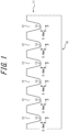
- FIG. 1 is a schematic diagram illustrating a position where residual compressive stress is specified in the present disclosure.
- a female thread portion 11 provided on the inner peripheral surface of at least one end of a steel pipe or tube 10 has a plurality of thread grooves 12.
- the bottom of each thread groove 12 is a thread bottom 13 of the female thread portion.
- the maximum value of residual compressive stress at a position P of 0.4 mm in the depth direction from each thread bottom 13 of the female thread portion is 100 MPa or more and less than or equal to the tensile strength of the material of the threaded steel pipe or tube.
- FIG. 1 is merely a schematic diagram for explanation, and does not represent the actual shape and dimensions of the thread portion.
- the tensile stress generated during use of the high pressure gas container spreads not only on the surface of the thread portion but also inside the material. Hence, the foregoing effect cannot be achieved if the residual compressive stress exists only in the surface layer of the thread portion. Accordingly, in the present disclosure, the maximum value of residual compressive stress at a position 0.4 mm in the depth direction from the thread bottom is 100 MPa or more.
- the maximum value of the residual compressive stress is excessively high, the threaded steel pipe or tube buckles and deforms.
- the maximum value of the residual compressive stress is less than or equal to the tensile strength of the material of the threaded steel pipe or tube.
- the maximum value of the residual compressive stress may be obtained by elasto-plastic analysis by the finite element method (FEM).
- FEM finite element method
- the maximum value of the residual compressive stress may be obtained by measuring the residual stress in a cross section of the female thread portion by X-ray stress measurement.
- the maximum value of the residual compressive stress is preferably less than or equal to the yield stress of the material of the threaded steel pipe or tube, from the viewpoint of more reliably preventing buckling of the thread portion.
- the material of the threaded steel pipe or tube is not limited, and may be any metal.
- the material is preferably low-alloy steel, from the viewpoint of cost reduction. It is particularly preferable to use, as the low-alloy steel, at least one of chromium molybdenum steel (JIS SCM steel), nickel chromium molybdenum steel (JIS SNCM steel), manganese chromium steel (JIS SMnC steel), manganese steel (JIS SMn steel), ASEM SA-723, and boron-added steel N28CB, N36CB, and N46CB.
- JIS SCM steel chromium molybdenum steel
- JIS SNCM steel nickel chromium molybdenum steel
- JIS SMnC steel manganese chromium steel
- ASEM SA-723 boron-added steel N28CB, N36CB, and N46CB.
- chromium molybdenum steel SA-723 steel, or nickel chromium molybdenum steel, with which quench hardenability can be easily ensured, is more preferable from the viewpoint of balancing with the material strength.
- chromium molybdenum steel (SCM435) contains C: 0.33 mass% to 0.38 mass%, Si: 0.15 mass% to 0.35 mass%, Mn: 0.60 mass% to 0.90 mass%, P: 0.030 mass% or less, S: 0.030 mass% or less, Cr: 0.90 mass% to 1.20 mass%, and Mo: 0.15 mass% to 0.30 mass%.
- any steel pipe or tube such as an electric resistance welded steel pipe or tube or a seamless steel pipe or tube may be used.
- a seamless steel pipe or tube is preferable.
- Seamless steel pipes or tubes not only have excellent properties such as toughness but also have no weld portions, and thus are very suitable for use in high pressure gas containers and the like.
- the depth of each thread groove is not limited.
- Di/Ds is preferably 0.8 or more, from the viewpoint of further reducing the stress exerted on the thread bottom.
- the inner diameter Ds of the female thread portion is defined as the distance between the thread bottoms at opposite positions of the female thread portion formed on the inner peripheral surface of the steel pipe or tube.
- the inner diameter Di of the raw pipe or tube refers to the inner diameter of the part of the steel pipe or tube where the female thread portion is not formed.
- threaded steel pipe or tube may be used for any purpose. Since the threaded steel pipe or tube has excellent fatigue strength in the thread portion as mentioned above, the threaded steel pipe or tube is particularly suitable for use in high pressure gas containers, joints (for example, joints for steel pipe or tube piles), and the like.
- a production method for a threaded steel pipe or tube in an embodiment of the present disclosure will be described below.
- stress is generated and local plastic deformation occurs in the thread bottom. Since plastic deformation occurs only in one part and most of the other regions are elastic regions, compressive stress remains in the thread bottom after the internal pressure or load is removed.
- the predetermined residual compressive stress can be applied to the female thread portion of the threaded steel pipe or tube.
- a threaded steel pipe or tube having the predetermined residual compressive stress can be produced by: attaching a lid having a male thread portion on the outer peripheral surface to a threaded steel pipe or tube having a female thread portion on the inner peripheral surface of at least one end (lid attachment process); and thereafter applying an internal pressure to the threaded steel pipe or tube with the lid attached thereto so as to satisfy specific conditions (internal pressure application process).
- a lid having a male thread portion on the outer peripheral surface is attached to a threaded steel pipe or tube having a female thread portion on the inner peripheral surface of at least one end so that the male thread portion will screw into the female thread portion (lid attachment process).
- FIG. 2 is a schematic diagram illustrating an example of a production method for a threaded steel pipe or tube 1 in this embodiment.
- the threaded steel pipe or tube 1 is composed of a cylindrical steel pipe or tube 10, and a female thread portion 11 is provided at at least one end of the steel pipe or tube 10.
- the female thread portion 11 is provided at both ends of the steel pipe or tube 10.
- a lid 40 having a male thread portion 41 on the outer peripheral surface is then attached to the threaded steel pipe or tube 1 so that the male thread portion 41 will screw into the female thread portion 11 of the threaded steel pipe or tube 1.
- the lid 40 preferably has an O-ring 42 as a sealing member on the outer peripheral surface.
- the male thread portion 41 is located on the container outer side of the O-ring 42 (i.e. on the side opposite to the internal space 14).
- any lid may be used as long as it can screw into the female thread portion of the threaded steel pipe or tube.
- the lid is attached to both ends of the threaded steel pipe or tube to enable internal pressure application.
- the lid can have a through-hole for taking in and out a pressure medium used in the below-described internal pressure application process.
- a pipe or a valve may be optionally connected to the through-hole.
- the material of the lid is not limited, but is preferably metal, and more preferably steel.
- a steel material having a tensile strength (TS) of 750 MPa or more is further preferable.
- the steel material may be, for example, low-alloy steel.
- the material of the lid may be the same as the foregoing material of the steel pipe or tube.
- the material of the lid and the material of the steel pipe or tube may be the same or different, but are preferably the same.
- an internal pressure is applied to the threaded steel pipe or tube with the lid attached thereto (internal pressure application process).
- the internal pressure needs to be applied under the following conditions (A), (B), and (C). The reasons for this will be given below.
- the thread bottom stress applied in the internal pressure application process is more than the tensile strength of the material.
- the thread bottom stress of the female thread portion is more than the tensile strength of the material of the threaded steel pipe or tube.
- the thread bottom stress of the female thread portion in the internal pressure application process is adjusted so as to apply the desired residual compressive stress.
- the stress on the outer surface of the threaded steel pipe or tube (the outer peripheral surface of the steel pipe or tube) facing the female thread portion is preferably less than or equal to the yield stress of the material of the threaded steel pipe or tube in the internal pressure application process.
- the residual compressive stress can be applied to the vicinity of the thread bottom more effectively than in the case where stress higher than the yield stress is applied to the threaded steel pipe or tube throughout its thickness.
- both the axial stress and the circumferential stress exerted on the threaded steel pipe or tube need to be less than or equal to the tensile strength of the material of the threaded steel pipe or tube.
- the axial stress and the circumferential stress exerted on the threaded steel pipe or tube can be calculated according to the following formulas (1) and (2) respectively:
- Axial stress pressure receiving area of lid ⁇ internal pressure / minimum cross ⁇ sectional area of threaded steel pipe or tube
- Circumferential stress inner diameter of threaded steel pipe or tube ⁇ internal pressure / 2 ⁇ thickness of threaded steel pipe or tube
- the "pressure-receiving area of lid” is the area of the inner surface (i.e. the surface receiving the internal pressure) of the lid.
- the "cross-sectional area of threaded steel pipe or tube” is the cross-sectional area of the steel part in a cross section perpendicular to the axial direction of the threaded steel pipe or tube, and does not include the cross-sectional area of the internal space of the steel pipe or tube.
- the cross-sectional area of the threaded steel pipe or tube may vary depending on the position in the longitudinal direction of the threaded steel pipe or tube, and the axial stress exerted on the threaded steel pipe or tube is maximum in the part where the cross-sectional area is minimum. Accordingly, the minimum cross-sectional area of the threaded steel pipe or tube is used in the formula (1).
- the axial stress and the circumferential stress exerted on the threaded steel pipe or tube are preferably less than or equal to the yield stress of the material of the threaded steel pipe or tube, and more preferably less than or equal to 90 % of the yield stress.
- the threaded steel pipe or tube is filled with any pressure medium.
- the pressure medium is not limited, and may be any medium.
- an incompressible fluid such as water or oil is preferable.
- an incompressible fluid containing a corrosion inhibitor or an aqueous solution of alcohol such as ethylene glycol is preferable.
- a threaded steel pipe or tube having the predetermined residual compressive stress can be produced by: attaching a jig having a male thread portion on the outer peripheral surface to a threaded steel pipe or tube having a female thread portion on the inner peripheral surface of at least one end (jig attachment process); and thereafter applying a load to the threaded steel pipe or tube using the jig so as to satisfy predetermined conditions (load application process). This will be described in detail below, with reference to FIG. 3 .
- FIG. 3 is a schematic diagram illustrating an example of a production method for a threaded steel pipe or tube 1 in this embodiment, i.e. a method that applies a load using a jig.
- the threaded steel pipe or tube 1 is composed of a cylindrical steel pipe or tube 10, and a female thread portion 11 is provided at at least one end of the steel pipe or tube 10.
- the female thread portion 11 is provided at both ends of the steel pipe or tube 10.
- a jig 20 having a male thread portion 21 on the outer peripheral surface is attached to the threaded steel pipe or tube 1 so that the male thread portion 21 will screw into the female thread portion 11 of the threaded steel pipe or tube 1 (jig attachment process).
- any jig having the male thread portion 21 that screws into the female thread portion 11 may be used.
- the material of the jig is not limited, but is preferably metal, and more preferably steel.
- a steel material having a tensile strength (TS) of 750 MPa or more is further preferable.
- the steel material may be, for example, low-alloy steel.
- the material of the jig may be the same as the foregoing material of the steel pipe or tube.
- the material of the jig and the material of the steel pipe or tube may be the same or different, but are preferably the same.
- a load is applied to the threaded steel pipe or tube 1 using the attached jig 20 (load application process).
- the method of applying the load is not limited.
- the load may be applied by pulling the jig 20 in the direction parallel to the axis of the threaded steel pipe or tube 1 and toward the outside of the pipe or tube (i.e. the direction of arrow A in FIG. 3 ) in a state in which the threaded steel pipe or tube 1 is fixed.
- a rod 22 attached to the jig 20 may be pulled by a load application device 30.
- the load is applied to the female thread portion 11 provided at one end of the threaded steel pipe or tube 1.
- the female thread portion 11 is provided at both ends of the threaded steel pipe or tube 1
- the application of the load to one female thread portion 11 and the application of the load to the other female thread portion 11 may be performed simultaneously or separately.
- the thread bottom stress applied in the load application process is more than the tensile strength of the material. In other words, it is preferable to apply the load under the following condition (A') in the load application process.
- the thread bottom stress of the female thread portion is more than the tensile strength of the material of the threaded steel pipe or tube.
- the thread bottom stress of the female thread portion in the load application process is adjusted so as to apply the desired residual compressive stress.
- the stress on the outer surface of the threaded steel pipe or tube (the outer peripheral surface of the steel pipe or tube) facing the female thread portion is preferably less than or equal to the yield stress of the material of the threaded steel pipe or tube in the load application process.
- the residual compressive stress can be applied to the vicinity of the thread bottom more effectively than in the case where stress higher than the yield stress is applied to the threaded steel pipe or tube throughout its thickness.
- the "cross-sectional area of threaded steel pipe or tube” is the cross-sectional area of the part where metal exists in a cross section perpendicular to the axial direction of the threaded steel pipe or tube.
- the cross-sectional area of the threaded steel pipe or tube may vary depending on the position in the longitudinal direction of the threaded steel pipe or tube, and the axial stress exerted on the threaded steel pipe or tube is maximum in the part where the cross-sectional area is minimum. Accordingly, the minimum cross-sectional area of the threaded steel pipe or tube is used in the formula (1).
- the axial stress exerted on the threaded steel pipe or tube is more than the yield stress of the material of the threaded steel pipe or tube, there is a possibility that the steel pipe or tube deforms plastically and the inner diameter of the steel pipe or tube changes. If the inner diameter changes, the sealability decreases when the threaded steel pipe or tube is used for a high pressure gas container or the like. Therefore, from the viewpoint of suppressing a decrease in sealability due to plastic deformation of the steel pipe or tube, the axial stress exerted on the threaded steel pipe or tube is preferably less than or equal to the yield stress of the material of the threaded steel pipe or tube, and more preferably less than or equal to 90 % of the yield stress. In other words, it is preferable to apply the load under the following condition (B') and more preferable to apply the load under the following condition (B") in the load application process.
- the axial stress of the threaded steel pipe or tube is less than or equal to the yield stress of the material of the threaded steel pipe or tube.
- the axial stress of the threaded steel pipe or tube is less than or equal to 90 % of the yield stress of the material of the threaded steel pipe or tube.
- the thread bottom stress was analyzed by elasto-plastic analysis by the finite element method (FEM) using models of threaded steel pipes or tubes. Assuming the use of threaded steel pipes or tubes as high pressure gas containers, the following two types of models were used: a Type 1 container composed of a threaded steel pipe or tube made of low-alloy steel as a metallic container and having no carbon fiber reinforced resin layer; and a Type 2 container composed of a threaded steel pipe or tube (liner) made of low-alloy steel same as the Type 1 container and a carbon fiber reinforced resin layer formed by winding CFRP on the surface of the threaded steel pipe or tube so as to have a thickness of 5 mm.
- FEM finite element method
- the threaded steel pipe or tube forming the metallic container and the lid used in the below-described internal pressure application process and performance evaluation were made of the same low-alloy steel.
- the tensile strength (TS) of the low-alloy steel was 821 MPa, and the yield stress (YP ) of the low-alloy steel was 705 MPa.
- As the stress-strain curve of the low-alloy steel the stress-strain curve of TS: 900 MPa class SNCM439 steel was used.
- the lid had a structure including a disk-shaped end plate and a hollow cylindrical screw nut.
- the thickness of the end plate was 75 mm
- the thickness of the screw nut was 37 mm.
- the thickness of the screw nut is the thickness from the apex of the thread portion provided on the outer peripheral surface to the inner surface.
- the screw shape was a JIS trapezoidal screw with a pitch of 12 mm, a thread depth of 12 mm, and a thread shoulder curvature radius of 2.2 mm.
- the thread bottom stress when the internal pressure shown in Table 1 was applied to the metallic container was obtained by FEM.
- the maximum value of the thread bottom stress in the female thread portion is shown in Table 1.
- the maximum value of the thread bottom stress refers to the maximum value of the stress throughout the thickness from the thread bottom to the surface on the side opposite to the thread bottom.
- the axial stress and the circumferential stress of the threaded steel pipe or tube when the internal pressure was applied are also shown in Table 1.
- the axial stress and the circumferential stress were calculated according to the following formulas (1) and (2):
- Axial stress pressure receiving area of lid ⁇ internal pressure / minimum cross ⁇ sectional area of threaded steel pipe or tube
- Circumferential stress inner diameter of threaded steel pipe or tube ⁇ internal pressure / 2 ⁇ thickness of threaded steel pipe or tube
- the axial stress and the circumferential stress were obtained by FEM analysis.
- the fracture life of the thread portion in the pressure cycle test was evaluated.
- the fracture life was evaluated according to the "Crack Growth Analysis Method for Various Sites" (KHKS 0220 (2010) Annex IX) stipulated by the High Pressure Gas Safety Institute of Japan.
- the pressure application conditions were as follows: minimum pressure: 2 MPa, maximum pressure: 82 MPa, and temperature: room temperature.
- Table 1 No. Metallic container Lid Internal pressure application conditions Container type Metallic cylinder Internal pressure (MPa) Maximum value of thread bottom stress of female thread portion (MPa) Axial stress (MPa) Circumferential stress (MPa) Thickness (mm) Outer diameter (mm) Inner diameter (mm) Minimum thickness of female thread portion (mm) Minimum cross-sectional area (mm 2 ) Pressure receiving area (mm 2 ) 1 Type1 30 404 344 18 21828 92941 111 1092 471 635 2 Type1 35 404 334 23 27530 87616 133 1080 422 633 3 Type1 40 404 324 28 33075 82448 157 1108 390 634 4 Type1 45 404 314 33 38463 77437 182 1080 366 634 5 Type1 45 404 314 33 38463 77437 50 365 101 174 6 Type1 50 404 304 38 43693 72583 2 23 3 6 7 Type1 50 404 304 38 43693 72583 25 281 42 76 8 Type1
- the thread bottom stress was analyzed by elasto-plastic analysis according to the same procedure as in Example 1 except that a load was applied using a jig instead of applying an internal pressure in a lidded state.
- a jig having the same shape as the lid used in Example 1 was used as the jig.
- the thread bottom stress when applying the load to the metallic container using the jig was obtained by FEM.
- the maximum value of the thread bottom stress in the female thread portion is shown in Table 3.
- the load was applied by moving (displacing) the jig in the direction parallel to the pipe or tube axis and toward the outside of the pipe or tube on calculation.
- the displacement of the jig was controlled so that the maximum value of the thread bottom stress would be the value shown in Table 3.
- the maximum value of the thread bottom stress refers to the maximum value of the stress throughout the thickness from the thread bottom to the surface on the side opposite to the thread bottom.
Landscapes
- Engineering & Computer Science (AREA)
- General Engineering & Computer Science (AREA)
- Mechanical Engineering (AREA)
- Pressure Vessels And Lids Thereof (AREA)
- Filling Or Discharging Of Gas Storage Vessels (AREA)
Abstract
Description
- The present disclosure relates to a threaded steel pipe or tube, and in particular to a threaded steel pipe or tube that has excellent fatigue strength in its thread portion and is suitable for use in high pressure gas containers and the like. The present disclosure also relates to a production method for the threaded steel pipe or tube.
- Fuel cell vehicles, which can solve not only the CO2 emission issue but also the energy issue, are expected as new vehicles in the future. Hydrogen stations for supplying hydrogen to fuel cell vehicles are equipped with high pressure gas containers (also referred to as pressure vessels) that store hydrogen at a pressure of 80 MPa or more.
- There are mainly two types of shapes of such high pressure gas containers: One is a cylinder-type container with a dome part formed by drawing an end of a pipe or tube, such as a gas cylinder. The other is a straight-type container with lids on both ends of a straight pipe or tube.
- The cylinder-type container has a shape in which the cross-sectional area inside the container decreases toward a gas outlet, i.e. a longitudinal end. The end is referred to as "dome part". A mouthpiece for taking gas in and out is provided at the tip of the dome part, and is sealed with a fastener having a screw. Since the area of the fastener is sufficiently small as compared with the cross-sectional area of the cylindrical part of the cylinder-type container, the stress exerted on the thread portion of the mouthpiece is reduced and therefore there is no problem with pressure sealing. However, high pressure gas containers for hydrogen stations and the like require periodic inner surface inspection after start of use, and it is difficult to perform inner surface inspection on the cylinder-type container.
- In the case of producing a high pressure gas container using a metallic container, the metallic container is usually subjected to heat treatment for the purpose of strength improvement. The heat treatment typically involves quenching, i.e. a process of heating the metallic container and then rapidly cooling it using a coolant. In the case of the cylinder-type container, however, charging and discharging the coolant into and from the container takes time, so that the cooling rate in the heat treatment decreases and the steel microstructure varies greatly.
- Moreover, while scale and a decarburized layer form on the surface of the metallic container due to the heat treatment, in the case of the cylinder-type container, it is difficult to remove such scale and decarburized layer formed on the container inner surface. Accordingly, the inner surface of the metallic container is used as heat treated, which causes degradation in the fatigue resistance of the metallic container.
- These problems may be avoided by using the straight-type container. In a structure in which a straight pipe or tube is lidded, the opening of the pipe or tube is large, so that cooling in the heat treatment is easy and the microstructure of the steel material can be precisely controlled. In addition, a decarburized layer and scale which form during the heat treatment can be easily removed by machining. Moreover, the inner surface of the container can be easily inspected after use by removing the lid. Furthermore, since the straight-type container does not have a dome part formed by deep drawing, there is little variation caused by processing, and uniform container production is possible. Examples of such high pressure gas containers include those described in
JP 2015-158243 A JP 2017-141919 A -
- PTL 1:
JP 2015-158243 A - PTL 2:
JP 2017-141919 A - In the case of using the straight-type container, all internal pressure is received by the lid because the cross section of the container is constant. The lid structure of the high pressure gas container using the straight-type container is thus required to withstand very high pressure.
- Examples of the lid structure of the straight-type container include a structure in which a flange is provided at an end of the straight-type container and the lid is bolted using the flange, and a structure in which a female thread portion is provided at an end of a steel pipe or tube and a lid having a male thread portion that screws into the female thread portion is screwed to the steel pipe or tube.
- However, the lid structure using the flange has the problem in that the provision of the flange causes an increase in container size and an increase in cost. To meet the demand for reduction in container size and cost, it is desirable to use the screw-type lid structure.
- With the screw-type lid structure, the problem in the case of using the flange can be avoided. However, high stress applied to the thread portion can cause fatigue fracture originating from the thread portion. For longer fatigue life of the high pressure gas container, it is necessary to prevent fatigue fracture originating from the thread portion of the threaded steel pipe or tube used as the container body.
- In the case of using the threaded steel pipe or tube for other than high pressure gas containers, too, it is desirable to prevent fatigue fracture originating from the thread portion in order to extend the product life.
- It could therefore be helpful to alleviate stress exerted on a thread portion of a threaded steel pipe or tube during use to prevent fatigue fracture.
- Upon examination, we discovered the following.
- (1) When a metallic container of a high pressure gas container is filled with gas, internal pressure is exerted on the metallic container, and causes tensile stress on the metallic container. The tensile stress is concentrated in the thread portion, especially near the thread bottom.
- (2) By applying specific residual compressive stress beforehand to the vicinity of the thread bottom of the threaded steel pipe or tube used as the metallic container, at least part of the tensile stress exerted on the thread portion when the metallic container is filled with gas is offset by the residual compressive stress, so that the stress actually exerted on the thread portion can be alleviated significantly. Fatigue fracture originating from the thread portion can thus be suppressed.
- (3) In the case of using the threaded steel pipe or tube for other than metallic containers, too, by applying the predetermined residual compressive stress to the vicinity of the thread bottom beforehand, the stress exerted on the thread portion during use can be alleviated to thus suppress fatigue fracture.
- (4) When internal pressure is applied to the threaded steel pipe or tube in a state in which a lid having a male thread portion that screws into the female thread portion of the threaded steel pipe or tube is attached thereto, stress is generated and local plastic deformation occurs in the thread bottom. Since plastic deformation occurs only in one part and most of the other regions are elastic regions, compressive stress remains in the thread bottom after the internal pressure is removed. Hence, by applying an appropriate load to the threaded steel pipe or tube in a state in which the lid is attached thereto, the predetermined residual compressive stress can be applied to the female thread portion of the threaded steel pipe or tube.
- (5) Likewise, by applying the load to the threaded steel pipe or tube using a jig having a male thread portion that screws into the female thread portion of the threaded steel pipe or tube, the predetermined residual compressive stress can be applied to the female thread portion of the threaded steel pipe or tube.
- The present disclosure is based on these discoveries. We thus provide the following.
- 1. A threaded steel pipe or tube having a female thread portion on an inner peripheral surface of at least one end, wherein a maximum value of residual compressive stress at a position of 0.4 mm in a depth direction from a thread bottom of the female thread portion is 100 MPa or more and less than or equal to tensile strength of a material of the threaded steel pipe or tube.
- 2. The threaded steel pipe or tube according to 1., wherein the maximum value of the residual compressive stress is less than or equal to yield stress of the material of the threaded steel pipe or tube.
- 3. The threaded steel pipe or tube according to 1. or 2., comprising a seamless steel pipe or tube.
- 4. A production method for a threaded steel pipe or tube, the production method comprising: attaching a lid having a male thread portion on an outer peripheral surface to a threaded steel pipe or tube having a female thread portion on an inner peripheral surface of at least one end so that the male thread portion is screwed into the female thread portion; and applying an internal pressure to the threaded steel pipe or tube with the lid attached thereto, under the following conditions (A), (B), and (C):
- (A) thread bottom stress of the female thread portion is more than yield stress of a material of the threaded steel pipe or tube;
- (B) axial stress of the threaded steel pipe or tube is less than or equal to tensile strength of the material of the threaded steel pipe or tube; and
- (C) circumferential stress of the threaded steel pipe or tube is less than or equal to the tensile strength of the material of the threaded steel pipe or tube.
- 5. A production method for a threaded steel pipe or tube, the production method comprising: attaching a jig having a male thread portion on an outer peripheral surface to a threaded steel pipe or tube having a female thread portion on an inner peripheral surface of at least one end so that the male thread portion is screwed into the female thread portion; and applying a load to the threaded steel pipe or tube using the jig, under the following conditions (A) and (B):
- (A) thread bottom stress of the female thread portion is more than yield stress of a material of the threaded steel pipe or tube; and
- (B) axial stress of the threaded steel pipe or tube is less than or equal to tensile strength of the material of the threaded steel pipe or tube.
- 6. The production method for a threaded steel pipe or tube according to 4. or 5., wherein the threaded steel pipe or tube comprises a seamless steel pipe or tube.
- It is thus possible to alleviate stress exerted on a thread portion of a threaded steel pipe or tube during use to prevent fatigue fracture. Such a threaded steel pipe or tube can be used with higher pressure and larger cross section than conventional threaded steel pipe or tubes.
- In the accompanying drawings:
-
FIG. 1 is a schematic diagram illustrating a position where residual compressive stress is specified in the present disclosure; -
FIG. 2 is a schematic diagram illustrating an example of a production method for a threaded steel pipe or tube in Embodiment 1; and -
FIG. 3 is a schematic diagram illustrating an example of a production method for a threaded steel pipe or tube in Embodiment 2. - The following will describe embodiments of the present disclosure in detail. The following description shows examples of preferred embodiments of the present disclosure and does not limit the scope of the present disclosure.
- A threaded steel pipe or tube in an embodiment of the present disclosure has a female thread portion on the inner peripheral surface of at least one end. When using the threaded steel pipe or tube, a member having a male thread portion corresponding to the female thread portion can be screwed into the threaded steel pipe or tube. For example, in the case of using the threaded steel pipe or tube as a high pressure gas container, a screw-type lid having a male thread portion can be attached to the female thread portion.
- The threaded steel pipe or tube may have the female thread portion on the inner peripheral surface of only one end, or on the inner peripheral surface of both ends. In the case where the threaded steel pipe or tube has the female thread portion on the inner peripheral surface of only one end, the threaded steel pipe or tube may have a male thread portion on the inner peripheral surface of the other end.
- In the present disclosure, it is important that the maximum value of residual compressive stress at a position of 0.4 mm in the depth direction from the thread bottom of the female thread portion is 100 MPa or more and less than or equal to the tensile strength of the material of the threaded steel pipe or tube. The reasons for this will be given below.
-
FIG. 1 is a schematic diagram illustrating a position where residual compressive stress is specified in the present disclosure. Afemale thread portion 11 provided on the inner peripheral surface of at least one end of a steel pipe ortube 10 has a plurality ofthread grooves 12. The bottom of eachthread groove 12 is athread bottom 13 of the female thread portion. In the present disclosure, the maximum value of residual compressive stress at a position P of 0.4 mm in the depth direction from eachthread bottom 13 of the female thread portion is 100 MPa or more and less than or equal to the tensile strength of the material of the threaded steel pipe or tube.FIG. 1 is merely a schematic diagram for explanation, and does not represent the actual shape and dimensions of the thread portion. - As mentioned above, when a metallic container of a high pressure gas container is filled with gas during use, internal pressure is exerted on the metallic container and causes tensile stress. The tensile stress is concentrated in the thread portion, especially near the thread bottom. By applying residual compressive stress beforehand to the vicinity of the thread bottom of the threaded steel pipe or tube, at least part of the tensile stress exerted on the thread portion when the metallic container is filled with gas is offset by the residual compressive stress, so that the stress actually exerted on the thread portion can be alleviated significantly. Fatigue fracture originating from the thread portion can thus be suppressed.
- Here, the tensile stress generated during use of the high pressure gas container spreads not only on the surface of the thread portion but also inside the material. Hence, the foregoing effect cannot be achieved if the residual compressive stress exists only in the surface layer of the thread portion. Accordingly, in the present disclosure, the maximum value of residual compressive stress at a position 0.4 mm in the depth direction from the thread bottom is 100 MPa or more.
- Meanwhile, if the maximum value of the residual compressive stress is excessively high, the threaded steel pipe or tube buckles and deforms. To prevent deformation of the threaded steel pipe or tube, the maximum value of the residual compressive stress is less than or equal to the tensile strength of the material of the threaded steel pipe or tube.
- The maximum value of the residual compressive stress may be obtained by elasto-plastic analysis by the finite element method (FEM). Alternatively, the maximum value of the residual compressive stress may be obtained by measuring the residual stress in a cross section of the female thread portion by X-ray stress measurement.
- The maximum value of the residual compressive stress is preferably less than or equal to the yield stress of the material of the threaded steel pipe or tube, from the viewpoint of more reliably preventing buckling of the thread portion.
- The material of the threaded steel pipe or tube is not limited, and may be any metal. The material is preferably low-alloy steel, from the viewpoint of cost reduction. It is particularly preferable to use, as the low-alloy steel, at least one of chromium molybdenum steel (JIS SCM steel), nickel chromium molybdenum steel (JIS SNCM steel), manganese chromium steel (JIS SMnC steel), manganese steel (JIS SMn steel), ASEM SA-723, and boron-added steel N28CB, N36CB, and N46CB. Of these, chromium molybdenum steel, SA-723 steel, or nickel chromium molybdenum steel, with which quench hardenability can be easily ensured, is more preferable from the viewpoint of balancing with the material strength. For example, chromium molybdenum steel (SCM435) contains C: 0.33 mass% to 0.38 mass%, Si: 0.15 mass% to 0.35 mass%, Mn: 0.60 mass% to 0.90 mass%, P: 0.030 mass% or less, S: 0.030 mass% or less, Cr: 0.90 mass% to 1.20 mass%, and Mo: 0.15 mass% to 0.30 mass%.
- As the steel pipe or tube, any steel pipe or tube such as an electric resistance welded steel pipe or tube or a seamless steel pipe or tube may be used. In particular, a seamless steel pipe or tube is preferable. Seamless steel pipes or tubes not only have excellent properties such as toughness but also have no weld portions, and thus are very suitable for use in high pressure gas containers and the like.
- In the present disclosure, the depth of each thread groove is not limited. However, if the ratio of the inner diameter Di of the raw pipe or tube to the inner diameter Ds of the female thread portion, Di/Ds, is less than 0.8, the threads are excessively deep for the thickness of the steel pipe or tube (hollow piece), so that the stress exerted on the thread bottom increases. Therefore, Di/Ds is preferably 0.8 or more, from the viewpoint of further reducing the stress exerted on the thread bottom. Herein, the inner diameter Ds of the female thread portion is defined as the distance between the thread bottoms at opposite positions of the female thread portion formed on the inner peripheral surface of the steel pipe or tube. The inner diameter Di of the raw pipe or tube refers to the inner diameter of the part of the steel pipe or tube where the female thread portion is not formed.
- The use of the threaded steel pipe or tube according to the present disclosure is not limited, and the threaded steel pipe or tube may be used for any purpose. Since the threaded steel pipe or tube has excellent fatigue strength in the thread portion as mentioned above, the threaded steel pipe or tube is particularly suitable for use in high pressure gas containers, joints (for example, joints for steel pipe or tube piles), and the like.
- A production method for a threaded steel pipe or tube in an embodiment of the present disclosure will be described below. As mentioned above, when internal pressure or load is applied to a threaded steel pipe or tube, stress is generated and local plastic deformation occurs in the thread bottom. Since plastic deformation occurs only in one part and most of the other regions are elastic regions, compressive stress remains in the thread bottom after the internal pressure or load is removed. Hence, by applying an appropriate internal pressure or load to the threaded steel pipe or tube, the predetermined residual compressive stress can be applied to the female thread portion of the threaded steel pipe or tube. The following will describe each of a production method by internal pressure application and a production method by load application in detail.
- In one embodiment of the present disclosure, a threaded steel pipe or tube having the predetermined residual compressive stress can be produced by: attaching a lid having a male thread portion on the outer peripheral surface to a threaded steel pipe or tube having a female thread portion on the inner peripheral surface of at least one end (lid attachment process); and thereafter applying an internal pressure to the threaded steel pipe or tube with the lid attached thereto so as to satisfy specific conditions (internal pressure application process).
- First, a lid having a male thread portion on the outer peripheral surface is attached to a threaded steel pipe or tube having a female thread portion on the inner peripheral surface of at least one end so that the male thread portion will screw into the female thread portion (lid attachment process).
-
FIG. 2 is a schematic diagram illustrating an example of a production method for a threaded steel pipe or tube 1 in this embodiment. The threaded steel pipe or tube 1 is composed of a cylindrical steel pipe ortube 10, and afemale thread portion 11 is provided at at least one end of the steel pipe ortube 10. In the example illustrated inFIG. 2 , thefemale thread portion 11 is provided at both ends of the steel pipe ortube 10. - A
lid 40 having amale thread portion 41 on the outer peripheral surface is then attached to the threaded steel pipe or tube 1 so that themale thread portion 41 will screw into thefemale thread portion 11 of the threaded steel pipe or tube 1. As illustrated inFIG. 2 , thelid 40 preferably has an O-ring 42 as a sealing member on the outer peripheral surface. Themale thread portion 41 is located on the container outer side of the O-ring 42 (i.e. on the side opposite to the internal space 14). - As the lid, any lid may be used as long as it can screw into the female thread portion of the threaded steel pipe or tube. In the case where the threaded steel pipe or tube has the female thread portion at both ends, the lid is attached to both ends of the threaded steel pipe or tube to enable internal pressure application.
- The lid can have a through-hole for taking in and out a pressure medium used in the below-described internal pressure application process. A pipe or a valve may be optionally connected to the through-hole.
- The material of the lid is not limited, but is preferably metal, and more preferably steel. As the steel, a steel material having a tensile strength (TS) of 750 MPa or more is further preferable. The steel material may be, for example, low-alloy steel. The material of the lid may be the same as the foregoing material of the steel pipe or tube. The material of the lid and the material of the steel pipe or tube may be the same or different, but are preferably the same.
- Next, an internal pressure is applied to the threaded steel pipe or tube with the lid attached thereto (internal pressure application process). In the internal pressure application process, the internal pressure needs to be applied under the following conditions (A), (B), and (C). The reasons for this will be given below.
- (A) The thread bottom stress of the female thread portion is more than the yield stress of the material of the threaded steel pipe or tube.
- (B) The axial stress of the threaded steel pipe or tube is less than or equal to the tensile strength of the material of the threaded steel pipe or tube.
- (C) The circumferential stress of the threaded steel pipe or tube is less than or equal to the tensile strength of the material of the threaded steel pipe or tube.
- To apply residual compressive stress to the vicinity of the thread bottom, it is necessary to cause plastic deformation in the thread bottom. Plastic deformation in the thread bottom can be caused by applying thread bottom stress exceeding the yield stress of the material. Therefore, in the present disclosure, the internal pressure is applied under the condition (A) in the internal pressure application process. As a result of the condition (A) being satisfied, residual compressive stress can be applied to the female thread portion.
- To apply the residual compressive stress more effectively, it is preferable that the thread bottom stress applied in the internal pressure application process is more than the tensile strength of the material. In other words, it is preferable to apply the internal pressure under the following condition (A') in the internal pressure application process.
- (A') The thread bottom stress of the female thread portion is more than the tensile strength of the material of the threaded steel pipe or tube.
- No upper limit is placed on the thread bottom stress of the female thread portion in the internal pressure application process, and the thread bottom stress is adjusted so as to apply the desired residual compressive stress. From the viewpoint of effectively applying the residual compressive stress, the stress on the outer surface of the threaded steel pipe or tube (the outer peripheral surface of the steel pipe or tube) facing the female thread portion is preferably less than or equal to the yield stress of the material of the threaded steel pipe or tube in the internal pressure application process. By limiting the thread bottom stress to more than the yield stress and at the same time limiting the stress on the outer surface of the threaded steel pipe or tube to less than or equal to the yield stress, the residual compressive stress can be applied to the vicinity of the thread bottom more effectively than in the case where stress higher than the yield stress is applied to the threaded steel pipe or tube throughout its thickness.
- As mentioned above, an internal pressure needs to be applied to cause plastic deformation, in order to apply residual compressive stress. If the internal pressure is excessive, however, the steel pipe or tube fractures. To prevent the fracture of the steel pipe or tube, both the axial stress and the circumferential stress exerted on the threaded steel pipe or tube need to be less than or equal to the tensile strength of the material of the threaded steel pipe or tube. These conditions are specifically defined in the foregoing (B) and (C).
- The axial stress and the circumferential stress exerted on the threaded steel pipe or tube can be calculated according to the following formulas (1) and (2) respectively:


- Herein, the "pressure-receiving area of lid" is the area of the inner surface (i.e. the surface receiving the internal pressure) of the lid. The "cross-sectional area of threaded steel pipe or tube" is the cross-sectional area of the steel part in a cross section perpendicular to the axial direction of the threaded steel pipe or tube, and does not include the cross-sectional area of the internal space of the steel pipe or tube. The cross-sectional area of the threaded steel pipe or tube may vary depending on the position in the longitudinal direction of the threaded steel pipe or tube, and the axial stress exerted on the threaded steel pipe or tube is maximum in the part where the cross-sectional area is minimum. Accordingly, the minimum cross-sectional area of the threaded steel pipe or tube is used in the formula (1).
- If at least one of the axial stress and the circumferential stress exerted on the threaded steel pipe or tube is more than the yield stress of the material of the threaded steel pipe or tube, there is a possibility that the steel pipe or tube deforms plastically and the inner diameter of the steel pipe or tube changes. If the inner diameter changes, the sealability decreases when the threaded steel pipe or tube is used for a high pressure gas container or the like. Therefore, from the viewpoint of suppressing a decrease in sealability due to plastic deformation of the steel pipe or tube, the axial stress and the circumferential stress exerted on the threaded steel pipe or tube are preferably less than or equal to the yield stress of the material of the threaded steel pipe or tube, and more preferably less than or equal to 90 % of the yield stress. In other words, it is preferable to apply the internal pressure under the following conditions (B') and (C') and more preferable to apply the internal pressure under the following conditions (B") and (C") in the internal pressure application process.
- (B') The axial stress of the threaded steel pipe or tube is less than or equal to the yield stress of the material of the threaded steel pipe or tube.
- (C') The circumferential stress of the threaded steel pipe or tube is less than or equal to the yield stress of the material of the threaded steel pipe or tube.
- (B") The axial stress of the threaded steel pipe or tube is less than or equal to 90 % of the yield stress of the material of the threaded steel pipe or tube.
- (C") The circumferential stress of the threaded steel pipe or tube is less than or equal to 90 % of the yield stress of the material of the threaded steel pipe or tube.
- To apply the internal pressure to the threaded steel pipe or tube in the internal pressure application process, the threaded steel pipe or tube is filled with any pressure medium. The pressure medium is not limited, and may be any medium. From the viewpoint of safety, an incompressible fluid such as water or oil is preferable. From the viewpoint of preventing corrosion of the threaded steel pipe or tube, an incompressible fluid containing a corrosion inhibitor or an aqueous solution of alcohol such as ethylene glycol is preferable.
- In another embodiment of the present disclosure, a threaded steel pipe or tube having the predetermined residual compressive stress can be produced by: attaching a jig having a male thread portion on the outer peripheral surface to a threaded steel pipe or tube having a female thread portion on the inner peripheral surface of at least one end (jig attachment process); and thereafter applying a load to the threaded steel pipe or tube using the jig so as to satisfy predetermined conditions (load application process). This will be described in detail below, with reference to
FIG. 3 . -
FIG. 3 is a schematic diagram illustrating an example of a production method for a threaded steel pipe or tube 1 in this embodiment, i.e. a method that applies a load using a jig. The threaded steel pipe or tube 1 is composed of a cylindrical steel pipe ortube 10, and afemale thread portion 11 is provided at at least one end of the steel pipe ortube 10. In the example illustrated inFIG. 3 , thefemale thread portion 11 is provided at both ends of the steel pipe ortube 10. - First, a
jig 20 having amale thread portion 21 on the outer peripheral surface is attached to the threaded steel pipe or tube 1 so that themale thread portion 21 will screw into thefemale thread portion 11 of the threaded steel pipe or tube 1 (jig attachment process). As thejig 20, any jig having themale thread portion 21 that screws into thefemale thread portion 11 may be used. - The material of the jig is not limited, but is preferably metal, and more preferably steel. As the steel, a steel material having a tensile strength (TS) of 750 MPa or more is further preferable. The steel material may be, for example, low-alloy steel. The material of the jig may be the same as the foregoing material of the steel pipe or tube. The material of the jig and the material of the steel pipe or tube may be the same or different, but are preferably the same.
- Next, a load is applied to the threaded steel pipe or tube 1 using the attached jig 20 (load application process). The method of applying the load is not limited. For example, the load may be applied by pulling the
jig 20 in the direction parallel to the axis of the threaded steel pipe or tube 1 and toward the outside of the pipe or tube (i.e. the direction of arrow A inFIG. 3 ) in a state in which the threaded steel pipe or tube 1 is fixed. Specifically, for example, arod 22 attached to thejig 20 may be pulled by aload application device 30. - In the example illustrated in
FIG. 3 , the load is applied to thefemale thread portion 11 provided at one end of the threaded steel pipe or tube 1. In the case where thefemale thread portion 11 is provided at both ends of the threaded steel pipe or tube 1, it is preferable to apply the load to each of thefemale thread portions 11 at both ends. In this case, the application of the load to onefemale thread portion 11 and the application of the load to the otherfemale thread portion 11 may be performed simultaneously or separately. - In the load application process, the load needs to be applied under the following conditions (A) and (B). The reasons for this will be given below.
- (A) The thread bottom stress of the female thread portion is more than the yield stress of the material of the threaded steel pipe or tube.
- (B) The axial stress of the threaded steel pipe or tube is less than or equal to the tensile strength of the material of the threaded steel pipe or tube.
- To apply residual compressive stress to the vicinity of the thread bottom, it is necessary to cause plastic deformation in the thread bottom. Plastic deformation in the thread bottom can be caused by applying thread bottom stress exceeding the yield stress of the material. Therefore, in the present disclosure, the load is applied under the condition (A) in the load application process. As a result of the condition (A) being satisfied, residual compressive stress can be applied to the female thread portion.
- To apply the residual compressive stress more effectively, it is preferable that the thread bottom stress applied in the load application process is more than the tensile strength of the material. In other words, it is preferable to apply the load under the following condition (A') in the load application process.
- (A') The thread bottom stress of the female thread portion is more than the tensile strength of the material of the threaded steel pipe or tube.
- No upper limit is placed on the thread bottom stress of the female thread portion in the load application process, and the thread bottom stress is adjusted so as to apply the desired residual compressive stress. From the viewpoint of effectively applying the residual compressive stress, the stress on the outer surface of the threaded steel pipe or tube (the outer peripheral surface of the steel pipe or tube) facing the female thread portion is preferably less than or equal to the yield stress of the material of the threaded steel pipe or tube in the load application process. By limiting the thread bottom stress to more than the yield stress and at the same time limiting the stress on the outer surface of the threaded steel pipe or tube to less than or equal to the yield stress, the residual compressive stress can be applied to the vicinity of the thread bottom more effectively than in the case where stress higher than the yield stress is applied to the threaded steel pipe or tube throughout its thickness.
- As mentioned above, a load needs to be applied to cause plastic deformation, in order to apply residual compressive stress. If the load is excessive, however, the steel pipe or tube fractures. To prevent the fracture of the steel pipe or tube, the axial stress exerted on the threaded steel pipe or tube needs to be less than or equal to the tensile strength of the material of the threaded steel pipe or tube. This condition is specifically defined in the foregoing (B).
- The axial stress exerted on the threaded steel pipe or tube can be calculated according to the following formula (1):

- Herein, the "cross-sectional area of threaded steel pipe or tube" is the cross-sectional area of the part where metal exists in a cross section perpendicular to the axial direction of the threaded steel pipe or tube. The cross-sectional area of the threaded steel pipe or tube may vary depending on the position in the longitudinal direction of the threaded steel pipe or tube, and the axial stress exerted on the threaded steel pipe or tube is maximum in the part where the cross-sectional area is minimum. Accordingly, the minimum cross-sectional area of the threaded steel pipe or tube is used in the formula (1).
- If the axial stress exerted on the threaded steel pipe or tube is more than the yield stress of the material of the threaded steel pipe or tube, there is a possibility that the steel pipe or tube deforms plastically and the inner diameter of the steel pipe or tube changes. If the inner diameter changes, the sealability decreases when the threaded steel pipe or tube is used for a high pressure gas container or the like. Therefore, from the viewpoint of suppressing a decrease in sealability due to plastic deformation of the steel pipe or tube, the axial stress exerted on the threaded steel pipe or tube is preferably less than or equal to the yield stress of the material of the threaded steel pipe or tube, and more preferably less than or equal to 90 % of the yield stress. In other words, it is preferable to apply the load under the following condition (B') and more preferable to apply the load under the following condition (B") in the load application process.
- (B') The axial stress of the threaded steel pipe or tube is less than or equal to the yield stress of the material of the threaded steel pipe or tube.
- (B") The axial stress of the threaded steel pipe or tube is less than or equal to 90 % of the yield stress of the material of the threaded steel pipe or tube.
- The effects according to the present disclosure will be described below by way of examples. The present disclosure is not limited to the examples described below.
- The thread bottom stress was analyzed by elasto-plastic analysis by the finite element method (FEM) using models of threaded steel pipes or tubes. Assuming the use of threaded steel pipes or tubes as high pressure gas containers, the following two types of models were used: a Type 1 container composed of a threaded steel pipe or tube made of low-alloy steel as a metallic container and having no carbon fiber reinforced resin layer; and a Type 2 container composed of a threaded steel pipe or tube (liner) made of low-alloy steel same as the Type 1 container and a carbon fiber reinforced resin layer formed by winding CFRP on the surface of the threaded steel pipe or tube so as to have a thickness of 5 mm. The threaded steel pipe or tube forming the metallic container and the lid used in the below-described internal pressure application process and performance evaluation were made of the same low-alloy steel. The tensile strength (TS) of the low-alloy steel was 821 MPa, and the yield stress (YP ) of the low-alloy steel was 705 MPa. As the stress-strain curve of the low-alloy steel, the stress-strain curve of TS: 900 MPa class SNCM439 steel was used.
- Regarding the dimensions of the threaded steel pipe or tube forming the metallic container, the length in the longitudinal direction was fixed at 4500 mm, the outer diameter was fixed at 404 mm, and the inner diameter and the thickness were as shown in Table 1. The lid had a structure including a disk-shaped end plate and a hollow cylindrical screw nut. The thickness of the end plate was 75 mm, and the thickness of the screw nut was 37 mm. Herein, the thickness of the screw nut is the thickness from the apex of the thread portion provided on the outer peripheral surface to the inner surface. The screw shape was a JIS trapezoidal screw with a pitch of 12 mm, a thread depth of 12 mm, and a thread shoulder curvature radius of 2.2 mm.
- FEM analysis was performed with the following conditions:
- Software: ABAQUS Ver. 6.12-4 (Dassault Systèmes).
- Calculation model: axisymmetric model.
- Mesh division: 50 µm in stress concentration part.
- Boundary condition: gas pressure applied to the inner surface of the threaded steel pipe or tube and the gas storage side of the end plate.
- Constraint condition: metallic cylinder: node on Y symmetry plane, Y direction displacement constraint.
- End plate, screw nut: no positive node displacement fixation.
- Contact condition: contact friction coefficient µ = 0.05.
- The thread bottom stress when the internal pressure shown in Table 1 was applied to the metallic container was obtained by FEM. The maximum value of the thread bottom stress in the female thread portion is shown in Table 1. The maximum value of the thread bottom stress refers to the maximum value of the stress throughout the thickness from the thread bottom to the surface on the side opposite to the thread bottom.
- The axial stress and the circumferential stress of the threaded steel pipe or tube when the internal pressure was applied are also shown in Table 1. In the case where the metallic container was the Type 1 container, the axial stress and the circumferential stress were calculated according to the following formulas (1) and (2):


- In the case where the metallic container was the Type 2 container, the axial stress and the circumferential stress were obtained by FEM analysis.
- Next, the residual compressive stress at a position 0.4 mm in the depth direction from the thread bottom of the female thread portion in a state in which the internal pressure was removed was obtained by FEM analysis. The maximum value of the residual compressive stress is shown in Table 2.
- Next, to evaluate the performance of each threaded steel pipe or tube, the thread bottom stress when applying the internal pressure again and the thread portion fracture life were obtained.
- Assuming the conditions when actually using the threaded steel pipe or tube as a high pressure gas container, the maximum value of the thread bottom stress when applying an internal pressure of 82 MPa to the threaded steel pipe or tube with the lid attached thereto was obtained by FEM analysis. The results are shown in Table 2.
- From the stress obtained by FEM analysis, the fracture life of the thread portion in the pressure cycle test was evaluated. The fracture life was evaluated according to the "Crack Growth Analysis Method for Various Sites" (KHKS 0220 (2010) Annex IX) stipulated by the High Pressure Gas Safety Institute of Japan. The pressure application conditions were as follows: minimum pressure: 2 MPa, maximum pressure: 82 MPa, and temperature: room temperature.
- As can be understood from the results shown in Table 2, by applying internal pressure under appropriate conditions, residual compressive stress satisfying the conditions according to the present disclosure was able to be introduced into the thread bottom. In each threaded steel pipe or tube in which the maximum value of residual compressive stress at a position of 0.4 mm in the depth direction from the thread bottom satisfied the conditions according to the present disclosure, the thread bottom stress when the internal pressure was applied was reduced, and consequently excellent fatigue life was achieved.
-
Table 1 No. Metallic container Lid Internal pressure application conditions Container type Metallic cylinder Internal pressure (MPa) Maximum value of thread bottom stress of female thread portion (MPa) Axial stress (MPa) Circumferential stress (MPa) Thickness (mm) Outer diameter (mm) Inner diameter (mm) Minimum thickness of female thread portion (mm) Minimum cross-sectional area (mm2) Pressure receiving area (mm2) 1 Type1 30 404 344 18 21828 92941 111 1092 471 635 2 Type1 35 404 334 23 27530 87616 133 1080 422 633 3 Type1 40 404 324 28 33075 82448 157 1108 390 634 4 Type1 45 404 314 33 38463 77437 182 1080 366 634 5 Type1 45 404 314 33 38463 77437 50 365 101 174 6 Type1 50 404 304 38 43693 72583 2 23 3 6 7 Type1 50 404 304 38 43693 72583 25 281 42 76 8 Type1 50 404 304 38 43693 72583 50 563 83 152 9 Type1 50 404 304 38 43693 72583 60 675 100 182 10 Type1 50 404 304 38 43693 72583 63 690 105 192 11 Type1 50 404 304 38 43693 72583 70 788 116 213 12 Type1 50 404 304 38 43693 72583 209 1100 347 635 13 Type2 55 404 294 43 48767 67887 300 1180 418 650 14 Type2 55 404 294 43 48767 67887 380 1280 529 710 15 Type1 55 404 294 43 48767 67887 237 1080 330 634 16 Type1 55 404 294 43 48767 67887 50 309 70 134 17 Type1 60 404 284 48 53684 63347 268 1092 316 635 18 Type1 60 404 284 48 53684 63347 50 292 59 118 19 Type1 65 404 274 53 58443 58965 301 1102 303 634 20 Type1 70 404 264 58 63045 54739 337 1108 292 635 21 Type1 50 450 350 38 49185 96211 180 1132 352 630 22 Type1 50 425 325 38 46200 82958 190 1050 341 618 23 Type1 50 350 250 38 37247 49087 240 1020 316 600 24 Type1 50 250 150 38 25309 17671 350 850 244 525 25 Type1 80 350 190 68 60243 28353 480 756 226 570 -
Table 2 No. Maximum value of residual compressive stress at position of 0.4mm in depth direction from thread bottom of female thread portion (MPa) Test results Remarks Maximum value of thread bottom stress when applying internal pressure of 82MPa (MPa) Thread portion fracture life (times) 1 435 698 256778 Example 2 401 630 313321 Example 3 346 572 296674 Example 4 331 514 324351 Example 5 0 803 126690 Comparative Example 6 0 793 130456 Comparative Example 7 0 793 130069 Comparative Example 8 0 793 138892 Comparative Example 9 15 793 131232 Comparative Example 10 53 700 150789 Comparative Example 11 105 682 266045 Example 12 345 456 623345 Example 13 468 380 789654 Example 14 780 310 1132014 Example 15 332 419 753212 Example 16 0 781 152496 Comparative Example 17 112 391 546672 Example 18 0 757 242496 Comparative Example 19 265 370 599012 Example 20 280 351 755431 Example 21 320 502 312355 Example 22 340 525 304456 Example 23 115 695 243318 Example 24 230 325 1099540 Example 25 215 280 1344351 Example - The thread bottom stress was analyzed by elasto-plastic analysis according to the same procedure as in Example 1 except that a load was applied using a jig instead of applying an internal pressure in a lidded state. In this example, a jig having the same shape as the lid used in Example 1 was used as the jig.
- The thread bottom stress when applying the load to the metallic container using the jig was obtained by FEM. The maximum value of the thread bottom stress in the female thread portion is shown in Table 3. The load was applied by moving (displacing) the jig in the direction parallel to the pipe or tube axis and toward the outside of the pipe or tube on calculation. Here, the displacement of the jig was controlled so that the maximum value of the thread bottom stress would be the value shown in Table 3. The maximum value of the thread bottom stress refers to the maximum value of the stress throughout the thickness from the thread bottom to the surface on the side opposite to the thread bottom.
- The following values were then evaluated according to the same procedures as in Example 1. The evaluation results are shown in Table 4.
- Residual compressive stress at a position of 0.4 mm in the depth direction from the thread bottom of the female thread portion with the load removed.
- Maximum value of thread bottom stress when applying an internal pressure of 82 MPa.
- Fracture life of thread portion in pressure cycle test.
- As can be understood from the results shown in Table 4, by applying a load using a jig under appropriate conditions, residual compressive stress satisfying the conditions according to the present disclosure was able to be introduced into the thread bottom. In each threaded steel pipe or tube in which the maximum value of the residual compressive stress at a position of 0.4 mm in the depth direction from the thread bottom satisfied the conditions according to the present disclosure, the thread bottom stress when the internal pressure was applied was reduced, and excellent fatigue life was achieved.
-
Table 3 No. Metallic container Load application conditions Container type Metallic cylinder Maximum value of thread bottom stress of female thread portion (MPa) Axial stress (MPa) Thickness (mm) Outer diameter (mm) Inner diameter (mm) Minimum thickness of female thread portion (mm) Minimum cross-sectional area (mm2) 26 Type 1 30 404 344 18 21828 1100 475 27 Type 1 35 404 334 23 27530 1100 440 28 Type 1 40 404 324 28 33075 1100 390 29 Type 1 45 404 314 33 38463 1100 366 30 Type 1 45 404 314 33 38463 350 80 31 Type1 50 404 304 38 43693 350 65 -
Table 4 No. Maximum value of residual compressive stress at position of 0.4mm in depth direction from thread bottom of female thread portion (MPa) Test results Remarks Maximum value of thread bottom stress when applying internal pressure of 82MPa (MPa) Thread portion fracture life (times) 26 440 702 245978 Example 27 421 610 333321 Example 28 346 572 296674 Example 29 346 498 348351 Example 30 0 793 116640 Comparative Example 31 0 700 130456 Comparative Example -
- 1
- threaded steel pipe or tube
- 10
- steel pipe or tube
- 11
- female thread portion
- 12
- thread groove
- 13
- thread bottom of female thread portion
- 14
- internal space
- 20
- jig
- 21
- male thread portion
- 22
- rod
- 30
- load application device
- 40
- lid
- 41
- male thread portion
- 42
- O-ring
- P
- position of 0.4 mm in depth direction from thread bottom
Claims (6)
- A threaded steel pipe or tube having a female thread portion on an inner peripheral surface of at least one end,
wherein a maximum value of residual compressive stress at a position of 0.4 mm in a depth direction from a thread bottom of the female thread portion is 100 MPa or more and less than or equal to tensile strength of a material of the threaded steel pipe or tube. - The threaded steel pipe or tube according to claim 1, wherein the maximum value of the residual compressive stress is less than or equal to yield stress of the material of the threaded steel pipe or tube.
- The threaded steel pipe or tube according to claim 1 or 2, comprising a seamless steel pipe or tube.
- A production method for a threaded steel pipe or tube, the production method comprising:attaching a lid having a male thread portion on an outer peripheral surface to a threaded steel pipe or tube having a female thread portion on an inner peripheral surface of at least one end so that the male thread portion is screwed into the female thread portion; andapplying an internal pressure to the threaded steel pipe or tube with the lid attached thereto, under the following conditions (A), (B), and (C):(A) thread bottom stress of the female thread portion is more than yield stress of a material of the threaded steel pipe or tube;(B) axial stress of the threaded steel pipe or tube is less than or equal to tensile strength of the material of the threaded steel pipe or tube; and(C) circumferential stress of the threaded steel pipe or tube is less than or equal to the tensile strength of the material of the threaded steel pipe or tube.
- A production method for a threaded steel pipe or tube, the production method comprising:attaching a jig having a male thread portion on an outer peripheral surface to a threaded steel pipe or tube having a female thread portion on an inner peripheral surface of at least one end so that the male thread portion is screwed into the female thread portion; andapplying a load to the threaded steel pipe or tube using the jig, under the following conditions (A) and (B):(A) thread bottom stress of the female thread portion is more than yield stress of a material of the threaded steel pipe or tube; and(B) axial stress of the threaded steel pipe or tube is less than or equal to tensile strength of the material of the threaded steel pipe or tube.
- The production method for a threaded steel pipe or tube according to claim 4 or 5, wherein the threaded steel pipe or tube comprises a seamless steel pipe or tube.
Applications Claiming Priority (2)
| Application Number | Priority Date | Filing Date | Title |
|---|---|---|---|
| JP2020187526 | 2020-11-10 | ||
| PCT/JP2021/040465 WO2022102479A1 (en) | 2020-11-10 | 2021-11-02 | Threaded steel pipe and method for manufacturing same |
Publications (3)
| Publication Number | Publication Date |
|---|---|
| EP4246020A1 true EP4246020A1 (en) | 2023-09-20 |
| EP4246020A4 EP4246020A4 (en) | 2024-05-01 |
| EP4246020B1 EP4246020B1 (en) | 2025-07-23 |
Family
ID=81601214
Family Applications (1)
| Application Number | Title | Priority Date | Filing Date |
|---|---|---|---|
| EP21891725.0A Active EP4246020B1 (en) | 2020-11-10 | 2021-11-02 | Threaded steel pipe and method for manufacturing same |
Country Status (6)
| Country | Link |
|---|---|
| US (1) | US20240035593A1 (en) |
| EP (1) | EP4246020B1 (en) |
| JP (1) | JP7255752B2 (en) |
| KR (1) | KR102901551B1 (en) |
| CN (1) | CN116420038B (en) |
| WO (1) | WO2022102479A1 (en) |
Families Citing this family (1)
| Publication number | Priority date | Publication date | Assignee | Title |
|---|---|---|---|---|
| AU2022290088B9 (en) * | 2021-06-10 | 2025-07-31 | Jfe Steel Corporation | Pressure accumulator |
Family Cites Families (9)
| Publication number | Priority date | Publication date | Assignee | Title |
|---|---|---|---|---|
| JP2004052857A (en) * | 2002-07-18 | 2004-02-19 | Mitsubishi Heavy Ind Ltd | Uniform load type screw-topped high pressure vessel |
| JP6096136B2 (en) | 2014-02-24 | 2017-03-15 | 株式会社日本製鋼所 | Hydrogen gas accumulator |
| JP6388524B2 (en) * | 2014-10-31 | 2018-09-12 | Jfeコンテイナー株式会社 | Accumulator and method of manufacturing accumulator |
| JP6781892B2 (en) * | 2016-02-12 | 2020-11-11 | 株式会社日本製鋼所 | Accumulation container |
| JP6425689B2 (en) * | 2016-07-15 | 2018-11-21 | 株式会社日本製鋼所 | Pressure vessel for hydrogen and method for producing the same |
| JP6882237B2 (en) * | 2017-09-04 | 2021-06-02 | Jfeスチール株式会社 | Accumulator for high-pressure hydrogen gas |
| JP7479622B2 (en) * | 2017-10-27 | 2024-05-09 | 日本製鋼所M&E株式会社 | Pressure accumulator |
| JP6725485B2 (en) * | 2017-12-25 | 2020-07-22 | Jfeスチール株式会社 | Accumulator for high-pressure hydrogen gas |
| KR102134769B1 (en) * | 2018-05-09 | 2020-07-16 | 일성기계공업 주식회사 | Cap for high pressure gas container with easy air discharge |
-
2021
- 2021-11-02 JP JP2022515608A patent/JP7255752B2/en active Active
- 2021-11-02 CN CN202180074872.0A patent/CN116420038B/en active Active
- 2021-11-02 KR KR1020237015587A patent/KR102901551B1/en active Active
- 2021-11-02 US US18/249,543 patent/US20240035593A1/en active Pending
- 2021-11-02 WO PCT/JP2021/040465 patent/WO2022102479A1/en not_active Ceased
- 2021-11-02 EP EP21891725.0A patent/EP4246020B1/en active Active
Also Published As
| Publication number | Publication date |
|---|---|
| US20240035593A1 (en) | 2024-02-01 |
| JPWO2022102479A1 (en) | 2022-05-19 |
| EP4246020A4 (en) | 2024-05-01 |
| EP4246020B1 (en) | 2025-07-23 |
| JP7255752B2 (en) | 2023-04-11 |
| KR20230084263A (en) | 2023-06-12 |
| CN116420038B (en) | 2025-08-05 |
| KR102901551B1 (en) | 2025-12-17 |
| CN116420038A (en) | 2023-07-11 |
| WO2022102479A1 (en) | 2022-05-19 |
Similar Documents
| Publication | Publication Date | Title |
|---|---|---|
| US7818986B1 (en) | Multiple autofrettage | |
| CN103761365B (en) | High-temperature pressure vessel creep fatigue strength design method based on service life | |
| EP4246019B1 (en) | HIGH-PRESSURE GAS CONTAINERS AND METHOD FOR MANUFACTURING THEM | |
| EP3702660B1 (en) | Pressure vessel | |
| EP4246020B1 (en) | Threaded steel pipe and method for manufacturing same | |
| EP3517645B1 (en) | Steel pipe or tube for pressure vessels, method of producing steel pipe or tube for pressure vessels, and composite pressure vessel liner | |
| EP2351623B1 (en) | Method for forming deformed cross-section and formed article of quadrilateral cross-section exhibiting excellent spot weldability | |
| Tayyebi et al. | Residual stresses of heat-treated and hot-dip galvanized RHS cold-formed by different methods | |
| EP3932576A1 (en) | Metal tube and manufacturing method for metal tube | |
| JP2019113121A (en) | Pressure accumulator for high-pressure hydrogen gas | |
| EP3173764B1 (en) | Steel sulfide-stress-cracking test method and seamless steel pipe having excellent sulfide-stress-cracking resistance | |
| KR102686612B1 (en) | Steel pipe for pressure piping | |
| KR20230119233A (en) | Steel pipe and pipe material for pressure piping | |
| EP4400747A1 (en) | Accumulator for high-pressure hydrogen gas | |
| Shinkin | Influence of non-linearity of hardening curve on elasticoplastic bend of rectangular rod | |
| JP6774465B2 (en) | Lid structure of accumulator for high-pressure hydrogen gas and accumulator for high-pressure hydrogen gas | |
| US10518312B1 (en) | Products manufactured by autofrettage | |
| EP4094856A1 (en) | Seamless tube and method for manufacturing same | |
| Zhu et al. | Effect of optimum plastic depth on stresses and load-bearing capacity of autofrettaged cylinder | |
| Xu et al. | Review of Pressure Vessel Code Rules on Cold Forming Limits and Heat Treatment Requirements | |
| Koh | Residual Stress Evaluation and Its Effects on the Fatigue Life of an Autofrettaged Tube | |
| Adibi-Asl | Optimum Design in Cylindrical and Spherical Autofrettaged-Treated Components | |
| Sherry et al. | Residual stress effects on cleavage fracture | |
| KOH et al. | RESIDUAL STRESS ANALYSIS AND MEASUREMENT OF FUEL INJECTION PIPE | |
| CN111051679A (en) | Dispenser fuel rail and method of manufacturing dispenser fuel rail |
Legal Events
| Date | Code | Title | Description |
|---|---|---|---|
| STAA | Information on the status of an ep patent application or granted ep patent |
Free format text: STATUS: THE INTERNATIONAL PUBLICATION HAS BEEN MADE |
|
| PUAI | Public reference made under article 153(3) epc to a published international application that has entered the european phase |
Free format text: ORIGINAL CODE: 0009012 |
|
| STAA | Information on the status of an ep patent application or granted ep patent |
Free format text: STATUS: REQUEST FOR EXAMINATION WAS MADE |
|
| 17P | Request for examination filed |
Effective date: 20230331 |
|
| AK | Designated contracting states |
Kind code of ref document: A1 Designated state(s): AL AT BE BG CH CY CZ DE DK EE ES FI FR GB GR HR HU IE IS IT LI LT LU LV MC MK MT NL NO PL PT RO RS SE SI SK SM TR |
|
| DAV | Request for validation of the european patent (deleted) | ||
| DAX | Request for extension of the european patent (deleted) | ||
| A4 | Supplementary search report drawn up and despatched |
Effective date: 20240405 |
|
| RIC1 | Information provided on ipc code assigned before grant |
Ipc: F17C 13/06 20060101ALI20240328BHEP Ipc: F17C 1/00 20060101ALI20240328BHEP Ipc: F16J 12/00 20060101AFI20240328BHEP |
|
| GRAP | Despatch of communication of intention to grant a patent |
Free format text: ORIGINAL CODE: EPIDOSNIGR1 |
|
| STAA | Information on the status of an ep patent application or granted ep patent |
Free format text: STATUS: GRANT OF PATENT IS INTENDED |
|
| INTG | Intention to grant announced |
Effective date: 20250502 |
|
| GRAS | Grant fee paid |
Free format text: ORIGINAL CODE: EPIDOSNIGR3 |
|
| GRAA | (expected) grant |
Free format text: ORIGINAL CODE: 0009210 |
|
| STAA | Information on the status of an ep patent application or granted ep patent |
Free format text: STATUS: THE PATENT HAS BEEN GRANTED |
|
| AK | Designated contracting states |
Kind code of ref document: B1 Designated state(s): AL AT BE BG CH CY CZ DE DK EE ES FI FR GB GR HR HU IE IS IT LI LT LU LV MC MK MT NL NO PL PT RO RS SE SI SK SM TR |
|
| REG | Reference to a national code |
Ref country code: GB Ref legal event code: FG4D |
|
| REG | Reference to a national code |
Ref country code: CH Ref legal event code: EP |
|
| REG | Reference to a national code |
Ref country code: DE Ref legal event code: R096 Ref document number: 602021034851 Country of ref document: DE |
|
| REG | Reference to a national code |
Ref country code: IE Ref legal event code: FG4D |
|
| REG | Reference to a national code |
Ref country code: NL Ref legal event code: MP Effective date: 20250723 |
|
| PG25 | Lapsed in a contracting state [announced via postgrant information from national office to epo] |
Ref country code: PT Free format text: LAPSE BECAUSE OF FAILURE TO SUBMIT A TRANSLATION OF THE DESCRIPTION OR TO PAY THE FEE WITHIN THE PRESCRIBED TIME-LIMIT Effective date: 20251124 |
|
| PG25 | Lapsed in a contracting state [announced via postgrant information from national office to epo] |
Ref country code: NL Free format text: LAPSE BECAUSE OF FAILURE TO SUBMIT A TRANSLATION OF THE DESCRIPTION OR TO PAY THE FEE WITHIN THE PRESCRIBED TIME-LIMIT Effective date: 20250723 |
|
| REG | Reference to a national code |
Ref country code: AT Ref legal event code: MK05 Ref document number: 1816729 Country of ref document: AT Kind code of ref document: T Effective date: 20250723 |
|
| PG25 | Lapsed in a contracting state [announced via postgrant information from national office to epo] |
Ref country code: IS Free format text: LAPSE BECAUSE OF FAILURE TO SUBMIT A TRANSLATION OF THE DESCRIPTION OR TO PAY THE FEE WITHIN THE PRESCRIBED TIME-LIMIT Effective date: 20251123 |
|
| PGFP | Annual fee paid to national office [announced via postgrant information from national office to epo] |
Ref country code: DE Payment date: 20251121 Year of fee payment: 5 |
|
| PGFP | Annual fee paid to national office [announced via postgrant information from national office to epo] |
Ref country code: GB Payment date: 20251124 Year of fee payment: 5 |
|
| PG25 | Lapsed in a contracting state [announced via postgrant information from national office to epo] |
Ref country code: NO Free format text: LAPSE BECAUSE OF FAILURE TO SUBMIT A TRANSLATION OF THE DESCRIPTION OR TO PAY THE FEE WITHIN THE PRESCRIBED TIME-LIMIT Effective date: 20251023 |
|
| REG | Reference to a national code |
Ref country code: LT Ref legal event code: MG9D |
|
| PG25 | Lapsed in a contracting state [announced via postgrant information from national office to epo] |
Ref country code: AT Free format text: LAPSE BECAUSE OF FAILURE TO SUBMIT A TRANSLATION OF THE DESCRIPTION OR TO PAY THE FEE WITHIN THE PRESCRIBED TIME-LIMIT Effective date: 20250723 |
|
| PG25 | Lapsed in a contracting state [announced via postgrant information from national office to epo] |
Ref country code: FI Free format text: LAPSE BECAUSE OF FAILURE TO SUBMIT A TRANSLATION OF THE DESCRIPTION OR TO PAY THE FEE WITHIN THE PRESCRIBED TIME-LIMIT Effective date: 20250723 |
|
| PGFP | Annual fee paid to national office [announced via postgrant information from national office to epo] |
Ref country code: IT Payment date: 20251111 Year of fee payment: 5 |
|
| PG25 | Lapsed in a contracting state [announced via postgrant information from national office to epo] |
Ref country code: HR Free format text: LAPSE BECAUSE OF FAILURE TO SUBMIT A TRANSLATION OF THE DESCRIPTION OR TO PAY THE FEE WITHIN THE PRESCRIBED TIME-LIMIT Effective date: 20250723 |
|
| PGFP | Annual fee paid to national office [announced via postgrant information from national office to epo] |
Ref country code: FR Payment date: 20251106 Year of fee payment: 5 |
|
| PG25 | Lapsed in a contracting state [announced via postgrant information from national office to epo] |
Ref country code: GR Free format text: LAPSE BECAUSE OF FAILURE TO SUBMIT A TRANSLATION OF THE DESCRIPTION OR TO PAY THE FEE WITHIN THE PRESCRIBED TIME-LIMIT Effective date: 20251024 |
|
| PG25 | Lapsed in a contracting state [announced via postgrant information from national office to epo] |
Ref country code: SE Free format text: LAPSE BECAUSE OF FAILURE TO SUBMIT A TRANSLATION OF THE DESCRIPTION OR TO PAY THE FEE WITHIN THE PRESCRIBED TIME-LIMIT Effective date: 20250723 |
|
| PG25 | Lapsed in a contracting state [announced via postgrant information from national office to epo] |
Ref country code: LV Free format text: LAPSE BECAUSE OF FAILURE TO SUBMIT A TRANSLATION OF THE DESCRIPTION OR TO PAY THE FEE WITHIN THE PRESCRIBED TIME-LIMIT Effective date: 20250723 |
|
| PG25 | Lapsed in a contracting state [announced via postgrant information from national office to epo] |
Ref country code: PL Free format text: LAPSE BECAUSE OF FAILURE TO SUBMIT A TRANSLATION OF THE DESCRIPTION OR TO PAY THE FEE WITHIN THE PRESCRIBED TIME-LIMIT Effective date: 20250723 Ref country code: BG Free format text: LAPSE BECAUSE OF FAILURE TO SUBMIT A TRANSLATION OF THE DESCRIPTION OR TO PAY THE FEE WITHIN THE PRESCRIBED TIME-LIMIT Effective date: 20250723 |
|
| PG25 | Lapsed in a contracting state [announced via postgrant information from national office to epo] |
Ref country code: RS Free format text: LAPSE BECAUSE OF FAILURE TO SUBMIT A TRANSLATION OF THE DESCRIPTION OR TO PAY THE FEE WITHIN THE PRESCRIBED TIME-LIMIT Effective date: 20251023 |
|
| PG25 | Lapsed in a contracting state [announced via postgrant information from national office to epo] |
Ref country code: ES Free format text: LAPSE BECAUSE OF FAILURE TO SUBMIT A TRANSLATION OF THE DESCRIPTION OR TO PAY THE FEE WITHIN THE PRESCRIBED TIME-LIMIT Effective date: 20250723 |
|
| PG25 | Lapsed in a contracting state [announced via postgrant information from national office to epo] |
Ref country code: RO Free format text: LAPSE BECAUSE OF FAILURE TO SUBMIT A TRANSLATION OF THE DESCRIPTION OR TO PAY THE FEE WITHIN THE PRESCRIBED TIME-LIMIT Effective date: 20250723 |
|
| PG25 | Lapsed in a contracting state [announced via postgrant information from national office to epo] |
Ref country code: SM Free format text: LAPSE BECAUSE OF FAILURE TO SUBMIT A TRANSLATION OF THE DESCRIPTION OR TO PAY THE FEE WITHIN THE PRESCRIBED TIME-LIMIT Effective date: 20250723 |
|
| PG25 | Lapsed in a contracting state [announced via postgrant information from national office to epo] |
Ref country code: DK Free format text: LAPSE BECAUSE OF FAILURE TO SUBMIT A TRANSLATION OF THE DESCRIPTION OR TO PAY THE FEE WITHIN THE PRESCRIBED TIME-LIMIT Effective date: 20250723 |
|
| PG25 | Lapsed in a contracting state [announced via postgrant information from national office to epo] |
Ref country code: CZ Free format text: LAPSE BECAUSE OF FAILURE TO SUBMIT A TRANSLATION OF THE DESCRIPTION OR TO PAY THE FEE WITHIN THE PRESCRIBED TIME-LIMIT Effective date: 20250723 |
|
| PG25 | Lapsed in a contracting state [announced via postgrant information from national office to epo] |
Ref country code: SK Free format text: LAPSE BECAUSE OF FAILURE TO SUBMIT A TRANSLATION OF THE DESCRIPTION OR TO PAY THE FEE WITHIN THE PRESCRIBED TIME-LIMIT Effective date: 20250723 Ref country code: EE Free format text: LAPSE BECAUSE OF FAILURE TO SUBMIT A TRANSLATION OF THE DESCRIPTION OR TO PAY THE FEE WITHIN THE PRESCRIBED TIME-LIMIT Effective date: 20250723 |