EP4246018B1 - Schmieröldeflektor, untersetzungsgetriebe mit solch einem deflektor und turbomaschine mit solch einem geschwindigkeitsminderer - Google Patents
Schmieröldeflektor, untersetzungsgetriebe mit solch einem deflektor und turbomaschine mit solch einem geschwindigkeitsminderer Download PDFInfo
- Publication number
- EP4246018B1 EP4246018B1 EP23160827.4A EP23160827A EP4246018B1 EP 4246018 B1 EP4246018 B1 EP 4246018B1 EP 23160827 A EP23160827 A EP 23160827A EP 4246018 B1 EP4246018 B1 EP 4246018B1
- Authority
- EP
- European Patent Office
- Prior art keywords
- deflector
- lubricating oil
- sun gear
- turbomachine
- oil
- Prior art date
- Legal status (The legal status is an assumption and is not a legal conclusion. Google has not performed a legal analysis and makes no representation as to the accuracy of the status listed.)
- Active
Links
Images


Classifications
-
- F—MECHANICAL ENGINEERING; LIGHTING; HEATING; WEAPONS; BLASTING
- F16—ENGINEERING ELEMENTS AND UNITS; GENERAL MEASURES FOR PRODUCING AND MAINTAINING EFFECTIVE FUNCTIONING OF MACHINES OR INSTALLATIONS; THERMAL INSULATION IN GENERAL
- F16H—GEARING
- F16H57/00—General details of gearing
- F16H57/04—Features relating to lubrication or cooling or heating
- F16H57/0412—Cooling or heating; Control of temperature
-
- F—MECHANICAL ENGINEERING; LIGHTING; HEATING; WEAPONS; BLASTING
- F16—ENGINEERING ELEMENTS AND UNITS; GENERAL MEASURES FOR PRODUCING AND MAINTAINING EFFECTIVE FUNCTIONING OF MACHINES OR INSTALLATIONS; THERMAL INSULATION IN GENERAL
- F16H—GEARING
- F16H57/00—General details of gearing
- F16H57/04—Features relating to lubrication or cooling or heating
- F16H57/042—Guidance of lubricant
- F16H57/0427—Guidance of lubricant on rotary parts, e.g. using baffles for collecting lubricant by centrifugal force
-
- F—MECHANICAL ENGINEERING; LIGHTING; HEATING; WEAPONS; BLASTING
- F01—MACHINES OR ENGINES IN GENERAL; ENGINE PLANTS IN GENERAL; STEAM ENGINES
- F01D—NON-POSITIVE DISPLACEMENT MACHINES OR ENGINES, e.g. STEAM TURBINES
- F01D15/00—Adaptations of machines or engines for special use; Combinations of engines with devices driven thereby
- F01D15/12—Combinations with mechanical gearing
-
- F—MECHANICAL ENGINEERING; LIGHTING; HEATING; WEAPONS; BLASTING
- F01—MACHINES OR ENGINES IN GENERAL; ENGINE PLANTS IN GENERAL; STEAM ENGINES
- F01D—NON-POSITIVE DISPLACEMENT MACHINES OR ENGINES, e.g. STEAM TURBINES
- F01D25/00—Component parts, details, or accessories, not provided for in, or of interest apart from, other groups
- F01D25/18—Lubricating arrangements
-
- F—MECHANICAL ENGINEERING; LIGHTING; HEATING; WEAPONS; BLASTING
- F16—ENGINEERING ELEMENTS AND UNITS; GENERAL MEASURES FOR PRODUCING AND MAINTAINING EFFECTIVE FUNCTIONING OF MACHINES OR INSTALLATIONS; THERMAL INSULATION IN GENERAL
- F16H—GEARING
- F16H1/00—Toothed gearings for conveying rotary motion
- F16H1/28—Toothed gearings for conveying rotary motion with gears having orbital motion
-
- F—MECHANICAL ENGINEERING; LIGHTING; HEATING; WEAPONS; BLASTING
- F16—ENGINEERING ELEMENTS AND UNITS; GENERAL MEASURES FOR PRODUCING AND MAINTAINING EFFECTIVE FUNCTIONING OF MACHINES OR INSTALLATIONS; THERMAL INSULATION IN GENERAL
- F16H—GEARING
- F16H57/00—General details of gearing
- F16H57/04—Features relating to lubrication or cooling or heating
- F16H57/0412—Cooling or heating; Control of temperature
- F16H57/0415—Air cooling or ventilation; Heat exchangers; Thermal insulations
-
- F—MECHANICAL ENGINEERING; LIGHTING; HEATING; WEAPONS; BLASTING
- F16—ENGINEERING ELEMENTS AND UNITS; GENERAL MEASURES FOR PRODUCING AND MAINTAINING EFFECTIVE FUNCTIONING OF MACHINES OR INSTALLATIONS; THERMAL INSULATION IN GENERAL
- F16H—GEARING
- F16H57/00—General details of gearing
- F16H57/04—Features relating to lubrication or cooling or heating
- F16H57/045—Lubricant storage reservoirs, e.g. reservoirs in addition to a gear sump for collecting lubricant in the upper part of a gear case
-
- F—MECHANICAL ENGINEERING; LIGHTING; HEATING; WEAPONS; BLASTING
- F16—ENGINEERING ELEMENTS AND UNITS; GENERAL MEASURES FOR PRODUCING AND MAINTAINING EFFECTIVE FUNCTIONING OF MACHINES OR INSTALLATIONS; THERMAL INSULATION IN GENERAL
- F16H—GEARING
- F16H57/00—General details of gearing
- F16H57/04—Features relating to lubrication or cooling or heating
- F16H57/0456—Lubrication by injection; Injection nozzles or tubes therefor
-
- F—MECHANICAL ENGINEERING; LIGHTING; HEATING; WEAPONS; BLASTING
- F16—ENGINEERING ELEMENTS AND UNITS; GENERAL MEASURES FOR PRODUCING AND MAINTAINING EFFECTIVE FUNCTIONING OF MACHINES OR INSTALLATIONS; THERMAL INSULATION IN GENERAL
- F16H—GEARING
- F16H57/00—General details of gearing
- F16H57/04—Features relating to lubrication or cooling or heating
- F16H57/0467—Elements of gearings to be lubricated, cooled or heated
- F16H57/0479—Gears or bearings on planet carriers
-
- F—MECHANICAL ENGINEERING; LIGHTING; HEATING; WEAPONS; BLASTING
- F16—ENGINEERING ELEMENTS AND UNITS; GENERAL MEASURES FOR PRODUCING AND MAINTAINING EFFECTIVE FUNCTIONING OF MACHINES OR INSTALLATIONS; THERMAL INSULATION IN GENERAL
- F16H—GEARING
- F16H57/00—General details of gearing
- F16H57/04—Features relating to lubrication or cooling or heating
- F16H57/048—Type of gearings to be lubricated, cooled or heated
- F16H57/0482—Gearings with gears having orbital motion
- F16H57/0486—Gearings with gears having orbital motion with fixed gear ratio
-
- F—MECHANICAL ENGINEERING; LIGHTING; HEATING; WEAPONS; BLASTING
- F05—INDEXING SCHEMES RELATING TO ENGINES OR PUMPS IN VARIOUS SUBCLASSES OF CLASSES F01-F04
- F05D—INDEXING SCHEME FOR ASPECTS RELATING TO NON-POSITIVE-DISPLACEMENT MACHINES OR ENGINES, GAS-TURBINES OR JET-PROPULSION PLANTS
- F05D2260/00—Function
- F05D2260/40—Transmission of power
- F05D2260/403—Transmission of power through the shape of the drive components
- F05D2260/4031—Transmission of power through the shape of the drive components as in toothed gearing
- F05D2260/40311—Transmission of power through the shape of the drive components as in toothed gearing of the epicyclical, planetary or differential type
Definitions
- This disclosure relates to a lubricating oil deflector, a speed reducer comprising such a deflector and an aircraft fan turbojet comprising such a speed reducer.
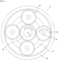
- FIG. 1 represents a cross-sectional view of a speed reducer according to the prior art.
- This figure illustrates an architecture in which the speed reducer 1 comprises a central planetary pinion 2 driven by an input shaft (not shown) movable in rotation about an axis X (perpendicular to the plane of the figure) as well as an external crown 3 coaxial with the planetary pinion 2.
- the reducer 1 further comprises satellite pinions 4 which are meshed with both the planetary pinion 2 and with the external crown 3.
- the satellite pinions 4 are rotatably mounted on pivots 5 of a part called a planet carrier 7 of the reducer 1.
- the teeth of the planetary pinion 2, the crown wheel 3 and the satellite pinions 4 are lubricated by cold lubricating oil which is conveyed through oil distribution channels (not shown) from an oil reservoir (not shown).
- turbojets with high bypass ratios requires a particularly high oil flow rate, to ensure the lubrication and cooling of the pinions and bearings and thus ensure the correct operation of the reducer and the safety of the turbojet.
- EP 3 767 134 A1 describes an oil collector for a mechanical reducer of an aircraft turbomachine.
- WO 2019/141920 A1 describes an oil collector for a speed reducer, in particular for a turbomachine, associated speed reducer and turbomachine.
- the present invention relates to a lubricating oil deflector according to claim 1.
- the configuration of the deflector thus makes it possible, when the latter is arranged in such a way that the first end is at a height situated above the height of the second end, under the effect of the Earth's gravity, to collect lubricating oil present at the first end and to transfer it inside the body, to convey it at a distance from the first end and to evacuate it, at the second distant end, in a direction opposite to the first end.
- the oil present at the first end is recovered at least in part by the latter and transferred to the second end where it is evacuated, which makes it possible to limit the re-circulation of oil around the sun gear and therefore to reduce ventilation losses.
- the present invention relates to a speed reducer of a turbomachine, characterized in that it comprises at least one lubricating oil deflector as briefly explained above.
- This speed reducer has the same features and benefits as the aforementioned deflector.
- the present invention relates to a turbomachine comprising a turbomachine speed reducer as briefly set out above.
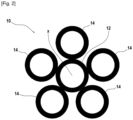
- a speed reducer with planetary architecture of a turbomachine such as an aircraft turbojet with a high bypass ratio fan
- a central sun gear 12 driven by an input shaft (not shown) movable in rotation about an axis X (perpendicular to the vertical plane of the figure) and satellite gears 14 which are arranged in a vertical arrangement (along the axis z) around the sun gear 12.
- the satellite gears 14 are engaged, that is to say meshed, with the sun gear 12.
- the satellite pinions 14 are also also engaged, i.e. meshed, with an external crown (not shown but similar to the crown 3 of the figure 1 ) coaxial with the sun pinion 2. These satellite pinions 14 are rotatably mounted on pivots of a planet carrier part not shown of the reducer 10.
- the figure 1 illustrates a possible configuration for the speed reducer 10, except the number of planet gears which is likely to vary.
- the planetary gearbox can be configured as one stage or two stages.
- the planetary architecture has, for example, a reduction ratio of approximately 2 to 6.
- the teeth of the sun pinion 12, the outer ring gear and the satellite pinions 14 are lubricated by cold lubricating oil which is supplied through oil distribution channels (not shown) from an oil reservoir (not shown).
- the reducer 10 comprises a lubricating oil deflector 20 (fixed to the planet carrier) which extends vertically along the Z axis in a vertical inter-pinion space located between the central sun pinion 12 and the two adjacent planet pinions 14a, 14b located below the sun pinion 12.
- the two adjacent planet pinions 14a, 14b are rotatably mounted on pivots of respective axes Pa, Pb of the planet carrier part not shown and these axes form with the axis X of rotation of the central pinion 12 a triangle (illustrated in dotted lines in FIG. 3) whose tip is oriented upwards and whose base connecting the axes Pa and Pb is horizontal.
- the gravity deflector 20 is thus positioned in the lower part of the reducer 10 so as to promote gravity flow.
- the gravity deflector 20 generally comprises a body 22 having first and second opposite ends 24 and 26. Depending on the location of the gravity deflector 20 in the vertical inter-pinion space defined above, the first end 24 of the gravity deflector is oriented opposite the sun pinion 12 and is located at a vertical position (along the Z axis) greater than that of the second opposite end 26 of the deflector which is located at a distance from the sun pinion (along the Z axis), between the two corresponding adjacent satellite pinions 14a, 14b which frame it.
- THE figures 4 And 5 represent the deflector 20 without the reducer which can integrate it.
- the first end 24, oriented upwards, is configured to receive lubricating oil and here has the shape of a bowl 24a for receiving lubricating oil which collects in particular the oil present in the zone situated between the sun gear 12 and the first end 24.
- the body 22 comprises at least one internal channel (or conduit) 28 for guiding or conveying the oil collected by the bowl 24a and which extends, in a longitudinal direction of extension (here the direction coincides with the vertical), from the first end 24, in particular of the bowl 24a, to the second opposite end 26.
- the oil collected by the bowl 24a flows vertically in the internal channel 28 under the action of gravity and reaches the second opposite end 26 through which the oil is discharged/ejected from the body by gravity.
- only one internal channel 28 is present in the body.
- several channels internal to the body can be envisaged to increase the flow rate of oil to be evacuated, for example by being arranged parallel to each other in the background on the figure 4 (eg: double channel).
- the internal channel 28 can adopt different shapes (in particular its passage section) and dimensions depending on the applications envisaged.
- the internal channel can thus have a rectangular passage section as illustrated in the figure 5 , an oblong, circular passage section...
- FIG 5 shows in perspective a possible example of a shape of a bowl 24a for receiving lubricating oil where the bowl has downwardly oriented curved (concave) walls, substantially forming a V, which partly open out onto an elongated slot 24b (for example of substantially rectangular shape) forming an inlet opening for the internal channel 28.
- the body 22 has a generally elongated shape which extends from the first end 24 to the second end 26 and which is curved in a portion arranged between the first end and the second end and at a distance from them.
- the curved portion is here the central portion 22a of the body according to the cross-sectional view of the Figures 3 and 4 .
- the two opposite ends 24 and 26 each have a general shape that is flared away from the central part 22a of the body.
- the general diabolo shape of the body is thus adapted to the general shape of the vertical inter-pinion space defined above and illustrated in the figure figure 3 .
- the second end 26 of the body takes the form of a substantially flat face 26a which is arranged horizontally when the deflector 20 is in the position of the figure 3 .
- An outlet opening 26b of the internal channel 28a opens at the flat end face 26a to evacuate the oil which flows by gravity into the channel.
- the body has a thickness (dimension perpendicular to the plane of the figure 4 ) which is here constant and a generally rectangular shape according to a view taken in the direction of the lateral arrow indicated in this figure.
- the internal channel 28 here extends along a large part of the thickness of the body.
- the lubricating oil receiving bowl 24a is positioned at the first end of the body in an offset manner in a transverse direction relative to the longitudinal direction of extension of the internal channel 28. Given the vertical orientation of the longitudinal direction of extension, the bowl 24a is thus offset laterally, i.e. horizontally towards one of the two opposite lateral sides of the first end 24.
- the internal channel 28 is also also offset laterally towards the corresponding side of the body. This laterally offset arrangement of the bowl 24a can make it possible, for example, to promote the recovery of oil coming from an area which is located between the sun gear 12 and the satellite gear 14b and towards which the bowl is offset laterally.
- the first end 24 of the body is provided, in a transversely offset manner relative to the longitudinal direction of extension of the channel, with lubricating oil outlet orifices 02 (lubrication nozzles for the solar-satellite gears).
- lubricating oil outlet orifices 02 lubrication nozzles for the solar-satellite gears.
- two outlet ports 02 are shown, aligned along the thickness of the body 22 but a different number can alternatively be envisaged (a transverse conduit not shown allows oil to be conveyed from the bowl 24a to the ejection points 02).
- These ports facilitate the external lubrication of the planet gears and can also contribute to the lubrication of the bearings (outlets for the lubrication of the teeth).
- the gravity deflector 20 has mainly two functions: it guides the lubricating oil between the deflector and each of the satellite gears 14a, 14b and it guides the oil through an internal channel by gravity from the first end 24 to the second end 26.
- the gravity deflector 20 aims to capture/accumulate, in the bowl 24a forming a retention pocket, a portion of the oil present in the circumferential groove (not shown) of the sun gear 12.
- the collected oil accumulates in this bowl where it is slowed down before flowing through the opening 24b through the internal channel 28 under the effect of gravity, thus accelerating the flow of oil.
- the internal channel 28 opens at a distance from the sun gear and the oil is thus evacuated by gravity, exiting through the opening 26b, towards the external ring surrounding the arrangement of the figure 2 , like crown 3 of the figure 1 .
- the gravity deflector 20 plays the role of a gravity-effect accumulator which ensures the internal transfer of a portion of the oil present in the circumferential groove of the sun gear 12 to evacuate it out of this zone and towards the external crown.
- the gravity deflector 20 can be manufactured in different ways, for example by cutting into the mass of a block, by additive manufacturing, by casting or other.
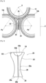
- Figures 6A And 6B illustrate two possible configurations of deflectors 20a and 20b according to which, respectively, the bowl 24a' has, in section, a generally conical shape and the bowl 24a" has, in section, a generally rectangular shape.
- the other characteristics of the deflector may be identical to the deflector 20 described above.
- FIG 7 illustrates another exemplary embodiment of a speed reducer 10' in which one or more gravity deflectors 20', 20", 20'" can be implanted in an inter-pinion space. Only two adjacent satellite pinions 14' of the lower part of the reducer and the sun pinion 12' are shown in solid lines (two other satellite pinions adjacent to the first two are partially schematically shown in dotted lines) but the configuration is generally the same as that of the figure 2 .
- a gravity deflector 20", 20'" can be positioned between the sun pinion 12' and two adjacent satellite pinions 14' in such a way that the first end of the gravity deflector is oriented opposite the sun pinion 12' and is located at a vertical position higher than that of the second opposite end of the deflector concerned.
- the second opposite end of the deflector concerned is located at a distance from the sun pinion 12', between the two corresponding satellite pinions 14'.
- a gravity deflector 20", 20'" thus extends obliquely, relative to the vertical Z, between the sun pinion 12' and the two adjacent satellite pinions 14' in solid lines.
- the angle of inclination between the gravity deflector concerned and the vertical passing through the gravity deflector 20' depends in particular on the number of satellite pinions 14'. The higher this number, the lower the angle of inclination.
- the configuration of the 20", 20'" side gravity deflectors is generally different from that of the 20' gravity deflector although the general external shape may be identical.
- the slope of the internal oil flow guide channel 28" and 28'" for the 20" and 20'" deflectors discharge slope
- this channel 28 is aligned with the general longitudinal direction of the deflector 20), in order to promote the flow of oil towards the bottom of the reducer.
- each internal guide channel 28" and 28'" is inclined downwards relative to the general longitudinal direction of the deflector considered, schematized by the dotted line D1, D2 on the figure 7 .
- the receiving bowl (not shown here) can also be modified from that of the figure 4 , for example, as on the Figures 6A And 6B or in some other way.
- the reducer 10' may also include the deflector 20' identical to the deflector 20 of the Figures 2 to 5 .
- the reducer 10' can include the deflector 20' identical to the deflector 20 of the Figures 2 to 5 and one of the 20", 20'" baffles or all three of the 20', 20" and 20'" baffles.
- the 10' reducer may include only one or the other of the 20", 20"' baffles, without the 20' baffle.
- the turbomachine 30 which is here an aircraft turbojet with a fan, conventionally comprises a fan S, a low-pressure compressor 30a, a high-pressure compressor 30b, an annular combustion chamber 30c, a high-pressure turbine 30d, a low-pressure turbine 30e and an exhaust nozzle 30f.
- the high-pressure compressor 30b and the high-pressure turbine 30d are connected by a high-pressure shaft 32 and form with it a high-pressure (HP) body.
- the low-pressure compressor 30a and the low-pressure turbine 30e are connected by a low-pressure shaft 33 and form with it a low-pressure (LP) body.
- the fan S is driven by a fan shaft 34 which is driven by the LP shaft 33 by means of a speed reducer 36.
- This reducer is here of the planetary type and is positioned in the front part of the turbomachine.
- a fixed structure schematically comprising, here, an upstream part 35a and a downstream part 35b which composes the engine casing or stator 35 is arranged so as to form an enclosure E surrounding the reducer 36.
- This enclosure E is here closed upstream by seals at a bearing allowing the crossing of the fan shaft 34 and downstream by seals at the crossing of the BP shaft 33.
- turbomachine configurations are of course conceivable for implementing the invention.
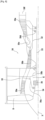
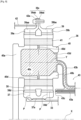
- FIG 9 illustrates a possible example of configuration (following an axial half-section) for the reducer 36 of the figure 8 .
- the reducer 36 is connected to the BP shaft 33, for example via splines 37a.
- the BP shaft 33 drives a sun gear 37.
- the sun gear 37 whose axis of rotation coincides with that of the turbomachine X, drives a series of satellite gears 38, which are equally distributed on the same diameter around the axis of rotation X. This diameter is equal to twice the operating center distance between sun gears 37 and satellite gears 38.
- the number of satellite gears 38 is generally defined between three and seven for this type of application.
- the set of satellite pinions 38 is held, at the output, by a frame called a planet carrier 40.
- Each satellite 38 rotates around its own Y axis, and meshes with the external crown 39.
- the planet carrier 40 is fixed to the motor housing or stator 35 of the figure 8 .
- Each satellite 38 drives the crown 39 which is attached to the fan shaft 34 ( fig. 8 ) via a 42 crown holder.
- Each satellite 38 is mounted to rotate freely using a bearing 41, for example of the rolling bearing or hydrostatic bearing type.
- Each bearing 41 is mounted on one of the axes 40b of the planet carrier 40 and all the axes are positioned relative to each other using one or more structural frames 40a of the planet carrier 40.
- the teeth of a reducer can, for example, be separated into several helices.
- the operation of a reducer with several propellers with a crown separated into two half-crowns will be described below.
- a front half-crown 39a consists of a rim 39aa and a half-fixing flange 39ab. On the rim 39aa is the front helix of the gear teeth. This front helix meshes with that of the satellite 38 which meshes with that of the solar 37.
- a rear half-crown 39b consisting of a rim 39ba and a half-fixing flange 39bb.
- On the rim 39ba is the rear helix of the gear teeth. This rear helix meshes with that of the satellite 38 which meshes with that of the solar 37.
- the half-clamp 39ab of the front crown 39a and the half-clamp 39bb of the rear crown 39b form the crown mounting flange 39c.
- the crown 39 is fixed to a crown carrier by assembling the crown mounting flange 39c and the crown carrier mounting flange 42a using a bolted assembly for example.
- the arrows of the figure 9 describe the routing of the oil in the reducer 36.
- the oil arrives in the reducer 36 from the stator part 35 ( fig. 8 ) in the distributor 43 by different means which will not be specified in this view because they are specific to one or more types of architecture.
- the distributor is divided into two parts in general, each repeated by the same number of satellites.
- the injectors 43a have the function of lubricating the teeth and the arms 43b have the function of lubricating the bearings.
- the oil is brought to the injector 43a to exit through the end 43c in order to lubricate the teeth.
- the oil is also brought to the arm 43b and circulates via the supply mouth 43d of the bearing.
- the oil then circulates through the axis in one or more buffer zones 40c to then exit through the orifices 40d in order to lubricate the bearings of the satellites.
Landscapes
- Engineering & Computer Science (AREA)
- General Engineering & Computer Science (AREA)
- Mechanical Engineering (AREA)
- General Details Of Gearings (AREA)
Claims (12)
- Schmieröldeflektor (20; 20', 20", 20"') für ein Untersetzungsgetriebe einer Turbomaschine, wobei der Deflektor einen Körper (22) mit einem ersten Ende (24), das dazu gedacht ist, gegenüber einem Sonnenrad des Untersetzungsgetriebes angeordnet zu sein, und einem gegenüberliegenden zweiten Ende (26) umfasst, wobei der Körper (22) zwei Seitenflächen beinhaltet, die jeweils dazu gedacht sind, gegenüber einem Planetenrad des Getriebes angeordnet zu sein und die jeweils das erste und das zweite Ende (24, 26) miteinander verbinden, wobei der Körper (22) mindestens einen inneren Ölführungskanal (28) beinhaltet, dadurch gekennzeichnet, dass das erste Ende (24) des Körpers (22) dazu ausgestaltet ist, das Öl des Sonnenrads aufzunehmen und das gegenüberliegende zweite Ende (26) dazu ausgestaltet ist, das Öl aus dem Körper (22) abzuleiten, wobei der innere Ölführungskanal (28) in dem ersten Ende (24) und in dem zweiten Ende (26) mündet und dazu ausgestaltet ist, das Öl durch Schwerkraft durch das zweite Ende (26) abzuleiten.
- Schmieröldeflektor nach Anspruch 1, dadurch gekennzeichnet, dass das erste Ende (24) eine Schmierölaufnahmeschale (24a) beinhaltet, die dazu gedacht ist, Öl aufzunehmen.
- Schmieröldeflektor nach Anspruch 2, dadurch gekennzeichnet, dass sich der mindestens eine innere Führungskanal (28) entlang einer Längserstreckungsrichtung erstreckt, wobei die Schmierölaufnahmeschale (24a) an dem ersten Ende (24) des Körpers auf versetzte Weise entlang einer Querrichtung relativ zu der Längserstreckungsrichtung positioniert ist.
- Schmieröldeflektor nach Anspruch 2 oder 3, dadurch gekennzeichnet, dass sich der mindestens eine innere Führungskanal (28) entlang einer Längserstreckungsrichtung erstreckt, wobei das erste Ende (24) des Körpers auf versetzte Weise entlang einer Querrichtung relativ zu der Längserstreckungsrichtung, von Schmierölauslassöffnungen (02), vorgesehen ist.
- Schmieröldeflektor nach einem der vorhergehenden Ansprüche, dadurch gekennzeichnet, dass der Körper (22) eine im Allgemeinen längliche Form aufweist, die sich von dem ersten Ende (24) zu dem zweiten Ende (26) erstreckt.
- Schmieröldeflektor nach dem vorhergehenden Anspruch, dadurch gekennzeichnet, dass die im Allgemeinen längliche Form des Körpers in einem Teil (22a) gekrümmt ist, der zwischen dem ersten Ende (24) und dem zweiten Ende (26) und in einem Abstand davon angeordnet ist.
- Untersetzungsgetriebe (10; 10') einer Turbomaschine, dadurch gekennzeichnet, dass es mindestens einen Schmieröldeflektor (20; 20', 20", 20‴) nach einem der Ansprüche 1 bis 6 umfasst.
- Untersetzungsgetriebe (10; 10') einer Turbomaschine nach dem vorhergehenden Anspruch, dadurch gekennzeichnet, dass es ein Sonnenrad (12) und Planetenräder (14), die um das Sonnenrad angeordnet sind und die einerseits mit dem Sonnenrad und andererseits mit einem Hohlrad, das sich um die Planetenräder erstreckt, im Eingriff sind, umfasst.
- Untersetzungsgetriebe (10) einer Turbomaschine nach dem vorhergehenden Anspruch, dadurch gekennzeichnet, dass die Planetenräder (14) entlang einer vertikalen Anordnung um das Sonnenrad (12) bereitgestellt sind, sich ein oder mehrere Schmieröldeflektoren (20; 20', 20", 20‴) nach einem der Ansprüche 1 bis 6 jeweils zwischen dem Sonnenrad (12; 12') und zwei benachbarten Planetenrädern (14; 14') auf eine solche Weise erstrecken, dass das erste Ende (24) des Deflektors oder der Deflektoren gegenüber dem Sonnenrad (12; 12') ausgerichtet ist und sich in einer vertikalen Position befindet, die höher als diejenige des zweiten gegenüberliegenden Endes (26) des betreffenden Deflektors ist, das sich in einem Abstand von dem Sonnenrad zwischen den zwei entsprechenden umlaufend benachbarten Planetenrädern (14; 14') befindet.
- Untersetzungsgetriebe (10) einer Turbomaschine nach dem vorhergehenden Anspruch, dadurch gekennzeichnet, dass es einen Schmieröldeflektor (20) beinhaltet, der sich vertikal zwischen dem Sonnenrad (12) und zwei umlaufend benachbarten Planetenrädern (14, 14a, 14b) erstreckt.
- Untersetzungsgetriebe (10') einer Turbomaschine nach einem der Ansprüche 8 bis 10, dadurch gekennzeichnet, dass es mindestens einen Schmieröldeflektor (20", 20‴) beinhaltet, der sich auf schräge Weise zwischen dem Sonnenrad (12') und zwei benachbarten Planetenrädern (14') erstreckt.
- Turbomaschine, dadurch gekennzeichnet, dass sie ein Untersetzungsgetriebe (10; 10') einer Turbomaschine nach einem der Ansprüche 7 bis 11 umfasst.
Applications Claiming Priority (1)
| Application Number | Priority Date | Filing Date | Title |
|---|---|---|---|
| FR2202313A FR3133654B1 (fr) | 2022-03-16 | 2022-03-16 | Déflecteur d’huile de lubrification, réducteur de vitesse comportant un tel déflecteur et turbomachine comportant un tel réducteur de vitesse. |
Publications (2)
| Publication Number | Publication Date |
|---|---|
| EP4246018A1 EP4246018A1 (de) | 2023-09-20 |
| EP4246018B1 true EP4246018B1 (de) | 2024-12-18 |
Family
ID=81749106
Family Applications (1)
| Application Number | Title | Priority Date | Filing Date |
|---|---|---|---|
| EP23160827.4A Active EP4246018B1 (de) | 2022-03-16 | 2023-03-08 | Schmieröldeflektor, untersetzungsgetriebe mit solch einem deflektor und turbomaschine mit solch einem geschwindigkeitsminderer |
Country Status (3)
| Country | Link |
|---|---|
| US (1) | US12140220B2 (de) |
| EP (1) | EP4246018B1 (de) |
| FR (1) | FR3133654B1 (de) |
Families Citing this family (2)
| Publication number | Priority date | Publication date | Assignee | Title |
|---|---|---|---|---|
| CN118088630B (zh) * | 2024-04-26 | 2024-06-25 | 常州市曼多林精密机械科技股份有限公司 | 一种行星架自适型紧固的行星齿轮减速机 |
| US12540667B2 (en) | 2024-06-04 | 2026-02-03 | Pratt & Whitney Canada Corp. | Combined rotating component and fluid port baffle |
Family Cites Families (8)
| Publication number | Priority date | Publication date | Assignee | Title |
|---|---|---|---|---|
| US9476321B2 (en) * | 2012-09-20 | 2016-10-25 | United Technologies Corporation | Turbomachine fluid delivery manifold and system |
| US9038779B2 (en) * | 2013-08-30 | 2015-05-26 | United Technologies Corporation | Geared architecture gas turbine engine with oil scavenge |
| US10202902B2 (en) * | 2013-08-30 | 2019-02-12 | United Technologies Corporation | Geared architecture gas turbine engine with oil scavenge |
| FR3076853B1 (fr) * | 2018-01-16 | 2021-03-19 | Safran Trans Systems | Collecteur d'huile pour reducteur de vitesse notamment de turbomachine, reducteur de vitesse et turbomachine associes |
| GB201809373D0 (en) * | 2018-06-07 | 2018-07-25 | Rolls Royce Plc | A gearbox and a geared gas turbine engine |
| GB201819768D0 (en) * | 2018-12-04 | 2019-01-23 | Rolls Royce Plc | A method of manufacturing a planet carrier of a gearbox |
| FR3098877B1 (fr) * | 2019-07-16 | 2023-03-17 | Safran Trans Systems | Collecteur d’huile pour un reducteur mecanique de turbomachine d’aeronef |
| FR3103529B1 (fr) * | 2019-11-22 | 2021-11-19 | Safran Trans Systems | Alimentation et recuperation d’huile de lubrification dans un reducteur mecanique de turbomachine d’aeronef |
-
2022
- 2022-03-16 FR FR2202313A patent/FR3133654B1/fr active Active
-
2023
- 2023-03-08 EP EP23160827.4A patent/EP4246018B1/de active Active
- 2023-03-14 US US18/183,688 patent/US12140220B2/en active Active
Also Published As
| Publication number | Publication date |
|---|---|
| EP4246018A1 (de) | 2023-09-20 |
| FR3133654B1 (fr) | 2024-03-15 |
| FR3133654A1 (fr) | 2023-09-22 |
| US12140220B2 (en) | 2024-11-12 |
| US20230296168A1 (en) | 2023-09-21 |
Similar Documents
| Publication | Publication Date | Title |
|---|---|---|
| EP3408504B1 (de) | Sich drehender ölverteiler mit axialer partitionierung und planeten-untersetzungsgetriebe mit einem solchen ölverteiler | |
| EP3575562B1 (de) | Leistungsübertragungssystem, das eine schmierölrückgewinnungsvorrichtung umfasst, und mit einem solchen leistungsübertragungssystem ausgestattetes turbotriebwerk | |
| CA2864975C (fr) | Dispositif de recuperation de l'huile de lubrification d'un reducteur epicycloidal | |
| CA2940978C (fr) | Rotor de soufflante pour une turbomachine telle qu'un turboreacteur multiflux entraine par reducteur | |
| EP3283747B1 (de) | Turbomaschine mit einem dem gasgenerator vorgeschalteten paar von gegenläufigen propellern | |
| EP3599397B1 (de) | Vorrichtung vom typ untersetzungs- oder differenzialgetriebe für ein turbotriebwerk eines luftfahrzeugs | |
| EP4246018B1 (de) | Schmieröldeflektor, untersetzungsgetriebe mit solch einem deflektor und turbomaschine mit solch einem geschwindigkeitsminderer | |
| FR3043714A1 (fr) | Partie avant de turbomachine d'aeronef comprenant une soufflante unique entrainee par un reducteur, ainsi que des aubes directrices de sortie structurales agencees en partie en amont d'un bec de separation | |
| EP3956555B1 (de) | Reduktionsgetriebe einer turbomaschine | |
| FR2987402A1 (fr) | Dispositif de lubrification d'un reducteur epicycloidal compatible d'un montage modulaire. | |
| EP4150199A1 (de) | Turbomaschine eines luftfahrzeugs, die eine schmiervorrichtung eines lagers umfasst | |
| FR2987417A1 (fr) | Dispositif de recuperation de l'huile de lubrification d'un reducteur epicycloidal. | |
| EP3705705A1 (de) | Mechanisches reduktionsgetriebe für luftfahrzeug-turbotriebwerk | |
| EP3740657A1 (de) | Ölsammler für ein untersetzungsgetriebe, insbesondere einer turbomaschine sowie zugehöriges untersetzungsgetriebe und turbomaschine | |
| EP4407149B1 (de) | Anordnung für eine strömungsmaschine mit schmiermittelabführungsmitteln und strömungsmaschine mit einer solchen anordnung | |
| FR3080652A1 (fr) | Turbomachine a architecture inversee, optionnellement pourvue d'un recuperateur de chaleur en sortie de turbine basse pression | |
| EP4382775B1 (de) | Schmierölrückgewinnungsrinne für reduktionsgetriebe | |
| EP4001703A1 (de) | Ritzel mit schmiervorrichtung | |
| FR3164767A1 (fr) | Reducteur mecanique a elements planetaires pourvu d’un dispositif de lubrification | |
| FR3164252A1 (fr) | Système de trains épicycloïdaux pour turbomachine et turbomachine comprenant un tel système | |
| FR3153866A1 (fr) | Reducteur mecanique de vitesse a barbotage d’huile | |
| FR3104212A1 (fr) | Turbomachine a turbine contrarotative pour un aeronef |
Legal Events
| Date | Code | Title | Description |
|---|---|---|---|
| PUAI | Public reference made under article 153(3) epc to a published international application that has entered the european phase |
Free format text: ORIGINAL CODE: 0009012 |
|
| STAA | Information on the status of an ep patent application or granted ep patent |
Free format text: STATUS: REQUEST FOR EXAMINATION WAS MADE |
|
| 17P | Request for examination filed |
Effective date: 20230308 |
|
| AK | Designated contracting states |
Kind code of ref document: A1 Designated state(s): AL AT BE BG CH CY CZ DE DK EE ES FI FR GB GR HR HU IE IS IT LI LT LU LV MC ME MK MT NL NO PL PT RO RS SE SI SK SM TR |
|
| GRAP | Despatch of communication of intention to grant a patent |
Free format text: ORIGINAL CODE: EPIDOSNIGR1 |
|
| STAA | Information on the status of an ep patent application or granted ep patent |
Free format text: STATUS: GRANT OF PATENT IS INTENDED |
|
| INTG | Intention to grant announced |
Effective date: 20240731 |
|
| RIN1 | Information on inventor provided before grant (corrected) |
Inventor name: MARCOS IZQUIERDO, JUAN-LUIS |
|
| GRAS | Grant fee paid |
Free format text: ORIGINAL CODE: EPIDOSNIGR3 |
|
| GRAA | (expected) grant |
Free format text: ORIGINAL CODE: 0009210 |
|
| STAA | Information on the status of an ep patent application or granted ep patent |
Free format text: STATUS: THE PATENT HAS BEEN GRANTED |
|
| AK | Designated contracting states |
Kind code of ref document: B1 Designated state(s): AL AT BE BG CH CY CZ DE DK EE ES FI FR GB GR HR HU IE IS IT LI LT LU LV MC ME MK MT NL NO PL PT RO RS SE SI SK SM TR |
|
| REG | Reference to a national code |
Ref country code: CH Ref legal event code: EP |
|
| REG | Reference to a national code |
Ref country code: DE Ref legal event code: R096 Ref document number: 602023001370 Country of ref document: DE |
|
| REG | Reference to a national code |
Ref country code: IE Ref legal event code: FG4D Free format text: LANGUAGE OF EP DOCUMENT: FRENCH |
|
| REG | Reference to a national code |
Ref country code: LT Ref legal event code: MG9D |
|
| PG25 | Lapsed in a contracting state [announced via postgrant information from national office to epo] |
Ref country code: HR Free format text: LAPSE BECAUSE OF FAILURE TO SUBMIT A TRANSLATION OF THE DESCRIPTION OR TO PAY THE FEE WITHIN THE PRESCRIBED TIME-LIMIT Effective date: 20241218 |
|
| PGFP | Annual fee paid to national office [announced via postgrant information from national office to epo] |
Ref country code: DE Payment date: 20250218 Year of fee payment: 3 |
|
| PG25 | Lapsed in a contracting state [announced via postgrant information from national office to epo] |
Ref country code: FI Free format text: LAPSE BECAUSE OF FAILURE TO SUBMIT A TRANSLATION OF THE DESCRIPTION OR TO PAY THE FEE WITHIN THE PRESCRIBED TIME-LIMIT Effective date: 20241218 |
|
| PG25 | Lapsed in a contracting state [announced via postgrant information from national office to epo] |
Ref country code: BG Free format text: LAPSE BECAUSE OF FAILURE TO SUBMIT A TRANSLATION OF THE DESCRIPTION OR TO PAY THE FEE WITHIN THE PRESCRIBED TIME-LIMIT Effective date: 20241218 |
|
| PG25 | Lapsed in a contracting state [announced via postgrant information from national office to epo] |
Ref country code: NO Free format text: LAPSE BECAUSE OF FAILURE TO SUBMIT A TRANSLATION OF THE DESCRIPTION OR TO PAY THE FEE WITHIN THE PRESCRIBED TIME-LIMIT Effective date: 20250318 |
|
| REG | Reference to a national code |
Ref country code: NL Ref legal event code: MP Effective date: 20241218 |
|
| PG25 | Lapsed in a contracting state [announced via postgrant information from national office to epo] |
Ref country code: LV Free format text: LAPSE BECAUSE OF FAILURE TO SUBMIT A TRANSLATION OF THE DESCRIPTION OR TO PAY THE FEE WITHIN THE PRESCRIBED TIME-LIMIT Effective date: 20241218 Ref country code: GR Free format text: LAPSE BECAUSE OF FAILURE TO SUBMIT A TRANSLATION OF THE DESCRIPTION OR TO PAY THE FEE WITHIN THE PRESCRIBED TIME-LIMIT Effective date: 20250319 |
|
| PGFP | Annual fee paid to national office [announced via postgrant information from national office to epo] |
Ref country code: FR Payment date: 20250219 Year of fee payment: 3 |
|
| PG25 | Lapsed in a contracting state [announced via postgrant information from national office to epo] |
Ref country code: RS Free format text: LAPSE BECAUSE OF FAILURE TO SUBMIT A TRANSLATION OF THE DESCRIPTION OR TO PAY THE FEE WITHIN THE PRESCRIBED TIME-LIMIT Effective date: 20250318 |
|
| PG25 | Lapsed in a contracting state [announced via postgrant information from national office to epo] |
Ref country code: NL Free format text: LAPSE BECAUSE OF FAILURE TO SUBMIT A TRANSLATION OF THE DESCRIPTION OR TO PAY THE FEE WITHIN THE PRESCRIBED TIME-LIMIT Effective date: 20241218 |
|
| REG | Reference to a national code |
Ref country code: AT Ref legal event code: MK05 Ref document number: 1752453 Country of ref document: AT Kind code of ref document: T Effective date: 20241218 |
|
| PG25 | Lapsed in a contracting state [announced via postgrant information from national office to epo] |
Ref country code: SM Free format text: LAPSE BECAUSE OF FAILURE TO SUBMIT A TRANSLATION OF THE DESCRIPTION OR TO PAY THE FEE WITHIN THE PRESCRIBED TIME-LIMIT Effective date: 20241218 |
|
| PG25 | Lapsed in a contracting state [announced via postgrant information from national office to epo] |
Ref country code: PL Free format text: LAPSE BECAUSE OF FAILURE TO SUBMIT A TRANSLATION OF THE DESCRIPTION OR TO PAY THE FEE WITHIN THE PRESCRIBED TIME-LIMIT Effective date: 20241218 |
|
| PG25 | Lapsed in a contracting state [announced via postgrant information from national office to epo] |
Ref country code: ES Free format text: LAPSE BECAUSE OF FAILURE TO SUBMIT A TRANSLATION OF THE DESCRIPTION OR TO PAY THE FEE WITHIN THE PRESCRIBED TIME-LIMIT Effective date: 20241218 |
|
| PG25 | Lapsed in a contracting state [announced via postgrant information from national office to epo] |
Ref country code: IS Free format text: LAPSE BECAUSE OF FAILURE TO SUBMIT A TRANSLATION OF THE DESCRIPTION OR TO PAY THE FEE WITHIN THE PRESCRIBED TIME-LIMIT Effective date: 20250418 |
|
| PG25 | Lapsed in a contracting state [announced via postgrant information from national office to epo] |
Ref country code: PT Free format text: LAPSE BECAUSE OF FAILURE TO SUBMIT A TRANSLATION OF THE DESCRIPTION OR TO PAY THE FEE WITHIN THE PRESCRIBED TIME-LIMIT Effective date: 20250421 |
|
| PG25 | Lapsed in a contracting state [announced via postgrant information from national office to epo] |
Ref country code: EE Free format text: LAPSE BECAUSE OF FAILURE TO SUBMIT A TRANSLATION OF THE DESCRIPTION OR TO PAY THE FEE WITHIN THE PRESCRIBED TIME-LIMIT Effective date: 20241218 |
|
| PG25 | Lapsed in a contracting state [announced via postgrant information from national office to epo] |
Ref country code: AT Free format text: LAPSE BECAUSE OF FAILURE TO SUBMIT A TRANSLATION OF THE DESCRIPTION OR TO PAY THE FEE WITHIN THE PRESCRIBED TIME-LIMIT Effective date: 20241218 Ref country code: RO Free format text: LAPSE BECAUSE OF FAILURE TO SUBMIT A TRANSLATION OF THE DESCRIPTION OR TO PAY THE FEE WITHIN THE PRESCRIBED TIME-LIMIT Effective date: 20241218 |
|
| PG25 | Lapsed in a contracting state [announced via postgrant information from national office to epo] |
Ref country code: SK Free format text: LAPSE BECAUSE OF FAILURE TO SUBMIT A TRANSLATION OF THE DESCRIPTION OR TO PAY THE FEE WITHIN THE PRESCRIBED TIME-LIMIT Effective date: 20241218 |
|
| PG25 | Lapsed in a contracting state [announced via postgrant information from national office to epo] |
Ref country code: CZ Free format text: LAPSE BECAUSE OF FAILURE TO SUBMIT A TRANSLATION OF THE DESCRIPTION OR TO PAY THE FEE WITHIN THE PRESCRIBED TIME-LIMIT Effective date: 20241218 |
|
| PG25 | Lapsed in a contracting state [announced via postgrant information from national office to epo] |
Ref country code: IT Free format text: LAPSE BECAUSE OF FAILURE TO SUBMIT A TRANSLATION OF THE DESCRIPTION OR TO PAY THE FEE WITHIN THE PRESCRIBED TIME-LIMIT Effective date: 20241218 |
|
| PG25 | Lapsed in a contracting state [announced via postgrant information from national office to epo] |
Ref country code: SE Free format text: LAPSE BECAUSE OF FAILURE TO SUBMIT A TRANSLATION OF THE DESCRIPTION OR TO PAY THE FEE WITHIN THE PRESCRIBED TIME-LIMIT Effective date: 20241218 |
|
| REG | Reference to a national code |
Ref country code: DE Ref legal event code: R097 Ref document number: 602023001370 Country of ref document: DE |
|
| PG25 | Lapsed in a contracting state [announced via postgrant information from national office to epo] |
Ref country code: DK Free format text: LAPSE BECAUSE OF FAILURE TO SUBMIT A TRANSLATION OF THE DESCRIPTION OR TO PAY THE FEE WITHIN THE PRESCRIBED TIME-LIMIT Effective date: 20241218 |
|
| PG25 | Lapsed in a contracting state [announced via postgrant information from national office to epo] |
Ref country code: MC Free format text: LAPSE BECAUSE OF FAILURE TO SUBMIT A TRANSLATION OF THE DESCRIPTION OR TO PAY THE FEE WITHIN THE PRESCRIBED TIME-LIMIT Effective date: 20241218 |
|
| PLBE | No opposition filed within time limit |
Free format text: ORIGINAL CODE: 0009261 |
|
| STAA | Information on the status of an ep patent application or granted ep patent |
Free format text: STATUS: NO OPPOSITION FILED WITHIN TIME LIMIT |
|
| PG25 | Lapsed in a contracting state [announced via postgrant information from national office to epo] |
Ref country code: LU Free format text: LAPSE BECAUSE OF NON-PAYMENT OF DUE FEES Effective date: 20250308 |
|
| 26N | No opposition filed |
Effective date: 20250919 |
|
| REG | Reference to a national code |
Ref country code: BE Ref legal event code: MM Effective date: 20250331 |
|
| PG25 | Lapsed in a contracting state [announced via postgrant information from national office to epo] |
Ref country code: BE Free format text: LAPSE BECAUSE OF NON-PAYMENT OF DUE FEES Effective date: 20250331 |
|
| PG25 | Lapsed in a contracting state [announced via postgrant information from national office to epo] |
Ref country code: IE Free format text: LAPSE BECAUSE OF NON-PAYMENT OF DUE FEES Effective date: 20250308 |